Design and development of a decline shaft through poorly consolidated Kalahari deposits at Ghaghoo Diamond Mine.
|
|
|
- Lambert Hampton
- 6 years ago
- Views:
Transcription
1 Design and development of a decline shaft through poorly consolidated Kalahari deposits at Ghaghoo Diamond Mine. Alan Naismith 1, Dr Graham Howell 2, Howard Marsden 3. 1 SRK; 2 SRK; 3 Petra Diamonds (previously, GEM Diamonds). SYNOPSIS The diamond pipe at Ghaghoo is overlain by approximately 70m of poorly consolidated Kalahari sequence deposits consisting of fine grained aeolian sand particles which are cemented weakly by a clay (smectite) binder. In places the sequence is more strongly cemented with calcite (calcrete) or silica (silcrete). The thickness and geotechnical characteristics of this sequence presented a challenge with regard to accessing the pipe. An innovative decline shaft construction method using and Open Face Tunnelling Shield (OFTS) with installation of a segmental concrete lining for long term support was selected. While this method has been used extensively in international tunnelling projects, development usually has been close to horizontal. Little experience existed of development on an 8 (1 in 7.1) gradient. Development of the box cut commenced during July An artificial portal was created, approximately 25m below surface, to minimise the cost and risk associated with box cut development. Construction of the 6m diameter OFTS on site commenced in November 2011 and excavation of the decline commenced in December A total of 758, 600mm wide concrete rings were installed in the Kalahari deposits and weathered basalt before conventional development continued in basalt. This paper briefly presents aspects of the design philosophy and method, construction and monitoring processes involved in excavating the box cut, constructing the portal and sinking the decline shaft. 1. INTRODUCTION The ore body at Ghaghoo is covered by weakly cemented Kalahari deposits approximately 70m in thickness. Access to the ore body is via a decline shaft constructed at a gradient of 1 in 7.1 (8 ) over a linear distance of approximately 500m through the Kalahari sediments and a further 70m through weathered basalt before reaching competent basalt. The decline will continue to service successive mining phases over a potential mine life exceeding 40 years. A minimum cross sectional area of 20m² is required for ventilation of the early phases of mine development. Due to the remote location of the mine and the difficulty in travelling over a distance of 180km on sand roads, key parameters to be considered in the access design included:-
2 minimisation of initial capital expenditure; minimisation of mass of material and equipment to be transported to site; Maximum loads per vehicle were restricted to 10t. maximum use of on-site material; i.e. use of sand and waste rock for construction. minimisation of access risk to maintain safety and the planned development schedule; minimisation of development time. This paper describes the geotechnical design and construction of the access development and includes: - box cut to provide access to the portal; the access portal; decline developed in Kalahari sequence sediments; decline developed through the transition zone; 2. THE KALAHARI SEQUENCE AT GHAGHOO This sequence contains three geotechnical sub-domains:- Upper domain consisting of loose, unconsolidated aeolian sand. This domain was approximately 10m thick; Mid-domain consisting of weakly cemented fine grained aeolian sand with discrete lenses of silt and clay, gravel silcrete and calcrete. The silcrete/calcrete portion proved to form a significant, 20m thick portion of this domain in which the uniaxial strength of the silcrete was found to exceed 100MPa. The vertical thickness of this domain was approximately 55m; Lower domain consisting of oxidized and friable fine grained aeolian sand which was expected to be moist to wet. Although the cementing properties of the sand had been largely destroyed by water action, the material was relatively dry when encountered and was not prone to slumping as expected. The vertical thickness of this domain was a maximum of 5m. A selection of site investigation boreholes is presented in Figure 1 to illustrate the variation in conditions across the site. A typical core sample is shown in Figure 2. Much of the sand sequence could not be recovered with conventional coring and a wash system was used to collect samples which were stored in plastic sleeves in core boxes. Samples of sand from GEM08-01 were selected for laboratory testing. The average strength of sand, recorded from four tests, is 500kPa with a range from 300kPa to 680kPa. The strength of calcrete/silcrete that has been encountered in the sequence varies widely with a lower bound of 22MPa and an upper bound of 133MPa being recorded in three tests. Based on the particle size distribution, sand was classified using the Unified Soil Classification System (USCS) and generally expected properties can be derived. The basic
3 classification is illustrated in Table I. The average value of friction angle determined for Ghaghoo using this system is 34. USCS Class SW SP SM SC Description Well graded sand. Little or no fines Poorly graded sand. Little or no fines Silty sands. Small percentage of fines Clayey sand. Small percentage of fines Angle of Friction (φ ) Range (+/-) No of samples in class Table I: The Unified Soil Classification System applied to Kalahari sand.

4 Figure 1: Lithology encountered in site investigation boreholes within the decline space.


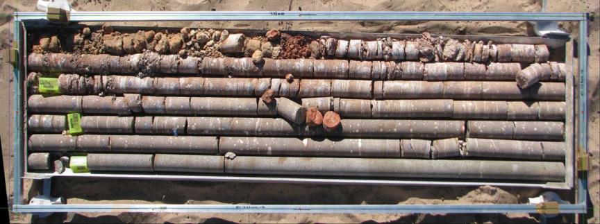
5 Figure 2: Borehole GT08-01 showing the Kalahari sequence, transitional and competent basalt
6 3. RAINFALL Based on monthly rainfall figures over the period 1959 to 1987, the annual rainfall is, on average, slightly more than 400mm. The highest rainfall is experienced from November to February with rain also in October, March and April. Occasional storm rainfall events can exceed 70mm within a 24 hour period. In summary, there is a probability of 9.4% that rainfall exceeding 100mm will fall in any month. The probability is 23% that falls exceeding 100mm will occur between November and February. There is a probability of 94.4% that rainfall during the period June to October will be less than 50mm in any month. This information was used in determining surface water handling facilities that need to be incorporated into the design and to determine risk to construction due to flooding. 4. DECLINE SYSTEM DESIGN The decline system at Ghaghoo was defined in terms of four critical risk areas. These were: - box cut to provide access to the portal; the access portal; decline developed in Kalahari sequence sediments; decline developed through the transition zone; Anticipated risks and mitigation measures are summarised in Table II: - Project design area Anticipated major risks Mitigation measures Box cut access to the portal The access portal The decline developed in Kalahari sequence sands. Collapse of sidewalls overrunning the access portal Flooding of excavations due to storm rainfall. Collapse of portal slope. Collapse of face during launching of the shield Collapse of the face during excavation. Collapse of developed sections of the tunnel. Slopes are designed at a conservative angle to ensure life-of-mine stability (safety factor > 1.5). A bund is constructed around the box cut to restrict inflow. Sump and pumping capacity provide water handling infrastructure. Additional surface support is provided. Ground reinforcement and consolidation is applied. Standard Operational Procedure implemented. Support is offered by the shield. Standard Operational Procedure implemented. Lining designed to sustain loads
7 The decline developed through the transition zone. Flooding due to groundwater influx. Face collapse in weak material. equivalent to at least 80m of cover. Cover drilling to identify ground water accumulations. Ground consolidation where necessary. Table II: Anticipated risks and their mitigation measures. 5. BOX CUT DESIGN A base case design, which assumed that the box cut was excavated to a depth sufficient to create a portal in competent basalt (approximately 80m), provided, initial figures for comparison with alternative options. A number of different options were analysed. These were: Base case: 30 slope with maximum depth 80m; Option 2: 28 slope with maximum depth 80m; Option 3: 30 slope with maximum depth 20m; Option 4: 30 slope with maximum depth 25m Option 5: 30 slope with maximum depth 30m; Option 6: 30 slope with maximum depth 35m; Option 7: 60 slope reinforced with soil nails and cladding with maximum depth 25m; Option 8: 12m vertical, stepped faces supported by contiguous piles with maximum depth 25m. The excavation volumes and representative surface areas for each option were calculated and a trade-off study based on technical and economic criteria carried out. Although Option 3 appeared to be preferable, to reduce the risk associated with creating a portal at very shallow depth in material consisting primarily of aeolian sand, it was decided to implement Option 4 with the further modification that the slope angle was reduced to 25. The design assumptions for this option to satisfy the requirements of the preliminary mining phase then became:- Stable slope angle is 25 ; Although no support of sidewalls was envisaged to enhance stability, during construction it was decided to apply shotcrete to the lower portions of the slopes to prevent erosion and choking of the drains and sump with sand; Rain fall onto the catchment footprint can be controlled by drainage into a sump and bund walls to prevent ingress from an extensive outlying area; Ramp angle is 8 ; The ramp width is 12m;
8 Depth to the tunnel invert at the portal is 25m. The general configuration of the box cut is shown in Figure 3 and a panorama showing graded slopes in Figure 4: -
9 Figure 3: General configuration of the 25m Box Cut.

10 Figure 4: Panorama of the completed box cut showing graded slopes, December PORTAL DESIGN The purpose of the portal construction is to provide a secure face into which the decline can be developed. The design for portal construction included:- additional support of ramp sidewalls within 25m of the portal face with a nominal 50mm thickness of shotcrete; entry; additional excavation of the portal face to create a sub-vertical face for the decline additional support of the portal face using fully grouted soil nails in conjunction with 300mm of mesh reinforced shotcrete; support of the area peripheral to the decline access using 25mm diameter, 12m long spiling bars. Additional excavation required to establish the portal face was carried out in lifts approximately 1.5m in height to facilitate installation of soil nail support and concurrent shotcrete application. The general layout of the portal face together with recommended support is presented in Figure 5 while Figure 6 shows construction in progress.

11 Figure 5: General support layout for the portal (front elevation). Figure 6: Portal construction showing mesh installation prior to shotcrete placement.
12 7. DECLINE SHAFT DESIGN A number of methods that have been used internationally to create tunnels in weak, poorly consolidated, ground were reviewed and a high level risk assessment was carried out on each of these methods with regard to their application to the decline at Ghaghoo. Key evaluation factors considered are safety, cost and schedule. The results of the evaluation are presented in Table III. Using the scoring system to evaluate key parameters, the Open Face Shield (OFS) system was found to be preferable (manual shield). In this system, a narrow protective shield is advanced incrementally using hydraulic rams. The shield provides lateral support to surrounding ground while the face is exposed and advanced continuously. Excavation at the face uses mechanical or manual methods with waste material removed by conveyor. Once a certain amount of material has been excavated from the face, the shield is jacked forward using arrays of hydraulic rams acting against installed concrete segments to guide and maintain alignment. There is concurrent installation of a segmental concrete lining behind the OFS. This method provides for minimum risk with regard to safety, as personnel work at all times under cover of a steel shield. Mining Method Comment Safety Issues score Cost Issues score Schedule Issues score total score Conventional Pipe jack TBM Spiling with bolting and shotcrete High frictional resistance Power and logistics Falls of ground. -3 Labour and time -1 Slow advance rate -3-7 Mechanised equipment Mechanised equipment Manual shield Power and logistics Face sloughing 1 Cut and cover Additional earth moving cost at outset of project -1-1 Slopes -1 Equipment and logistics Equipment and logistics Equipment and logistics Double handling of earth and tunnel construction Open box cut High volume of earth moving Slopes 1 High volume -3 Table III: High level risk ranking of alternative decline development methods. -3 Advance rate uncertain High advance rate High advance rate Delay during construction Construction lead time A two dimensional, plane strain numerical analysis was carried out to provide an indication of shear forces and bending moments that could be experienced within the concrete lining. Results of this analysis are presented in Figure 7 and Figure 8 for axial forces and bending moments respectively for a best estimate stress condition where the horizontal stress is 30% of the vertical stress. Based on this analysis, a lining with a minimum thickness of 250mm and containing steel reinforcement at 114kg/m³ with 50MPa concrete was recommended for overburden depths of up to 80m. The OFS initially was constructed at the point of manufacture prior to disassembly and reconstruction on site to ensure that a minimum amount of engineering adjustment was required. Figure 9 shows construction in progress on site at the portal position. Concrete segments were manufactured in Gaborone and transported to site. Figure 10 shows pre-fabricated segments in storage on site


13 Figure 7: Segmental Lining: Axial Force and Displacement: σ x = 0.3σ y Figure 8: Segmental Lining: Bending Moment and Max Shear Strain: σ x =0.3σ y

14 Figure 9: On-site assembly of the OFTS Figure 10: Storage of concrete segments after transportation to site in preparation for underground assembly 8. PERFORMANCE OF THE DESIGN Regular visual inspections of the decline shaft and associated infrastructure were made during construction. No significant displacements or deterioration were observed during construction nor since the concrete lined section of the decline through the Kalahari sequence has been completed. In addition, regular survey measurement of monitoring points installed on the portal face, within the decline shaft and on surface from the crest of the portal to a point close to the transition zone has been undertaken. In no cases have significant displacements or deterioration been observed. A general view of the decline shaft shortly prior to completion is presented in Figure 11.
 Ltd; Gope Feasibility Study; Geotechnical investigation report for mining infrastructure")
15 Figure 11: General view of the segmental concrete lining in the decline shaft. 9 BIBLOIGRAPHY AND REFERENCES Anglo American Corporation of South Africa Ltd; Gope Exploration Company (Pty) Ltd; Gope Feasibility Study; Geotechnical investigation report for mining infrastructure at the Gope prospect, Central Botswana (2 volumes). (Authors Fourie, P.M., Copeland, A.M.). February SRK Report , August 2008; Interim Mining and Geotechnical Report for Gope Diamond Mine, Botswana. SRK Report , August 2010; Mining Geotechnical Design for the Underground Operation at Gope 25 Kimberlite Pipe. SRK Report , February 2011; Design and Development of a Decline Shaft at Gope. SRK Report /HOWG; Design Report for the Gope Decline Thrust Block.
Optimization of Supports in a Road Tunnel through Conglomerate during Construction
 Optimization of Supports in a Road Tunnel through Conglomerate during Construction Tülin SOLAK, Temelsu International Engineering Services Inc., Turkey, tulin.solak@temelsu.com.tr Bülent ULUKAN, Temelsu
Misan University - College of Engineering Civil Engineering Department
 CHAPTER 2 Soil and Excavations Soil investigation including two phases: surface investigation and subsurface investigation Surface investigation involves making a preliminary judgment about the site s
Block & Aggregate Drop Inlet Protection
 Block & Aggregate Drop Inlet Protection SEDIMENT CONTROL TECHNIQUE Type 1 System Sheet Flow Sandy Soils Type 2 System [1] Concentrated Flow Clayey Soils Type 3 System Supplementary Trap Dispersive Soils
Fabric Drop Inlet Protection
 Fabric Drop Inlet Protection SEDIMENT CONTROL TECHNIQUE Type 1 System Sheet Flow Sandy Soils Type 2 System Concentrated Flow Clayey Soils [1] Type 3 System Supplementary Trap Dispersive Soils [1] Block
Upon speaking with the representatives with Technical Foundations as well as Walder Foundations, it was determined that:
 As part of our analyses, we have considered the design and construction of the cantilever retaining wall that will be located along the north side of Lucks Lane, between Falling Creek and Gladstone Glen
CONSTRUCTION SPECIFICATION FOR PRECAST REINFORCED CONCRETE BOX CULVERTS AND BOX SEWERS IN OPEN CUT
 ONTARIO PROVINCIAL STANDARD SPECIFICATION METRIC OPSS 422 APRIL 2004 CONSTRUCTION SPECIFICATION FOR PRECAST REINFORCED CONCRETE BOX CULVERTS AND BOX SEWERS IN OPEN CUT TABLE OF CONTENTS 422.01 SCOPE 422.02
Design and construction of NATM underground station tunnel by using the forepoling method in difficult conditions for Athens Metro
 Design and construction of NATM underground station tunnel by using the forepoling method in difficult conditions for Athens Metro P. Kontothanassis, N. Koronakis, A. Karinas & S. Massinas Omikron Kappa
Developed countries require a modern infrastructure Roads Railways Power Communications Water Wastewater
 Introduction to Soft Ground Tunnelling in Urban Environment Dr. Noppadol Phienwej Geotechnical and Geo-environmental environmental Engineering School of Engineering and Technology Asian Institute of Technology
IEEE 18-May Intake. Tunnel. Outlet
 IEEE 18-May-2011 Intake Tunnel Outlet 1 Increase water diversion capacity at the Sir Adam Beck complex by 500 m 3 /s (+27%) Increase average annual energy output at the Sir Adam Beck complex by 1.6 billion
CONSTRUCTION SPECIFICATION FOR PRECAST REINFORCED CONCRETE BOX CULVERTS AND BOX SEWERS IN OPEN CUT
 ONTARIO PROVINCIAL STANDARD SPECIFICATION METRIC OPSS 422 APRIL 2004 (Reissued November 2010) CONSTRUCTION SPECIFICATION FOR PRECAST REINFORCED CONCRETE BOX CULVERTS AND BOX SEWERS IN OPEN CUT TABLE OF
GeoEng2000 An International Conference on Geotechnical & Geological Engineering
 GeoEng2000 An International Conference on Geotechnical & Geological Engineering 19-24 November 2000 Melbourne Exhibition and Convention Centre Melbourne, Australia Barrettes : A versatile foundation for
4.5 GEOTECHNICAL, SUBSURFACE, AND SEISMIC HAZARDS
 4.5 GEOTECHNICAL, SUBSURFACE, AND SEISMIC HAZARDS This section discusses the geology, soils, seismicity, hazardous materials, and subsurface obstructions along Flower Street, and evaluates their potential
Northport Berth 3 design and construction monitoring
 Proc. 18 th NZGS Geotechnical Symposium on Soil-Structure Interaction. Ed. CY Chin, Auckland Lucy Coe, Nicola Ridgley, Do Van Toan Beca Infrastructure Limited, Auckland, NZ Keywords: retaining wall, deflections,
REHABILITATION OF THE LANGETENTAL FLOOD DIVERSION TUNNEL
 REHABILITATION OF THE LANGETENTAL FLOOD DIVERSION TUNNEL Roger BREMEN Engineer of the Hydraulic Department Lombardi Engineering Limited Via Simen 19 CH 6648 Minusio Switzerland ABSTRACT: A 7.5 km long
Low Gradient Velocity Control Short Term Steep Gradient Channel Lining Medium-Long Term Outlet Control [1] Soil Treatment Permanent
![Low Gradient Velocity Control Short Term Steep Gradient Channel Lining Medium-Long Term Outlet Control [1] Soil Treatment Permanent](/thumbs/86/94770055.jpg "Low Gradient Velocity Control Short Term Steep Gradient Channel Lining Medium-Long Term Outlet Control [1] Soil Treatment Permanent") Slope Drains DRAINAGE CONTROL TECHNIQUE Low Gradient Velocity Control Short Term Steep Gradient Channel Lining Medium-Long Term Outlet Control [1] Soil Treatment Permanent [1] Slope drains can act as outlet
Slope Drains DRAINAGE CONTROL TECHNIQUE Low Gradient Velocity Control Short Term Steep Gradient Channel Lining Medium-Long Term Outlet Control [1] Soil Treatment Permanent [1] Slope drains can act as outlet
Low Gradient Velocity Control Short Term Steep Gradient Channel Lining Medium-Long Term Outlet Control [1] Soil Treatment Permanent
![Low Gradient Velocity Control Short Term Steep Gradient Channel Lining Medium-Long Term Outlet Control [1] Soil Treatment Permanent](/thumbs/87/96161482.jpg "Low Gradient Velocity Control Short Term Steep Gradient Channel Lining Medium-Long Term Outlet Control [1] Soil Treatment Permanent") Slope Drains DRAINAGE CONTROL TECHNIQUE Low Gradient Velocity Control Short Term Steep Gradient Channel Lining Medium-Long Term Outlet Control [1] Soil Treatment Permanent [1] Slope drains can act as outlet
Slope Drains DRAINAGE CONTROL TECHNIQUE Low Gradient Velocity Control Short Term Steep Gradient Channel Lining Medium-Long Term Outlet Control [1] Soil Treatment Permanent [1] Slope drains can act as outlet
Pump Station Excavation
 Pump Station Excavation SPONSORED BY THE KIEWIT CORPORATION A capstone project for the The Department of Civil & Environmental Engineering in The Ira A. Fulton College of Engineering and Technology Brigham
CONSTRUCTION SPECIFICATION FOR PRECAST REINFORCED CONCRETE BOX CULVERTS IN OPEN CUT
 ONTARIO PROVINCIAL STANDARD SPECIFICATION METRIC OPSS 422 November 2015 CONSTRUCTION SPECIFICATION FOR PRECAST REINFORCED CONCRETE BOX CULVERTS IN OPEN CUT TABLE OF CONTENTS D 422.01 D 422.02 D 422.03
NOVEMBER 2016 GRANDWALL. retaining walls installation guide
 NOVEMBER 2016 GRANDWALL retaining walls installation guide RETAINING WALL INSTALLATION GUIDE RETAINING WALL information Austral Masonry Grandwall retaining wall blocks are an ideal choice for retaining
NPTEL Course GROUND IMPROVEMENT USING MICROPILES
 Lecture 22 NPTEL Course GROUND IMPROVEMENT USING MICROPILES Prof. G L Sivakumar Babu Department of Civil Engineering Indian Institute of Science Bangalore 560012 Email: gls@civil.iisc.ernet.in Contents
Ground Freezing for Tunnel, Shafts, and Adits
 Ground Freezing for Tunnel, Shafts, and Adits Joseph A. Sopko, Adam Curry Moretrench American Corporation Bianca Messina Skanska USA Civil Stephen Njoloma McMillen Jacobs Associates ABSTRACT Construction
THE TRENCHLESS TREND. Traditionally, pipeline shore crossings have integrated the by shallow waters, which are typically subject
 56 THE TRENCHLESS TREND Pipeline shore crossings are often one of the most Costs and risks involved will change with every site, and every complex and technically challenging elements of any project. subsea
ICBO Evaluation Service, Inc Workman Mill Road, Whittier, California
 ER-5435 Reissued May 1, 2002 ICBO Evaluation Service, Inc. 5360 Workman Mill Road, Whittier, California 90601 www.icboes.org Filing Category: DESIGN Masonry MESA RETAINING BLOCK WALL SYSTEM TENSAR EARTH
Low Gradient Velocity Control Short Term Steep Gradient Channel Lining Medium-Long Term Outlet Control Soil Treatment Permanent [1]
![Low Gradient Velocity Control Short Term Steep Gradient Channel Lining Medium-Long Term Outlet Control Soil Treatment Permanent [1]](/thumbs/83/88729038.jpg "Low Gradient Velocity Control Short Term Steep Gradient Channel Lining Medium-Long Term Outlet Control Soil Treatment Permanent [1]") Diversion Channels DRAINAGE CONTROL TECHNIQUE Low Gradient Velocity Control Short Term Steep Gradient Channel Lining Medium-Long Term Outlet Control Soil Treatment Permanent [1] [1] The design of permanent
Diversion Channels DRAINAGE CONTROL TECHNIQUE Low Gradient Velocity Control Short Term Steep Gradient Channel Lining Medium-Long Term Outlet Control Soil Treatment Permanent [1] [1] The design of permanent
TUNNEL LINER PLATE INTRODUCTION GENERAL APPLICATIONS CHAPTER 11
 CHAPTER 11 INTRODUCTION The open-trench method of placing underground conduits is commonly used on new construction of culverts, sewers and underpasses. Interference with traffic, as well as inconvenience
CONSTRUCTION SPECIFICATION FOR TUNNELLING
 ONTARIO PROVINCIAL STANDARD SPECIFICATION METRIC OPSS 415 FEBRUARY 1990 CONSTRUCTION SPECIFICATION FOR TUNNELLING 415.01 SCOPE 415.02 REFERENCES 415.03 DEFINITIONS TABLE OF CONTENTS 415.04 SUBMISSION AND
The KOIDU VERTICAL PIT & Design Implementation. Joubert, J.S.C., Freeman, L., Terbrugge, P.J. & Venter, J.
 The KOIDU VERTICAL PIT & Design Implementation Joubert, J.S.C., Freeman, L., Terbrugge, P.J. & Venter, J. Introduction Mining Engineering Energy BSGR Diamonds Koidu Holdings S.A is a wholly owned subsidiary
Widening of Existing Bridge Abutments A Geotechnical Approach
 Widening of Bridge Abutments A Geotechnical Approach Michelle Phillipson, Jacobs, Australia ABSTRACT Widening of existing infrastructure is slowly becoming more commonplace but is not yet routine and requires
MagnumStone Specifications Gravity
 MagnumStone Specifications Gravity SPECIFICATION FOR MAGNUMSTONE GRAVITY MECHANICALLY STABILIZED EARTH SYSTEM PART 1: GENERAL.01Description The work consists of supplying and installing all aspects of
Temporary Structures. Excavations and Excavation Supports
 UNIVERSITY OF WASHINGTON DEPARTMENT OF CONSTRUCTION MANAGEMENT CM 420 TEMPORARY STRUCTURES Winter Quarter 2007 Professor Kamran M. Nemati Temporary Structures Excavations and Excavation Supports CM 420
June i TABLE OF CONTENTS
 June 2005 - i - 05-526 TABLE OF CONTENTS SECTION PAGE 1.0 INTRODUCTION... 1 1.1 Purpose of the Investigation... 1 1.2 Description of the Project and Scope of Work... 1 1.3 Site Geology... 1 1.4 Site Description
1993 SPECIFICATIONS CSJ SPECIAL SPECIFICATION ITEM 4110 CONCRETE ENCASED DUCT BANK
 1993 SPECIFICATIONS CSJ 581-1-95 SPECIAL SPECIFICATION ITEM 4110 CONCRETE ENCASED DUCT BANK 1. DESCRIPTION. This Item shall govern for the furnishing and installation of all materials and equipment for
Pipe Jacking/Microtunnelling. Dr. Mark Knight. Centre for Advancement of Trenchless Technologies (CATT) University of Waterloo.
 University of Waterloo.") Pipe Jacking/Microtunnelling Dr. Mark Knight Centre for Advancement of Trenchless Technologies (CATT) University of Waterloo 1 New Installations New Installations Non-Steering Methods Steering Methods
Pipe Jacking/Microtunnelling Dr. Mark Knight Centre for Advancement of Trenchless Technologies (CATT) University of Waterloo 1 New Installations New Installations Non-Steering Methods Steering Methods
ADDRESS: 122 LIPSCOMBE ROAD, DECEPTION BAY, QLD,
 WWW.TUFFOZYCONCRETESLEEPERS.COM.AU ADDRESS: 122 LIPSCOMBE ROAD, DECEPTION BAY, QLD, 4508 EMAIL: SALESTUFFOZYCONCRETESLEEPERS@HOTMAIL.COM PHONE: 0405233099 1.0 INTRODUCTION 1 2.0 DESIGN ASSUMPTIONS 1 2.1
Excavation &Trenching
 Excavation &Trenching The Hazards of Excavation and Trenching and How to Control Them Whitman College Department of Environmental Health & Safety and the Washington State Department of Labor & Industries
Construction Technology B (CON4313)
") 3 - Basement 1 Quick Revision 1.1 Problems arising from basement construction a. Excavation method. b. Surface and ground water control c. Lateral stability of basement excavation. d. Stability of adjoining
3 - Basement 1 Quick Revision 1.1 Problems arising from basement construction a. Excavation method. b. Surface and ground water control c. Lateral stability of basement excavation. d. Stability of adjoining
Soil Improvement by Compaction Grouting
 CITY AND COUNTY OF DENVER ENGINEERING DIVISION Wastewater Capital Projects Management Standard Construction Specification 31-3223.12 Soil Improvement by Compaction Grouting Part 1 - General 1.01 Introduction
July 5, 2018 Project No
 July 5, 2018 Project No. 1668958 Marc Calvé RioCan Real Estate Investment Trust RioCan Yonge Eglinton Centre 2300 Yonge Street, Suite 500 P.O. Box 2386 Toronto, ON M4P 1E4 ADDENDUM NO. 1 GEOTECHNICAL INVESTIGATION
GEOTECHNICAL INVESTIGATION PROPOSED OUTFALL LOCATION CITY OF MORGAN S POINT DRAINAGE HARRIS COUNTY, TEXAS REPORT NO
 GEOTECHNICAL INVESTIGATION PROPOSED OUTFALL LOCATION CITY OF MORGAN S POINT DRAINAGE HARRIS COUNTY, TEXAS REPORT NO. 1140198001 Reported to: SIRRUS ENGINEERS, INC. Houston, Texas Submitted by: GEOTEST
Ohio Department of Transportation Division of Production Management Office of Geotechnical Engineering. Geotechnical Bulletin
 Ohio Department of Transportation Division of Production Management Office of Geotechnical Engineering Geotechnical Bulletin GB 2 SPECIAL BENCHING AND SIDEHILL EMBANKMENT FILLS Geotechnical Bulletin GB2
Modular Course on Foundations and Earth retaining Structures for Building and Infrastructure Projects 9th March 2000
 The Institution of Engineers of Ireland Modular Course on Foundations and Earth retaining Structures for Building and Infrastructure Projects 9th March 2000 MODULE 4 RETAINING STRUCTURES DEEP EXCAVATIONS
1.364 ADVANCED GEOTECHNICAL ENGINEERING HOMEWORK No. 5
 .364 ADVANCED GEOTECHNICAL ENGINEERING HOMEWORK No. Due: Friday December 2. This question concerns the stability of an open slope cutting that will be used to provide construction access for a 3.2m deep
by Dr. Evert Hoek prepared for RocNews - Spring 2011
 by Dr. Evert Hoek prepared for RocNews - Spring 2011 Cavern Reinforcement and Lining Design by Evert Hoek 2 April 2011 Introduction This note has been prepared in response to a technical support question
204 - EXCAVATION AND BACKFILL FOR STRUCTURES SECTION 204 EXCAVATION AND BACKFILL FOR STRUCTURES. Granular Backfill (Wingwalls) (Set Price)
 (Set Price)") SECTION 204 EXCAVATION AND BACKFILL FOR STRUCTURES 204.1 DESCRIPTION Excavate for the structures as shown in the Contract Documents. Unless specified otherwise, backfill the completed structures to the
SECTION 204 EXCAVATION AND BACKFILL FOR STRUCTURES 204.1 DESCRIPTION Excavate for the structures as shown in the Contract Documents. Unless specified otherwise, backfill the completed structures to the
GRADING, FILL, EXCAVATION AND LANDSCAPING 2012 EDITION
 CHAPTER 23.105 GRADING, FILL, EXCAVATION AND LANDSCAPING 2012 EDITION Sections 23.105.101 General... 1 23.105.102 Definitions... 1 23.105.103 Permits required... 3 23.105.104 Hazards.... 4 23.105.105 Permit
Appendix C. Gallery Place Chinatown Station Structural Assessment
 Appendix C Gallery Place Chinatown Station Structural Assessment Washington Metropolitan Area Transit Authority February 2018 Gallery Place Chinatown Station Passageway RFI Contents APPENDIX C 1.0 Introduction:
STATIC ALTERNATING CYCLIC HORIZONTAL LOAD TESTS ON DRIVEN
 STATIC ALTERNATING CYCLIC HORIZONTAL LOAD TESTS ON DRIVEN STEEL PIPE PILES OF FOUNDATIONS FOR HIGHWAY BRIDGES Kouichi TOMISAWA, Civil Engineering Research Institute of Hokkaido, Japan Satoshi NISHIMOTO,
Building. Anchorplex. Retaining Wall Systems
 Building Anchorplex Retaining Wall Systems Table of Contents and Introduction table of contents ow to Use This Guide 2 About the Anchorplex System 2 Anchorplex System Material Specifications 3 Anchorplex
Compaction and Jet Grouting
 Compaction and Jet Grouting Alan Ringen, PE Senior Vice President Breakthroughs in Tunneling Short Course August 16, 2017 Grouting Principles Geotechnical Grouting: The injection of pumpable fluid materials
Civil Engineering Construction I (CBE5031)
") Civil Engineering Construction I (CBE5031) Basement 1 1 Quick Revision 1.1 Problems arising from basement construction a) Excavation method. b) Surface and ground water control c) Lateral stability of
Civil Engineering Construction I (CBE5031) Basement 1 1 Quick Revision 1.1 Problems arising from basement construction a) Excavation method. b) Surface and ground water control c) Lateral stability of
HDD Training. Mitigation. Mark Miller, PE Jon Robison, PE
 HDD Training Mitigation Mark Miller, PE Jon Robison, PE Mitigating HDD Risks HDD construction risks need to be evaluated during the design process to reduce the risk of schedule delays, damage to existing
Oweninny Wind Farm. Oweninny Environmental Impact Statement Appendix 5B
 Oweninny Wind Farm Oweninny Environmental Impact Statement Appendix 5B Access Tracks, Hardstanding Areas, Electrical Compounds, Borrow Pit And Cable Laying Construction Method Statement Copyright ESB International
A complex reinforced structure applied at hilly road repair case in Taiwan
 A complex reinforced structure applied at hilly road repair case in Taiwan Introduction In the filed of geotechnical engineering, frequently soil nailing is applied to the application of the shallow-depth
Relationship between twin tunnels distance and surface subsidence in soft ground of Tabriz Metro - Iran
 University of Wollongong Research Online Coal Operators' Conference Faculty of Engineering and Information Sciences 2012 Relationship between twin tunnels distance and surface subsidence in soft ground
Minimum grade (%) Velocity at full flow (m s 1 )
 Velocity at full flow (m s 1 )") 1.6 Pipes Effluent can be conveyed by channels or pipes under gravity or in dedicated pipelines under pressure. If pipes are used, pressure rating, water-hammer and excessive friction losses must be considered
1.6 Pipes Effluent can be conveyed by channels or pipes under gravity or in dedicated pipelines under pressure. If pipes are used, pressure rating, water-hammer and excessive friction losses must be considered
INDEX FOR SPECIFICATIONS FOR JACKING CULVERTS THROUGH EMBANKMENTS SCOPE... 2
 INDEX FOR SPECIFICATIONS FOR JACKING CULVERTS THROUGH EMBANKMENTS 410. 1 SCOPE... 2 410. 2 DEFINITIONS 2.1 Tunneling and Jacking... 2 2.2 Tunneling... 2 2.3 Jacking... 2 410. 3 MATERIALS 3.1 General...
Anchorplex retaining wall construction guide
 Anchorplex retaining wall construction guide Building Anchorplex Retaining Wall Systems Table of Contents and Introduction table of contents ow to Use This Guide......................... 2 About the Anchorplex
SECTION DRILLED CONCRETE PIERS AND SHAFTS
 SECTION 31 63 29 PART 1 - GENERAL 1.1 RELATED DOCUMENTS A. Drawings and general provisions of the Contract, including General and Supplementary Conditions and Division 01 Specification Sections, apply
Modular Sediment Barriers (Instream)
") Modular Sediment Barriers (Instream) INSTREAM PRACTICES Flow Control No Channel Flow Dry Channels Erosion Control Low Channel Flows Shallow Water Sediment Control High Channel Flows Deep Water Symbol Photo
Modular Sediment Barriers (Instream) INSTREAM PRACTICES Flow Control No Channel Flow Dry Channels Erosion Control Low Channel Flows Shallow Water Sediment Control High Channel Flows Deep Water Symbol Photo
Technical Documentation
 Technical Documentation Underground Container F-Line 1.500L, 3.000L, 5.000L, 7.500L, 10.000L 1. Location 1.1. Position to buildings The excavation space must not be within the minimum distance to buildings,
Kiewit Approach for Tunnel Stabilization and Sewer Pipeline Replacement Project
 South Coast Water District Kiewit Approach for Tunnel Stabilization and Sewer Pipeline Replacement Project Board of Directors January 14-15, 2013 Overview of Construction Plan Highlights of Kiewit s Construction
Jet Grouting to Increase Lateral Resistance of Pile Group in Soft Clay
 GROUND MODIFICATION, PROBLEM SOILS, AND GEO-SUPPORT 265 Jet Grouting to Increase Lateral Resistance of Pile Group in Soft Clay Kyle M. Rollins 1, Matthew E. Adsero 2, and Dan A. Brown 3 1 Prof. Civil &
7. Draw an equipment set up for the production of a beam by post tensioning. 10. What are the common concrete structures which are produced by
 Construction Technology B (CON4313) Self Assessment Questions: Chapter 1 Prestressed Concrete 1. How does the prestressing of steel tendons in prestressed concrete offer a higher loading capacity than
Forensics by Freezing
 Forensics by Freezing Joseph A. Sopko, Ph.D., P.E., M.ASCE Moretrench American Corporation, 100 Stickle Avenue, Rockaway, NJ 07866, e-mail: jasopko@moretrench.com ABSTRACT Subsurface conditions in water
Anchorplex retaining wall construction guide. Building. Anchorplex. Retaining Wall Systems
 Anchorplex retaining wall construction guide Building Anchorplex Retaining Wall Systems Table of Contents and ow to Use This Guide table of contents ow to Use This Guide. 2 About the Anchorplex System.
STANDARD SPECIFICATION FOR CRIBLOCK CONCRETE CRIBWALL
 STANDARD SPECIFICATION FOR CRIBLOCK CONCRETE CRIBWALL 1. SCOPE 2. DESIGN 3. MATERIALS 4. CONSTRUCTION 5. METHOD OF MEASUREMENT AND PAYMENT SCOPE This Specification sets out requirements for the design,
Utility Cut Restoration
 Design Manual Chapter 9 - Utilities 9D - Utility Cut Restoration 9D-1 Utility Cut Restoration A. General Utility cuts are made in existing pavement sections to install a myriad of utilities and to repair
Overburden Effect on the Axial Resistance of Instrumented CFA Piles. Knoxville, TN 37922, ph ,
 703 Overburden Effect on the Axial Resistance of Instrumented CFA Piles Timothy C. Siegel 1, M. ASCE, P.E., G.E., D.GE and Peter Faust 2 1 Principal Engineer, Dan Brown and Associates, PC, 1808 Northshore
LIMITED MOBILITY GROUTING -- PRACTICE IN NORTH AMERICA. Michael Byle, D.GE, F.ASCE,
 LIMITED MOBILITY GROUTING -- PRACTICE IN NORTH AMERICA Michael Byle, D.GE, F.ASCE, Overview INTRODUCTION COMPACTION GROUTING LIMITED MOBILITY GROUTING LMG MATERIALS AND TECHNOLOGY EQUIPMENT GROUT INJECTION
Self Assessment Questionnaire Inrushes and Subsidence Major Hazard Standard
 WMC Environment, Health & Safety Management System Self Assessment Questionnaire Inrushes and Subsidence Major Hazard Standard MHS-09 DocsOpen : 57250, 11/07/2000 Uncontrolled copy check web for latest
LARGE DIAMETER PIPE ROOF BOX EXCAVATION FOR PASSENGER LINKWAY TUNNEL
 Submission for Hulme Prize 2017 LARGE DIAMETER PIPE ROOF BOX EXCAVATION FOR PASSENGER LINKWAY TUNNEL F. Saffiyah BADURDEEN 1, G. T. SENTHILNATH 2, 1 Ed. Zublin AG Singapore 2 Geoconsult Asia Singapore
SPECIFICATIONS FOR PRECAST MODULAR BLOCK RETAINING WALL SYSTEM (revised 5/8/7)
") Page 1 of 7 STONE STRONG SYSTEMS SPECIFICATIONS FOR PRECAST MODULAR BLOCK RETAINING WALL SYSTEM (revised 5/8/7) PART 1: GENERAL 1.01 Description A. Work includes furnishing and installing precast modular
Page 1 of 7 STONE STRONG SYSTEMS SPECIFICATIONS FOR PRECAST MODULAR BLOCK RETAINING WALL SYSTEM (revised 5/8/7) PART 1: GENERAL 1.01 Description A. Work includes furnishing and installing precast modular
Appendix 11. Erosion and Sediment Control Management Plan. Appendix 11
 Appendix 11 Erosion and Sediment Control Management Plan Appendix 11 OTAIKA QUARRY - PROPOSED OVERBURDEN DISPOSAL AREA Application for Land Use Consent and Assessment of Environmental Effects Otaika Quarry
SECTION UTILITY BACKFILL MATERIALS
 SECTION 31 23 23 UTILITY BACKFILL MATERIALS PART 1: GENERAL 1.01 SECTION INCLUDES A. Material Classifications B. : 1. Concrete sand 2. Gem sand 3. Pea gravel 4. Crushed stone 5. Crushed concrete 6. Bank
MEMORANDUM. TO: STUART OLSON DOMINION CONSTRUCTION LTD. DATE: JANUARY 31, 14 ATTENTION: MR. Dave Bauder, Construction Manager KENNY K. C.KO, P.ENG.
 MEMORANDUM Levelton Consultants Ltd. 150-12791 Clarke Place Richmond, BC V6V 2H9 Canada Tel: 604 278-1411 Fax: 604 278-1042 E-Mail: rhillaby@levelton.com Web Site: www.levelton.com TO: STUART OLSON DOMINION
Technical Data Sheet NEC/GRAN/95:01
 Technical Data Sheet NEC/GRAN/95:01 Installation Guidance Notes Granular Surround Note : These guidance notes refer only to the installation of Granular surround underground tanks. These guidance notes
INSTITUTE OF AERONAUTICAL ENGINEERING (Autonomous) Dundigal, Hyderabad CIVIL ENGINEERING
 Dundigal, Hyderabad CIVIL ENGINEERING") INSTITUTE OF AERONAUTICAL ENGINEERING (Autonomous) Dundigal, Hyderabad -00 03 CIVIL ENGINEERING QUESTION BANK Course Name : GROUND IMPROVEMENT TECHNIQUES Course Code : A012 Class : III B. Tech IISemester
INSTITUTE OF AERONAUTICAL ENGINEERING (Autonomous) Dundigal, Hyderabad -00 03 CIVIL ENGINEERING QUESTION BANK Course Name : GROUND IMPROVEMENT TECHNIQUES Course Code : A012 Class : III B. Tech IISemester
Created by Simpo PDF Creator Pro (unregistered version) Asst.Prof.Dr. Jaafar S. Maatooq
 Asst.Prof.Dr. Jaafar S. Maatooq") Lect.No.9 2 nd Semester Barrages, Regulators, Dams 1 of 15 In order to harness the water potential of a river optimally, it is necessary to construct two types of hydraulic structures, as shown in Figure
Lect.No.9 2 nd Semester Barrages, Regulators, Dams 1 of 15 In order to harness the water potential of a river optimally, it is necessary to construct two types of hydraulic structures, as shown in Figure
SCHEDULE 3.1 DETAILED CONSTRUCTION PLAN Part B: Narrative Area B
 SCHEDULE 3.1 DETAILED CONSTRUCTION PLAN Part B: Narrative Area B SCHEDULE 3-1 DETAILED CONSTRUCTION PLAN Part B Narrative: Work Area B We will carry out the excavation for Work Area B as per Company s
Topic: Site Formation
 Topic: Site Formation Presentation prepared by Raymond Wong February 2006 Purpose of site formation is to prepare a piece of land in order to: Accommodate building/s or other facilities which will be placed
MODIFIED DRY MIXING (MDM) A NEW POSSIBILITY IN DEEP MIXING
 A NEW POSSIBILITY IN DEEP MIXING") MODIFIED DRY MIXING (MDM) A NEW POSSIBILITY IN DEEP MIXING J. Gunther, G. Holm, G. Westberg, H. Eriksson ABSTRACT A Modified Dry Mixing (MDM) method has been developed. By an innovative modification to
MODIFIED DRY MIXING (MDM) A NEW POSSIBILITY IN DEEP MIXING J. Gunther, G. Holm, G. Westberg, H. Eriksson ABSTRACT A Modified Dry Mixing (MDM) method has been developed. By an innovative modification to
USE OF DIPP PILES FOR A NEW SUP BRIDGE IN WEST MELBOURNE
 USE OF DIPP PILES FOR A NEW SUP BRIDGE IN WEST MELBOURNE If you want to put a photo on the title slide use this layout with colour photos (delete this box) Michael Wei, Jawad Zeerak & David Barton 8 th
VERTICAL BARRIERS SLURRY TRENCH BARRIERS: excavation equipment. prof. E. Fratalocchi Environmental Geotechnics Waste and polluted sites containment
 VERTICAL BARRIERS SLURRY TRENCH BARRIERS: excavation equipment VERTICAL BARRIERS SLURRY TRENCH BARRIERS: excavation equipment rotary drill hydro-mill backhoe Clamshell + Kelly bar VERTICAL BARRIERS SLURRY
FREESTONE ECOTM. Retaining Wall SystemTM. No one knows Blocks and Pavers better
 FREESTONE ECOTM Retaining Wall SystemTM The Freestone ECO Retaining Wall System TM is a more sustainable DIY, vertical retaining wall which is manufactured with up to 40% recycled glass aggregate to provide
A Case Study on Seepage Failure of Bottom Soil within a Double- Sheet-Pile-Wall-Type Ditch
 ICSE6-158 A Case Study on Seepage Failure of Bottom Soil within a Double- Sheet-Pile-Wall-Type Ditch Tsutomu TANAKA 1, Wataru TAKASHIMA 2, Tran Thi Hanh PHAM 1, Ken URATA 3 and Nobuhiro UEMURA 4 1 Department
Bi-Directional Static Load Testing of Drilled Shafts
 Supplemental Technical Specification for Bi-Directional Static Load Testing of Drilled Shafts SCDOT Designation: SC-M-712 (9/15) September 2, 2015 1.0 GENERAL This work shall consist of furnishing all
Bi-Directional Static Load Testing of Drilled Shafts
 Supplemental Technical Specification for Bi-Directional Static Load Testing of Drilled Shafts SCDOT Designation: SC-M-712 (01/18) 1.0 GENERAL This work shall consist of furnishing all materials, equipment,
6 Preliminary Assessment of Construction Method and Constructability Issues
 6 Preliminary Assessment of Construction Method and Constructability Issues 6.1 Construction Approach Appendix C includes conceptual designs of the alternatives discussed below. Generally, the conceptual
Concrete Roof Support at Waihi Gold. Bruce Cloughley¹. Introduction
 Concrete Roof Support at Waihi Gold Bruce Cloughley¹ Introduction Gold Mining at Waihi on the edge of the Coromandel is entering a new phase in mining as it moves from open pit to underground ore recovery.
EXPERIMENTAL PROGRAMME
 CHAPTER 3 EXPERIMENTAL PROGRAMME 3.1 INTRODUCTION The critical review of the literature presented in the previous chapter reveals the limitations of the experimental studies carried out so far in the field
SECTION TRENCHING
 SECTION 31 23 17 TRENCHING PART 1 GENERAL 1.1 SUMMARY A. Section Includes: 1. Excavating trenches for utilities and utility structures. 2. Bedding. 3. Backfilling and compacting to subgrade elevations.
THE APPLICATION OF NEW GENERATION SUPPORT PRODUCTS IN A TYPICAL SUB-LEVEL BLOCK CAVE MINING METHOD TO REDUCE SAFETY RISKS AND ENHANCE PRODUCTIVITY
 THE APPLICATION OF NEW GENERATION SUPPORT PRODUCTS IN A TYPICAL SUB-LEVEL BLOCK CAVE MINING METHOD TO REDUCE SAFETY RISKS AND ENHANCE PRODUCTIVITY P H FERREIRA Pr. Eng (Mining), Managing Director, Minova
Long-term stress measurements in the clay cores of storage reservoir embankments
 Long-term stress measurements in the clay cores of storage reservoir embankments K S WATTS, Building Research Establishment Ltd, Watford, UK. A KILBY, Thames Water plc, London, UK J A CHARLES, Building
In preparation for constructing buildings on a property, the builder. Site Preparation CHAPTER
 CHAPTER 3 Site Preparation In preparation for constructing buildings on a property, the builder must consider a number of factors related to code requirements. The buildings must be located according to
4D grouting pressure model of a bored tunnel in 3D Tunnel
 4D grouting pressure model of a bored tunnel in 3D Tunnel F.J.M. Hoefsloot & A. Verweij, Fugro Ingenieursbureau B.V., The Netherlands INTRODUCTION For some ten years TBM-techniques have been used to construct
The design of soil nailed structures to AS4678
 The design of soil nailed structures to AS4678 Chris Bridges Technical Principal - Geotechnics chris.bridges@smec.com 7 December 2016 1 Presentation Layout Introduction Soil Nailing in AS4678 Design Process
ALMEDA TUNNEL PAST, PRESENT AND FUTURE
 ALMEDA TUNNEL PAST, PRESENT AND FUTURE Ravi Kaleyatodi, P.E., CPM Senior Assistant Director, City of Houston Ravi.kaleyatodi@cityofhouston.net Paul C. Wallick, P.E., Senior Project Manager Patricia Frayre,
Flow Diversion Banks: On earth slopes
 Flow Diversion Banks: On earth slopes DRAINAGE CONTROL TECHNIQUE Low Gradient Velocity Control Short Term Steep Gradient Channel Lining Medium-Long Term Outlet Control Soil Treatment Permanent [1] [1]
SECTION TRENCH SAFETY PART 1 - GENERAL
 SECTION 31 41 33 - TRENCH SAFETY PART 1 - GENERAL A. This Section is intended to provide specifications for the minimum requirements for trench safety. The Contractor shall endeavor to insure the safety
Silvan Dam and Revisions to Adapt for Latest Developments in High CFRD Design and Construction
 Silvan Dam and Revisions to Adapt for Latest Developments in High CFRD Design and Construction Ö. Özen, H. Küsmez, A. Akman Dam and Tunnel Projects Director, İLCİ Holding & TR COLD Member, Ankara, Turkey