Recommended Locations for Sound Barriers
|
|
|
- Whitney Mason
- 6 years ago
- Views:
Transcription
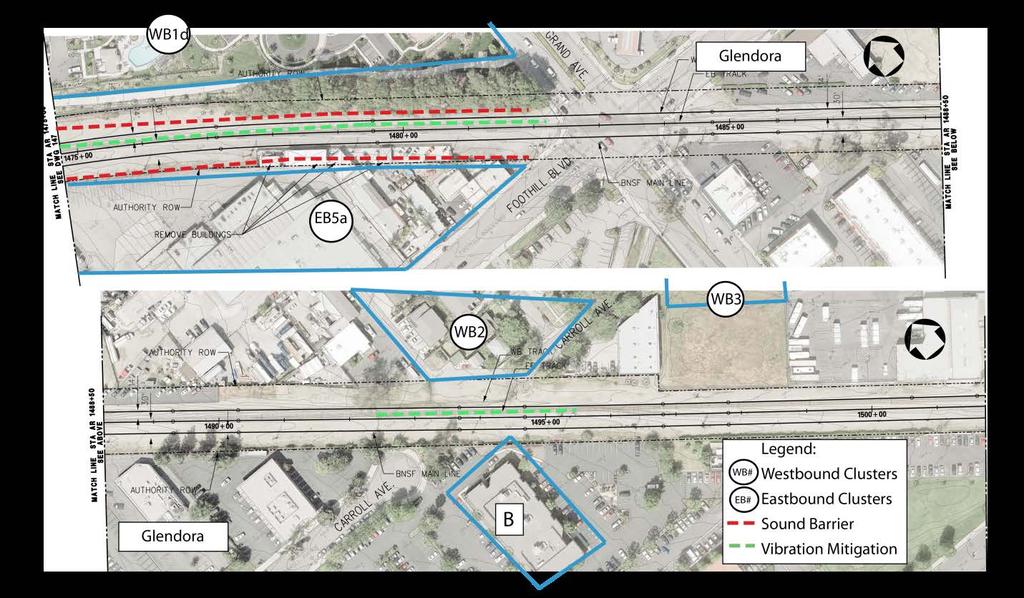
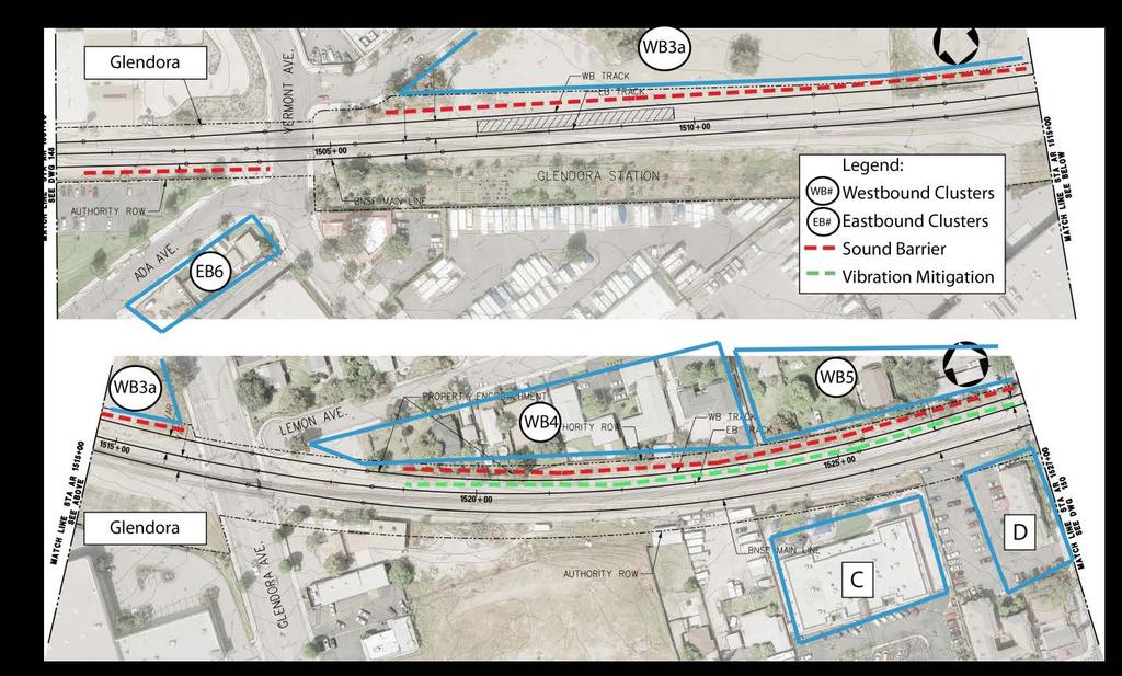
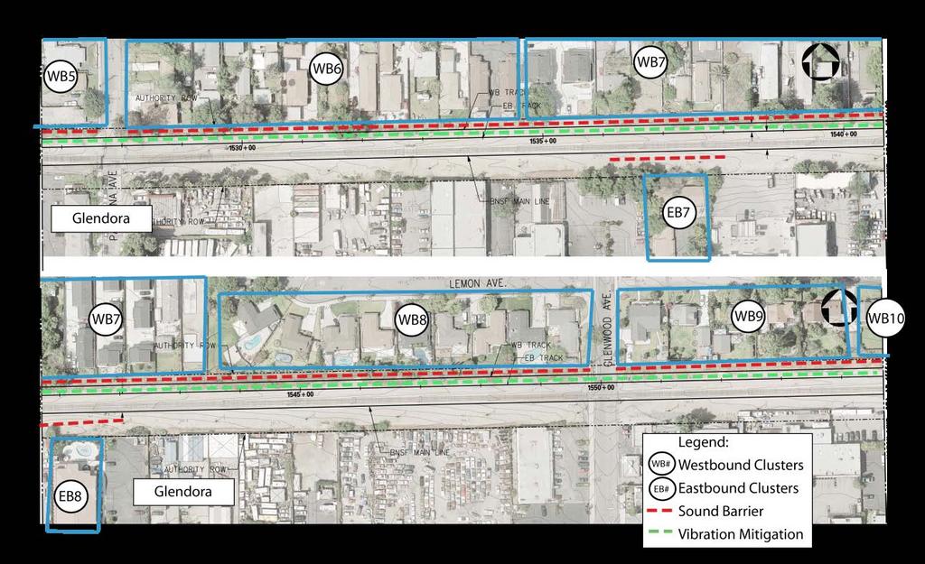
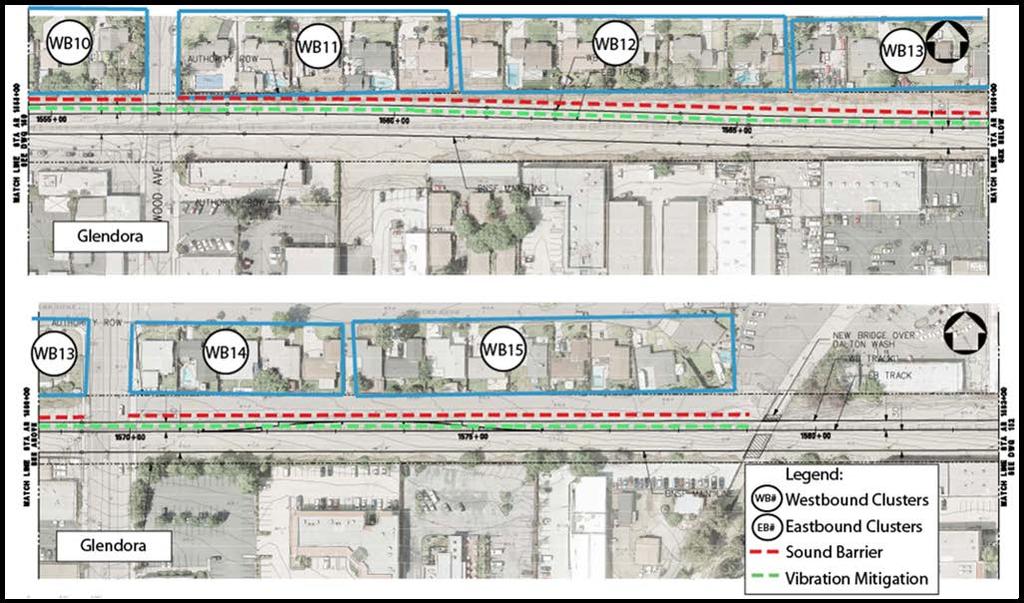
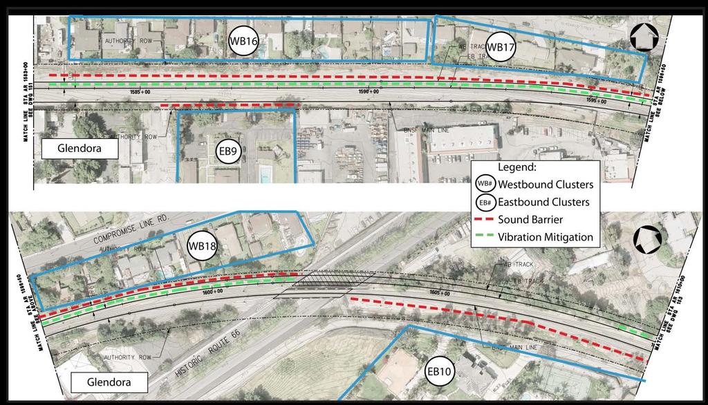
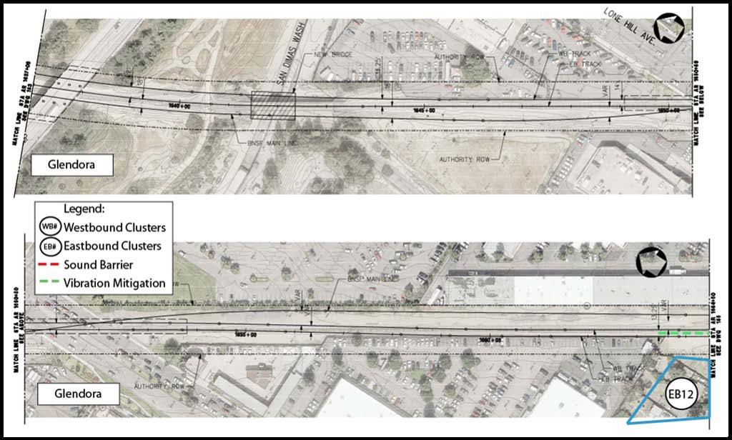
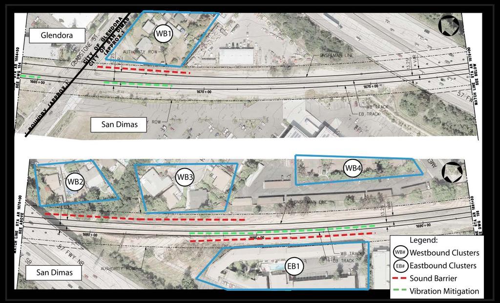
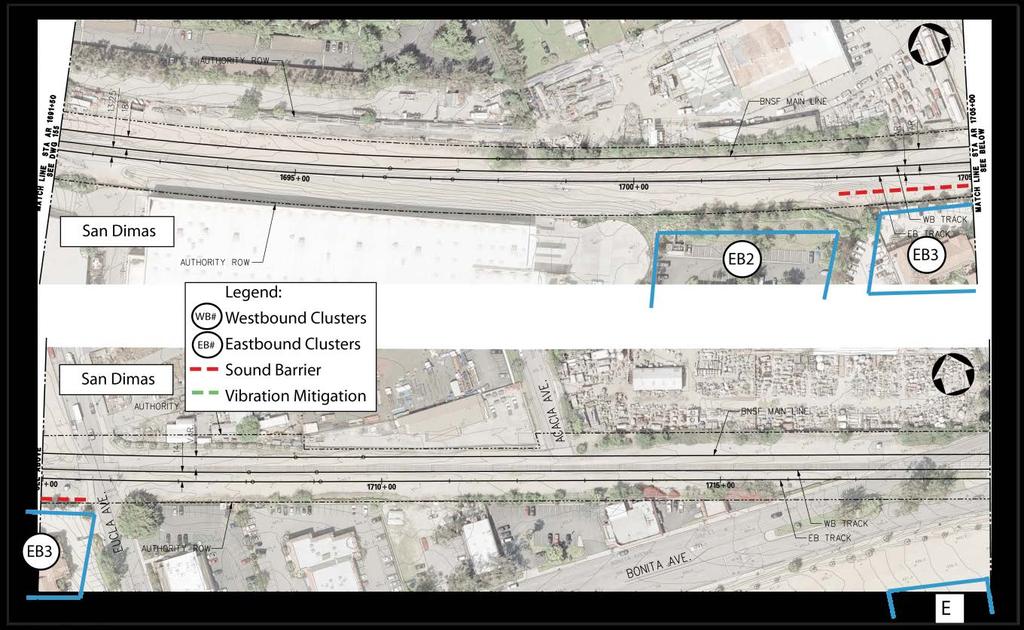
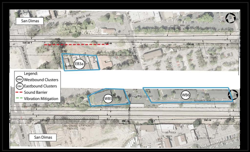
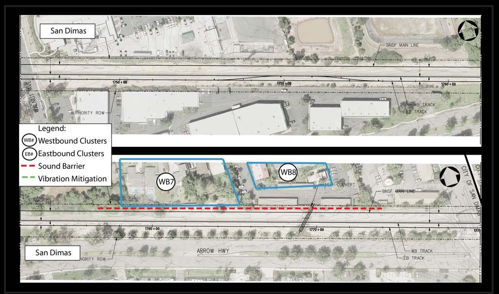
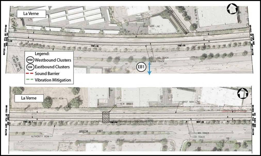
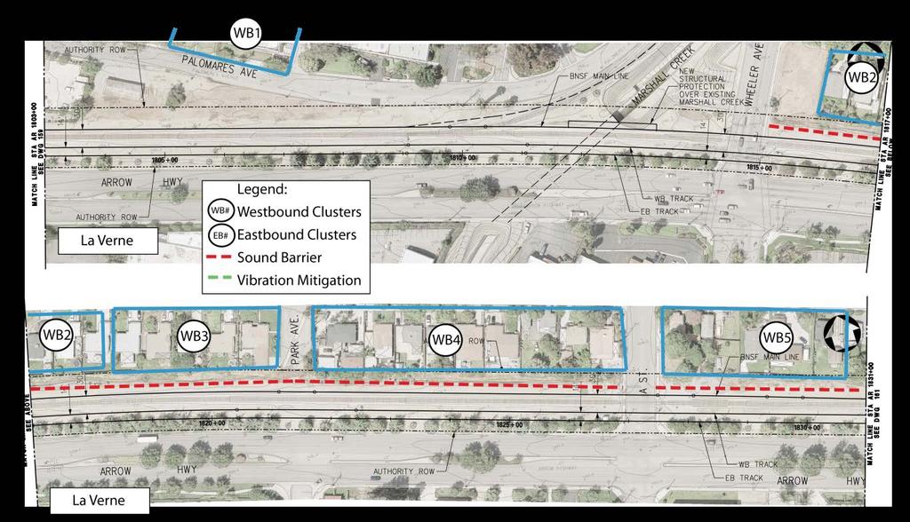
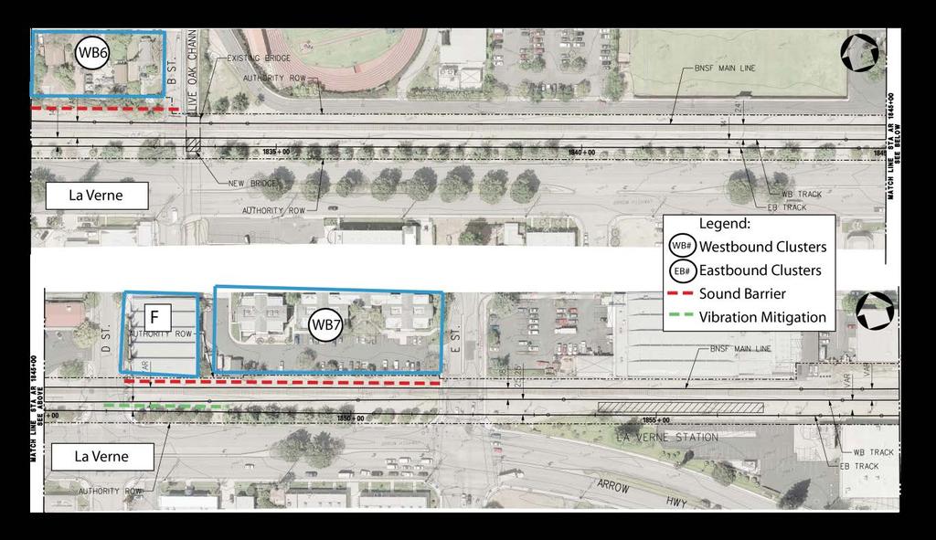
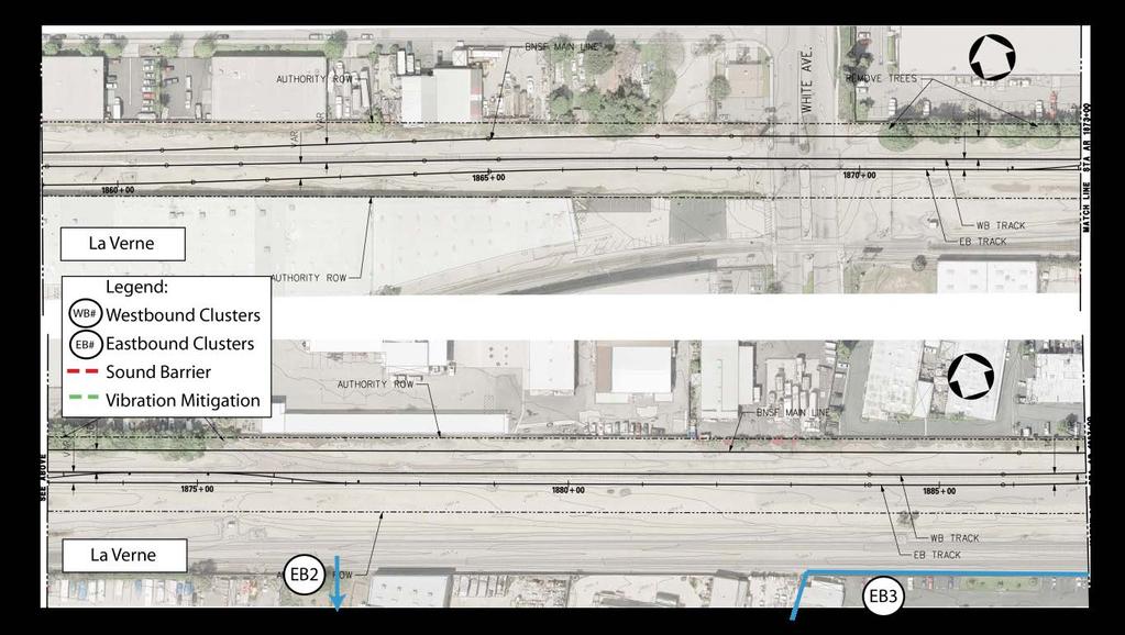
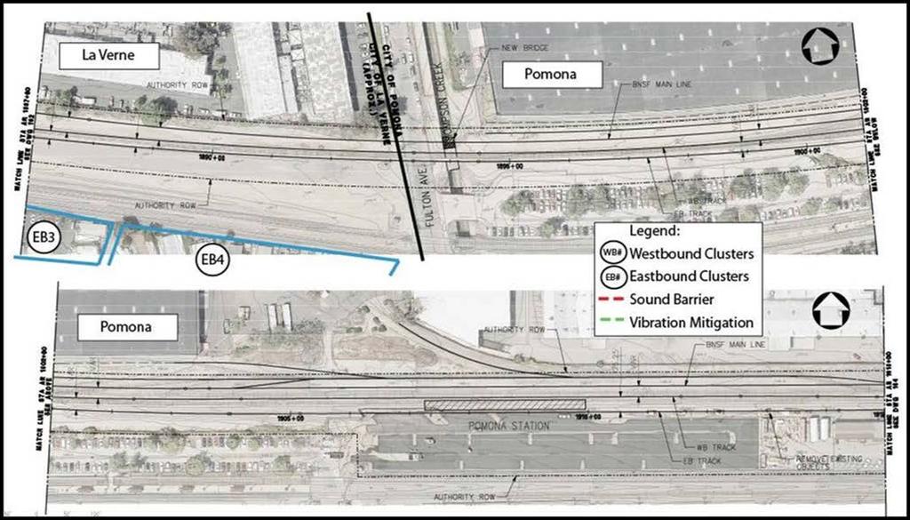
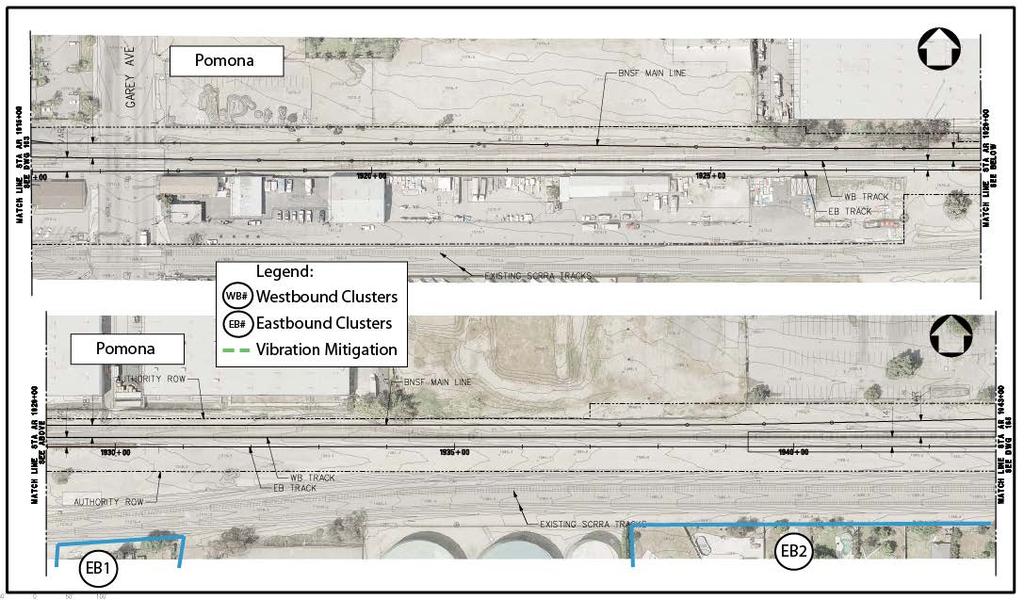
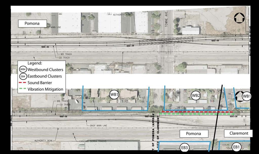
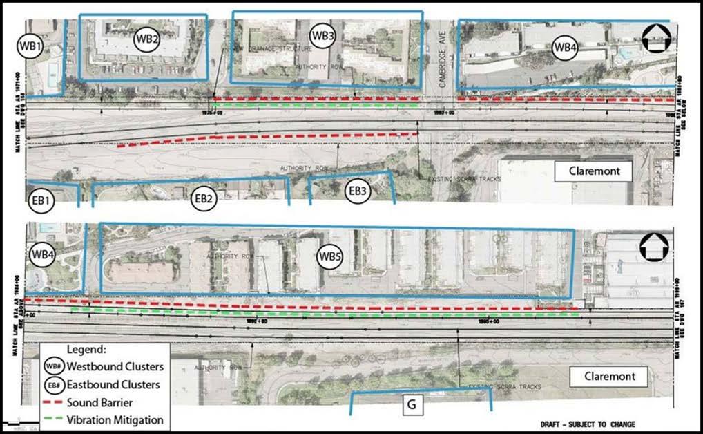
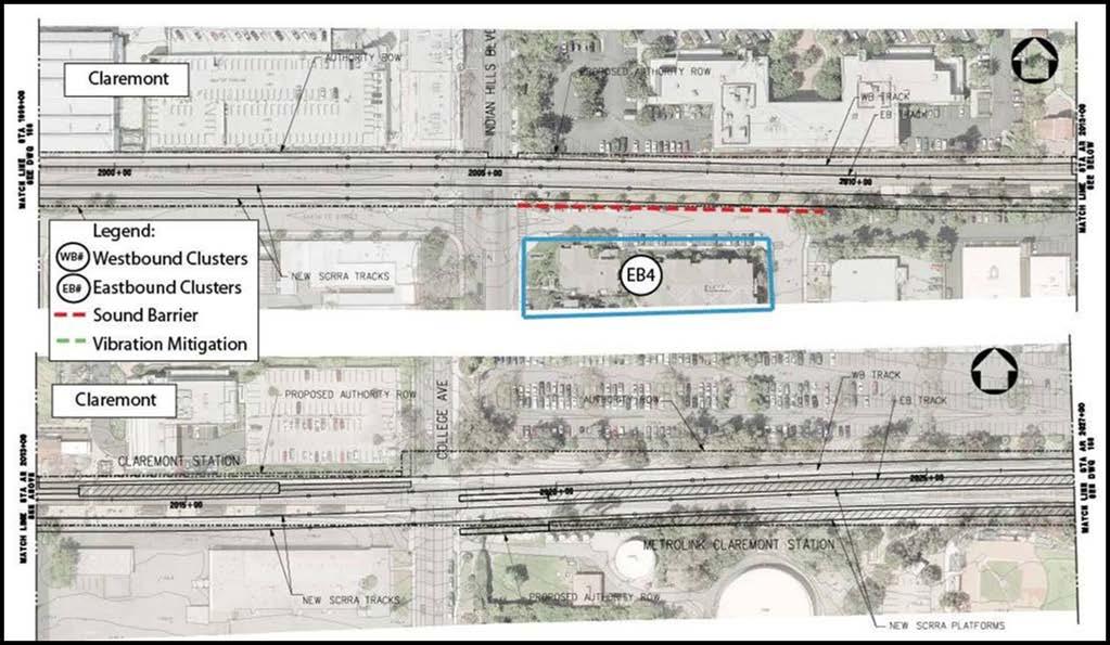
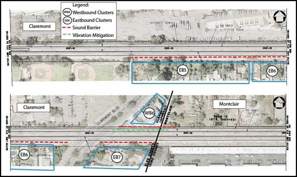
1 Page 80 Noise Barriers This is a common approach to reduce noise impacts from surface transportation sources. The primary requirements for an effective noise barrier are (1) the barrier must be high enough and long enough to break the line-of-sight between the sound source and the receiver; (2) the barrier must be of an impervious material with a minimum surface density of 4 lb/sq. ft.; and (3) the barrier must not have any gaps or holes between the panels or at the bottom. Because numerous materials meet these requirements, the selection of materials for noise barriers is usually dictated by aesthetics, durability, cost, and maintenance considerations. Building Sound Insulation Sound insulation of residences and institutional buildings improve the outdoor-to-indoor noise reduction. Although this approach has no effect on noise in exterior areas, it may be the best choice for sites where noise barriers are not feasible or desirable, for buildings where indoor sensitivity is of most concern, or where the horn noise dominates the noise environment. Substantial improvements in building sound insulation (approximately 5 to 10 dba) can often be achieved by adding an extra layer of glazing to the windows, by sealing any holes in exterior surfaces that act as sound leaks, and by providing forced ventilation and air-conditioning so windows do not need to be opened for ventilation. Train Horns The Federal Railroad Administration (FRA) regulations require all trains operating on the national rail system to sound horns as they approach an at-grade rail/roadway crossing. In 2005, the FRA finalized a horn rule that provides the opportunity to mitigate the effects of train horn noise by establishing quiet zones. The FRA may grant a quiet zone if the affected jurisdiction agrees to implement supplemental safety measures such as four quadrant gates. If the application is approved, freight trains are not required to sound their horns as they approach at-grade crossings. Impact predictions and proposed mitigation are based on October 2011 designs that are subject to further design refinement. During Final Design, data that affects the impact predictions may change, such as the precise locations and grade of rails, switch locations, and the placement of grade crossing warning devices. Accordingly, the impacts and mitigation measures are subject to refinement as well. In particular, the heights of the sound walls and locations where sound insulation is recommended will change if quiet zones are approved by the FRA for at-grade crossings. The recommended primary mitigation measure is construction of noise barriers to shield areas where impact is predicted. Table 33 indicates the approximate noise barrier locations, lengths, side of track, and the clusters they will mitigate. The general location of the sound barriers are also indicated in the cluster drawings presented in Appendix B. The recommended heights for the sound barriers assume that building insulation will be applied to any second-story windows at residences where noise impact is predicted, and that the source height of BNSF horn noise is 10 feet. Table 33: Recommended Locations for Sound Barriers City Wall No. Eng. Station Direction 1 Length Start End (ft) Height 2 (ft) Clusters Mitigated Glendora 1 WB WB 1 Glendora 2 WB WB 1a, 1b, 1c, 1d Glendora 3 WB ,150 8 WB 3a Glendora 4 WB WB 4, 5
2 Page 81 Glendora 5 WB ,200 8 WB 6, 7, 8 Glendora 6 WB WB 9, 10 Glendora 7 WB , WB 11, 12, 13 Glendora 8 WB WB 14, 15 Glendora 9 WB ,850 6 WB 16, 17, 18 Glendora 10 WB , WB 19, 20 Glendora 11 EB ,800 6 EB 1, 2 Glendora 12 EB EB 3 Glendora 13 EB EB 4, 5 Glendora 14 EB , EB 5a Glendora 15 EB EB 6 Glendora 16 EB EB 7 Glendora 17 EB EB 8 Glendora 18 EB EB 9 Glendora 19 EB EB 10 Glendora 20 EB EB 11 Total Length, Glendora (ft) 20,725 San Dimas 1 WB WB 1 San Dimas 2 WB WB 2, 3 San Dimas 3 WB WB 7, 8 San Dimas 4 EB EB 1 San Dimas 5 EB EB 3 San Dimas 6 EB EB 3a Total Length, San Dimas (ft) 2,900 La Verne 1 WB ,175 6 WB 1, 2, 3, 4 La Verne 2 WB WB 5, 6 La Verne 3 WB WB 7, F (Cat. 3) Total Length, La Verne (ft) 2,450 Pomona 1 WB WB 2 Total Length, Pomona (ft) 400 Claremont 1 WB WB 3 Claremont 2 WB ,725 8 WB 4, 5 Claremont 3 WB WB 6 Claremont 4 EB EB 2, 3 Claremont 5 EB EB 4 Claremont 6 EB , EB 5, 6 Claremont 7 EB EB 7 Total Length, Claremont (ft) 5,125 Total Length, All Cities (ft) 31,600
3 Page 82 Source: ATS Consulting, 2011 Notes: Heights and lengths of the sound walls are subject to design refinements. Heights may be significantly altered if quiet zones waivers are granted for at-grade crossings. 1 EB = towards Montclair (south side of tracks); WB = towards Azusa (north side of tracks) 2 Height above the top-of-rail Sound walls must stop at intersections, reducing their effectiveness at grade crossings because of noise leaks around the ends of the walls. In addition, it is not feasible or cost effective for noise barriers to protect some second floors of noise-sensitive receivers. The recommended mitigation measure in these instances is sound insulation of the building. Table 34 indicates the locations where sound insulation for second stories is recommended. Sound insulation is recommended for all second-story windows facing the tracks within the cluster identified. Table 35 indicates the locations where sound insulation is recommended for sensitive receivers near atgrade crossings Improved sound insulation for windows and doors that would be affected by the sound leak around the ends of sound barriers at intersections is one mitigation approach. An alternative approach for noise mitigation at a grade-crossing is to use transparent panels for the sound wall. This approach has been used on Phase 1 of the Exposition Corridor project to mitigate noise impacts with a barrier while maintaining a visual line of sight. Policies for the implementation of residential sound insulation can be based on policies that have been used by other transit systems including TriMet in Portland, Oregon and Sound Transit in Seattle. The approach in Portland and Seattle is to consider sound insulation for residences where the interior noise levels exceed the US Department of Housing and Urban Development (HUD) maximum allowable interior noise level of 45 dba L dn and the improvements will result in at least 5 decibels of noise reduction. The implementation of the policy would include indoor noise testing and analysis to determine the appropriate improvements for each residence. However, implementation of sound insulation requires permission of property owners to allow access to the interior of their properties for both noise measurements and improvements. Table 34: City Recommended Locations for Sound Insulation of Second Stories Cluster Glendora WB 4 Glendora WB 6 Glendora WB 9 Glendora WB 10 Glendora WB 20 Glendora EB 1 Glendora EB 3 Glendora EB 4 Glendora EB 7
4 Page 83 Table 34: City Recommended Locations for Sound Insulation of Second Stories Cluster Claremont WB 5 Claremont WB 6 Claremont EB 4 Claremont EB 6 Claremont EB 7 Source: ATS Consulting, 2011 Notes: Sound insulation is recommended for all second story windows within the cluster. Table 35: Recommended Locations for Sound Insulation near Grade Crossings City Cluster Cross Street Glendora WB 5 Pasadena Avenue Glendora WB 6 Pasadena Avenue Glendora WB 8 Glenwood Avenue Glendora WB 9 Glenwood Avenue Glendora WB 10 Elwood Avenue Glendora WB 11 Elwood Avenue Glendora WB 13 Lorraine Avenue Glendora WB 14 Lorraine Avenue Glendora EB 3 Barranca Avenue Glendora EB 4 Barranca Avenue San Dimas WB 1 Gladstone Street La Verne WB 2 Wheeler Avenue La Verne WB 3 Wheeler Avenue La Verne WB 4 A Street La Verne F (Category 3) D Street Claremont WB 3 Cambridge Avenue Claremont WB 4 Cambridge Avenue Claremont EB 3 Cambridge Avenue Claremont EB 4 Indian Hill Source: ATS Consulting, 2011 Notes: The engineering station identifies the cluster at the intersection, not the particular building where insulation should be applied.
5 Page 84 Implementing a quiet zone requires cooperation by all jurisdictions involved with the grade crossing and is contingent on approval by the FRA. Requirements for a quiet zone waiver include installation of supplemental safety measures such as four quadrant gates that may already be included as part of the project. If quiet zones were approved, it would eliminate the need for some of the sound walls listed in Table 33 and some of the sound insulation recommended Table 35. The at-grade crossings where petition for quiet zone status is recommended are presented in Table 36. Table 36: Recommended At-Grade Crossings to Petition for Quiet Zone City Cross Street Clusters Mitigated Glendora Barranca Avenue EB 3, 4 Glendora Pasadena Avenue WB 5, 6 Glendora Glenwood Avenue WB 8, 9 Glendora Elwood Avenue WB 10, 11 Glendora Lorraine Avenue WB 13, 14 San Dimas Gladstone Street WB 1 La Verne Wheeler Avenue WB 2, 3 La Verne A Street WB 5 La Verne D Street F (Category) Claremont Cambridge Avenue WB 3, WB 4, EB 3 Claremont Indian Hill Boulevard EB 4 Claremont Claremont Boulevard WB 6, EB 6, EB 7 Source: ATS Consulting, 2011 Notes: Freight trains begin sounding their horns 1/4 mile before an intersection; a quiet zone will improve the noise environment at all clusters within a 1/4 mile of an at-grade crossing A number of residential areas along the right-of-way have existing barriers or privacy walls that act as sound barriers. The noise impact analysis assumed that these existing walls would not provide any noise reduction because it is not possible to assess the effectiveness of each wall without individual site visits and surveys. Many of the walls may not be effective as noise barriers due to construction, height, or gaps in the wall. During the final design of the project, the effectiveness of the existing barriers/privacy walls can be assessed and incorporated into final mitigation measures. It may be determined that a number of the existing barriers are effective sound walls, or that some may need to be only repaired or raised slightly to provide the appropriate level of noise reduction. 6.2 Operational Vibration The vibration analysis identified Category 2 (residential) land uses that exceed the FTA thresholds for vibration levels. Mitigation measures that may be implemented to reduce vibration levels to below the FTA thresholds are described below:
6 Page 85 Ballast Mats A ballast mat consists of a pad made of rubber or rubber-like material placed on the subballast with normal ballast, ties, and rail on top. The reduction in groundborne vibration provided by a ballast mat is strongly dependent on the frequency content of the vibration and the design and support of the mat. Depending on the soil properties, an asphalt or concrete layer under the ballast may be required. Tire Derived Aggregate (TDA) TDA consists of a resilient layer of shredded tires or recycled rubber chips placed beneath the sub-ballast layer of standard open ballast and tie track. This mitigation method provides results similar to ballast mats and would be strongly dependent on the frequency content of the vibration. This is a relatively new vibration mitigation approach that has been successfully implemented by Denver Regional Transit and the Santa Clara Valley Transportation Authority. In both Santa Clara Valley and Denver, 12-inch layers of TDA were installed. Relocation of Crossovers or Special Trackwork The special trackwork at crossover locations increase vibration by about 10 db. Relocating crossovers away from residential areas will help to eliminate impacts. If crossovers cannot be relocated away from residential areas, another approach is to use specially designed low-impact frogs in place of standard rigid frogs. Examples of low-impact frogs include flange-bearing, spring-rail, and moveable point frogs. Floating-Slab Track The track is constructed on a concrete slab that is supported by resilient elements (either pads 8 to 12 inches thick or a continuous resilient mat). This type of track construction is very expensive and is typically used only where substantial vibration mitigation is needed. Mitigation is considered for all clusters that exceed the vibration threshold for light-rail operations. Table 37 presents the recommended vibration mitigation locations, types, and lengths for the Azusa to Montclair corridor. The majority of the vibration mitigation is in Glendora (15,900 feet). The residences along Lemon Avenue in Glendora (between Pasadena Avenue and the Dalton Wash) are located close to the LRT tracks (within 50 feet), and the estimated attenuation from TDA or ballast mat is insufficient to reduce the predicted vibration to below the FTA impact thresholds. Floating slab track is capable of providing the necessary attenuation. Table 37: City Eng. Station Length (ft) Start End Recommended Locations for Vibration Mitigation Mitigation Type Clusters Mitigated Glendora ,350 Ballast Mat/TDA EB 1-5 Glendora ,400 Ballast Mat/TDA EB 5a Glendora Ballast Mat/TDA WB 2 Glendora ,100 Floating Slab WB 4-15, EB 7 Glendora ,800 Ballast Mat/TDA WB 16-18, EB 9 Glendora ,800 Ballast Mat/TDA WB 19-20, EB Glendora Ballast Mat/TDA EB 12 Total Length Glendora (ft) 15,900 San Dimas Ballast Mat/TDA WB 1
7 Page 86 San Dimas Floating Slab EB 1 Total Length San Dimas (ft) 900 Pomona Ballast Mat/TDA WB 2 Total Length Pomona (ft) 450 Claremont Ballast Mat/TDA WB 3 Claremont ,150 Ballast Mat/TDA WB 5 Claremont Ballast Mat/TDA WB 6 Total Length Claremont (ft) 1,900 Total Ballast Mat/TDA (all cities): 12,450 Total Floating Slab (all cities): 6,700 Source: ATS Consulting, 2011 Notes: It is assumed that mitigation will be placed under both near and far tracks. In addition to the mitigation recommended in Table 37, low-impact frogs should be installed at the crossovers in Glendora. These crossovers are located adjacent to the single-family residences in Glendora (westbound clusters 14 and 15) between engineering stations and Low-impact frogs would provide vibration attenuation at these residences. Vibration impact was also identified from the relocation of the Metrolink tracks at Claremont eastbound clusters 4 and 7. A potential mitigation measure is the installation of ballast mat or TDA under both Metrolink tracks. Table 38: Recommended Locations for Vibration Mitigation, Metrolink Tracks City Eng. Station Length (ft) Start End Mitigation Type Clusters Mitigated Claremont Ballast Mat/TDA EB 4 Claremont Ballast Mat/TDA EB 7 Source: ATS Consulting, 2011 Notes: It is assumed that mitigation will be placed under both near and far SCRRA tracks. The mitigation recommendations in Table 37 and Table 38 will reduce the predicted vibration levels to below the FTA impact threshold at all but three of the sensitive receivers. Considering the conservative assumptions in both the operational vibration and mitigation predictions, it is likely that the vibration level with the recommended mitigation would be below the FTA impact threshold at those three locations. Further analysis during final design is recommended to confirm that the recommended mitigation is sufficient and reasonable. The three locations with residual impact are presented in Table 39. Two of the sensitive receivers with residual impact (Glendora WB6 and San Dimas EB1) are located within 15 feet of the proposed light-rail tracks. The closest vibration propagation data was collected at 25
8 Page 87 feet and was extrapolated to 15 feet to make the vibration predictions. The extrapolation may be overpredicting the vibration level at such a close distance. The predicted vibration levels at Glendora WB18 is equal to the FTA impact threshold of 72 VdB with mitigation from TDA or ballast mat. A floating slab would reduce the vibration levels to below the impact threshold. However, considering the expense for a floating slab compared to TDA or ballast mat and the conservative assumptions in the prediction process, it would be unreasonable to install a floating slab track design at that location where the impact threshold is exceeded by less than 1 db. Table 39: Residual Vibration Impacts City Cluster Distance (ft) Mitigation Type Predicted Level with Mitigation Glendora WB6 12 Floating Slab 76 VdB at 50 Hz Glendora WB18 44 TDA/Ballast Mat 72 VdB at 31.5 Hz San Dimas EB1 14 Floating Slab 78 VdB at 31.5 Hz Source: ATS Consulting 2011 There are several locations in the corridor where mitigation is recommended, but the predicted vibration level only slightly exceeds the FTA vibration impact threshold. During final design, the vibration predictions at these residences should be revisited to ensure that vibration mitigation is necessary. In addition, the vibration predictions at the institutional land use in La Verne and vibration impact from the Metrolink tracks in Claremont should also be revisited to ensure the vibration mitigation is necessary. The analysis used the worst-case LSTM from the measurement results, and the actual LSTM at some of the clusters may be below values used in the predictions. The locations recommended for further study during final design are presented in Table 40. Table 40: Vibration Impacts Recommended for Further Study City Cluster Distance (ft) Mitigation Type Predicted Level without Mitigation Glendora EB5a 75 TDA/Ballast Mat 74 VdB at 31.5 Hz Glendora EB10, EB12 94 TDA/Ballast Mat 72 VdB at 31.5 Hz Glendora EB11 84 TDA/Ballast Mat 73 VdB at 31.5 Hz San Dimas WB1 50 TDA/Ballast Mat 73 VdB at 31.5 Hz La Verne F 34 TDA/Ballast Mat 78 VdB at 50 Hz Pomona WB2 64 TDA/Ballast Mat 72 VdB at 31.5 Hz Claremont EB4 60 TDA/Ballast Mat 72 VdB at 50 Hz for Metrolink Claremont EB7 44 TDA/Ballast Mat 75 VdB at 50 Hz for Metrolink Source: ATS Consulting 2011
9 Page Construction Noise Without noise mitigation, construction of the project is expected to generate noise levels that exceed any thresholds imposed by the Construction Authority in areas near residences. Measures to reduce construction noise levels include: Noise Control Plan: The contractor should be required to develop a Noise Control Plan that demonstrates how he will achieve the appropriate noise limits. The plan should include measurements of existing noise, a list of the major pieces of construction equipment that will be used, and predictions of the noise levels at the closest sensitive receivers (including residences, hotels, schools, churches, temples, and similar facilities). The noise control plan should be approved by the Metro Gold Line Foothill Extension Construction Authority prior to initiating construction. Alternative Construction Procedures: Where the construction cannot be performed in accordance with the requirement of the noise limits, the contractor should be required to investigate alternative construction measures that would result in lower sound levels. Also, the contractor should be required to conduct noise monitoring to demonstrate compliance with contract noise limits. Best Management Practices: The contractor should be required to use the following best management practices for noise abatement wherever practical: - Use specialty equipment with enclosed engines and/or high performance mufflers when feasible. The contractor shall locate equipment and staging areas as far from noise sensitive receivers as possible. - Limit unnecessary idling of equipment. - Install temporary noise barriers as needed and where feasible. - Reroute construction related truck traffic away from residential streets to the extent permitted by the relevant municipality. - Avoid impact pile driving where possible. Where geological conditions permit, use quieter alternatives such as drilled piles or a vibratory pile driver. Specific measures to be employed to mitigate construction noise impacts would be developed by the contractor. In addition, the Construction Authority should be available during construction to discuss and address noise complaints from residents and business owners. 6.4 Construction Vibration It is unlikely that vibration from construction activities will exceed the thresholds for minor cosmetic damage to buildings. In the event that equipment producing high levels of vibration may approach those limits, the noise control plan should also include measures to minimize vibration impacts during construction. Also, representatives from the Construction Authority should be available to discuss
10 Page 89 vibration related complaints and take appropriate action to minimize the intrusion. Appropriate vibration mitigation measures include: Minimizing the use of tracked vehicles, Avoiding vibratory compaction, and Vibration monitoring near residences to ensure thresholds are not exceeded.
11 Page 90 APPENDIX A. FUNDAMENTAL CONCEPTS OF NOISE AND VIBRATION Noise Fundamentals Sound is mechanical energy transmitted by pressure waves in a compressible medium such as air. Noise is generally defined as unwanted or excessive sound. Sound can vary in intensity by over one million times within the range of human hearing. Therefore, a logarithmic scale, known as the decibel scale (db), is used to quantify sound intensity and compress the scale to a more convenient range. Sound is characterized by both its amplitude and frequency (or pitch). The human ear does not hear all frequencies equally. In particular, the ear deemphasizes low and very high frequencies. To better approximate the sensitivity of human hearing, the A-weighted decibel scale has been developed. A- weighted decibels are abbreviated as dba. On this scale, the human range of hearing extends from approximately 3 dba to around 140 dba. As a point of reference, Figure 32 includes examples of A- weighted sound levels from common indoor and outdoor sounds. Figure 32: Typical Indoor and Outdoor Noise Levels Using the decibel scale, sound levels from two or more sources cannot be directly added together to determine the overall sound level. Rather, the combination of two sounds at the same level yields an increase of 3 db. The smallest recognizable change in sound level is approximately 1 db. A 3-dB increase in the A-Weighted sound level is generally considered perceptible, whereas a 5-dB increase is readily perceptible. A 10-dB increase is judged by most people as an approximate doubling of the perceived loudness.
12 Page 91 The two primary factors that reduce levels of environmental sounds are increasing the distance between the sound source and the receiver and having intervening obstacles such as walls, buildings, or terrain features that block the direct path between the sound source and the receiver. Factors that act to make environmental sounds louder include moving the sound source closer to the receiver, sound enhancements caused by reflections, and focusing caused by various meteorological conditions. Following are brief definitions of the measures of environmental noise used in this study: Maximum Sound Level (L max ): L max is the maximum sound level that occurs during an event such as a train passing. For this analysis L max is defined as the maximum sound level using the slow setting on a standard sound level meter. Equivalent Sound Level (L eq ): Environmental sound fluctuates constantly. The equivalent sound level (L eq ) is the most common means of characterizing community noise. L eq represents a constant sound that, over a specified period of time, has the same sound energy as the timevarying sound. L eq is used by the FTA to evaluate noise effects at institutional land uses, such as schools, churches, and libraries, from proposed transit projects. Day-Night Sound Level (L dn ): L dn is basically a 24-hour L eq with an adjustment to reflect the greater sensitivity of most people to nighttime noise. The adjustment is a 10 db penalty for all sound that occurs between the hours of 10:00 p.m. to 7:00 a.m. The effect of the penalty is that, when calculating L dn, any event that occurs during the nighttime is equivalent to ten occurrences of the same event during the daytime. L dn is the most common measure of total community noise over a 24-hour period and is used by the FTA to evaluate residential noise effects from proposed transit projects. L XX : This is the percent of time a sound level is exceeded during the measurement period. For example, the L 99 is the sound level exceeded during 99 percent of the measurement period. For a 1-hour period, L 99 is the sound level exceeded for all except 36 seconds of the hour. The tables of the hourly noise levels in Appendix B include L 1, L 33, L 50, and L 99, the sound levels exceeded 1 percent, 33 percent, 50 percent and 99 percent of the hour. L 1 represents typical maximum sound levels, L 33 is approximately equal to L eq when free-flowing traffic is the dominant noise source, L 50 is the median sound level, and L 99 is close to the minimum sound level. Sound Exposure Level (SEL): SEL is a measure of the acoustic energy of an event such as a train passing. In essence, the acoustic energy of the event is compressed into a 1-second period. SEL increases as the sound level of the event increases and as the duration of the event increases. It is often used as an intermediate value in calculating overall metrics such as L eq and L dn. Sound Transmission Class (STC): STC ratings are used to compare the sound insulating effectiveness of different types of noise barriers, including windows, walls, etc. Although the amount of attenuation varies with frequency, the STC rating provides a rough estimate of the transmission loss from a particular window or wall. Vibration Fundamentals One potential community effect from the proposed project is vibration that is transmitted from the tracks through the ground to adjacent houses. This is referred to as groundborne vibration. When evaluating human response, groundborne vibration is usually expressed in terms of decibels using the root mean
13 Page 92 square (RMS) vibration velocity. RMS is defined as the average of the squared amplitude of the vibration signal. To avoid confusion with sound decibels, the abbreviation VdB is used for vibration decibels. All vibration decibels in this report use a decibel reference of 1 micro-inch/second (µin/sec.). 6 The potential adverse effects of rail transit groundborne vibration are as follows: Perceptible Building Vibration: This is when building occupants feel the vibration of the floor or other building surfaces. Experience has shown that the threshold of human perception is around 65 VdB and that vibration that exceeds 75 to 80 VdB may be intrusive and annoying to building occupants. Rattle: The building vibration can cause rattling of items on shelves and hanging on walls, and various different rattle and buzzing noises from windows and doors. Reradiated Noise: The vibration of room surfaces radiates sound waves that may be audible to humans. This is referred to as groundborne noise. When audible groundborne noise occurs, it sounds like a low-frequency rumble. For a surface rail system such as the proposed build alternatives, the groundborne noise is usually masked by the normal airborne noise radiated from the transit vehicle and the rails. Damage to Building Structures: Although it is conceivable that vibration from a light-rail system could cause damage to fragile buildings, the vibration from light-rail transit systems is usually one to two orders of magnitude below the most restrictive thresholds for preventing building damage. Hence the vibration effect criteria focus on human annoyance, which occurs at much lower amplitudes than does building damage. Vibration is an oscillatory motion that can be described in terms of the displacement, velocity, or acceleration of the motion. The response of humans to vibration is very complex. However, the general consensus is that for the vibration frequencies generated by passenger trains, human response is best approximated by the vibration velocity level. Therefore, vibration velocity has been used in this study to describe train-generated vibration levels. When evaluating human response, groundborne vibration is usually expressed in terms of decibels using the root mean square (RMS) vibration velocity. RMS is defined as the average of the squared amplitude of the vibration signal. To avoid confusion with sound decibels, the abbreviation VdB is used for vibration decibels. All vibration decibels in this report use a decibel reference of 1 µin/sec. Figure 33 shows typical vibration levels from rail and non-rail sources as well as the human and structure response to such levels. 6 One µin/sec= 10-6 in/sec.
14 Page 93 Figure 33: Typical Vibration Levels Although there has been relatively little research into human and building response to groundborne vibration, there is substantial experience with vibration from rail systems. In general, the collective experience indicates that: It is rare that groundborne vibration from transit systems results in building damage, even minor cosmetic damage. The primary consideration therefore is whether vibration will be intrusive to building occupants or will interfere with interior activities or machinery. The threshold for human perception is approximately 65 VdB. Vibration levels in the range of 70 to 75 VdB are often noticeable but acceptable. Beyond 80 VdB, vibration levels are often considered unacceptable. For human annoyance, there is a relationship between the number of daily events and the degree of annoyance caused by groundborne vibration. The FTA Guidance Manual includes an 8 VdB higher impact threshold if there are fewer than 30 events per day and a 3 VdB higher threshold if there are fewer than 70 events per day. Often it is necessary to determine the contribution at different frequencies when evaluating vibration or noise signals. The 1/3-octave band spectrum is the most common procedure used to evaluate frequency components of acoustic signals. The term octave has been borrowed from music where it refers to a span of eight notes. The ratio of the highest frequency to the lowest frequency in an octave is 2:1. For a 1/3-octave band spectrum, each octave is divided into three bands where the ratio of the lowest frequency to the highest frequency in each 1/3-octave band is 2 1/3 :1 (1.26:1). An octave consists of three 1/3 octaves.
15 Page 94 The 1/3-octave band spectrum of a signal is obtained by passing the signal through a bank of filters. Each filter excludes all components except those that are between the upper and lower range of one 1/3-octave band. The FTA Guidance Manual is a good reference for additional information on transit noise and vibration and the technical terms used in this section.


16 Page 95 APPENDIX B. CLUSTER DIAGRAMS
17 Page 96
18 Page 97
19 Page 98
20 Page 99
21 Page 100
22 Page 101
23 Page 102
24 Page 103
25 Page 104
26 Page 105
27 Page 106
28 Page 107 APPENDIX C. Force Density Level (FDL) SUPPLEMENTAL MEASUREMENT DATA The Force Density Level (FDL) used in this vibration analysis for LRT vibration predictions is based on measurements made in the historic Cornfields State Park along the operational Phase 1 of the Metro Gold Line in 2008 for the Metro Expo Phase 1 vibration analysis. Previous FDL measurements were made in 2001 and Following is a description of each of the FDL tests: DEIR FDL (2001 measurements): Force density measurements were taken by Harris, Miller, Miller, and Hanson (HMMH) along Phase I of the Gold Line with the Siemens (P2000) vehicle. Further information about the measurements is available in the DEIR FEIR FDL (2004 measurements): The FDL used in the 2007 FEIR vibration analysis was the log average of the measured 2005 DEIR FDL and an FDL measured from a prototype Siemens (P2000) vehicle along the Bixby Knolls section of the Long Beach Blue Line in Cornfield FDL (2008 measurements): Force density measurements were taken by ATS Consulting in 2008 at the Los Angeles State Historic Park (The Cornfield) just north of the Chinatown Station of the Gold Line Phase 1. The test included measurements of the Siemens (P2000) vehicle and the Ansaldobreda (P2550) vehicle. The two vehicle types showed similar vibration levels and were combined into one FDL. This test was conducted as part of a detailed vibration analysis for the Expo Phase 1 line in Los Angeles. Additional vibration measurements of both vehicle types were made at the same location in October 2010 to confirm there have been no significant changes to vibration levels since the 2008 test. The FDLs from the three different measurements are shown in Figure 34. The FDL used in this analysis, the Cornfield FDL, is shown bolded in blue. The Cornfield FDL from the October 2008 test was used for the vibration predictions presented in this analysis for the following reasons: The 2005 DEIR FDL has a peak in the 63 Hz 1/3 octave band that is not in the 2007 FEIR or Cornfield FDLs. Because subsequent measurements have not corroborated the peak, it is unlikely to be representative of what will occur on the Gold Line Foothill Extension. The 2007 FEIR FDL was based on measurements on the Blue Line. The FDL for the Foothill Extension Azusa to Montclair will most likely be more similar to measurements taken along the existing Gold Line track. The Cornfield FDL is greater than or similar to the 2007 FEIR FDL across the entire frequency spectrum. Vibration predictions made using the Cornfield FDL are conservative and minimize the chance of underestimating the vibration. The Cornfield FDL is the most up-to date data. The 2007 FEIR and 2005 DEIR data are based on measurements made more than five years ago. The Cornfield FDL is based on measurements of trains traveling at an average speed of 53 mph. If the trains are travelling significantly slower (when they are entering or exiting stations), the FDL will be much lower. To account for the difference in FDL due to lower speeds an adjustment of 20*log(speed/53mph) was used. This is the adjustment recommended in the FTA Guidance Manual to account for fluctuations in the operating speed.
29 Page 108 Figure 34: Comparison of Force Density Levels (FDLs) The FDL is derived by measuring the train vibration (Lv) along an existing section of operational track and subtracting the measured LSTM: FDL = Lv - LSTM. As mentioned above, the FDL for the Cornfields 2008 measurement was made along Phase 1 of the Metro Gold Line. The Gold Line currently operates with two different vehicles: Siemans and Ansaldobreda. Vibration measurements from the two vehicles showed similar results and were combined into one FDL. The measured vibration levels used in the calculation of the FDL are shown in Figure 35 below. The LSTM measured at the same site and also used in the calculation of the FDL is shown in Figure 36.

30 Page 109 Figure 35: Measured Gold Line Train Vibration Levels Figure 36: LSTM at the Cornfields State Park
31 Page 110 The FDL used in the vibration analysis for Metrolink vibration predictions is based on measurements made at vibration propagation test site V-20 in Claremont. Vibration from operating Metrolink trains in the project right-of-way is shown in Figure 37. The FDL for Metrolink trains was derived from those vibration measurements as well as the LSTM results from site V-20. The Metrolink FDL is shown in Figure 38 Figure 37: Measured Vibration Levels from Metrolink Trains in Claremont on the Westbound (WB) and Eastbound (EB) Tracks
32 Page 111 LSTM Measurement Results Figure 38: The FDL for Metrolink Trans The vibration propagation tests were performed at seventeen locations throughout the proposed project corridor. The locations of the tests and the measurement results, sorted by city, are presented in Section 2. This section presents the best-fit and worst-case curves derived from those measurements and applied in the prediction models. Best-fit curves were fit to the data of each 1/3 octave band of the different measurement sites. The best-fit curves were used to compare the results from all of the sites and develop worst-case curves that could be applied throughout the corridor. After inspection of the results, the LSTM results were separated into three groups: Glendora, San Dimas/La Verne, and Pomona/Claremont. The best fit results, presented by city, are shown in Figure 39 through Figure 41 below. A worst case curve was developed for each group by using the highest value in each 1/3 octave band for that group. The worst case curves for each group are shown in Figure 42 below. The worst case curves are used in the vibration prediction models to ensure that the vibration levels are not under predicted at the sensitive receivers.

33 Page 112 Figure 39: Glendora LSTM Best-Fit Results


34 Page 113 Figure 40: La Verne/San Dimas LSTM Best-Fit Results

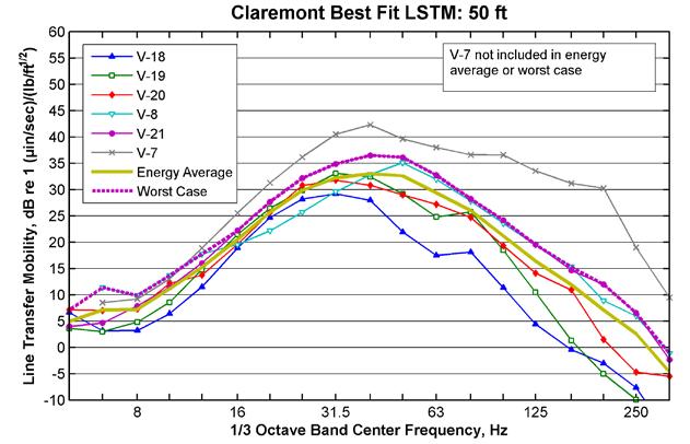
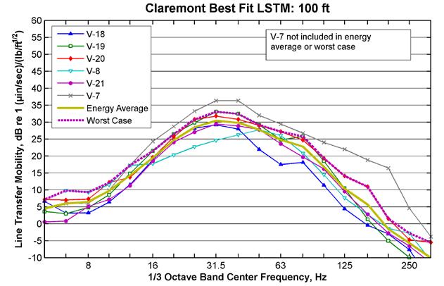
35 Page 114 Figure 41: Pomona/Claremont LSTM Best-Fit Results
36 Page 115 Figure 42: Worst-Case LSTMs Used in Prediction Models
37 Page Indoor Vibration Measurements LSTM measurements were taken indoors at eight residences to assist in estimating the difference between outdoor and indoor vibration levels including any amplification from floor resonances. The LSTM and coherence results from those indoor measurements and the nearest outdoor measurement are shown in Figure 43 through Figure 50. The addresses of the indoor measurements are: 520 Cornell Drive, Arcadia (second story MFR) 1614 Unit D Mayflower Avenue, Monrovia (second story MFR) 1320 Three Ranch Road, Duarte (single story SFR) 824 Unit 22 Pasadena Avenue, Azusa (second story MFR) 412 East Lemon Avenue, Glendora (second floor, rear unit in MFR; vibration site V-13) 444 North Amelia Avenue Unit 31F, San Dimas (second floor unit in MFR; vibration site V-15) 949 Arrow Highway Unit 2, Claremont (first floor of unit in MFR; vibration site V-19) 115 North Mountain Avenue, Claremont (second floor corner unit of MFR; vibration site V-20)
38 Page Figure 43: Arcadia Indoor Measurement LSTM and Coherence Figure 44: Monrovia Indoor Measurement LSTM and Coherence
39 Page Figure 45: Duarte Indoor Measurement LSTM and Coherence Figure 46: Azusa Indoor Measurement LSTM and Coherence
40 Page Figure 47: Glendora Indoor Measurement LSTM and Coherence Figure 48: San Dimas Indoor Measurement LSTM and Coherence
41 Page Figure 49: Claremont (V-19) Indoor Measurement LSTM and Coherence Figure 50: Claremont (V-20) Indoor Measurement LSTM and Coherence
42 Page 121
Table City of Claremont Predicted Vibration Levels for Residential (Category 2) Land Uses
 Land Uses") Table 3.11-19. City of Claremont Predicted Vibration Levels for Residential (Category 2) Land Uses Cluster Number 1 Cross Streets Direction Distance (feet) 2 Train Speed (mph) Threshold (VdB) Predicted
Table 3.11-19. City of Claremont Predicted Vibration Levels for Residential (Category 2) Land Uses Cluster Number 1 Cross Streets Direction Distance (feet) 2 Train Speed (mph) Threshold (VdB) Predicted
Environmental Assessment May 2007
 jurisdictional waters. It is assumed that, at a minimum, a USACE Section 404 Nationwide Permit would be necessary to construct these features. The impacts of the fill into the floodplain cannot be fully
Memo. Summary of Vibration Study and Findings
 Memo Date: Tuesday, November 17, 2015 Project: To: From: Subject: Lindley Avenue to Balboa Boulevard Vibration Study LA Metro Elliott Dick and Tim Casey Vibration Measurement Results Summary of Vibration
WESTSIDE PURPLE LINE EXTENSION PROJECT, SECTION 2 ADVANCED PRELIMINARY ENGINEERING Contract No. PS
 LOS ANGELES COUNTY METROPOLITAN TRANSPORTATION AUTHORITY WESTSIDE PURPLE LINE EXTENSION PROJECT, SECTION 2 ADVANCED PRELIMINARY ENGINEERING Contract No. PS-4350-2000 Beverly Hills High School Master Plan
Northern Branch Corridor DEIS December 2011
 13. Vibration 13.1. Chapter Overview 13.1.1. Introduction This chapter describes applicable vibration standards and criteria and also identifies high-sensitivity resources within the Northern Branch Corridor.
7. BASIC GROUND-BORNE VIBRATION CONCEPTS
 Chapter 7: Basic Ground-Borne Vibration Concepts 7-1 7. BASIC GROUND-BORNE VIBRATION CONCEPTS Ground-borne vibration can be a serious concern for nearby neighbors of a transit system route or maintenance
Impact Assessment Methodology for the. Somerville Public Library August 4, 2008 Jason Ross, P.E. Harris Miller Miller & Hanson Inc.
 Noise and Vibration Impact Assessment Methodology for the MBTA Green Line Extension P j t Project Presentation to the Advisory Group Meeting Meeting Somerville Public Library August 4, 2008 Jason Ross,
Standard emission minimization measures for construction activities will be implemented, as indicated above.
 The nature of the proposed improvements are such that undue construction emissions should not be a concern; overall emissions should be similar to other projects of this type and magnitude. Construction
NOISE IMPACT ANALYSIS 28-UNIT APARTMENT COMPLEX LA MIRADA, CALIFORNIA
 NOISE IMPACT ANALYSIS 28-UNIT APARTMENT COMPLEX LA MIRADA, CALIFORNIA Prepared by: Giroux & Associates 1800 E Garry St., #205 Santa Ana, CA 92705 Prepared for: Phil Martin & Associates Attn: Phil Martin
Chapter 4 Environmental Setting, Impacts, and Mitigation 4.6 NOISE Environmental Setting. Approach to Analysis
 4.6 NOISE 4.6.1 Environmental Setting Approach to Analysis This section evaluates potential noise impacts associated with the construction and operation of the proposed LWRP upgrade and expansion within
Attachment E2 Noise Technical Memorandum SR 520
 Attachment E2 Noise Technical Memorandum SR 520 Prepared for: Prepared by: Jodi Ketelsen Michael A. Minor Date: November 4, 2012 Subject: Project: Noise Modeling Results: NE 51st Street to NE 65th Street
4. ENVIRONMENTAL IMPACT ANALYSIS 8. NOISE
 4. ENVIRONMENTAL IMPACT ANALYSIS 8. NOISE 4.8.1 INTRODUCTION This section evaluates the potential for noise and groundborne vibration impacts resulting from implementation of the Proposed Project, including
COMPONENTS OF THE NOISE ELEMENT
 COMPONENTS OF THE NOISE ELEMENT Definitions Following is a list of commonly used terms and abbreviations that may be found within this element or when discussing the topic of noise. This is an abbreviated
BAY MEADOWS PHASE II SPAR 2 SAN MATEO, CALIFORNIA
 Charles M Salter Associates Inc BAY MEADOWS PHASE II SPAR 2 SAN MATEO, CALIFORNIA RESIDENTIAL INTERIOR NOISE ANALYSIS Prepared for: Kim Havens Wilson Meany Sullivan Four Embarcadero Center, Suite 3330
3.7 NOISE AND VIBRATION
 3.7 NOISE AND VIBRATION This section provides an overview of noise and vibration and evaluates the construction and operational impacts associated with the Proposed Project. The following discussion provides
Section 4-7 Noise STUDY METHODS Acoustic Fundamentals Amplitude Frequency
 Section 4-7 Noise This section includes a summary of applicable regulations, a description of ambient noise conditions, and an analysis of potential noise impacts of the proposed project. Traffic noise
Appendix D Environmental Noise Assessment
 Appendix D Environmental Noise Assessment AREAS 3 AND 4 SPECIFIC PLAN EIR NOISE AND VIBRATION ASSESSMENT NEWARK, CALIFORNIA January 30, 2009 Prepared for: Julie Mier David J. Powers and Associates, Inc.
4.4 Vibration. Table 4.24 FTA and Swiss Standard SN a Construction Vibration Damage Criteria
 4.4 Vibration the Resist feature, as well as at discharge locations in Weehawken Cove. These types of non-typical related vibration assessment was performed for Resist structures because the construction
Traffic Noise Presentation
 Traffic Noise Presentation 1.- Basic Noise Concepts 2.- The Nature and Measurement of Traffic Noise 3.- Measurement Definition and Noise Units 4.- Acceptable Noise Levels 5.- Variables that Contribute
Appendix B: Noise Assessment
 Appendix B: Noise Assessment SUMMIT K2 CHARTER SCHOOL HIGH SCHOOL EXPANSION PROJECT ENVIRONMENTAL NOISE ASSESSMENT EL CERRITO, CALIFORNIA October 13, 2015 Prepared for: Rebecca Gorton Lamphier-Gregory
Appendix F. Noise Worksheets
 Appendix Appendix F. Noise Worksheets The Pinnacle at Serrano Highlands Initial Study City of Lake Forest Appendix F. Noise Background and Modeling Data Characteristics of Sound Sound is a pressure wave
APPENDIX C NOISE STUDY TECHNICAL REPORT
 APPENDIX C NOISE STUDY TECHNICAL REPORT Noise Study Technical Report Watertown South Connector US 81 to 29 th Street SE Watertown, South Dakota HDR Project No. 39319 Prepared by 6300 So. Old Village Place
Chapter 1. Introduction
 Chapter 1. Introduction 1.1 Purpose of the Supplemental Environmental Impact Report (EIR) The California Environmental Quality Act (CEQA) requires preparation of an Environmental Impact Report (EIR) when
TABLE 3-24 SUMMARY OF EXISTING AMBIENT NOISE MEASUREMENT RESULTS
 Site No. TABLE 3-24 SUMMARY OF EXISTING AMBIENT NOISE MEASUREMENT RESULTS Measurement Location Description Start of Measurement Meas. Time (hrs) Noise Exposure (dba) Date Time Ldn Leq LT-1 Cistercian Abbey
7.0 NOISE ELEMENT 7.1 INTRODUCTION
 7.0 NOISE ELEMENT 7.1 INTRODUCTION The Noise Element of a general plan is a comprehensive program for including noise control in the planning process. It is a tool for local planners to use in achieving
CREATE. Noise and Vibration Assessment Methodology
 CREATE Noise and Assessment Methodology June 2014 TABLE OF CONTENTS 1. INTRODUCTION... 1 2. BACKGROUND... 1 3. OVERALL FTA IMPACT ASSESSMENT METHODOLOGY... 2 4. KEY ELEMENTS OF NOISE ASSESSMENT... 4 4.1
Salem, Massachusetts
 Salem, Massachusetts June 30, 2011 Prepared for: Meridian Associates Prepared by: Howard Quin Consulting LLC and Cavanaugh-Tocci Associates Contents 1 Introduction... 3 2 Noise Standards and Criteria...
Peak noise levels during any time period can be characterized with statistical terms.
 3.11 NOISE Introduction This Noise section provides a discussion of applicable noise policies and standards, the results of ambient noise measurements, an evaluation of the projects compatibility with
Noise measurement and mitigation for urban building foundation excavation
 PROCEEDINGS of the 22 nd International Congress on Acoustics Challenges and Solutions in Acoustical Measurement and Design: Paper ICA2016-552 Noise measurement and mitigation for urban building foundation
Elverta Park Residential Development
 Environmental Noise Analysis BAC Job # 2014-117 Prepared For: Silverado Homes, Inc. Attn: Mr. Brian Spilman 3400 Douglas Blvd., Ste. 270 Roseville, CA 95661 Prepared By: Bollard Acoustical Consultants,
4.13 NOISE AND VIBRATION
 4.13 NOISE AND VIBRATION 4.13.1 INTRODUCTION This section describes and analyzes the current noise environment in the areas where project facilities will be located, and evaluates the potential impacts
The following paragraphs briefly define the noise descriptors used throughout this section.
 3.9 NOISE A noise study was prepared for the Proposed Project (Wieland Acoustics, Inc. 2011). The following section summarizes that study, which can be found in Appendix H. 3.9.1 Environmental Setting
MAIN STREET PRECISE PLAN ENVIRONMENTAL NOISE STUDY REDWOOD CITY, CALIFORNIA
 MAIN STREET PRECISE PLAN ENVIRONMENTAL NOISE STUDY REDWOOD CITY, CALIFORNIA January 9, 2007 Prepared for: Valerie Young City of Redwood City 1107 Middlefield Road Redwood City, CA 94063 Prepared by: Richard
CE 561 Lecture Notes. Reference, AASHTO, Guide on Evaluation and Abatement of Traffic Noise, Set 9. General Characteristics
 CE 561 Lecture Notes Set 9 Reference, AASHTO, Guide on Evaluation and Abatement of Traffic Noise, 1993 General Characteristics Noise an unwarranted or excessive sound a form of environmental degradation
A. INTRODUCTION B. NOISE ANALYSIS METHODOLOGY
 Chapter 8: and Vibration A. INTRODUCTION This chapter assesses the potential noise impacts resulting from operation of the proposed Wyandanch Intermodal Transit Facility by comparing existing noise levels
Draft Dulles Toll Road Highway Noise Policy
 Draft Dulles Toll Road Highway Noise Policy 1. Purpose The Metropolitan Washington Airports Authority (the Authority) strives to be a good neighbor to adjacent communities and endeavors to address traffic
Identifying impacts of amplified sound in commercial spaces below residences in mixed-use buildings
 Identifying impacts of amplified sound in commercial spaces below residences in mixed-use buildings Tyler Adams a) Mei Wu b) Mei Wu Acoustics 3 Twin Dolphin Drive, Suite 190, Redwood City, CA 94065-1516
MUSEUM PLACE ENVIRONMENTAL NOISE AND VIBRATION ASSESSMENT
 MUSEUM PLACE ENVIRONMENTAL NOISE AND VIBRATION ASSESSMENT San José, California April 14, 2016 Prepared for: Shannon George David J. Powers & Associates, Inc. 1871 The Alameda, Suite 200 San José, CA 95126
TH 100 Interchange & Auxiliary Lane from 36 th Street to Cedar Lake Road
 TH 100 Interchange & Auxiliary Lane from 36 th Street to Cedar Lake Road Noise Advisory Committee Meeting Thursday October 27, 2011 6:00 7:30 p.m. Saint Louis Park City Hall 5005 Minnetonka Boulevard Saint
PRINCIPAL CONCLUSIONS
 Chapter 9: Noise A. INTRODUCTION The proposed actions would allow for the development of three new buildings in the Rockefeller University Large Scale Community Facility Development (LSCFD): a new two-story,
From: Tyler Adams, Mei Wu Acoustics
 Experts in acoustics, noise and vibration To: Jim Inglis, Stanford University John D. Donahoe, Stanford University Doug Sams, ZGF jinglis@stanford.edu jdonahoe@stanford.edu doug.sams@zgf.com From: Tyler
Town of Portola Valley General Plan. Noise Element
 Town of Portola Valley General Plan Element Last amended March 25, 2009 Table of Contents Introduction... 1 General Objectives... 1 The Environment... 1 Transportation Generated... 2 Non-Transportation
Appendix G New Bus Facility Noise Assessment September 2014
 City of Albany Draft Environmental Assessment Multimodal Transit Center Appendix G New Bus Facility Noise Assessment September 2014 Parsons Brinckerhoff 75 Arlington Street Boston, MA 02116 Phone: 617-426-7330
NOISE IMPACT ESTIMATES per FTA and APTA CRITERIA
 M.A. Staiano/M 01540A -1-15 November 2002 NOISE IMPACT ESTIMATES per FTA and APTA CRITERIA Michael A. Staiano STAIANO ENGINEERING, INC. 1923 Stanley Avenue Rockville, Maryland 20851 USA presented at 7
4.10 NOISE MELROSE + OCEANSIDE DRAFT ENVIRONMENTAL IMPACT REPORT
 This Subsection addresses the environmental issue of noise. The information contained herein is based in part on information contained in a technical report prepared by Ldn Consulting, Inc. ( Ldn Inc.
Attachment C Noise and Vibration Technical Memorandum
 Attachment C Noise and Vibration Noise and Vibration March 25, 2016 Prepared for: Sound Transit Prepared by: Parsons Brinckerhoff In association with: Sowinski Sullivan Architects, PC THIS PAGE INTENTIONALLY
Appendix F Supporting Technical Reports. F.8 Noise and Vibration Technical Report
 Appendix F Supporting Technical Reports F.8 Noise and Vibration Technical Report July 2016 This page intentionally left blank July 2016 Noise and Vibration Technical Report May 2016 Blue Line Extension
APPENDIX D NOISE ASSESSMENT
 APPENDIX D NOISE ASSESSMENT MIXED-USE RESIDENTIAL PROJECT AT 138 STOCKTON AVENUE NOISE AND VIBRATION ASSESSMENT SAN JOSÉ, CALIFORNIA July 2, 2015 Prepared for: Leianne Humble Denise Duffy & Associates
15.1. INTRODUCTION AND SUMMARY OF FINDINGS
 Chapter 15: Noise 15.1. INTRODUCTION AND SUMMARY OF FINDINGS This Chapter analyzes the potential for the Proposed Project s operation to have an adverse noise impact on proximate receptors. The potential
Noise October 22, Noise Existing Conditions. Noise Characteristics
 3.7 3.7.1 Existing Conditions Characteristics The noise analysis contained in this section of the DEIS has been conducted in accordance with the New York State Department of Environmental Conservation
Appendix F Noise and Vibration Technical Report
 Appendix F Noise and Vibration Technical Report May 2015 This page is intentionally left blank. May 2015 SECTION TABLE OF CONTENTS PAGE LIST OF TABLES... II LIST OF FIGURES... IV 1.0 INTRODUCTION... 1
APPENDIX J.1 NOISE AND VIBRATION
 APPENDIX J.1 NOISE AND VIBRATION Appendix J.1: Noise and Vibration A. INTRODUCTION This SDEIS appendix was prepared to support the analyses provided in Chapter 12, Noise and Vibration. The appendix is
Building Isolation Design for Noise Critical Applications
 Building Isolation Design for Noise Critical Applications G. P Wilson Wilson, Ihrig & Associates, Inc., 5776 Broadway, Oakland, CA 94618, USA gwilson@wiai.com 2683 Because it is a complex, multi-degree-of-freedom
SECTION 4 - NOISE INTRODUCTION
 SECTION 4 - NOISE INTRODUCTION The Noise Element of the General Plan is a planning document, which is intended to provide a policy framework within which potential noise impacts may be addressed in the
Appendix F. Environmental Noise Assessment
 Appendix F Environmental Noise Assessment TIERRA VILLAS RESIDENTIAL PROJECT ENVIRONMENTAL NOISE ASSESSMENT ANTIOCH, CALIFORNIA September 8, 2009 Prepared for: John Cook CirclePoint 135 Main Street, Suite
N-1(b) Vehicle and Equipment Idling. Construction vehicles and equipment shall not be left idling for longer than five minutes when not in use.
 Vehicle and Equipment Idling. Construction vehicles and equipment shall not be left idling for longer than five minutes when not in use.") 4.10 NOISE 4.10.1 Summary Table 4.10-1 summarizes the identified environmental impacts, proposed mitigation measures, and residual impacts of the proposed project with regard to noise. Additional detail
4.10 NOISE 4.10.1 Summary Table 4.10-1 summarizes the identified environmental impacts, proposed mitigation measures, and residual impacts of the proposed project with regard to noise. Additional detail
Black Oak Getty Wind Farm
 Noise Technical Report Black Oak Getty Wind Farm Stearns County, Minnesota January 19, 2016 Prepared for: Black Oak Wind, LLC Prepared by: HDR Engineering, Inc. 701 Xenia Avenue South, Suite 600 Minneapolis,
E. NOISE AND VIBRATION
 This section describes existing noise and vibration conditions, sets forth criteria for determining the significance of noise and vibration impacts, and estimates the likely noise and vibration impacts
Environmental Setting
 Section 5.2 Environmental Justice This section describes the potential of the proposed changes to the approved project to result in disproportionately high and adverse health or environmental effects on
Introduction. Section 4.12 Noise. Acoustical Terminology
 4.12.1 Introduction Section 4.12 Noise This section describes the affected environment and regulatory setting of the proposed project and evaluates the potential for noise and groundborne vibration impacts
IV. ENVIRONMENTAL IMPACT ANALYSIS G. NOISE
 IV. ENVIRONMENTAL IMPACT ANALYSIS G. NOISE ENVIRONMENTAL SETTING Fundamentals of Sound and Environmental Noise Sound is technically described in terms of amplitude (loudness) and frequency (pitch). The
NOISE AND VIBRATION FEASIBILITY STUDY 316 BLOOR STREET WEST CITY OF TORONTO, ONTARIO
 NOISE AND VIBRATION FEASIBILITY STUDY 316 BLOOR STREET WEST CITY OF TORONTO, ONTARIO Prepared for: State Building Group Attn.: John Guanti 27 Dufferin Street, Unit 34 Toronto, Ontario M6B 4J3 Prepared
4.9 NOISE 1. ENVIRONMENTAL SETTING 4.9 1
 4.9 NOISE This section analyzes potential impacts resulting from noise and vibration associated with construction and operation of the Project. The analysis describes the existing noise environment within
4.10 NOISE Introduction
 4.10 NOISE 4.10.1 Introduction The Noise chapter of the Draft EIR discusses the existing noise environment in the immediate project vicinity and identifies potential noise-related impacts and mitigation
NORTH GILROY NEIGHBORHOOD DISTRICTS URBAN SERVICE AREA AMENDMENT EIR NOISE AND VIBRATION ASSESSMENT GILROY, CALIFORNIA
 NORTH GILROY NEIGHBORHOOD DISTRICTS URBAN SERVICE AREA AMENDMENT EIR NOISE AND VIBRATION ASSESSMENT GILROY, CALIFORNIA May 14, 2015 Prepared for: Richard James, AICP Principal Planner EMC Planning Group
9.0 Noise and Vibration
 9.0 Noise and Vibration 9.1 Introduction A noise and vibration assessment was conducted to identify the potential for impacts for the proposed alternatives of the Columbia Pike Transit Initiative proposed
Level of Significance after Mitigation Impacts would be less than significant.
 Level of Significance after Mitigation Impacts would be less than significant. 4.8 NOISE This section assesses noise impacts associated with the proposed project. It analyzes both potential noise impacts
4.10 NOISE. Introduction. Setting
 4.10 NOISE Introduction This section evaluates potential noise impacts on nearby sensitive receptors from both short-term sources, such as construction, and long-term sources, such as project operations.
APPENDIX C. Environmental Noise Assessment
 APPENDIX C Environmental Noise Assessment This page intentionally left blank. Environmental Noise Assessment San Joaquin Valley Christian School Merced County, California BAC Job # 2015-085 Prepared For:
4.11 NOISE ENVIRONMENTAL SETTING Characteristics of Noise
 4.11 NOISE This section of the Draft EIR presents an analysis of the proposed project s effect on the existing environment with respect to the generation of noise. Information presented in the setting
T.H. 100 Reconstruction in St. Louis Park Environmental Assessment. Appendix C Traffic Noise Analysis Report
 T.H. 100 Reconstruction in St. Louis Park Environmental Assessment Appendix C Traffic Noise Analysis Report Highway 100 Reconstruction (State Project Number: 2734-33) July 2012 Prepared For: Minnesota
Appendix G: Noise Supporting Information
 City of Livermore Sunset Crossing Project/Catalina Crossing Project Draft EIR Appendix G: Noise Supporting Information FirstCarbon Solutions H:\Client (PN-JN)\1728\17280002\3 - Draft EIR\edit-wp\17280002
Sound, Noise and Vibration
 Sound, Noise and Vibration An explanation Rupert Thornely-Taylor July 2014 P5 (1) HOC/10003/0002 Outline of Presentation What sound is - sources, and ways in which is it transmitted from source to receiver
Noise Assessments for Construction Noise Impacts
 Noise Assessments for Construction Noise Impacts Weixiong Wu a AKRF, Inc., 440 Park Avenue, 7th floor, New York, NY, 10016, USA. ABSTRACT Construction noise is one of the most disruptive noise sources
McDonald's NOISE IMPACT ANALYSIS CITY OF LA PALMA
 McDonald's NOISE IMPACT ANALYSIS CITY OF LA PALMA PREPARED BY: Bill Lawson, PE, INCE blawson@urbanxroads.com (949) 660-1994 x203 Alex Wolfe awolfe@urbanxroads.com (949) 660-1994 x209 OCTOBER 7, 2014 ii
HIGHWAY NOISE STUDY ANALYSIS
 HIGHWAY NOISE STUDY ANALYSIS Route 58 City of Norfolk Project: 0058-122-104, C501 PPMS#: 17546 From: Jett Street To: Briar Hill Road V IR G IN IA D EPARTMENT OF T RANSPORTATION Prepared By: Lloyd B. Arnold
General Plan Update Workshop #6 Overview of the Kern County General Plan Noise and Safety Elements (Fiscal Impact: None) All S.D.s
 All S.D.s") Lorelei H. Oviatt, AICP, Director 2700 M Street, Suite 100 Bakersfield, CA 93301-2323 Phone: (661) 862-8600 Fax: (661) 862-8601 TTY Relay 1-800-735-2929 Email: planning@co.kern.ca.us Web Address: http://pcd.kerndsa.com/
Lorelei H. Oviatt, AICP, Director 2700 M Street, Suite 100 Bakersfield, CA 93301-2323 Phone: (661) 862-8600 Fax: (661) 862-8601 TTY Relay 1-800-735-2929 Email: planning@co.kern.ca.us Web Address: http://pcd.kerndsa.com/
NOISE AND VIBRATION ASSESSMENT THE SHOPS AT AUSTIN CREEK 5173 SONOMA HIGHWAY SANTA ROSA, CA
 ATTACHMENT 11d NOISE AND VIBRATION ASSESSMENT THE SHOPS AT AUSTIN CREEK 5173 SONOMA HIGHWAY SANTA ROSA, CA August 12, 2014 Prepared for: Mr. Bruce Codding C/O J. Kapolchok & Associates 843 2 nd Street
This federal regulation resulted from the Noise Control Act of 1972 and the Federal Aid Highway Act of These regulations state the following:
 Mitigation of Traffic Noise on Federal Aid Highways Federal Rule Highway Traffic Noise Analysis & Abatement Policy & Guidance FHWA June 1996 (23 CFR 772) This federal regulation resulted from the Noise
Cotati Downtown Specific Plan Draft EIR
 Cotati Downtown Specific Plan NOISE 4.9 NOISE 4.9.1 Issues Implementation of the DSP would result in additional vehicle traffic on certain area roadways, increasing the ambient noise along those corridors.
Community and Environmental Noise Measurement
 Community and Environmental Noise Measurement How it differs from Occupation Noise Sampling Lee Hager, COHC, 3M PSD 1 Today s Instructor Lee Hager Past lhager@mmm.com 517-290-1907 Chair AIHA Noise Committee
Roadway Traffic Noise and Vibration Assessment. The Bridge Wesleyan Church Addition. Ottawa, Ontario
 Roadway Traffic Noise and Vibration Assessment The Bridge Wesleyan Church Addition Ottawa, Ontario REPORT: GWE14-103 Traffic Noise and Vibration Prepared For: Alan McCafferty The Bridge Kanata Wesleyan
17 NOISE. A. Noise and Vibration Concepts
 17 This chapter provides background information on noise in Novato. The chapter begins with an overview of noise and vibration concepts, including an explanation of noise-related terminology. The next
Noise. Our Quality of Life. Introduction
 Noise Our Quality of Life Introduction Noise is part of everyday life in a community. Noise is generally defined as unwanted sound. Whether a sound is unwanted depends on when and where it occurs, what
Roadway Traffic Noise Assessment Montreal Road. Ottawa, Ontario
 Roadway Traffic Noise Assessment 807-825 Montreal Road Ottawa, Ontario REPORT: GWE15-086-TRAFFIC NOISE Prepared For: Anthony Nicolini 183 Michael Cowpland Drive Ottawa, Ontario K2M 0M3 Prepared By: Michael
ENVIRONMENTAL NOISE ASSESSMENT BRODY RANCH SUBDIVISION 360 CORONA ROAD PETALUMA, CALIFORNIA
 ENVIRONMENTAL NOISE ASSESSMENT BRODY RANCH SUBDIVISION 360 CORONA ROAD PETALUMA, CALIFORNIA October 2015 Prepared for: Trent Sanson DeNova Homes, Inc. 1500 Willow Pass Court Concord, CA 94520 Prepared
NOISE IMPACT ANALYSIS DEL VALLE RESIDENTIAL LA PUENTE, CALIFORNIA
 NOISE IMPACT ANALYSIS DEL VALLE RESIDENTIAL LA PUENTE, CALIFORNIA Prepared by: Giroux & Associates 1800 E Garry St., #205 Santa Ana, CA 92705 Prepared for: Keeton Kreitzer Consulting Attn: Keeton Kreitzer
Summary S.1 THE PROJECT
 S.1 THE PROJECT The Metro Gold Line light rail transit (LRT) system currently extends from Los Angeles to Pasadena serving cities and communities along the alignment corridor. The Metro Gold Line Foothill
County of El Dorado Department of Transportation Diamond Springs Parkway Project Draft EIR Appendix K: Environmental Noise Assessment
 County of El Dorado Department of Transportation Diamond Springs Parkway Project Draft EIR Appendix K: Environmental Noise Assessment Michael Brandman Associates H:\Client (PN-JN)\1173\11730025\DEIR\11730025
Evaluation of noise impacts associated with a proposed commercial retail project typically includes the following:
 CITY OF LONG BEACH J ANUARY 2014 ENVIRONMENTAL IMPACT REPORT 4.10 NOISE This section analyzes the potential noise impacts associated with construction and operation of the California State University Long
Many methods have been developed for evaluating community noise to account for, among other things:
 5.6 Noise 5.6 NOISE The purpose of this section is to analyze project-related noise source impacts on-site and to surrounding land uses. This section evaluates short-term construction-related noise impacts,
UNDERSTANDING SOUND/NOISE
 UNDERSTANDING SOUND/NOISE Noise has been an environmental issue throughout the ages. Ancient Romans complained about chariots rattling on cobble stone roadways. Renaissance metal smiths often lost their
3.8 Noise and Vibration
 3.8 Noise and Vibration 3.8 Noise and Vibration This section includes background information on noise and vibration and a summary of noise and vibration impacts identified, as well as potential mitigation
San Joaquin Apartments and Precinct Improvements Project EIR Noise
 5.7 NOISE This section evaluates the potential for the San Joaquin Apartments project to result in significant short- and long-term noise impacts. The evaluation includes an assessment of potential construction-related
LONE HILL TO WHITE DOUBLE TRACK STUDY Community Open Houses May 16 & 17
 LONE HILL TO WHITE DOUBLE TRACK STUDY Community Open Houses May 16 & 17 1 PROJECT TEAM & COLLABORATORS 2 OPEN HOUSE SERIES Tuesday, May 16, 2017 6-8:00 pm La Verne City Council Chambers 3660 D Street La
SOUND TRANSIT LIGHT RAIL VIBRATION ISSUES AT THE UNIVERSITY OF WASHINGTON
 SOUND TRANSIT LIGHT RAIL VIBRATION ISSUES AT THE UNIVERSITY OF WASHINGTON James T. Nelson Steven Wolf James Irish Presenter Contact Information James Irish Sound Transit 1 S. Jackson St. Seattle, WA 984
4.10 NOISE Setting
 4.10 NOISE This section evaluates both temporary noise impacts associated with construction activity and long term noise impacts associated with operation of the proposed project. 4.10.1 Setting a. Overview
49 unit Altamira apartment project, Broadway Sonoma, CA Environmental Noise Assessment
 1 Willowbrook Court, Suite 120 Petaluma, California 94954 Tel: 707-794-0400 Fax: 707-794-0405 www.illingworthrodkin.com illro@illingworthrodkin.com August 24, 2017 Mr. David Goodison City of Sonoma No.
MOUNTAIN HOUSE SPECIFIC PLAN II
 CHAPTER ELEVEN: NOISE 11.1 INTRODUCTION 11.1 11.2 MOBILE SOURCE NOISE IMPACTS 11.1 11.2.1 Overall Mobile Noise Impacts 11.1 11.2.2 Arterial Roadways 11.3 11.2.3 Railroad 11.4 11.2.4 Byron Airport 11.4
What is Noise? In daily life, noise means unwanted sound.
 NAME PIYUSH ZINZALA DHAVAL KARKAR JEEGAR VARIYA YASH BANKER CHINTAN BAROT ROLL NO. 14SA162 14SA122 14SA134 14SA180 14SA120 What is Noise? In daily life, noise means unwanted sound. As you have no doubt