geotechnical and construction materials consultants
|
|
|
- Richard Parrish
- 6 years ago
- Views:
Transcription


1 geotechnical and construction materials consultants City of Dallas Public Works and Transportation Department 320 E. Jefferson Blvd, Room 307 Dallas, Texas ATTN: Mr. Vincent Lewis, P.E. January 9, 2015 Report No G RE: Geotechnical Investigation Recycling Facility McCommas Bluff Land fill Dallas, Texas Gentlemen: Presented herein is the report of a geotechnical investigation conducted by Henley-Johnston & Associates, Inc. for the above referenced project. We appreciate the opportunity to provide this report to you. If we can be of further service or if you desire any additional information, please do not hesitate to call. Signed, HENLEY-JOHNSTON & Associates, Inc. Oziel Bautista John W. Johnston, P.E. Project Manager President Firm Registration No.: F-1238 Copies submitted (1) City of Dallas Mr. Vincent Lewis, P.E. The seal appearing on this document was authorized by John W. Johnston, P.E on January 09, 2015.
2 INDEX INVESTIGATION AND ANALYSIS 1 Introduction 1 Field and Laboratory Investigation 1 Surface and Subsurface Conditions 2 Potential Vertical Movements 2 DESIGN AND CONSTRUCTION RECOMMENDATIONS 3 Introduction 3 Foundation Recommendations 3 Construction Considerations 6 Paving Recommendations 7 Earthwork Recommendations 9 Construction Inspection and Testing 10 Plates
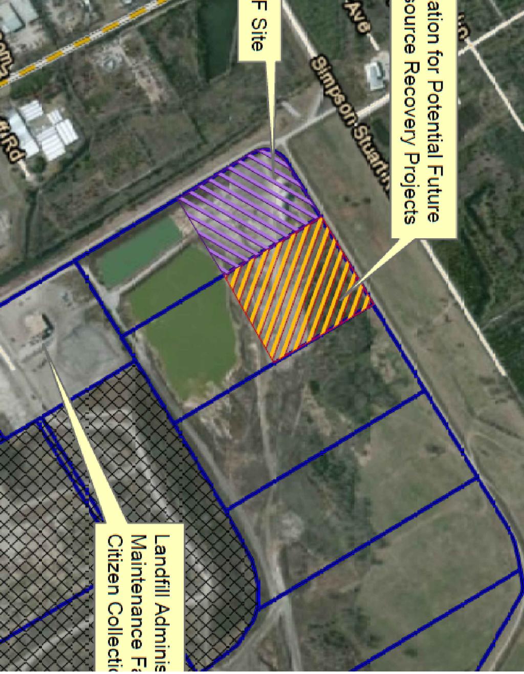
3 Report No G January 9, 2015 Page 1 INVESTIGATION AND ANALYSIS Introduction This report presents the results of a subsurface investigation performed for a new metal framed recycling facility at the McCommas Bluff Landfill site in Dallas, Texas. Recommendations for a ground supported floor-slab and floating floor slab are provided. Post-construction movements are to be limited to the order of 1-inch if a floating floor slab foundation is used. The purpose of this investigation has been to provide recommendations for evaluation, design, and construction of the foundation. This investigation has consisted of drilling and sampling, laboratory testing, engineering analysis, and preparation of this report. Recommendations are presented in the following sections. This report is specific to this site. Persons using the recommendations herein for projects and/or designs not covered by this report do so at their own risk. Field and Laboratory Investigation Subsurface conditions were evaluated with ten soil borings. Locations of the borings were dictated by site accessibility and are presented on Plate 1. Borings were drilled using a truckmounted rig equipped with continuous flight augers and extended to depths of 20 to 30 feet below existing (November & December 2014) grades. Relatively undisturbed samples of cohesive soil were obtained with three-inch diameter Shelby tubes. Fine grained sands was sampled and evaluated using Standard Penetration Test (SPT). Unweathered limestone was evaluated using the TxDOT Cone Penetration Test (CPT). Drilling and sampling were done in general accordance with ASTM methods and standards. All samples were transported to our laboratory for visual classification and testing. Soils were visually classified according to the Unified Soil Classification System (USCS). Rock materials were described using standard geological nomenclature. Boring Logs and a key to terms and symbols used on the logs are attached. Selected samples were tested to evaluate engineering properties, soil movement, and confirm visual classification. Tests conducted included Atterberg Limits (ASTM D-4318), moisture content determinations (ASTM D-2216) and partial gradation (percent passing No. 200 Sieve). Absorption Pressure-Swell tests were conducted to evaluate the potential for soil related heave. The strengths of selected samples were investigated by Unconfined Compression test. Results of the laboratory tests are presented on Plates 2 through 4.
4 Report No G January 9, 2015 Page 2 Surface and Subsurface Conditions At the time of the field investigation the property was open and undeveloped. Within the depths drilled, subsurface conditions consisted of fill and alluvial (i.e. transported) clay, sandy clay to clayey sand and fine grained sands over unweathered limestone associated with the Upper Cretaceous Austin Chalk. At the surface of Boring Nos. 1, 2, 3 and 4, clay and sandy clay fill was encountered. The fill was gray, dark brown to brown and light brown in appearance, moderately plastic (CL), contained varying amounts of limestone, sub-rounded gravel and brick fragments and extended to depths of 1 to 12 feet below current grades. Alluvial clay, sandy clay to clayey sand and fine grained sands were encountered at the surface of Boring Nos. 5 through 10 and below the fill material in Boring Nos. 1 through 4. The clay to sandy clay soils were dark brown, brown to light brown and dark grayish-brown in appearance, moderately plastic, and contained varying amounts of limestone fragments. The clayey sand to fine grained sands were light brown, gray to dark grayish-brown and brown in appearance, ranged from loose (relative density) to dense and contained varying amounts of sub-rounded and coarse gravel. Boring No. 4 terminated within the alluvial soil at a depth of 30 feet. Unweathered limestone was located in the rest of the borings at depths of 15 to 28 feet. The unweathered limestone was hard (rock hardness classification), gray in appearance and continued through the termination depths of 20 to 30 feet in these borings. Based on soil moisture and pocket penetrometer values, the soil profiles were relatively dry at the time of the field investigation. Ground water was present in all borings at depths ranging from 6 to 27-1/2 feet during drilling and post-drilling water level observations. The presence and depth to ground water will change with seasonal rainfall. Potential Vertical Movements Considering the combination of both cohesive and granular soils, movements at this site will be manifested as both settlement and heave over the life of the structure. Based on the results of the Standard Penetration Test and Absorption Pressure-Swell tests, the total amount of differential soil-related movement is anticipated to be on the order of 1-inch.
5 Report No G January 9, 2015 Page 3 DESIGN AND CONSTRUCTION RECOMMENDATIONS Introduction It is anticipated that foundation loads may be supported on a ground-supported stiffened slab or with a floating floor slab foundation. Considering the movements of 1-inch, remediation is not required for a floating floor slab coupled with a perimeter pier and beam system. Recommendations for both types of designs are presented in the following paragraphs. Foundation Recommendations The foundation may consist of a perimeter, pier supported grade beam with interior column loads supporting on individual piers; or a ground-supported stiffened slab. Recommendations for both types of design are presented in the following paragraphs. It should be noted that some differential movement of the foundation should be expected for either option. If no soil-related movement is acceptable, a pier-and-beam design with a suspended floor should be used. Recommendations for this type of design can be provided upon request. Floating Floor Slab Recommendations For a floating floor design, it is recommended that the interior slab should not be structurally connected to the perimeter grade beam. The perimeter grade beam may be founded on straightshaft piers that penetrate a minimum 12 feet below existing grades into the sandy clay and fine grained sands or penetrate a minimum of 1-foot into the gray unweathered limestone which was encountered in all borings with the exception of Boring No. 4. Piers founded in the sandy clay and fine grained sands should be designed for an allowable end bearing of 4 ksf, and skin friction of 0.9-ksf. Both of these values may be used considering a Factor of Safety of 3 against a shear or plunging failure. The piers also may be designed against uplift using a negative skin friction of 0.7 ksf. The skin friction values should only be applied to that portion of the pier shaft below the minimum penetration depth of 12 feet. Piers founded in the gray unweathered limestone should be designed for an allowable end bearing of 40 ksf, and skin friction of 5 ksf. Both of these values may be used considering a Factor of Safety of 3 against a shear or plunging failure. The piers may be designed against uplift using a negative skin friction of 3.5 ksf. These skin friction values should only be applied to that portion of the pier shaft below the minimum penetration of 1-foot into the gray limestone. Piers will also be subjected to uplift forces associated with heaving of the subsurface soils. These forces will be approximately 0.6-ksf acting over the upper 5 feet of the pier shaft surface area. Resistance to uplift will be a function of the dead weight of the concrete in the pier, foundation loads, and negative skin friction. Temperature reinforcing should be adequate to resist uplift forces associated with heaving of the surrounding clay soil. A minimum of one No. 5 vertical bar should be used.
6 Report No G January 9, 2015 Page 4 The weight of the concrete may be neglected when determining foundation loads. Settlements of approximately ½-inch should be anticipated with a pier foundation. Pier shaft excavations should be clean of all debris and dry prior to placement of concrete. To minimize the sloughing of granular soils and ground water into pier excavations, it is recommended that temporary casing be used. Excess concrete at the top of the pier shaft should be removed prior to placement of the exterior grade beam. This is to reduce the potential for soils to swell against the foundation. Construction Procedures Each pier installation should be vertical (within acceptable tolerances), placed in proper plan location and cleaned prior to concrete placement. Reinforcing steel cages should be prefabricated in a rigid manner to allow expedient placement of both steel and concrete into the excavation. It is essential that excavation of piers and the placement of both steel and concrete be completed in a continuous operation. In all cases, no portion of the stratum being counted on to provide structural support should be exposed to atmospheric conditions for more than eight hours following the completion of excavation prior to the placement of concrete. In order to confirm compliance with specifications and acceptability of the bearing stratum and pier excavation, a qualified and experienced geotechnical observer from this office should be present at all times during foundation installation. A minimum 6-inch void should be established and maintained below any pier-supported grade beams or pier caps to allow for heave of the subsurface soils. Retainer boards should be provided along the exterior of the grade beams to prevent soils from infiltrating into the void space over the life of the structures. Ground-Supported Foundation Recommendations Current literature indicates 4 to 4-1/2 inches is the maximum amount of movement a ground supported, stiffened slab can withstand. Considering PVM on the order of 1-inch, a ground supported, stiffened slab may be used if some post-construction movement is acceptable. If no movement can be tolerated, a suspended floor coupled with a pier and beam foundation should be used. Recommendations for this type of design can be provided upon request. A ground-supported foundation may be either conventionally reinforced or post-tensioned. A conventionally reinforced foundation may be designed using the Wire Reinforcement Institute (WRI) and/or the Building Research and Advisory Board (BRAB) 1 method. For this site, an 1 Building Research Advisory Board, Report 33 to the Federal Housing Administration Criteria for Selection and Design of Residential Slab-on-Ground, Publication 1571 National Academy of Sciences, Washington, D.C., 1968.
7 Report No G January 9, 2015 Page 5 Average Weighted Plasticity Index (PI w) of 23 was used. Considering slopes of less than 5% and using an unconfined compressive strength (Q u) of 2 kips per square foot (ksf), a Slope Correction Factor (C S) of 1.0 and an Over-consolidation Correction Factor (C O) of 0.85 should be used with the WRI Method. This results in an Effective PI of 20. A Climatic Rating (C W) of 20 is considered appropriate for this site. Based on the above values, a Support Index (C) of 0.93 is applicable for the BRAB Method, and a value of 0.05 (1-C) should be used for a WRI design. With the WRI method, a cantilevered length (l c) of 2.3 feet was derived using the previous information. It is recommended the l c be increased by a factor of 1.5 with a minimum length of 6 feet used for analysis purposes 2 Design of post-tensioned slabs is based on the Edge Moisture Variation Distance (e m), and the anticipated Differential Movements (y m) that can occur over this distance e m. The e m is based on the amount of anticipated annual rainfall and is derived from the Thornthwaite Index (TI). This index is measured in inches and indicates the amount of rainfall above or below the amount needed to support plant growth. It has been found that irrigation and landscaping can increase the TI by several inches. For this project a modified TI of +10 was used. Differential movements (y m) for design of slabs can be determined according to the Post- Tensioning Institute (PTI) 3. Differential movements for center lift and edge lift conditions are based on type of clay minerals, velocity of moisture flow through the subgrade, and depth to constant soil suction. If the adverse effects of vegetation, site drainage, and slope have been corrected, differential movements may be calculated using the method presented in the PTI manual. Based on experience in the North Texas area, differential movements for slabs on-ground can approach the total potential movement estimated from laboratory test results. The e m and y m values presented in Table 1 were derived using the PTI method. These values were modified considering the effect of irrigation on the TI and the results of the PVM analysis. Values in Table 1 may be used for dry subsurface conditions. 2 Recommended Practice for the Design of Residential Foundations, Version 1, Texas Section of the American Society of Civil Engineers (2002), p Design and Construction of Post-Tensioned Slabs-on-Ground, 3rd Edition, Post-Tensioning Institute, Phoenix, AZ (2008).
8 Report No G January 9, 2015 Page 6 Table 1 PTI DESIGN VALUES (PVM = 1-inch) Recycling Facility McCommas Bluff Landfill- Dallas, Texas Lift Condition Edge Moisture Variation Distance e m (ft.) Differential Movement y m (in.) Center Lift Edge Lift Grade beams should penetrate a minimum of 12 inches below finished grade and rest on undisturbed soil or compacted and tested fill. Beams may be sized using an allowable net bearing pressure of 3 ksf. This allowable bearing value contains a Factor of Safety of 3 considering a shear failure. The foundation should be designed to conform to the stiffness criteria presented in Table 6.2 of the current PTI Manual for different types of construction. Construction Considerations Expansion joints should be installed at locations selected by the architect to allow for deflection of interior walls. All loose soils, debris, and water should be removed from grade beam and pier excavations prior to placing concrete. The width and depth of grade beams should not vary across the length of the beam. A vapor barrier should be installed below the slab. All penetrations and joints should be sealed to lower the potential for migration of moisture through the floor. Plastic sheeting used for vapor retarders below the slabs should be draped or cut in such a way as to allow concrete to be placed directly against the sidewalls of the grade beam excavations. Sand and gravel should not be used to bed utility lines. Utility excavations should be backfilled using on-site soils placed under controlled conditions as outlined in the Earthwork Recommendations section. As a minimum, a four-foot long clay plug should be installed below the exterior grade beam where utility lines transition below the foundation. This clay plug should be installed as outlined in the Earthwork Recommendations section. If possible, all utility trenches should be sloped to drain away from the foundation.
9 Report No G January 9, 2015 Page 7 Positive drainage away from the foundation should be established during construction and maintained throughout the life of the structure. Landscaping beds should be designed and maintained to prevent water from ponding next to the foundation. Ponded water will increase subsurface moisture and consequently increase the potential for heave. Irrigation lines or heads should not be placed directly next to the foundation. It is recommended that all irrigation lines be kept a minimum of five feet from the edge of the residence. If possible, trees should not be planted directly next to the structure. Over time, vegetation will desiccate the clays, resulting in shrinkage of the subgrade. This shrinkage will be manifested as settlement of ground supported foundations. All trees should be planted a minimum of 1-1/2 times the mature height of the tree from the foundation. If trees will be planted next to the structure, consideration should be given to installing a vertical root barrier between the tree and the foundation. As a minimum the barrier should consist of a four-inch wide lean concrete wall extending to a depth of 6 feet from finished grades. An alternative is to use a minimum 6-mil thick plastic sheet draped within the excavation and backfilled using sand or gravel. Alternately, a root-barrier system similar to that produced by DeepRoot may be installed around the perimeter of the foundation. Vegetation should be planted outside of the root barrier, away from the foundation. Any trees to be cleared from or within ten feet of the building pad should have the root systems removed and the excavations filled with on-site soils placed under controlled conditions. Soils should be placed as presented in the Earthwork Recommendations section. Paving Recommendations Asphalt Pavement: Flexible asphalt pavement may be used for parking and drives. The upper six inches of subgrade below asphalt pavement should be stabilized using approximately 6% hydrated lime (27 pounds per square yard) to achieve a treated soil with a Plasticity Index of 15 or less. It is recommended that site specific testing of the subgrade be performed to evaluate the actual amount of lime required to provide a stabilized subgrade. Lime should be placed in general accordance with Item LIME TREATMENT the North Central Texas Council of Government (NCTCOG) Standard Specifications for Public Works Construction published in Lime treated soils should be compacted to a minimum of 95% of the maximum dry unit weight (ASMM D-698) with moisture contents at or above optimum. For light truck and car traffic the following section is recommended: 1 Type D Asphalt Surface Course over,
10 Report No G January 9, 2015 Page 8 2 Type A or B Coarse Graded Base Course. For heavy truck traffic the following section is recommended: 2 Type D Asphalt Surface Course over, 4 Type A or B Coarse Graded Base Course. All asphalt should be placed in accordance with Item 302 of the NCTCOG standard. Compaction tests and air void verification should be conducted to evaluate the in-place density of the asphalt pavement. All joints within asphalt pavements should be sealed and maintained to limit water infiltration into the subgrade soils. Concrete Pavement: Sections for reinforced concrete paving were evaluated using the Interim AASHO and PCA methods 4. Considering light vehicular traffic and less than six, fully loaded trucks per day, the following sections are recommended for a 20-year life span. For light truck and car traffic the following section is recommended: 5 of 3,000 psi Portland Cement Concrete over, 6 of recompacted subgrade. For heavy truck traffic up to 6 vehicles per day the following section is recommended: 6 of 3,000 psi Portland Cement Concrete over, 6 of recompacted subgrade. Routes for trash trucks should have the following: 7 of 3,000 psi Portland Cement Concrete over, 6 of recompacted subgrade. Subgrade soils below concrete pavements should be compacted to a minimum of 95% (ASTM D- 698) with moisture contents between 0 and +4 percentage points. Concrete pavement should be reinforced with No. 3 deformed bars on 18-inch centers. No. 4 smooth dowels should be used at expansion and construction joints on 12-inch centers. 4 Yoder, E.J., and Witczak, M.W., Principles of Pavement Design, 2 nd Ed., John Wiley & Sons, Inc., New York, NY, pp 605 to 608.
11 Report No G January 9, 2015 Page 9 Control joints should be installed in the pavement within four hours after concrete has been placed, not after completion of the pour. Joint spacing and depth should conform to the recommendations presented in the latest version of Joint Design for Concrete Highways and Street Pavements, produced by PCA. Spacing between control joints should not exceed 15-feet. All joints should be sealed and periodically maintained. This will limit the potential for water to infiltrate into the subgrade. Expansion joints should consist of doweled keyways, thickened sections, or steel dowels supported on a non-deteriorating medium such as bituminous mastic or bituminous impregnated cellulous 5. All expansion joints should be filled completely with sealant to the pavement surface. It should be noted that all fill below pavements to be placed within the City of Dallas right-of-way must be compacted to a minimum of 98% of the maximum dry unit weight as determined by ASTM D-698. A moisture content of at least +1 percentage point above optimum is recommended. Sidewalk subgrade within the City of Dallas right-of-way must be compacted to a minimum of 95% of the maximum dry unit weight as determined by ASTM D-698. A moisture content of at least +1 percentage point above optimum is recommended. Furthermore, lime stabilization of approach subgrade within the City of Dallas right-of-way will be required regardless of the type of pavement section used. Lime stabilization should be conducted in general accordance with Item LIME TREATMENT the North Central Texas Council of Government (NCTCOG) Standard Specifications for Public Works Construction published in Lime treated soils below city paving should be compacted to a minimum of 98% of the maximum dry unit weight (ASTM D-698). A moisture content of 0 to +4 percentage points above optimum is recommended. Earthwork Recommendations Prior to construction all areas to receive improvements should be stripped of organic materials. On-site soils should be placed in maximum 8-inch loose lifts and compacted to a minimum of 95% and a maximum of 98% of the maximum dry unit weight as determined by ASTM D-698. Moisture content should be between 0 and +4 percentage points above optimum. Fill around perimeter grade beams should be cleaned of all construction debris and sand, and placed in a controlled manner. Use of clean, compacted fill will lower the potential for water to migrate into the subgrade soils. Sand or gravel should not be used as backfill against perimeter beams. 5 Guide for Design and Construction of Concrete Parking Lots, ACI Committee 330, NRMCA Publication MSP 34, January 1988, p 330R-8.
12 Report No G January 9, 2015 Page 10 If the fill material encountered across this site has not been placed in a controlled manner it is recommended that the material be evaluated for in-place density and moisture content using a portable nuclear density gauge. The fill soils will need to be excavated in one-foot lifts and the exposed materials tested until natural, undisturbed soils are encountered. If excavation and compaction of this fill material is not an option then it is recommended that all foundations at this site be pier supported as outlined in the pier recommendations section of this report. Construction Inspection and Testing It is recommended that a representative of Henley-Johnston & Associates, Inc. be retained to monitor pier foundation construction on a full-time basis to ensure compliance with the recommendations of this report. Field density tests should be conducted on those areas that will receive fill. All fill should be tested at a rate of one test per lift for every 2,500 square feet of area, or fraction thereof. These field tests are to confirm proper compaction and moisture of fill materials. Backfill within utility trenches should receive density testing at a rate of one test per 8-inch lift for every 50 linear feet or fraction thereof.


13
14 GEOTECHNICAL INVESTIGATION REPORT NO G RECYCLING FACILITY McCOMMAS BLUFF LANDFILL DALLAS, TEXAS SUMMARY OF INDEX PROPERTIES BORING NUMBER DEPTH (ft.) LIQUID LIMIT (%) PLASTIC INDEX DUW (pcf) FINER #200 (%) MOISTURE CONTENT (%) UNIFIED SOIL CLASSIFICATION CL NONPLASTIC CL CL CL CL CL Plate 2
15 GEOTECHNICAL INVESTIGATION REPORT NO G RECYCLING FACILITY McCOMMAS BLUFF LANDFILL DALLAS, TEXAS SUMMARY OF INDEX PROPERTIES BORING NUMBER DEPTH (ft.) LIQUID LIMIT (%) PLASTIC INDEX DUW (pcf) FINER #200 (%) MOISTURE CONTENT (%) UNIFIED SOIL CLASSIFICATION NONPLASTIC NONPLASTIC CL NONPLASTIC CL NONPLASTIC CL SUMMARY OF ABSORPTION PRESSURE-SWELL TESTS BORING NUMBER DEPTH (ft.) SWELL PRESSURE (psf) GAIN IN MOISTURE (%) PERCENT SWELL (%) MATERIAL DESCRIPTION FILL: SANDY CLAY, light brown , FILL: SANDY CLAY, brown FILL: SANDY CLAY, dark brown , SANDY CLAY, light brown Plate 3
16 GEOTECHNICAL INVESTIGATION REPORT NO G RECYCLING FACILITY McCOMMAS BLUFF LANDFILL DALLAS, TEXAS SUMMARY OF UNCONFINED COMPRESSION TESTS - SOIL BORING NUMBER DEPTH (ft.) PEAK STRESS (psi) FAILURE STRAIN (%) MATERIAL DESCRIPTION FILL: SANDY CLAY, light brown FILL: SANDY CLAY, very stiff, dark brown SANDY CLAY, light brown Plate 4


17
18
19
20
21
22
23
24
25
26
27
28
29
30
31

32
33
34
GEOTECHNICAL INVESTIGATION. Proposed RETAIL DEVELOPEMNT 1300 W. Pflugerville Parkway Pflugerville, Texas PROJECT NO. 17-DG8780.
 GEOTECHNICAL INVESTIGATION PROJECT NO. 17-DG8780 Prepared for: PROFESSIONAL STRUCIVIL ENGINEERS, INC Austin, Texas Prepared by: GEOSCIENCE ENGINEERING & TESTING, INC. Dallas, Texas October, 2017 2712 Satsuma
GEOTECHNICAL ENGINEERING STUDY Urban Reserve Development White Rock Creek at DART Railway Dallas, Texas CTL Job No. DA6526
 GEOTECHNICAL ENGINEERING STUDY Urban Reserve Development White Rock Creek at DART Railway Dallas, Texas CTL Job No. DA6526 October 13, 2004 Urban Edge Developers Ltd P.O. Box 191166 Dallas, Texas 75219
GEOTECHNICAL INVESTIGATION. Proposed WONDERLAND MONTESSORI ACADEMY Legacy Drive Prosper, Texas PROJECT NO. 18-DG9174.
 GEOTECHNICAL INVESTIGATION Proposed WONDERLAND MONTESSORI ACADEMY PROJECT NO. 18-DG9174 Prepared for: Mr. SANJAY JOSHI Flower Mound, Texas Prepared by: GEOSCIENCE ENGINEERING & TESTING, INC. Dallas, Texas
TABLE OF CONTENTS 1.0 INTRODUCTION SCOPE OF WORK SUBSURFACE EXPLORATION Sampling Techniques Sample Disposal...
 TABLE OF CONTENTS Page No 1.0 INTRODUCTION... 1 2.0 SCOPE OF WORK... 1 3.0 SUBSURFACE EXPLORATION... 2 3.1 Sampling Techniques... 2 3.2 Sample Disposal... 2 4.0 LABORATORY TESTING... 3 5.0 SUBSURFACE STRATIGRAPHY...
SOIL AND FOUNDATION INVESTIGATION PROPOSED DUPLEX 3966 VRAIN STREET DENVER, COLORADO
 SOIL AND FOUNDATION INVESTIGATION PROPOSED DUPLEX 3966 VRAIN STREET DENVER, COLORADO Prepared for: G.J. GARDNER HOMES ATTN: DAVE PAGANO 7660 RALEIGH STREET WESTMINSTER, COLORADO 80030 PROJECT NO. 1090
PROJECT NO JUNE, 2016
 PROJECT NO. 21202 JUNE, 2016 GEOTECHNICAL INVESTIGATION NORTH CREEK APARTMENTS CARL STERN DRIVE AND F.M. 685 HUTTO, TEXAS Presented To: CMC COMMERCIAL REALTY GROUP, INC. DALLAS, TEXAS TABLE OF CONTENTS
GEOTECHNICAL STUDY PROPOSED PRE-OWNED FACILITY TO AN EXISTING DEALERSHIP AT MASON ROAD AND KATY FREEWAY KATY, TEXAS PROJECT NO.
 GEOTECHNICAL STUDY PROPOSED PRE-OWNED FACILITY TO AN EXISTING DEALERSHIP AT MASON ROAD AND KATY FREEWAY KATY, TEXAS PROJECT NO. 15-290E TO CWA CONSTRUCTION, INC. WOODWAY, TEXAS BY SERVICING TEXAS, LOUISIANA,
SECTION SOILS REPORT
 SECTION 02300 SOILS REPORT 1. GENERAL: 1.1 All work included under this heading shall be subject to the General Conditions of the entire operation. This Contractor is required to refer especially thereto.
GEOTECHNICAL STUDY PROPOSED CONCRETE ROADWAY TIKI ISLAND COMMUNITY GALVESTON COUNTY, TEXAS PROJECT NO E
 GEOTECHNICAL STUDY PROPOSED CONCRETE ROADWAY TIKI ISLAND COMMUNITY GALVESTON COUNTY, TEXAS PROJECT NO. 15-945E TO VILLAGE OF TIKI ISLAND TIKI ISLAND, TEXAS BY SERVICING TEXAS, LOUISIANA, NEW MEXICO, OKLAHOMA
REPORT OF SUBSURFACE EXPLORATION AND GEOTECHNICAL ENGINEERING SERVICES STEPHENVILLE RETAIL HIGHWAY 377 NEAR WOLFE NURSERY ROAD STEPHENVILLE, TEXAS FOR
 REPORT OF SUBSURFACE EXPLORATION AND GEOTECHNICAL ENGINEERING SERVICES STEPHENVILLE RETAIL HIGHWAY 377 NEAR WOLFE NURSERY ROAD STEPHENVILLE, TEXAS FOR CROESUS STEPHENVILLE, L.P. OCTOBER 10, 2006 GEOTECHNICAL
Let s Make a Difference. Presented by: Samuel Tran, P.E.
 Let s Make a Difference Presented by: Samuel Tran, P.E. October 22, 2015 OVERVIEW o Importance of Geotechnical Engineering o Geotechnical Foundation Recommendations o Geotechnical Construction Specifications
Geotechnical Investigation Long Timber Brewing Building Highway 99 and Kelly Street Monroe, Oregon TABLE OF CONTENTS
 Highway 99 and Kelly Street TABLE OF CONTENTS PROJECT INFORMATION... 1 FIELD EXPLORATION... 1 SITE CONDITIONS... 2 Surface Conditions:... 2 Subsurface Conditions:... 2 FILL.... 2 Topsoil.... 2 Clay Alluvium....
GEOTECHNICAL INVESTIGATION PROPOSED OUTFALL LOCATION CITY OF MORGAN S POINT DRAINAGE HARRIS COUNTY, TEXAS REPORT NO
 GEOTECHNICAL INVESTIGATION PROPOSED OUTFALL LOCATION CITY OF MORGAN S POINT DRAINAGE HARRIS COUNTY, TEXAS REPORT NO. 1140198001 Reported to: SIRRUS ENGINEERS, INC. Houston, Texas Submitted by: GEOTEST
mtec REPORT OF GEOTECHNICAL EXPLORATION FTFA Construct Bin Wall at HERD Eglin AFB, Florida
 mtec REPORT OF GEOTECHNICAL EXPLORATION FTFA 14-3001 - Construct Bin Wall at HERD Eglin AFB, Florida MTEC Project Number 2014-101 November 10, 2014 Revised: January 5, 2015 Prepared For: Peterson Engineering,
Lantz-Boggio Architects, P.C LBA Project No
 SECTION 313430- PART 1 GENERAL 1.1 WORK INCLUDED A. Provide all equipment, material, labor and supervision to design and install Engineered Aggregate Piers for the soil reinforcement. Design shall rely
SECTION / ENGINEERED AGGREGATE PIERS (SOIL REINFORCEMENT AND FOUNDATION SYSTEM)
") PART 1 GENERAL 1.01 WORK INCLUDED SECTION 02360 / 31 34 30.13 ENGINEERED AGGREGATE PIERS (SOIL REINFORCEMENT AND FOUNDATION SYSTEM) A. Provide all equipment, material, labor and supervision to design and
PART 1 GENERAL 1.01 WORK INCLUDED SECTION 02360 / 31 34 30.13 ENGINEERED AGGREGATE PIERS (SOIL REINFORCEMENT AND FOUNDATION SYSTEM) A. Provide all equipment, material, labor and supervision to design and
SLAB ON GRADE Insul-Joint or Expansion Joint Material as Required by A/E Specifications AquaCheck Liquid Coating 400 (Waterproofing Membrane) with Aqu
 with Aqu") INSTALLATION INSTRUCTIONS Note: The following installation instructions are based off of ASTM E 1643 (Standard Practice for Installation of Water Vapor Retarders Used in Contact with Earth or Granular
INSTALLATION INSTRUCTIONS Note: The following installation instructions are based off of ASTM E 1643 (Standard Practice for Installation of Water Vapor Retarders Used in Contact with Earth or Granular
SOIL DATA: Centennial Montessori. in McKinney, TX
 SOIL DATA: Centennial Montessori in McKinney, TX REPORT OF SUBSURFACE EXPLORATION AND GEOTECHNICAL ENGINEERING SERVICES CENTENNIAL MONTESSORI ACADEMY ELDORADO PARKWAY AT ALMA ROAD MCKINNEY, TEXAS FOR CENTENNIAL
EXECUTIVE SUMMARY. The soil conditions at the location of the proposed LaQuinta Inn and Suites on Medical
 EXECUTIVE SUMMARY The soil conditions at the location of the proposed LaQuinta Inn and Suites on Medical Drive in Pearsall, Texas were explored by drilling 5 borings to depths of 7 to 30 feet. Laboratory
Geotechnical Engineering Report
 The Residence at Yukon Hills Cornwell Drive and Vandament Avenue Yukon, Oklahoma May 20, 2016 Terracon Project No. 03165108 Prepared for: Jones Gillam Renz Architects, Inc. Salina, Kansas Prepared by:
May 2, Mr. Tim Kurmaskie, AIA ARCHITECT KURMASKIE ASSOCIATES, INC Washington Street Raleigh, NC
 Mr. Tim Kurmaskie, AIA ARCHITECT KURMASKIE ASSOCIATES, INC. 1030 Washington Street Raleigh, NC 27605-1258 May 2, 2017 Re: Report of Subsurface Investigation Westfield Rehabilitation & Health Care Additions
PROPOSED CONSTRUCTION
 February 19, 2014 Colorado State University Pueblo 2200 Bonforte Boulevard Pueblo, CO, 81003 Attention John Barnosky, Director Subject: Geotechnical Investigation Soccer/Lacrosse Field Modifications Colorado
SECTION XXXXX AGGREGATE PIERS PART 1 - GENERAL
 SECTION XXXXX AGGREGATE PIERS PART 1 - GENERAL 1.1 RELATED DOCUMENTS: Drawings and general provisions of the Contract, including General and Supplementary Conditions and other Division 00 and Division
April 7, Webster Street Sub-Surface Stormwater Storage System Bid No Bid Date: 4/13/17 ADDENDUM NO 1
 PUBLIC WORKS DEPARTMENT David A. Jones, P.E., Director April 7, 2017 Webster Street Sub-Surface Stormwater Storage System Bid No. 2017-022 Bid Date: 4/13/17 ADDENDUM NO 1 Please make the following changes
PRELIMINARY GEOTECHNICAL INVESTIGATION UCCS ACADEMIC OFFICE BUILDING COLORADO SPRINGS, COLORADO
 PRELIMINARY GEOTECHNICAL INVESTIGATION UCCS COLORADO SPRINGS COLORADO Prepared for: UNIVERSITY OF COLORADO AT COLORADO SPRINGS Facilities Services 1420 Austin Bluffs Parkway Colorado Springs Colorado 80918
GEOTECHNICAL/GEOPHYSICAL INVESTIGATION
 GEOTECHNICAL/GEOPHYSICAL INVESTIGATION at PROPOSED GLASS RESIDENCE HOUSTON, TEXAS Prepared for Mr. Joe Glass 9215 Hilldale Houston, TX by BRYANT CONSULTANTS, INC. GEOTECHNICAL AND FORENSIC ENGINEERING
Northern Colorado Geotech
 GEOTECHNICAL ENGINEERING REPORT PROPOSED RESIDENTIAL DEVELOPMENT MORGAN COUNTY ROADS AND P WIGGINS, COLORADO NORTHERN COLORADO GEOTECH PROJECT NO. 07- JANUARY 9, 06 Prepared for: Town of Wiggins 0 Central
Geotechnical Engineering Study
 Geotechnical Engineering Study SAWS Regional Carrizo Water Integration Pump Station Project Schertz and San Antonio, Texas Arias Job No. 2010-895 Prepared For Tetra Tech, Inc. November 30, 2011 ARIAS &
Subsurface Exploration and Geotechnical Evaluation Hotel at Burnet Road (MoPac) Austin, Texas. Prepared for: Visvanath, LP 3120 Montopolis Drive
 Austin, Texas. Prepared for: Visvanath, LP 3120 Montopolis Drive") Nicholas F. Kauffman, M.S., P.E. Principal Geotechnical Engineer Subsurface Exploration and Geotechnical Evaluation Hotel at 13311 Burnet Road (MoPac) Austin, Texas Prepared for: Visvanath, LP 3120 Montopolis
Nicholas F. Kauffman, M.S., P.E. Principal Geotechnical Engineer Subsurface Exploration and Geotechnical Evaluation Hotel at 13311 Burnet Road (MoPac) Austin, Texas Prepared for: Visvanath, LP 3120 Montopolis
PROJECT INFORMATION. 1.1 Site Location. October 4, Jerry Schwab/President 315 Aden Ave., Suite 26 Glendale, CA 91203
 October 4, 2017 Jerry Schwab/President 315 Aden Ave., Suite 26 Glendale, CA 91203 P: 888.900.3823 E: jscwab@schwabeng.com Re: Geotechnical Engineering Letter Report VAMC Bldg 202 Domiciliary C-D Entryway
The Addendum supersedes all previous Drawings, Specifications, Addendum and instructions pertaining to these items.
 ADDENDUM NO. TWO 30 August 2016 Dudycha Shell Office Buildings Park Hudson Bryan, Texas R.L. Payne & Associates, Inc. 1509 Emerald Parkway, Suite 104 College Station, Texas 77845 NOTICE TO ALL BIDDERS:
ST. TAMMANY PARISH COUNCIL ORDINANCE
 ST. TAMMANY PARISH COUNCIL ORDINANCE ORDINANCE CALENDAR NO: 5563 COUNCIL SPONSOR: DEAN/BRISTER INTRODUCED BY: MR. BELLISARIO ORDINANCE COUNCIL SERIES NO: PROVIDED BY: DEVELOPMENT SECONDED BY: MR. STEFANCIK
Civil Geotechnical Surveying
 Civil Geotechnical Surveying Mr. David Burnett Cabarrus County Schools 4425 Old Airport Road Charlotte, North Carolina 28025 May 16, 2017 Reference: Geotechnical Engineering Evaluation Future PLC Site
5.0 SITE CONDITIONS. 5.1 Surface Conditions
 5.0 SITE CONDITIONS 5.1 Surface Conditions The project site is located at approximately along Ashdown Forest Road and Nichols Canyon Road in the Fiddlers Canyon Area of Cedar City, Utah. At the time of
August 13, Geotechnical Recommendations, New Physical Education Building, Chabot College, Hayward, California
 August 13, 2008 003-09176-17 Douglas Horner, AIA Chabot Las Positas Community College District 25555 Hesperian Boulevard Hayward, California 94545 Subject: Geotechnical Recommendations, New Physical Education
Geotechnical Engineering Study Report
 Geotechnical Engineering Study Report The report has been prepared for use in developing an overall design concept. Paragraphs, statements, test results, boring logs, diagrams, etc., should not be taken
Applied GeoScience, Inc Hammond Dr., Suite 6 Schaumburg, Illinois
 AGI Project No. 13-276 Subsurface Investigation Report For the Proposed New Retail Center 9601 South Pulaski Road Evergreen Park, Illinois Prepared for Mr. Feras Sweis FHS Design + Build LLC 2010 West
GEOTECHNICAL ENGINEERING REPORT. Proposed Austin at Tech Ridge 1000 Feet South of Center Ridge Dr. and Mouse Ln. Austin, Texas
 GEOTECHNICAL ENGINEERING REPORT Proposed Austin at Tech Ridge 1000 Feet South of Center Ridge Dr. and Mouse Ln. Austin, Texas PSI Project No. 03011353 PREPARED FOR: RD Management, LLC. 810 Seventh Avenue,
Geotechnical Engineering Study
 Geotechnical Engineering Study Proposed Escondido Creek Parkway Kenedy, Texas Arias Job No. 2017-297 Prepared For Dunaway Associates November 28, 2017 , GEOPROFEIONALS 142 Chula Vista, San Antonio, Texas
Subsurface Investigation Report. Proposed New 1-Story Building 6447 Grand Avenue Gurnee, Illinois
 AGI Project No. -11 Subsurface Investigation Report For the Proposed New 1-Story Building 6447 Grand Avenue Gurnee, Illinois Prepared for Mr. Steve Panko Key Development Partners, LLC North State Street,
GEOTECHNICAL INVESTIGATION KIPP JOURNEY MODULAR CAMPUS KIPP WAY HOUSTON, TEXAS. Reported to KIPP Texas Public Schools Houston, Texas
 GEOTECHNICAL INVESTIGATION KIPP JOURNEY MODULAR CAMPUS 10711 KIPP WAY HOUSTON, TEXAS Reported to KIPP Texas Public Schools Houston, Texas by Aviles Engineering Corporation 5790 Windfern Houston, Texas
GEOTECHNICAL STUDY HIDDEN VALLEY SPORTS PARK RESTROOM FACILITY MABEL JONES DRIVE CANYON LAKE, TEXAS
 FUGRO CONSULTANTS, INC. GEOTECHNICAL STUDY HIDDEN VALLEY SPORTS PARK RESTROOM FACILITY MABEL JONES DRIVE CANYON LAKE, TEXAS COMAL COUNTY Canyon Lake, Texas GEOTECHNICAL STUDY HIDDEN VALLEY SPORTS PARK
GEOTECHNICAL EXPLORATION. TWO MEDICAL OFFICE BUILDINGS N. Beach Street and Heritage Glen Drive Fort Worth, Texas ALPHA Report No.
 GEOTECHNICAL EXPLORATION on TWO MEDICAL OFFICE BUILDINGS N. Beach Street and Heritage Glen Drive Fort Worth, Texas ALPHA Report No. G152751 Prepared for: CASTLE DEVELOPMENT GROUP P. O. Box 96255 Southlake,
SECTION TRENCHING
 SECTION 31 23 17 TRENCHING PART 1 GENERAL 1.1 SUMMARY A. Section Includes: 1. Excavating trenches for utilities and utility structures. 2. Bedding. 3. Backfilling and compacting to subgrade elevations.
Geotechnical Engineering Report
 Geotechnical Engineering Report Amara Apartments at the Rim Talavera Ridge and Old Camp Bullis Road San Antonio, Texas June 27, 2016 Terracon Project No. 90165068 Prepared for: Oden Hughes Austin, Texas
Geotechnical Engineering Report
 Proposed Metal Building Recycling Drop-Off Facility 590 Interstate Highway 45 North Huntsville, Texas December 28, 2010 Terracon Project No. 97105093 Prepared for: Jones & Carter, Inc. The Woodlands, Texas
SECTION XXXXX STONE COLUMNS PART 1 - GENERAL
 SECTION XXXXX STONE COLUMNS PART 1 - GENERAL 1.1 RELATED DOCUMENTS: Drawings and general provisions of the Contract, including General and Supplementary Conditions and other Division 00 and Division 01
Utility Cut Restoration
 Design Manual Chapter 9 - Utilities 9D - Utility Cut Restoration 9D-1 Utility Cut Restoration A. General Utility cuts are made in existing pavement sections to install a myriad of utilities and to repair
SECTION FILL AND BACKFILL
 PART 1 GENERAL 1.1 SECTION INCLUDES A. Filling, backfilling, and compacting for building volume below grade, footings, slabs-on-grade, paving, site structures, and utilities within the building. B. Backfilling
Minimum Guidelines for the Design and Use of Underpins When Performing Foundation Stabilization and/or Supplementation UP-08
 Minimum Guidelines for the Design and Use of Underpins When Performing Foundation Stabilization and/or Supplementation UP-08 Table of Contents 1. Title 2. Designation 3. List of Figures 4. Scope 5. Referenced
GEOTECHNICAL INVESTIGATION MDACC GUHN ROAD FLOOD MITIGATION PROJECT 5610 GUHN ROAD HOUSTON, TEXAS REPORT NO
 GEOTECHNICAL INVESTIGATION MDACC GUHN ROAD FLOOD MITIGATION PROJECT 5610 GUHN ROAD HOUSTON, TEXAS REPORT NO. 1140189301 Reported to: URS CORPORATION Houston, Texas Reported by: GEOTEST ENGINEERING, INC.
GEOTECHNICAL ENGINEERING STUDY. For
 GEOTECHNICAL ENGINEERING STUDY For PROPOSED RESIDENCE INN BY MARRIOTT ALONG THE SOUTH SIDE OF SPUR 54 JUST NORTH OF THE EXISTING BASS PRO SHOPS HARLINGEN, CAMERON COUNTY, TEXAS Prepared for KRISHNA HARLINGEN
ORLANDO SANFORD INTERNATIONAL AIRPORT OUTPARCEL 6 SANFORD, FLORIDA
 PRELIMINARY GEOTECHNICAL STUDY ORLANDO SANFORD INTERNATIONAL AIRPORT OUTPARCEL 6 SANFORD, FLORIDA November 9, 2015 Prepared For: Ms. Diane H. Crews, A.A.E. Sanford Airport Authority 1200 Red Cleveland
Geotechnical Engineering Report
 REPORT COVER PAGE Geotechnical Engineering Report Townwest Commons Hutto, Texas August 24, 2018 Terracon Project No. 96185224 Prepared for: NewQuest Properties Houston, Texas Prepared by: Terracon Consultants,
REPORT OF GEOTECHNICAL EXPLORATION GLYNN COUNTY DETENTION CENTER GLYNN COUNTY, GEORGIA E&A PROJECT NO
 REPORT OF GEOTECHNICAL EXPLORATION GLYNN COUNTY DETENTION CENTER GLYNN COUNTY, GEORGIA E&A PROJECT NO. - Prepared for: IPG Architects, Inc. Northwood Park Drive Valdosta, Georgia Prepared by: Ellis & Associates,
SECTION EARTHWORK
 SECTION 02200 EARTHWORK PART 1 - GENERAL 1.01 WORK INVOLVED A. Provide all labor, materials and equipment as required for all excavation, grading, providing borrow materials, hauling, placing and compacting
SUBSURFACE INVESTIGATION & GEOTECHNICAL RECOMMENDATIONS PROPOSED MONOPOLE CELL TOWER INDIANAPOLIS, INDIANA A&W PROJECT NO: 15IN0464
 SUBSURFACE INVESTIGATION & GEOTECHNICAL RECOMMENDATIONS PROPOSED MONOPOLE CELL TOWER INDIANAPOLIS, INDIANA A&W PROJECT NO: 15IN0464 PREPARED FOR: AAA DEVELOPMENT AND CONSULTING, INC GREENFIELD, INDIANA
B. Subsurface data is available from the Owner. Contractor is urged to carefully analyze the site conditions.
 SECTION 31 23 33 - TRENCHING, BACKFILLING AND COMPACTION PART 1 - GENERAL 1.1 SCOPE A. This Section specifies the requirements for excavating and backfilling for storm sewer, sanitary sewer, water distribution
Subsurface Exploration and Geotechnical Evaluation New Church for Bateman Baptist Church FM 20, Bastrop County, Texas.
 Nicholas F. Kauffman, M.S., P.E. Principal Geotechnical Engineer Mobile: (512)217-8423 Subsurface Exploration and Geotechnical Evaluation New Church for Bateman Baptist Church FM 20, Bastrop County, Texas
SUBSURFACE EXPLORATION, LABORATORY TESTING PROGRAM, AND FOUNDATION AND PAVEMENT RECOMMENDATIONS
 GEOTECHNICAL ENGINEERING CONSTRUCTION MATERIALS ENGINEERING & TESTING SOILS ASPHALT CONCRETE Elsasser Architectural Inc. P.O. Box 833 Georgetown, Texas 78627 Attention: Richard Elsasser relsasser@eai-tx.com
Subsurface Exploration and Foundation Analysis Proposed New Weight Room / Fieldhouse Building 429 N Highway 83 Leakey, Texas
 Subsurface Exploration and Foundation Analysis Proposed New Weight Room / Fieldhouse Building 429 N Highway 83 Leakey, Texas InTEC Project No. S161639 April 18, 2016 Leakey ISD P.O. Box 1129 Leakey, Texas
GEOTECHNICAL REPORT. Sunshine Adult Day Services Ardmore, Oklahoma. EIKON Project # September Prepared by
 GEOTECHNICAL REPORT Sunshine Adult Day Services Ardmore, Oklahoma EIKON Project #14167 September 2014 Prepared by September 30, 2014 Ms. Melissa Walker Sunshine Industries, Inc. Box 1729 Ardmore, Oklahoma
GEOTECHNICAL ENGINEERING STUDY. Brodie Marketplace Brodie Lane & Deer Lane Austin, Texas
 GEOTECHNICAL ENGINEERING STUDY Brodie Marketplace Brodie Lane & Deer Lane Austin, Texas PSI Project No. 0303857 PREPARED FOR: Investcor, LLC 360 Nueces Street, Suite 40 Austin, Texas 78701 March 21, 2016
Investigation of Foundation Failure of a Residential Building A Case Study
 D. Nagarajan et al Int. Journal of Engineering Research and Applications RESEARCH ARTICLE OPEN ACCESS Investigation of Foundation Failure of a Residential Building A Case Study D. Nagarajan*, K. Premalatha**
SECTION RIGID PAVEMENT
 SECTION 02750 PART 1 GENERAL RIGID PAVEMENT 1.1 SUMMARY A. Section Includes: 1. Concrete sidewalks. 2. Concrete stair steps. 3. Concrete integral curbs gutters. 4. Concrete parking areas and roads. B.
April 21, Odom Investments, Inc. Attn: Mr. Jerry Odom 7100 Westwind Dr., Suite 230 El Paso, TX 79912
 April 21, 2016 Odom Investments, Inc. Attn: Mr. Jerry Odom 7100 Westwind Dr., Suite 230 El Paso, TX 79912 Re: GEOTECHNICAL ENGINEERING REPORT Proposed San Elizario Retail Center Socorro Road & Chicken
B. The Bidder shall acknowledge receipt of this Addendum in the appropriate space on the Bid Form.
 City of Casper Baler Building / MRF Expansion DOCUMENT 9113 ADDENDUM.1 ADDENDUM NUMBER: 1.2 PROJECT INFORMATION A. Project Name: Baler Building / MRF Expansion B. Owner: City of Casper C. Architect: Hein
Geotechnical Engineering Report
 Geotechnical Engineering Report Parking Lot Evaluation & Physical Plant Additions Rogers State University Claremore, Oklahoma May 20, 2015 Terracon Project No. 04155080 Prepared for: Rogers State University
GEOTECHNICAL EXPLORATION. HESTER PROPERTY E. Rocky Creek Road Fort Worth, Texas ALPHA Report No. W152959
 GEOTECHNICAL EXPLORATION on HESTER PROPERTY 11103 E. Rocky Creek Road Fort Worth, Texas Geotechnical Construction Materials Environmental GEOTECHNICAL EXPLORATION on HESTER PROPERTY 11103 E. Rocky Creek
Geotechnical Engineering Evaluation Campbell County Athletic Play Fields Campbell County High School South Campus Gillette, Wyoming
 March 9, 2016 Proposal No. WYP16064 Campbell County School District Mr. Andy Mravlja 1000 W. 8 th Street Gillette, WY 82716 amravlja@ccsd.k12.wy.us RE: PROPOSAL Geotechnical Engineering Evaluation Campbell
GEOTECHNICAL ENGINEERING REPORT PROPOSED HOLIDAY INN HOTEL BENTLEY CIRCLE AND EAST 2ND STREET CASPER, WYOMING
 GEOTECHNICAL ENGINEERING REPORT PROPOSED HOLIDAY INN HOTEL BENTLEY CIRCLE AND EAST 2ND STREET CASPER, WYOMING TERRACON PROJECT NO. A07002 February 19, 2007 Prepared for: Sweetwater Interest, LLC P.O. Box
Geotechnical Engineering Report
 Stone Hill Town Center Tract 12B Limestone Commercial Drive Pflugerville, Texas December 18, 2017 Terracon Project No. 96175391 Prepared for: NewQuest Properties Houston, Texas Prepared by: Terracon Consultants,
Geotechnical Investigation for Navajo Gallup Water Supply Project Reach 26.3
 Geotechnical Investigation for Navajo Gallup Water Supply Project Reach 26.3 Geo-Test Geotechnical Engineering Services Report No. 1-718 for Reach 26.3 Tank Site Geo-Test Job No. 1-718, Addendum No. 1
GEOTECHNICAL SUBSURFACE INVESTIGATION RECOMMENDATIONS FOR THE TAMUCC MOMENTUM FIELD LIGHT POLES NILE DRIVE CORPUS CHRISTI, TEXAS
 GEOTECHNICAL ENGINEERING MATERIALS ENGINEERING & TESTING SOILS ASPHALT CONCRETE GEOTECHNICAL SUBSURFACE INVESTIGATION RECOMMENDATIONS FOR THE NILE DRIVE CORPUS CHRISTI, TEXAS RETL REPORT NUMBER: G118442
GEOTECHNICAL ENGINEERING REPORT
 GEOTECHNICAL ENGINEERING REPORT PROJECT MINECRAFT ACCESS ROAD BOYDTON PLANK ROAD DINWIDDIE COUNTY, VIRGINIA JOB NUMBER: 37775.003 PREPARED FOR: DINWIDDIE COUNTY PO BOX 70 DINWIDDIE COUNTY, STATE 23841
SUBSURFACE SOIL INVESTIGATION
 Architecture Forensic Civil/Planning SUBSURFACE SOIL INVESTIGATION The Overlook Subdivision Phase 3 S1/2 Sec. 2 & SE 1/4 Sec. 3, T6N, R67W of the 6th P.M. Severance, Colorado PREPARED FOR: Journey Homes,
Mr. Cliff Bates, VP of Development The Park Companies 124 One Madison Plaza, Suite 1500 Madison, Mississippi Report No.
 January 29, 19 Mr. Cliff Bates, VP of Development The Park Companies 124 One Madison Plaza, Suite 0 Madison, Mississippi 391 Report No.180667 Geotechnical Exploration The Park at Barton Residential Community
March 12, Vasu Demla, LLC 3525 Sandy Trail Lane Plano, TX Attention: Mr. Suraj Sunny Demla
 March 12, 2012 Vasu Demla, LLC 3525 Sandy Trail Lane Plano, TX 75023 Attention: Mr. Suraj Sunny Demla Re: Report of Subsurface Exploration and Geotechnical Study for the Proposed Home2 Suites Development
Geotechnical Engineering Report
 Geotechnical Engineering Report Anderson County Hospital 421 S. Maple Street Garnett, KS December 14, 2012 Terracon Project No. 021221 Prepared for: Saint Luke s Health System, Inc. Kansas City, MO Prepared
SECTION MECHANICALLY STABILIZED EARTH RETAINING WALLS
 SECTION 13100 MECHANICALLY STABILIZED EARTH RETAINING WALLS PART 1 -- GENERAL 1.01 THE REQUIREMENT A. Includes all labor, material, equipment, testing and submittals required to design and complete construction
GEOTECHNICAL EXPLORATION. DENTAL DEPOT 5014 Main Street The Colony, Texas ALPHA Report No. G Prepared for:
 GEOTECHNICAL EXPLORATION on DENTAL DEPOT 5014 Main Street The Colony, Texas ALPHA Report No. G151847 Prepared for: FITZGERALD & ASSOCIATES 3900 N. Santa Fe Avenue Oklahoma City, Oklahoma 73118 Attention:
Geotechnical Engineering Report
 Geotechnical Engineering Report Sterling Site Office Building Commerce Street San Antonio, Texas Prepared for: Jasmine Engineering San Antonio, Texas Prepared by: TTL/Drash Consultants, LLC San Antonio,
.1 Furnish all labor, material and equipment necessary to complete all Site Work as shown on the Drawings and Specifications.
 SECTION 31 22 00- GRADING 1.0 GENERAL.1 Furnish all labor, material and equipment necessary to complete all Site Work as shown on the Drawings and Specifications.. 2 Excavate to exact line and grade as
SUBSURFACE INVESTIGATION, LABORATORY TESTING PROGRAM, AND PAVEMENT RECOMMENDATIONS
 February 7, 2017 EDR Architects, PLLC PO Box 271613 Corpus Christi, TX 78427 Attention: Ms. Emily D. Rozypal, AIA SUBJECT: SUBSURFACE INVESTIGATION, LABORATORY TESTING PROGRAM, AND PAVEMENT RECOMMENDATIONS
Geotechnical Investigation
 REVISED Geotechnical Investigation Pueblo Pintado Tank Site Includes NGWSP Reaches 26.1 & 26.2 Pueblo Pintado in New Mexico Prepared for: Souder, Miller & Associates Project No.: 15-1-057 June 9, 2016
GEOTECHNICAL INVESTIGATION
 GEOTECHNICAL INVESTIGATION Proposed Student Union Building Killeen, Texas Kleinfelder Project No. 95751 August 18, 2008 TABLE OF CONTENTS IMPORTANT INFORMATION ABOUT YOUR GEOTECHNICAL ENGINEERING REPORT...
Geotechnical Exploration and Evaluation Report
 Geotechnical Exploration and Evaluation Report Nassau Reclaimed Water Main From Radio Avenue to Harts Road Nassau County, Florida CSI Geo Project No.: 71-17-329-04 Client Project No.: JEA 09302-049-01
PROJECT INFORMATION...
 TABLE OF CONTENTS Page No. PROJECT INFORMATION... 1 PROJECT AUTHORIZATION... 1 PROJECT DESCRIPTION... 1 PURPOSE AND SCOPE OF SERVICES... 1 SITE AND SUBSURFACE CONDITIONS... 3 SITE LOCATION AND DESCRIPTION...
GEOTECHNICAL ENGINEERING STUDY
 GEOTECHNICAL ENGINEERING STUDY FOR CST CORNER STORE NO. 1858 LOOP 1604 AND NEW GUILBEAU ROAD SAN ANTONIO, TEXAS GEOTECHNICAL ENGINEERING STUDY For CST CORNER STORE NO. 1858 LOOP 1604 AND NEW GUILBEAU
DIVISION 4100 SITEWORK
 DIVISION 4100 SITEWORK SECTION 4115 EARTHWORK PART 1 - GENERAL 1.01 SCOPE This section covers the grading and compaction of excavations, embankments, structural foundations, and planted areas. 1.02 REFERENCES
GEOTECHNICAL ENGINEERING REPORT
 GEOTECHNICAL ENGINEERING REPORT Project: NW Bucklin Hill at Silverdale Way NW Project Number: 12023 Prepared for: Barber Development P.O. Box 473 Redmond, WA 98073 Prepared by: South Sound Geotechnical
GEOTEK ENGINEERING & TESTING SERVICES, INC. 909 East 50 th Street North Sioux Falls, South Dakota Phone Fax
 GEOTEK ENGINEERING & TESTING SERVICES, INC. 909 East 50 th Street North Sioux Falls, South Dakota 57104 Phone 605-335-5512 Fax 605-335-0773 May 10, 2016 Banner Associates, Inc. 2307 W. 57 th Street, Suite
Proposed Family Dollar Store Watford City, North Dakota. 7B Building & Development Lubbock, Texas January 26, Terracon Project No.
 Proposed Family Dollar Store Watford City, North Dakota Terracon Project No. M5165122 Prepared for: 7B Building & Development Lubbock, Texas January 26, 2017 January 26, 2017 7B Building & Development
Geotechnical Investigation Report
 Geotechnical Investigation Report Proposed,000-Gallon Water Storage Tank Fagasa Pass Tank Upper Pago Pago, American Samoa Prepared for: ASPA Water Engineering Division Tafuna, American Samoa PO Box PPB
In preparation for constructing buildings on a property, the builder. Site Preparation CHAPTER
 CHAPTER 3 Site Preparation In preparation for constructing buildings on a property, the builder must consider a number of factors related to code requirements. The buildings must be located according to
DEPARTMENT OF TRANSPORTATION DIVISION: MATERIALS REPORT COVER SHEET. Revised Soil Survey Report November 24, 2015 Matthew G. Moore, P.E.
 LD-0 /12/09 DEPARTMENT OF TRANSPORTATION DIVISION: MATERIALS REPORT COVER SHEET Revised Soil Survey Report November 2, 201 Matthew G. Moore, P.E. VDOT (Division) or Company Name Insert Location, Virginia
SPECIFICATIONS FOR PRECAST MODULAR BLOCK RETAINING WALL SYSTEM (revised 5/8/7)
") Page 1 of 7 STONE STRONG SYSTEMS SPECIFICATIONS FOR PRECAST MODULAR BLOCK RETAINING WALL SYSTEM (revised 5/8/7) PART 1: GENERAL 1.01 Description A. Work includes furnishing and installing precast modular
Page 1 of 7 STONE STRONG SYSTEMS SPECIFICATIONS FOR PRECAST MODULAR BLOCK RETAINING WALL SYSTEM (revised 5/8/7) PART 1: GENERAL 1.01 Description A. Work includes furnishing and installing precast modular
Woodhaven Retirement Community Addition Wentworth Street Livonia, Michigan 48154
 Report of Geotechnical Investigation Woodhaven Retirement Community Addition 9 Wentworth Street Livonia, Michigan 81 Latitude.08 N Longitude 8.898 W Prepared for: Fusco, Shaffer & Pappas, Inc. 0 E. Nine
B. Borrow: Satisfactory soil imported from off-site for use as fill or backfill.
 SECTION 312000- EARTHWORK PART 1 - GENERAL 1.1 RELATED DOCUMENTS Drawings and general provisions of the Contract, including General and Special Conditions, apply to this Section. 1.2 SUMMARY This Section
GEOTECHNICAL ENGINEERING REPORT
 GEOTECHNICAL ENGINEERING REPORT 58.6 ROAD (KIMBALL CREEK) 58.9 ROAD TO 58.7 ROAD MESA COUNTY, COLORADO February 9, 2018 Prepared By: Prepared For: Mr. Eric Krch, P.E. SGM, Inc. 744 Horizon Court, Suite