Design Illustrations on the Use of Soil Nails to Upgrade Loose Fill Slopes
|
|
|
- Theodore Hodges
- 6 years ago
- Views:
Transcription


1 Design Illustrations on the Use of Soil Nails to Upgrade Loose Fill Slopes Geotechnical Engineering Office and The Hong Kong Institution of Engineers (Geotechnical Division) November 2013
2 2 Disclaimer This report presents design examples with reference to the guidelines given in Geoguide 7: Guide to Soil Nail Design and Construction promulgated by the Geotechnical Engineering Office of the Civil Engineering and Development Department (GEO/CEDD), and new design recommendations suggested in the report entitled Design of Soil Nails for Upgrading Loose Fill Slopes jointly published by the GEO/CEDD and the Hong Kong Institution of Engineers, Geotechnical Division (GEO-HKIE, 2011). The Hong Kong Institution of Engineers and GEO/CEDD do not accept any responsibility for the use or misuse of this report. A designer using the recommendations contained in this report shall retain total responsibility for the adequacy of the design.
3 3 Abstract Based on the findings from a study initiated by the Geotechnical Engineering Office of the Civil Engineering and Development Department (GEO/CEDD), new design guidelines which supplement the original design guidance for the use of soil nails to upgrade loose fill slopes have been recommended and are summarised in a report jointly published by the GEO/CEDD, and The Hong Kong Institution of Engineers, Geotechnical Division (GEO-HKIE, 2011). The new guidelines recommend the use of a hybrid nail arrangement comprising soil nails at two different orientations. A design procedure for delineating loose fill at great depths which can be assumed to be non-liquefiable is also recommended. To demonstrate the implementation of the new recommendations given in the GEO-HKIE (2011) Report, GEO-HKIE prepared three worked examples pursuant to the new recommendations, which are presented in this report. The first example demonstrates the procedure for adopting the hybrid nail arrangement, which is a novelty to local practitioners. The second example assumes that steeply inclined nails have to be adopted due to site constraints. The design therefore includes the provision of an embedded concrete footing which aims to reduce slope deformation. The effectiveness of the nail arrangement is verified by numerical analysis. The last example considers a fill slope with loose fill of a considerable depth, and illustrates the procedure to delineate the non-liquefiable loose fill zone by limit equilibrium method. Recommendations in respect of the selection of design parameters are also presented in the worked examples. The draft version of this report was issued in April 2013, and circulated for comments among government departments and practitioners via The Hong Kong Institution of Engineers, Geotechnical Division (HKIE-GD). These comments and the responses are attached in Appendix B. The salient points of these comments and responses are summarised in Section 5. The worked examples serve to illustrate the principles of the design guidelines only, and the design parameters, assumptions and considerations adopted in the worked examples are not meant to be adopted for general design purposes. Designers should use design parameters appropriate to their project at hand.
4 4 Contents Title Page 1 Disclaimer 2 Abstract 3 Contents 4 List of Tables 6 List of Figures 7 1 Introduction 1.1 Background General Design Procedure 10 Page No. 2 Worked Example 1 Design for Hybrid Nail Arrangement 2.1 Design Scenario and Assumptions Stability Assessment of the Loose Fill Slope without Soil Nails Determination of Earth Pressure to be Sustained by Soil Nails Design of Soil Nails Stability Assessment of the Loose Fill Slope with Soil Nails 17 under Drained Conditions 2.6 Design of Grillage Structure and Soil Nail Heads 18 3 Worked Example 2 Design for Steeply Inclined Nails 3.1 Design Scenario and Assumptions Stability Assessment of the Loose Fill Slope without Soil Nails Determination of Earth Pressure to be Sustained by Soil Nails Design of Soil Nails Stability Assessment of the Loose Fill Slope with Soil Nails 23 under Drained Conditions 3.6 Design of Grillage Structure and Soil Nail Heads 24
5 5 3.7 Slope Deformation Assessment by Numerical Analysis 25 4 Worked Example 3 Design for Deep Fill Profile 4.1 Design Scenario and Assumptions Delineation of Non-liquefiable Loose Fill Zone Delineation of Earth Pressure to be Sustained by Soil Nails Design of Soil Nails Stability Assessment of the Loose Fill Slope with Soil Nails 36 under Drained Conditions 4.6 Design of Grillage Structure and Soil Nail Heads 36 5 Discussion 5.1 Limit Equilibrium Analyses Irregular Slope Profile Delineation of Non-liquefiable Loose Fill Zone Structural Design of Grillage Structure 38 6 Conclusions 39 7 References 40 Appendix A: Detailed Design Calculations of Worked Examples 41 Appendix B: Responses to Comments on Draft Report issued in April
6 6 List of Tables Table No. Page No. 2.1 Design Soil Parameters in Worked Example Design Soil Parameters in Worked Example Model Parameters for Soils in the Numerical Analysis Model Parameters for Soil Nails and Grillage Facing in the Numerical Analysis Design Soil Parameters in Worked Example 3 32
7 7 List of Figures Figure No. Page No. 2.1 Slope Geometry of Worked Example Stability Assessment of the Loose Fill Slope without Soil Nails in Worked Example Determination of Earth Pressure Exerted on Grillage Facing upon Liquefaction in Worked Example Soil Nail Arrangement of Worked Example Stability Assessment of the Loose Fill Slope with Soil Nails under Drained Conditions in Worked Example Axial Force Bending Moment Interaction Diagram of Grillage Beam Slope Geometry of Worked Example Determination of Earth Pressure Exerted on Grillage Facing upon Liquefaction in Worked Example Soil Nail Arrangement of Worked Example Stability Assessment of the Loose Fill Slope with Soil Nails under Drained Conditions in Worked Example Model Geometry and Initial Pore Water Pressure Distribution in the Numerical Model 3.6 Shear Strength Parameters of the Loose Fill before Interface Liquefaction 3.7 Undrained Shear Strength of the Loose Fill after Interface Liquefaction 3.8 Comparison of Design Nail Forces and Mobilised Nail Forces upon Interface Liquefaction Slope Deformation Predicted by the Numerical Analysis Slope Geometry of Worked Example 3 33
8 8 Figure No. Page No. 4.2 Delineation of Non-liquefiable Loose Fill Zone Determination of Earth Pressure Exerted on Grillage Facing upon Liquefaction in Worked Example Soil Nail Arrangement of Worked Example Stability Assessment of Loose Fill Slope with Soil Nails under Drained Conditions in Worked Example 3 36
9 9 1 Introduction 1.1 Background In 2009, the Geotechnical Engineering Office of the Civil Engineering and Development Department (GEO/CEDD) commissioned AECOM Asia Company Limited to undertake a study to review the practice of designing soil nails to upgrade loose fill slopes and explore possible improvements in the design methodology and enhancements in robustness and detailing. Based on the findings of the study, a report hereafter referred to as the GEO-HKIE Report was jointly published by the GEO/CEDD and the Hong Kong Institution of Engineers, Geotechnical Division (GEO-HKIE, 2011) to present the findings of the study and recommendations to supplement the original design guidance given in Geoguide 7 (GEO, 2008) and the report published by The Hong Kong Institution of Engineers, Geotechnical Division (HKIE-GD) in 2003 (HKIE, 2003). To illustrate the design procedure pursuant to the new design recommendations, GEO-HKIE prepared three worked examples, each of which demonstrates a situation whereby the new design recommendations could be applied to improve the robustness of the design. The first worked example considers a simple case that adopts the recommended hybrid nail arrangement which is a novelty to local practitioners. The second worked example considers a case in which steeply inclined nails are used due to site constraints. Based on the new design recommendations, a toe embedment is provided to reduce the likely slope deformation caused by the use of steeply inclined nails. The use of numerical analysis to assess the induced slope deformation is illustrated. The third example considers a loose fill slope with a significant depth of fill. The procedure to delineate the zone of loose fill which is unlikely to undergo static liquefaction and the design calculations adopting the recommended hybrid soil nail arrangement are provided. This report presents the detailed design calculations for the three design examples as described above. All the design steps including calculations of the required stabilising surface pressure, determination of the orientations and embedded lengths of the soil nails, and the structural design of the grillage structure are demonstrated. The general design procedure is first summarised in Section 1.2. The design assumptions and considerations for the three worked examples are presented in Sections 2 to 4. Apart from the key aspects highlighted above, other recommendations in respect of the selection of design parameters and detailing of the soil nail arrangement and grillage system are also presented in the worked examples by reference to the GEO-HKIE Report. The draft version of this report was issued in April 2013, and circulated for comments among government departments and practitioners via HKIE-GD. These comments and the responses are attached in Appendix B. The salient points of these comments and responses are summarised in Section 5. It should be noted that the worked examples serve to illustrate the principles of the design guidelines only, and the design parameters, assumptions and considerations adopted in the worked examples are not meant to be adopted for general design purposes. Design parameters, assumptions and considerations should be established on a case-by-case basis to suit the actual site conditions.
10 General Design Procedure The general design procedure consists of the following steps: (a) Determine if slope upgrading works are required in respect of static liquefaction (Section 3.2 of GEO-HKIE (2011)) - the stability of the loose fill slope is examined under drained conditions using soil parameters corresponding to the onset of liquefaction ( mob ). These parameters can be determined from site-specific laboratory testing. In the absence of site-specific laboratory test results, prescribed lower bound design parameters of = 0 kpa, mob = 26 can be used (Section 5.1 of GEO-HKIE (2011)). Upgrading works are required if the required factor of safety specified in the Geotechnical Manual for Slopes (GCO, 1984) cannot be achieved. For deep fill, liquefiable and non-liquefiable zones can be delineated using mob following the procedure described in Section 5.3 of GEO-HKIE (2011). (b) Determine the earth pressure to be sustained by the soil nails if upgrading works are found to be necessary based on the assessment in part (a), stability analyses using limit equilibrium method should be carried out to determine the earth pressure exerted on the grillage structure which is to be sustained by the soil nails. In the limit equilibrium analyses, the loose fill is assumed to have reached its steady state undrained shear strength (c ss ) due to static liquefaction, which is determined from site-specific laboratory testing. In the absence of such information, a prescribed lower bound of c ss = 0.2 peak may be assumed (Section 5.1 of GEO-HKIE (2011)), where peak is the mean effective stress at peak shear strength. The distribution of the earth pressure can be assumed to be triangular in shape and can be modelled by a series of equivalent concentrated forces acting in the normal direction of the slope surface. It is important that the stabilising pressure specified should not lead to an increase in shear strength of the fill in slope stability calculations. The use of equivalent concentrated forces, rather than a distributed surface pressure, will avoid the increase in the undrained shear strength of the loose fill in some commercial computer programs (Section 5.2 of GEO-HKIE (2011)). A constant basal shear resistance acting along the base of the grillage may be assumed in the limit equilibrium analysis. The magnitude of the earth pressure to be sustained by the soil nails should be determined for a minimum factor of safety of 1.1 as suggested in the HKIE-GD Report (HKIE, 2003). (c) Design the soil nails the earth pressure determined in part (b) controls the size and length of the soil nails to be constructed.
11 11 For enhanced robustness, a hybrid nail arrangement should be adopted (Section 5.4 of GEO-HKIE (2011)). The soil nails at the upper portion of the slope can be designed to be sub-horizontal (e.g. with an inclination of about 20 to the horizontal), whilst the remaining nails are assumed to be perpendicular to the slope surface. According to Section 5.4 of GEO-HKIE (2011), the ratio of sub-horizontal nails to steeply inclined nails can be estimated by considering force equilibrium of the grillage facing. The number of sub-horizontal nails should be approximately 40% to 50% of total number of soil nails to ensure sufficient sub-horizontal nails are present to counter sliding failure. The size and length of the nails are then determined by considering three internal failure modes, namely tensile failure of steel bar, bond failure between grout and steel reinforcement, and shear failure of the adjacent ground of the soil nail. The corresponding factors of safety are given in HKIE (2003) and Geoguide 7 (GEO, 2008). If hybrid nail arrangement is not used, numerical analysis should be carried out to study the robustness and effectiveness of the soil nail design. (d) Confirm the adequacy of the design under drained conditions the stability of the loose fill slope under drained conditions is examined assuming that the designed soil nail forces are mobilised. The design is considered adequate if the required factor of safety used in part (a) can be achieved. (e) Design the grillage structure the size of the grillage beams is governed by the structural forces that the grillage has to sustain and the minimum coverage area of the grillage on the slope surface such that the risk of uncontrolled liquefaction due to squeezing out of the liquefied loose fill through the grillage opening is reasonably low. The grillage beams are designed to sustain the combined action of the earth pressure generated from the liquefied loose fill and the forces mobilised in the soil nails. The structural design can be performed according to Code of Practice for Structural Use of Concrete (BD, 2013). For slopes not higher than 25 m, a minimum grillage coverage of 50% of the slope surface is considered acceptable (Sections 2.1 and 5.6 of GEO-HKIE (2011)). A minimum grillage embedment of 0.3 m is considered adequate (Section 5.6 of GEO-HKIE (2011)). (f) Design the soil nail heads the soil nail heads should be designed against bearing and punching shear failure around the loaded area based on the guidelines set out in Code of Practice for Structural Use of Concrete (BD, 2013). The minimum size of the steel plate should be determined such that the bearing pressure, generated from the nail force, can be
12 12 sustained by the concrete shear resistance. In addition, the shear reinforcement within the soil nail heads should be designed to sustain the maximum shear stress generated in the concrete by the nail force.
13 13 2 Worked Example 1 Design for Hybrid Nail Arrangement 2.1 Design Scenario and Assumptions The first worked example is prepared to demonstrate the design procedure of soil nails in a hybrid nail arrangement. A 10 m high loose fill slope inclined at 33.7 to the horizontal (i.e. 1:1.5) with a 3 m uniform loose fill layer is assumed. The loose fill layer is underlain by Completely Decomposed Granite (CDG). A design perched water table (DPWT) is assumed to be located at 1.0 m above the loose fill/cdg interface. The geometry and soil profiles of the slope are shown in Figure 2.1. The design soil parameters used in this worked example are assumed to have been determined from site-specific laboratory testing according to the recommendation in Section 5.1 of GEO-HKIE Report to avoid the use of overly conservative lower bound design parameters. In other words, the prescribed lower bound soil parameters are not used in this worked example. For onset of liquefaction, the design parameters of the saturated loose fill are = 0 kpa and mob = 28. Upon liquefaction, the steady state shear strength of loose fill is assumed to be c ss = v (i.e. c ss /p peak = 0.4 assuming K 0 = 0.5). The bulk density of the loose fill and CDG is assumed to be 1.8 Mg/m 3 and hence the unit weights of both soils are equal to 17.7 kn/m 3. The design soil parameters are tabulated in Table 2.1. Figure 2.1 Slope Geometry of Worked Example 1
14 14 Table 2.1 Design Soil Parameters in Worked Example 1 Soil Type Parameter Value Loose Fill (Onset of Liquefaction) Loose Fill (After Liquefaction) Bulk Unit Weight, (kn/m 3 ) 17.7 Cohesion, (kpa) 0 Friction Angle, mob ( o ) 28 Bulk Unit Weight, (kn/m 3 ) 17.7 Undrained Shear Strength, c ss (kpa) v Friction Angle, ( o ) 0 Bulk Unit Weight, (kn/m 3 ) 17.7 CDG Cohesion, (kpa) 5 Friction Angle, ( o ) Stability Assessment of the Loose Fill Slope without Soil Nails To determine if upgrading works are required to maintain slope stability against static liquefaction, stability assessment is carried out using limit equilibrium method. Commercial computer program SLOPE/W has been used in this worked example. The loose fill is assumed to be saturated by rainfall infiltration and its mobilised shear strength is represented by the design parameters corresponding to the onset of liquefaction (i.e. = 0 kpa and mob = 28 ). As shown in Figure 2.2, the minimum factor of safety obtained in the first worked example is Assuming that the required factor of safety is 1.4, the assessment suggests that upgrading works are required to upgrade the slope against liquefaction failure. 2.3 Determination of Earth Pressure to be Sustained by Soil Nails The earth pressure exerted on the grillage is to be resisted by soil nails. The magnitude of this pressure can be determined by limit equilibrium method. This has been carried out by SLOPE/W as shown in Figure 2.3. The magnitude of a set of concentrated point loads distributed in a triangular shape representing the earth pressure is to be determined. The shear strength of liquefied loose fill is represented by the strength as a function of overburden model in SLOPE/W in which the undrained shear strength of the loose fill is calculated by the user-specified undrained shear strength-to-vertical effective stress (c u / v ) ratio; this ratio is equal to in this worked example. A piezometric line is assigned at 1 m above the interface between the loose fill and the CDG to simulate a 1 m perched water table. Suction effect above the piezometric line is ignored to avoid an unintended increase in undrained shear strength in SLOPE/W. A lower bound basal shear resistance of 3 kpa is assumed, and is modelled by an evenly distributed traction in the SLOPE/W analysis. The design objective is to identify the minimum earth pressure that the grillage has to sustain in order to achieve a factor of safety of 1.1 (Section 5.2 of GEO-HKIE (2011)). The

15 15 calculation results indicate that the minimum earth pressure to be sustained by the grillage, hence the soil nails, is 66 kpa (Figure 2.3). Description: Loose Fill Bulk Unit Weight = 1800 kg/m m/s 2 = 17.7 kn/m 3 Cohesion = 0 kpa Friction Angle = 28 o Description: CDG Bulk Unit Weight = 1800 kg/m m/s 2 = 17.7 kn/m 3 Cohesion = 5 kpa Friction Angle = 35 o Figure 2.2 Stability Assessment of the Loose Fill Slope without Soil Nails in Worked Example 1

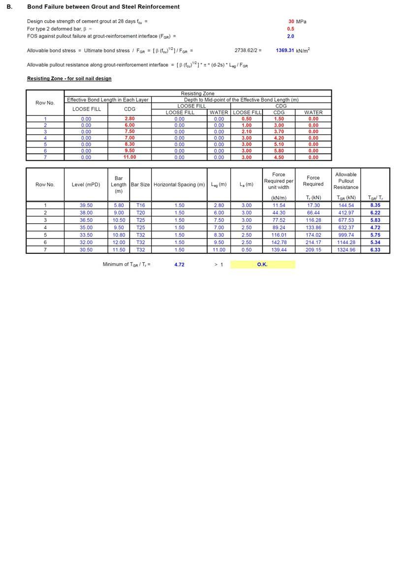
16 16 Description: Loose Fill Bulk Unit Weight = 1800 kg/m m/s 2 = 17.7 kn/m 3 / v = Description: CDG Bulk Unit Weight: 1800 kg/m m/s 2 = 17.7 kn/m 3 Cohesion = 5 kpa Friction Angle = 35 o Figure 2.3 Determination of Earth Pressure Exerted on Grillage Facing upon Liquefaction in Worked Example Design of Soil Nails A hybrid soil nail arrangement with two nail orientations, namely three rows of sub-horizontal nails at 20 to horizontal and four rows of nails at 56 to the horizontal (i.e. perpendicular to slope surface), is adopted in this worked example. The number of sub-horizontal nails is 43% of the total number of nails, which satisfies the initial guidance (Section 5.4 of GEO-HKIE (2011)). The adequacy of this ratio is to be confirmed during the design grillage structure (presented in Section 2.6). The soil nails are assumed to have a spacing of 1.5 m (centre-to-centre) in both the vertical and horizontal directions. The calculations of individual tensile forces to be supported by each row of soil nails are presented in Appendix A.1.1. The minimum diameter and bond length of the soil nails have been determined by considering three internal failure modes, namely tensile failure of the steel bar, bond failure between grout and steel reinforcement and shear failure of adjacent ground of the soil nail. The partial factor for tensile failure of the steel bar has been taken as 1.15 in accordance with Section 7.2 of HKIE (2003), which recommends that the soil nails axial tension capacity is based on the ultimate capacity as specified in BS8110. This is consistent with the Code of Practice for Structural Use of Concrete (BD, 2013). The factors of safety against pullout failure at grout-reinforcement interface and pullout failure at soil-grout interface are taken as 2.0 and 1.5 respectively, according to Table 5.6 of Geoguide 7 (GEO, 2008). It is assumed that the steel bars used in permanent installation are provided with Class 2 corrosion protection measures. Detailed calculations of the size and length of the soil nails are presented in Appendix A.1.2. The final nail arrangement is shown in Figure 2.4.
17 17 Figure 2.4 Soil Nail Arrangement of Worked Example Stability Assessment of the Loose Fill Slope with Soil Nails under Drained Conditions After individual nail forces are determined (as shown in Appendix A.1.1), stability of the nailed slope under drained conditions needs to be verified. This can be assessed by limit equilibrium method assuming that the loose fill is saturated by rainfall infiltration and that the presence of the soil nails avoids liquefaction from triggering. Therefore, in this assessment, the loose fill is represented by the design parameters at the onset of liquefaction (i.e. = 0 kpa and mob = 28 ). In this worked example, this assessment has been carried out using SLOPE/W in which the design nail forces at the intended nail orientations are specified as shown in Figure 2.5. The calculated minimum factor of safety is above 1.4, which is the assumed minimum factor of safety as described in Section 2.2. The design is therefore considered adequate.
18 18 Description: Loose Fill Bulk Unit Weight = 1800 kg/m m/s 2 = 17.7 kn/m 3 Cohesion = 0 kpa Friction Angle = 28 o Description: CDG Bulk Unit Weight = 1800 kg/m m/s 2 = 17.7 kn/m 3 Cohesion = 5 kpa Friction Angle = 35 o Figure 2.5 Stability Assessment of the Loose Fill Slope with Soil Nails under Drained Conditions in Worked Example Design of the Grillage Structure and Soil Nail Heads To minimise the risk associated with uncontrolled liquefaction failure due to squeezing out of liquefied loose fill through the grillage opening, a minimum grillage coverage of 50% of the slope surface is adopted (Sections 2.1 and 5.6 of GEO-HKIE (2011)). The width of all the grillage beams is assumed to be 600 mm. This is equivalent to a surface coverage of 53% which satisfies the design recommendation (calculations are presented in Appendix A.1.3). The grillage beams are assumed to have a depth of 300 mm embedded into the slope surface. The minimum embedment of 300 mm as suggested in Section 5.6 of the GEO-HKIE Report is satisfied. The structural design of the grillage beams is carried out in accordance with the Code of Practice for Structural Use of Concrete (BD, 2013). The assumption that the loose fill is fully liquefied and has reached the steady state undrained shear strength corresponds to the ultimate limit state. A partial factor of 1.0 is therefore adopted for the design of the grillage subjected to the loading generated from the earth pressure upon liquefaction. Each segment of the grillage beams is assumed to be simply supported and is subjected to the action of the earth pressure originated from the liquefied loose fill. Since the earth pressure distribution is assumed to be triangular in shape, the most critical location is normally near the slope toe where the earth pressure is largest. In this worked example, the most critical location is the segment between the sixth and seventh rows of soil nails due to the larger unsupported span length. The reinforcement details are determined by checking the bending moment and shear capacity of the reinforced grillage beams. It should be emphasised that with the hybrid

19 19 nail arrangement, a net tensile force is expected to be induced in the grillage structure due to the upward component of the tensile forces in the sub-horizontal nails. An independent assessment of the structural capacity under combined tension and bending moment is necessary. Figure 2.6 shows the axial force-bending moment interaction diagram for the segment of the grillage beam under consideration. The design is considered adequate as the applied tensile force and bending moment fall inside the interaction diagram. Detailed design calculations of the grillage structure are presented in Appendix A.1.4. Since the soil nail heads are connected to the grillage structure, the guidance for soil-nail head design stipulated in Section of Geoguide 7 (GEO, 2008) does not apply. The minimum size of bearing steel plate is determined by the shear resistance of the concrete. In this example, the steel plate adopted has a plan area of 150 mm 150 mm, and is assumed to be embedded at 250 mm above the base of the grillage beams. Since the grillage beams have a width of 600 mm, the effective size of the soil nail heads can be taken as 600 mm 600 mm. The shear reinforcement details within the soil nail heads are determined by considering punching shear failure of the loaded area in the concrete. Detailed calculations for the soil nail heads are shown in Appendix A.1.5. Compression Tension Figure 2.6 Axial Force - Bending Moment Interaction Diagram of Grillage Beam
20 20 3 Worked Example 2 Design for Steeply Inclined Nails 3.1 Design Scenario and Assumptions The second worked example is to illustrate a design scheme which adopts steeply inclined soil nails at a single orientation with an embedded concrete footing (or toe wall) at the toe of a loose fill slope. The use of hybrid nail arrangement is strongly recommended to enhance the robustness of the system. This example is only relevant for special circumstances whereby the designer may be obliged to design soil nails that are steeply inclined due to site constraints. The use of steeply inclined nails in a loose fill slope may cause excessive movement due to the limited structural stiffness of the steeply inclined nails along the potential sliding direction. The role of the embedded concrete footing is to reduce slope movement upon fill liquefaction (Section 5.5 of GEO-HKIE (2011)). Since the proposed nail arrangement deviates from the recommended hybrid arrangement, an assessment of the effectiveness and robustness of the proposed nail arrangement using numerical analysis technique is required (Section 5.4 of GEO-HKIE (2011)). This is illustrated in this worked example using a commercial finite element program PLAXIS2D. The slope geometry and soil profiles assumed in the second worked example are the same as those in worked example 1, and are presented in Figure 3.1. The assumed design soil parameters are tabulated in Table 3.1. A lower steady state undrained shear strength c ss = 0.2 v kpa is assumed, which is again assumed to be derived directly from site-specific laboratory testing. Other design soil parameters are the same as those adopted in worked example 1. Figure 3.1 Slope Geometry of Worked Example 2
21 21 Table 3.1 Design Soil Parameters in Worked Example 2 Soil Type Parameter Value Loose Fill (Onset of Liquefaction) Loose Fill (After Liquefaction) Bulk Unit Weight, (kn/m 3 ) 17.7 Cohesion, (kpa) 0 Friction Angle, mob ( o ) 28 Bulk Unit Weight, (kn/m 3 ) 17.7 Undrained Shear Strength, c ss (kpa) 0.2 v Friction Angle, ( o ) 0 Bulk Unit Weight, (kn/m 3 ) 17.7 CDG Cohesion, (kpa) 5 Friction Angle, ( o ) Stability Assessment of the Loose Fill Slope without Soil Nails Since the geometry of worked example 2 is the same as that in worked example 1 and that the friction angles at onset of liquefaction of the two cases are also the same (i.e. mob = 28 ), the assessment of the initial stability without soil nails in worked example 2 is identical to that in worked example 1 and is presented in Figure 2.2. The conclusion of the assessment is that the minimum factor of safety is 0.772, which suggests that upgrading works are required. 3.3 Determination of Earth Pressure to be Sustained by Soil Nails The methodology to determine the earth pressure exerted on the slope facing is the same as that described in Section 2.3. Since a lower steady state undrained shear strength of 0.2 v is assumed in this example, a higher earth pressure is expected. As shown in Figure 3.2, the design earth pressure is 87 kpa for a minimum factor of safety of 1.1.

22 22 Description: Loose Fill Bulk Unit Weight = 1800 kg/m m/s 2 = 17.7 kn/m 3 / v = 0.2 Description: CDG Bulk Unit Weight = 1800 kg/m m/s 2 = 17.7 kn/m 3 Cohesion = 5 kpa Friction Angle = 35 o Figure 3.2 Determination of Earth Pressure Exerted on Grillage Facing upon Liquefaction in Worked Example Design of Soil Nails This example assumes that the use of sub-horizontal nails is restricted due to site constraints and steeply inclined soil nails at the same orientation have to be adopted. In theory, the inclination of the soil nails could be determined by considering force equilibrium of the grillage structure taking into account the grillage weight, the design nail forces and the basal shear resistance. However, a low basal shear resistance would imply that the inferred nail orientation would be close to perpendicular to the slope surface. For example, the influence on the nail orientation is only 1 if a basal resistance of 3 kpa is taken into account for the assumed geometry and design nail forces in worked example 2. Moreover, the provision of an embedded concrete footing introduces an unknown reaction force which depends on the mobilised passive soil resistance. This renders the force equilibrium condition of the grillage statically indeterminate. To illustrate the design procedure, the nail orientation is assumed to be perpendicular to the slope surface (i.e. 56 to the horizontal). The soil nails are assumed to have a spacing of 1.5 m (centre-to-centre) in both the vertical and horizontal directions. The calculations of individual nail forces are presented in Appendix A.2.1. The design principle for determination of the diameters and the bond lengths of the soil nails are the same as that described in Section 2.4. Detailed calculations are presented in Appendix A.2.2. The nail arrangement is shown in Figure 3.3.
23 23 Figure 3.3 Soil Nail Arrangement of Worked Example Stability Assessment of the Loose Fill Slope with Soil Nails under Drained Conditions Upon designing the stabilising force to be provided by each row of soil nails, an assessment on the overall stability under drained conditions should be carried out. The analysis is conducted using SLOPE/W, and the results are shown in Figure 3.4. The minimum calculated factor of safety is 4.181, which satisfies the assumed design requirement of a minimum factor of safety of 1.4.

24 24 Description: Loose Fill Bulk Unit Weight = 1800 kg/m m/s 2 = 17.7 kn/m 3 Cohesion = 0 kpa Friction Angle = 28 o Description: CDG Bulk Unit Weight = 1800 kg/m m/s 2 = 17.7 kn/m 3 Cohesion = 5 kpa Friction Angle = 35 o Figure 3.4 Stability Assessment of the Loose Fill Slope with Soil Nails under Drained Conditions in Worked Example Design of Grillage Structure and Soil Nail Heads Despite that larger nail forces are required due to the lower steady state undrained shear strength, the size of the grillage structure is the same as that adopted in worked example 1. In other words, the grillage beams have a width of 600 mm and a depth of 300 mm embedded into the slope surface. The calculations of minimum coverage area are presented in Appendix A.2.3. The structural design procedure for the grillage facing and soil nail heads are similar to that adopted in worked example 1. The calculations are presented in Appendix A.2.4 and A.2.5 for the grillage beams and soil nail heads respectively. To minimise the overall slope movement, an embedded concrete footing is adopted. A nominal embedment depth of 1 m has been adopted for the embedded footing. The predicted performance of the nailed slope, with and without the embedded footing is assessed by numerical analysis and is presented in Section 3.7. The numerical analysis can also provide the shear force and bending moment induced in the concrete footing for structural design, which can be carried out in accordance with the Code of Practice for Structural Use of Concrete (BD, 2013). The design structural forces for the embedded concrete footing are shown in Appendix A.2.5.
. The model geometry is shown in Figure 3.")
25 Slope Deformation Assessment by Numerical Analysis To demonstrate the robustness of the proposed nail arrangement which involves the use of steeply inclined nails augmented by an embedded concrete footing, a finite element analysis has been performed using two-dimensional finite element program PLAXIS2D (version 9.0.2). The model geometry is shown in Figure 3.5, which is identical to that presented in Figure 3.1. The slope geometry and nail orientation are essentially the same as the case considered in Section of the GEO-HKIE (2011). According to GEO-HKIE (2011), larger structural movement may be incurred under interface liquefaction compared to full liquefaction if steeply inclined nails are adopted only. Therefore, the interface liquefaction scenario is considered more critical as far as slope deformation is concerned. Numerical model is used to study the effectiveness of the soil nail design against the interface liquefaction. For design of slopes of other geometry, numerical study for the full liquefaction scenario should also be undertaken. In the numerical model, interface liquefaction is modelled by the sudden reduction of shear resistance in a 0.5 m thick of loose fill at a depth of 3 m under undrained conditions. Distance (m) Grillage Beam Elevation (mpd) Design Perched Water Table Soil Nails in Liquefied Loose Fill Toe Embedment Soil Nails in Competent Figure 3.5 Model Geometry and Initial Pore Water Pressure Distribution in the Numerical Model In the numerical model, both loose fill and CDG are modelled as an elastic-perfectly plastic soil model with a Mohr-Coulomb failure criterion. The model parameters for soils are tabulated in Table 3.2. For the loose fill, the Young s modulus (E) is assumed to be 5 MPa and a Poisson s ratio ( ) of 0.3 is assumed. Two sets of strength parameters have been used to represent the soil states before and after liquefaction. Before liquefaction, effective strength parameters of = 5 kpa and = 35 have been assigned to establish the initial stresses (see Figure 3.6). Upon liquefaction, an undrained model is used to mimic the
26 26 loss of shear resistance under constant volume conditions. The effective stiffness parameters (i.e. E and ) remain the same, and the corresponding undrained values are calculated in PLAXIS2D automatically. The steady state undrained shear strength is a function of initial effective vertical stress (i.e. c ss = 0.2 v ). The bottom 0.5 m of loose fill layer is assigned an undrained shear strength calculated from the effective vertical stress at the mid-depth of the layer as shown in Figure 3.7. The loose fill on top of the liquefied layer is represented by soil parameters at the onset of liquefaction (i.e. = 0 kpa and = 28 ). The 1 m toe embedment is modelled as an elastic material with a Young s modulus (E) of 22 GPa and a Poisson s ratio ( ) of 0.2.
27 27 Table 3.2 Model Parameters for Soils in the Numerical Analysis Soil Type Model Type Parameter Loose Fill (Before Liquefaction) Elastic-Perfectly Plastic Model with Mohr-Coulomb failure Criterion (Drained) Input Value Bulk Unit Weight, (kn/m 3 ) 17.7 Cohesion, (kpa) 5 Friction Angle, ( ) 35 Young s Modulus, E (kpa) 5,000 Poisson s Ratio, 0.3 Loose Fill (After Liquefaction) Loose Fill (Non-liquefied) CDG Toe Embedment Elastic-Perfectly Plastic Model with Mohr-Coulomb Failure Criterion (Undrained) Elastic-Perfectly Plastic Model with Mohr-Coulomb Failure Criterion (Drained) Elastic-Perfectly Plastic Model with Mohr-Coulomb Failure Criterion (Drained) Elastic Model Bulk Unit Weight, (kn/m 3 ) 17.7 Undrained Shear Strength, c ss (kpa) 3.0 to 8.3 *Young s Modulus, E (kpa) 5,000 *Poisson s Ratio, 0.3 Bulk Unit Weight, (kn/m 3 ) 17.7 Cohesion, (kpa) 0 Friction Angle, ( ) 28 Young s Modulus, E (kpa) 5,000 Bulk Unit Weight, (kn/m 3 ) 17.7 Cohesion, (kpa) 5 Friction Angle, ( ) 35 Young s Modulus, E (kpa) 25,000 Poisson s Ratio, 0.3 Bulk Unit Weight, (kn/m 3 ) 24 Young s Modulus, E (kpa) Poisson s Ratio, 0.2 *Notes: These are drained parameters. The corresponding undrained parameters are automatically calculated in PLAXIS2D.


28 28 Loose Fill before Liquefaction c = 5 kpa = 35 o CDG c = 5 kpa = 35 o Figure 3.6 Shear Strength Parameters of the Loose Fill before Interface Liquefaction Non-liquefied Loose Fill c = 0 kpa = 28 o Liquefied Loose Fill c ss = 4.8 kpa CDG c = 5 kpa = 35 o Liquefied Loose Fill c ss = 8.3 kpa Liquefied Loose Fill c ss = 3.0 kpa Figure 3.7 Undrained Shear Strength of the Loose Fill after Interface Liquefaction
29 29 The soil nails are modelled as a combination of node-to-node anchor element and geogrid element as illustrated in Figure 3.5. The geogrid element, which considers interaction between the structural element and the surrounding soil, is used to model the bond length of the soil nail. On the other hand, the node-to-node anchors are spring elements which ignore the interaction with the surrounding soil along its length. They are appropriate for modelling the portion of the soil nail within the loose fill due to possible flow behaviour of the liquefied loose fill around the soil nails (Appendix B.2 of GEO-HKIE (2011)). The maximum mobilised tensile force in each soil nail is limited according to the tensile strength of the steel bar. In order to model the soil nails in a plane strain model, the axial stiffness (EA) is scaled down by the soil nail spacing of 1.5 m. The grillage facing is modelled as a plate element characterised by its axial stiffness (EA) and bending stiffness (EI). The structural parameters adopted in the analysis are tabulated in Table 3.3. The purpose of conducting the numerical analysis is to demonstrate the effectiveness of the proposed nail arrangement. Therefore the focus of the assessment should be placed on whether sufficient nail forces could be mobilised under the assumed loading conditions (i.e. interface liquefaction) and the associated slope deformation. Comparison of design nail forces and mobilised nail forces calculated from the numerical analyses is presented in Figure 3.8. It shows that the mobilised nail forces in interface liquefaction are less than the forces assumed for the full liquefaction. However, since the calculated deformation is limited, the design is considered acceptable. The acceptance criteria for slope deformation should be determined on a site-specific basis taking into account the tolerable movements of any sensitive receivers in close proximity to the slope. The predicted deformation pattern of worked example 2 with and without the toe embedment is presented in Figure 3.9. The input parameters and numerical results of the analysis are presented in Appendix A.2.6. Table 3.3 Model Parameters for Soil Nails and Grillage Facing in the Numerical Analysis Structural Type Model Type Parameter Input Value Soil Nail Node-to-node Anchor and Geogrid Axial Stiffness, EA (kn/m) Maximum Compressive Force, F max, comp (kn/m) Maximum Tensile Force, F max, tens (kn/m) T16: 26,808 T20: 41,867 T25: 65,467 T32: T40: T16: 61.7 T20: 96.3 T25: T32: T40: Axial Stiffness, EA (kn/m) Grillage Facing Plate Bending Stiffness, EI (knm 2 /m) 19,980 Weight, w (kn/m 2 ) 3.5 Poisson s Ratio, 0.2
30 30 +ve: in Tension -ve: in Compression Figure 3.8 Comparison of Design Nail Forces and Mobilised Nail Forces upon Interface Liquefaction
31 31 Max. Slope Deformation = 108 mm (a)with Toe Embedment Max. Slope Deformation = 129 mm (b)without Toe Embedment Figure 3.9 Slope Deformation Predicted by the Numerical Analysis
32 32 4 Worked Example 3 Design for Deep Fill Profile 4.1 Design Scenario and Assumptions Loose fill at great depths is less likely to undergo static liquefaction. In Section 5.3 of the GEO-HKIE Report, a procedure is proposed to delineate the zone of loose fill that can be assumed to be non-liquefiable. During stability assessment, the shear resistance of the non-liquefiable fill can be represented by the friction angle at the onset of liquefaction. This would reduce the predicted earth pressure exerted on the grillage facing and hence the required soil nail forces, although the bond strength in this zone has to be ignored. In the third worked example, a loose fill slope with a deep fill layer is considered to illustrate the design procedure. The design problem considers a 10 m high loose fill slope at an inclination of 33.7 (i.e. 1:1.5) to the horizontal (see Figure 4.1). The loose fill layer has a maximum depth of 6 m deep near the crest of the slope. A design groundwater table (DGWT) at about one-third of the slope height is assumed together with a design perched water table (DPWT) at 1 m above the loose fill / CDG interface. The design soil parameters are tabulated in Table 4.1, which are basically the same as those assumed in worked example 1. For the zone of loose fill which is identified to be non-liquefiable (discussed in Section 4.2), the shear strength parameters are the same as those at the onset of liquefaction for stability assessment purposes. Table 4.1 Design Soil Parameters in Worked Example 3 Soil Type Parameter Value Loose Fill (Onset of Liquefaction or Non-liquefiable fill) Loose fill (After Liquefaction) Bulk Unit Weight, (kn/m 3 ) 17.7 Cohesion, (kpa) 0 Friction Angle, mob ( o ) 28 Bulk Unit Weight, (kn/m 3 ) 17.7 Undrained Shear Strength, c ss (kpa) v Friction Angle, ( o ) 0 Bulk Unit Weight, (kn/m 3 ) 17.7 CDG Cohesion, (kpa) 5 Friction Angle, ( o ) 35
33 33 Figure 4.1 Slope Geometry of Worked Example Delineation of Non-liquefiable Loose Fill Zone Limit equilibrium method is used to delineate the zone of loose fill which can be assumed to be non-liquefiable (Section 5.3 of GEO-HKIE (2011)). The calculations have been carried out by SLOPE/W as shown in Figure 4.2. In the analyses, the entire loose fill zone is represented by the drained friction angle corresponding to the onset of liquefaction (i.e. mob = 28 ). A number of planar slip surfaces drawn from the slope toe at different inclinations are specified. It should be noted that these planar slip surfaces must fall entirely within the fill layer. The procedure is not applicable if the assumed slip surface intercepts the soil layer underneath the fill. Assuming that a minimum factor of safety of 1.4 is required for this slope, the zone of non-liquefiable fill would be that bounded above by the slip surface which gives a factor of safety of 1.4 (i.e. slip surface 5 in Figure 4.2). Since the other slip surfaces above give a factor of safety below 1.4, upgrading works are required. 4.3 Determination of Earth Pressure to be Sustained by Soil Nails Once the zone of non-liquefiable fill has been identified, the design procedure that follows is similar to that illustrated in worked example 1. The earth pressure exerted on the grillage facing is determined by limit equilibrium analysis using the design soil parameters listed in Table 4.1. Steady state undrained shear strength is assumed in the liquefiable fill only as presented in Figure 4.3.
 Bulk Unit Weight = 1800 kg/m 3 9.81m/s 2 = 17.")

34 34 Description: Loose Fill Bulk Unit Weight = 1800 kg/m m/s 2 = 17.7 kn/m 3 Cohesion = 0 kpa Friction Angle = 28 o Description: CDG Bulk Unit Weight = 1800 kg/m m/s 2 = 17.7 kn/m 3 Cohesion = 5 kpa Friction Angle = 35 o Figure 4.2 Delineation of Non-liquefiable Loose Fill Zone Description: Loose Fill (non-liquefiable) Bulk Unit Weight = 1800 kg/m m/s 2 = 17.7 kn/m 3 Cohesion = 0 kpa Friction Angle = 28 o Description: Loose Fill (Liquefiable) Bulk Unit Weight = 1800 kg/m m/s 2 = 17.7 kn/m 3 / v = Description: CDG Bulk Unit Weight = 1800 kg/m m/s 2 = 17.7 kn/m 3 Cohesion = 5 kpa Friction Angle = 35 o Figure 4.3 Determination of Earth Pressure Exerted on Grillage Facing upon Liquefaction in Worked Example 3
35 Design of Soil Nails A hybrid nail arrangement is adopted in this worked example. Similar to the design scheme adopted in worked example 1, the top three rows of soil nails are assumed to be sub-horizontal (i.e. inclined at 20 to the horizontal), whilst the remaining four rows of soil nails are inclined at 56 to the horizontal. This implies that the number of sub-horizontal nails is 43% of the total number of nails, which satisfies the initial guidance (Section 5.4 of GEO-HKIE (2011)). The adequacy of this ratio is to be confirmed during the design of the grillage structure (presented in Section 4.6). The soil nails are assumed to have a spacing of 1.5 m (centre-to-centre) in both the vertical and horizontal directions. The calculations of individual tensile forces to be supported by each row of soil nails are presented in Appendix A.3.1. The calculations of diameters and bond lengths of the soil nails are presented in Appendix A.3.2. It should be emphasised that the bond strength along the soil nails in the non-liquefiable zone has to be ignored (Section 5.3 of GEO-HKIE (2011)). The final nail arrangement is presented in Figure 4.4. Figure 4.4 Soil Nail Arrangement of Worked Example 3

36 Stability Assessment of the Loose Fill Slope with Soil Nails under Drained Conditions The stability of the nailed loose fill slope is assessed again after individual nail forces are determined by limit equilibrium method as shown in Figure 4.5. Description: Loose Fill Bulk Unit Weight = 1800 kg/m m/s 2 = 17.7 kn/m 3 Cohesion = 0 kpa Friction Angle = 28 o Description: CDG Bulk Unit Weight = 1800 kg/m m/s 2 = 17.7 kn/m 3 Cohesion = 5 kpa Friction Angle = 35 o Figure 4.5 Stability Assessment of the Loose Fill Slope with Soil Nails under Drained Conditions in Worked Example Design of Grillage Structure and Soil Nail Heads The design of the grillage facing is similar to that adopted in worked example 1 which consists of grillage beams with a width of 600 mm and a thickness of 300 mm. The calculations of the coverage area are presented in Appendix A.3.3. The structural design calculations of the grillage beams are presented in Appendix A.3.4, whilst the design calculations for the soil nail heads are given in Appendix A.3.5. To confirm that the number of sub-horizontal nails is sufficient to support the weight of the grillage, force equilibrium of the grillage structure is considered. The calculations are presented in Appendix A.3.6.
37 37 5 Discussion The draft version of this report issued in April 2013 was circulated for comments among government departments and practitioners via HKIE-GD. The comments received have been incorporated in the final version of this report issued in October This Section highlights a few salient points which deserve special attention from designers. The comments and responses are attached in Appendix B. 5.1 Limit Equilibrium Analyses An important step in the design procedure is to determine the required stabilising pressure on the slope facing using limit equilibrium method. The magnitude of a set of concentrated point loads distributed in a triangular shape representing the earth pressure can be determined. In theory, the triangular earth pressure should be modelled using as many point loads as possible. However, if too many point loads are used, the trial-and-error procedure to identify the required stabilising pressure would become impracticable. A simple case of a 10 m high slope has been considered to illustrate that 10 nos. of point loads are sufficient to limit the discrepancy to within 3% (see Comments and Responses on Page 89). For other design conditions, designers should make their own engineering judgement to determine the minimum number of point loads to represent the earth pressure. In addition, when the Grid and Radius Method is employed in slope stability analysis, the designer should bear in mind that the slip surface should embrace all the point loads exerted on the slope surface. If the critical slip surface does not embrace all the point loads on the slope surface, omission of some point loads may lead to underestimation of the loading condition. 5.2 Irregular Slope Profile The purpose of this study is to demonstrate the implementation of the new recommendations given in the GEO-HKIE (2011) Report, therefore the slope geometry considered in the three worked examples is simplified. In reality, the slope profile may sometimes be irregular. In this case, the designer should use the actual slope profile to determine the earth pressure exerted on the facing structure. The earth pressure exerted on the facing structure should be assumed to be acting in the normal direction of the slope surface since very small shear stress can be mobilised along the interface between the facing and the loose fill. The small shear stress has already been taken into consideration by the assumed basal shear force. Therefore the earth pressure must be normal to the slope surface. When applying the stabilising point loads, one should consider if the proposed soil nail arrangement would be able to provide the assumed stabilising effects. For example the downward force exerted on the slope berm is unrealistic as no nail force would be mobilised in this direction, and stabilisation force applied on slope berm should be neglected for design purposes. 5.3 Delineation of Non-liquefiable Loose Fill Zone The thickness of loose fill may vary. For the case where the thickness of the loose fill increases with height, similar to the one illustrated in Fig. 4.2, a linear slip surface can be
38 38 used to delineate the non-liquefiable zone. For the case where the thickness of loose fill decreases towards the slope crest, the non-liquefiable zone can be identified by assuming linear or bi-linear slip surfaces provided that these slip surfaces fall entirely within the loose fill zone (see Comments and Responses on Page 91). The liquefiable zone refers to the zone above the slip surface which has a minimum FOS of Structural Design of Grillage Structure In the three worked examples presented in this report, structural design of the grillage was carried out by considering a segment of the grillage near the slope toe. For simplicity, the grillage beam is assumed to be simply supported, and is subjected to a uniformly distributed load. In theory, a continuous beam representing the entire facing structure should be used to determine the structural forces when a triangular pressure is exerted on the facing. A parametric study based on the soil nail arrangement of worked example 2 has been conducted to examine the possible discrepancies produced by the two different approaches described above (i.e., simply supported with uniformly distributed load and continuous beam with a triangular pressure). It is found that the calculated maximum bending moment is in general larger in the case of a simply supported beam with a uniformly distributed load for the conditions considered. The shear forces calculated from the two approaches are comparable in the worked example, with a percentage difference in the order of 1% in general. It can be concluded that simplifying the grillage as segments of simply supported beams is generally acceptable. However, designers should verify this approach on a case-by-case basis.
39 39 6 Conclusions Three worked examples have been prepared and presented to illustrate the recommended procedure for designing soil nails to upgrade loose fill slopes. The design scenarios considered in these worked examples are relatively simple as the key objective is to demonstrate the use of hybrid nail arrangement which is recommended for enhanced system robustness. The adopted hybrid nail arrangement has been demonstrated through numerical modelling techniques to be sufficiently robust. For other proposed nail arrangements, e.g. similar to that adopted in worked example 2, designers are required to demonstrate the robustness of the proposed scheme. Particular focus should be placed on the nail force mobilisation mechanisms and the associated mobilised deformation.
40 40 7 References BD (2013). Code of Practice for Structural Use of Concrete. Buildings Department, Hong Kong, 187 p. GCO (1984). Geotechnical Manual for Slopes. (2 nd Edition). Geotechnical Control Office, Civil Engineering Services Department, Hong Kong, 295 p. GEO (1993). Guide to Retaining Wall Design (Geoguide 1). Second Edition. Geotechnical Engineering Office, Civil Engineering Department, Hong Kong, 258 p. GEO (2008). Guide to Soil Nail Design and Construction (Geoguide 7). Geotechnical Engineering Office, Civil Engineering and Development Department, Hong Kong, 97 p. GEO-HKIE (2011). Design of Soil Nails for Upgrading Loose Fill Slopes. Geotechnical Engineering Office, Civil Engineering and Development Department, Hong Kong and The Hong Kong Institution of Engineers (Geotechnical Division), 96 p. HKIE (2003). Soil Nails in Loose Fill Slopes. A Preliminary Study (Final Report). The Hong Kong Institution of Engineers (Geotechnical Division), 88 p.
41 41 Appendix A Detailed Design Calculations of Worked Examples
42 42 Contents Contents 41 A.1 Detailed Design Calculation of Worked Example 1 42 A.1.1 Calculations of Individual Nail Forces 42 A.1.2 Soil Nail Design Calculations 43 A.1.3 Percentage Coverage of Grillage Facing 46 A.1.4 Structural Design Calculations of Grillage Facing 47 A.1.5 Structural Design Calculations of Soil Nail Heads 49 A.1.6 Force Equilibrium Assessment of Grillage Facing 50 A.2 Detailed Design Calculation of Worked Example 2 51 A.2.1 Calculations of Individual Nail Forces 51 A.2.2 Soil Nail Design Calculations 52 A.2.3 Percentage Coverage of Grillage Facing 55 A.2.4 Structural Design Calculations of Grillage Facing 56 A.2.5 Structural Design Calculations of Soil Nail Heads 58 A.2.6 Numerical Analysis for Slope Performance Assessment 59 A.3 Detailed Design Calculation of Worked Example 3 69 A.3.1 Calculations of Individual Nail Forces 69 A.3.2 Soil Nail Design Calculations 70 A.3.3 Percentage Coverage of Grillage Facing 73 A.3.4 Structural Design Calculations of Grillage Facing 74 A.3.5 Structural Design Calculations of Soil Nail Heads 76 A.3.6 Force Equilibrium Assessment of Grillage Facing 77 Page No.
43 43 A.1 Detailed Design Calculation of Worked Example 1 A.1.1 Calculations of Individual Nail Forces
44 A.1.2 Soil Nail Design Calculations 44
45 45
46 46
47 47 A.1.3 Percentage Coverage of Grillage Facing
48 48 A.1.4 Structural Design Calculations of Grillage Facing
49 49
50 50 A.1.5 Structural Design Calculations of Soil Nail Heads
51 51 A.1.6 Force Equilibrium Assessment of Grillage Facing
52 52 A.2 Detailed Design Calculation of Worked Example 2 A.2.1 Calculations of Individual Nail Forces
53 A.2.2 Soil Nail Design Calculations 53
54 54
55 55
56 56 A.2.3 Percentage Coverage of Grillage Facing
57 57 A.2.4 Structural Design Calculations of Grillage Facing
58 58
59 59 A.2.5 Structural Design Calculations of Soil Nail Heads

60 60 A.2.6 Numerical Analysis for Slope Performance Assessment A Model Geometry Distance (m) Elevation (mpd)
 c ref : Cohesion (kn/m 2 ) Friction Angle ( o ) Dilatancy Angle ( o")
61 61 A Model Parameters (Soil) Glossary of Symbols: sat : Bulk Unit Weight Saturated (kn/m 3 ) Poisson s Ratio E ref : Young s Modulus (kn/m 2 ) c ref : Cohesion (kn/m 2 ) Friction Angle ( o ) Dilatancy Angle ( o )
62 62 A Model Parameters (Grillage Facing) Glossary of Symbols: EA : Axial Stiffness (kn/m) EI: Flexural Rigidity (knm 2 /m) w: Weight (kn/m 2 ) Poisson s Ratio M p : Maximum Bending Moment (knm/m) N p : Maximum Axial Force (kn/m)
 F max,tens : Maximum Tensile Force (kn/m) Bond Length of Soil Nails Glossary of Symbols: EA : Axial Stiffness (kn/m) N p : Maximum Axial Tension Force")
63 63 A Model Parameters (Soil Nails) Free Length of Soil Nails Glossary of Symbols: EA : Axial Stiffness (kn/m) F max,comp : Maximum Compressive Force (kn/m) F max,tens : Maximum Tensile Force (kn/m) Bond Length of Soil Nails Glossary of Symbols: EA : Axial Stiffness (kn/m) N p : Maximum Axial Tension Force (kn/m)
64 64 A Model Parameters (Toe Embedment) Glossary of Symbols: sat : Bulk Unit Weight Saturated (kn/m 3 ) Poisson s Ratio E ref : Young s Modulus (kn/m 2 )
 Elevation")
65 65 A Material Sets before Liquefaction Distance (m) Elevation (mpd)
66 66 A Pore Water Pressure Distribution before Liquefaction Distance (m) DPWT: Design Perched Water Table Elevation (mpd) 1 m DPWT (For details, please refer to Figure 3.3) Max. Pore Pressure = 11 kn/m 2

 Elevation (mpd) 5")
67 67 A Material Sets after Liquefaction Distance (m) Elevation (mpd) 5 Toe embedment
 Elevation (mpd) Max.")
68 68 A Pore Water Pressure Distribution after Liquefaction Distance (m) Elevation (mpd) Max. Excess Pore Pressure = 80 kn/m 2
 Elevation (mpd) Max.")
69 69 A Slope Deformation after Liquefaction Distance (m) Elevation (mpd) Max. Slope Deformation = 108 mm
70 70 A.3 Detailed Design Calculation of Worked Example 3 A.3.1 Calculations of Individual Nail Forces
71 A.3.2 Soil Nail Design Calculations 71
72 72
73 73
74 74 A.3.3 Percentage Coverage of Grillage Facing

75 75 A.3.4 Structural Design Calculations of Grillage Facing
76 76
77 77 A.3.5 Structural Design Calculations of Soil Nail Heads
78 78 A.3.6 Force Equilibrium Assessment of Grillage Facing
79 79 Appendix B Responses to Comments on Draft Report issued in April 2013
80 Design Illustrations on the Use of Soil Nails to Upgrade Loose Fill Slopes Responses to Comments 80 GEO/CEDD Comments Responses 1. Section 1.2(c) (P.10) According to Section 5.4 of GEO-HKIE Report, the sub-horizontal nails are provided to counter sliding failure due to interface liquefaction. The sentence The number of sub-horizontal nails is considered appropriate if it is sufficient to support the weight of the grillage upon fill liquefaction is misleading. 1. According to Section 5.4 of GEO-HKIE (2011), the ratio of sub-horizontal nails to steeply inclined nails can be estimated by considering force equilibrium of the grillage facing. The number of sub-horizontal nails should be approximately 40% to 50% of the total number of soil nails to ensure sufficient sub-horizontal nails are present to counter sliding failure. To avoid misunderstanding, the sentence The number of sub-horizontal nails is considered appropriate if it is sufficient to support the weight of the grillage upon fill liquefaction has been replaced by the above sentences. 2. Section 3.6 (P.23) The design calculation for the embedded concrete footing including the required reinforcement should be given in worked example The purpose of these worked examples is to illustrate the new design recommendations highlighted in GEO-HKIE (2011). The structural design of the embedded footing can be carried out according to the guidelines in Code of Practice for Structural Use of Concrete 2004 (Second Edition) as for typical reinforced concrete structures. This is explained in Section 3.6 as follows: The numerical analysis can also provide the shear force and bending moment induced in the concrete footing for structural design which can be carried out in accordance with the Code of Practice for Structural Use of Concrete (BD, 2004). The design structural forces for worked example 2 are shown in Appendix A.2.5.
81 81 Comments 3. Section 3.7 (P.23-P.29) Only interface liquefaction scenario has been considered in worked example 2. In fact, both full liquefaction and interface liquefaction failure modes should be checked in order to demonstrate the robustness of the proposed nail arrangement. The mobilized nail forces upon full liquefaction should also be plotted in Figure 3.9 for comparison. 4. In Figures 2.3 & 3.2, there are failure slips (no. 4 of each figure) across the CDG stratum and the "upgraded" FOS of these slips are indicated (i.e. FOS of and in Figures 2.3 and 3.2 respectively). Given the potential failure mode for landslips across the CDG stratum is different from liquefaction of loose fill concerned in these worked examples and those nails orientated perpendicular to the slope surface are hard to mobilise in case the CDG fails, please consider whether it is appropriate to present the "upgraded" FOS of the slips across the CDG stratum in these figures. 5. Some characters in the Figures (e.g. Figure 4.5) may be too small to read if the pages are printed in A4 paper. 6. It is suggested to demonstrate the derivation of the css/s'v ratio from triaxial test results in one of the worked examples. Responses 3. Worked example 2 is based on the same slope geometry and nail orientation adopted in Section of GEO-HKIE (2011). As discussed in Section of GEO-HKIE (2011), larger structural movement may be incurred under interface liquefaction compared to full liquefaction if steeply inclined nails are adopted only. Therefore, the interface liquefaction scenario was considered more critical as far as slope deformation is concerned for worked example 2. This explanation has added to Section The failure slip no. 4 in Figure 2.3 & 3.2 has been deleted. 5. Noted. Characters in figures have been enlarged. 6. The purpose of these worked examples is to illustrate the new design recommendations highlighted in GEO-HKIE (2011). For the derivation of the c ss /p peak ratio, reference can be made to HKIE (2003). 7. It is suggested to include the reinforcement details/configuration of grillage beams, soil nail heads 7. It is not the intention of this report to illustrate the structural detailing of grillage beams, soil nail heads and embedded concrete footings.
82 82 Comments and embedded concrete footings in the worked examples. 8. Worked Example 2: It is noted that an embedded concrete footing of 1m depth is adopted to minimize the overall slope movement. It is suggested to include the detailed design of the concrete footing and the connection details between the concrete footing and the grillage beam in the worked example. 9. In Section 1.2, subsection (a), Please clarify whether this step is referring to Section 3.2 of GEO-HKIE (2011). If so, please state it in Section 1.2 for clarity. 10. In Section 2.4, it is mentioned that the partial factor for tensile failure of the steel bar has been taken as 1.15 in accordance with Section 7.2 of HKIE (2003). However, in Table 5.6 of Geoguide 7 (2008), a factor of 1.5 is recommended. Some justifications for adopting a smaller FOS should be given. Responses 8. The structural design of the embedded footing can be carried out according to relevant structural design standards such as Code of Practice for Structural Use of Concrete This is explained in Section 3.6 as follows: The numerical analysis can also provide the shear force and bending moment induced in the concrete footing for structural design which can be carried out in accordance with relevant structural design standards. The design structural forces for worked example 2 are shown in Appendix A Section 1.2 (a) refers to Section 3.2 of GEO-HKIE (2011). This section has been revised as follows for clarity: Determine if slope upgrading works are required in respect of static liquefaction (Section 3.2 of GEO-HKIE (2011)) the stability of the loose fill slope is examined under drained conditions using soil parameters corresponding to the onset of liquefaction ( mob ). 10. Section of Geoguide 7 states that the use of soil nails in loose fill slopes should in-principle follow the recommendations given in Study Report on Soil Nails in Loose Fill prepared by the HKIE (HKIE, 2003), whilst Section 7.2 of the HKIE (2003) report recommends that the soil nail axial tension capacity should base on the ultimate capacity (not characteristic yield strength) as defined in accordance with BS Therefore the approach of using partial factor of 1.15 is considered appropriate. This justification is given in Section 2.4 of the report.
83 83 Comments 11. Also in Section 2.4, line 8 of paragraph 2, please clarify whether the term ground-reinforcement interface should be read as grout-reinforcement interface. 12. In A.1.1, Row 1 is missing in the soil-nail table. 13. In Section 2.4, the assumption of the corrosion class, e.g. Class 2, should be stated for clarity as this would affect the design strength of the soil-nail. 14. In P.28, there is no noticeable difference between the two figures. Please enlarge the critical zone and/or assign movement contour for better illustration. 15. The step detailed in Section 4.2 should be a general design procedure for fill slope which has deep loose fill. As such, a step for delineating the non-liquefiable loose fill zone should be added in Section 1.2 for completeness. 16. In A , there is no indication of whether the deformation diagram is under the situation where there is a toe wall or not. 17. The report on the hybrid arrangement (GEO-HKIE, 2011) recommends use of numerical analysis to check effectiveness of the system if the nail arrangement "deviates significantly" from the illustrative example given in the report. The illustrative examples given in this report are more or less the same as that shown in the Responses 11. The term in line 8 of paragraph 2 in Section 2.4 should read as grout-reinforcement interface. This has been revised. 12. Noted. Appendix A.1.1 has been revised. 13. This section has been revised as follows for clarity: It is assumed that the steel bars used in permanent installation are provided with Class 2 corrosion protection measures. 14. Figures in P.28 have been revised for better illustration. 15. The following sentence has been added in Section 1.2 (a) as follows: For deep fill, liquefiable and non-liquefiable zones can be delineated using mob following the procedure described in Section 5.3 of GEO-HKIE (2011). 16. Noted. The figure is enlarged and a label has been added in the figure to indicate the location of embedded concrete footing. 17. The purpose of the worked examples is to illustrate the new design recommendations highlighted in GEO-HKIE (2011). It is not the intention of this report to cover all possible scenarios with regard to site constraints. Nonetheless, the use of steeply inclined nail arrangement in worked example 2 reflects a common problem encountered in Hong Kong whereby sub-horizontal nails cannot be installed due to site constraint.
84 84 Comments 2011 report. They could not illustrate cases where nail arrangement has to be varied because of site condition (e.g. a private lot close to slope crest constraints the use or length of horizontal nails etc) in shallow/deep fills or if the height is much higher than 10 m, say 20 m, etc. 18. Page 10, 1.2(b)-To better tally with the recommendations given in GEO-HKIE (2011) and to clearly spell out the objective of the treatment in Slope/W, suggest to insert on line 15 the sentence marked in red and to amend the follow-up sentence as shown: The distribution of the earth pressure can be assumed to be triangular in shape and can be modelled by a series of equivalent concentrated forces acting in the normal direction of the slope surface. It is important that the stabilising pressure specified should not lead to an increase in shear strength of the fill in slope stability calculations. The use of equivalent concentrated forces, rather than a distributed surface pressure, will avoid the increase in the undrained shear strength of the loose fill in Slope/W program (Section 5.2 of GEO-HKIE (2011)). 19. Page 11, 1.2(e) - It is currently suggested in the last sentence that "A minimum grillage embedment of 0.3 m, which can be provided by back-filling, is considered adequate (Section 5.6 of GEO-HKIE (2011))." It is not apparent in GEO-HKIE (2011) that the 0.3 m depth grillage embedment can be provided by back-filling. Additional surcharge to loose fill may cause further settlement of the fill body. This recommendation should be further reviewed. Responses 18. Section 1.2 (b) has been revised as follows: It is important that the stabilising pressure specified should not lead to an increase in shear strength of the fill in slope stability calculations. The use of equivalent concentrated forces, rather than a distributed surface pressure, will avoid the increase in the undrained shear strength of the loose fill in some commercial computer programs (Section 5.2 of GEO-HKIE (2011)). 19. We agree that GEO-HKIE (2011) does not explicitly state that the 0.3 m depth grillage embedment can be provided by back-filling. Therefore the last sentence in Section 1.2 (e) has been revised as follows: A minimum grillage embedment of 0.3 m is considered adequate (Section 5.6 of GEO-HKIE (2011)). The settlement involved should be minimal.
85 85 Comments 20. Page 27, Table A very large compressive strength is being specified for the soil nails in the Plaxis model. Why should the compressive strength of the model nails be excessively greater than its tensile strength? 21. Page 31, Figure Should the line delineating the critical 'planar slip surface' at 21 be labelled? Please review the profile of the DGWT that intercept the two ground strata (loose fill and CDG), as the two strata are likely to have a huge contrast in permeability. 22. A1.4, A2.4 and A3.4 Design of Shear Reinforcement for Grillage System. The design shear force has been taken as 0.5 of the UDL x beam span (assuming a simply supported beam?). Please note that the maximum shear force for a continuous beam can be of the UDL x beam span, which is 25% higher than that for a simply supported beam. Responses 20. The purpose of using a large maximum compressive capacity in the soil nail is to allow development of compressive force, if any, in the nail. In theory the calculated compressive force should be checked against the buckling capacity of the soil nail. However in this worked example, the calculated compressive forces are very small. Explicit checking is not required. 21. The delineating line in Figure 4.1 has been labelled. The main groundwater table is governed by the local hydrogeological conditions. In this worked example, the adopted design groundwater table (DGWT) is an assumption to illustrate the design procedure for a main groundwater table as compared to a perched water table. A design perched water table has also been added to reflect the contrast on soil permeability at the loose fill / CDG interface. 22. In theory, structural forces should be calculated assuming a continuous beam subjected to a triangular pressure. For simplicity, the grillage segment with the longest span is chosen for structural design and the loading is simplified as a uniformly distributed load (i.e. u = 76 kpa between rows 6 & 7 of soil nail if the maximum earth pressure is 87 kpa as shown in Worked Example 2). Therefore, calculations for the simply supported assumption yield the following results: Bending Moment, M = u nail spacing L 2 / 8 = knm Shear Force, V = u nail spacing L / 2 = kn A simple structural analysis has been performed for a continuous beam and the results show that the maximum shear force induced in a simply supported beam (i.e kn) and that in a continuous beam (i.e
86 86 Comments Responses kn) are comparable, with a difference of 1% (see Appendix B.1.1 on Page 93). To examine if the discrepancy significantly changes with loading conditions, a series of further structural analyses have been performed for a continuous beam with different magnitudes of triangular pressure varying from 50 kpa to 1000 kpa. The calculated shear forces are compared with those obtained from simply supported assumptions. The results show that the maximum shear force in a simply supported beam and that in a continuous beam are comparable, with a percentage difference in the order of 1% in the worked example concerned (see Appendix B on Pages 96-97). Designers are reminded to carry out necessary verification (see Section 5.4) CGE/SM, LandsD 1. Section 1.2(c) seems to suggest that if the ratio of sub-horizontal nails to steeply inclined nails is approx %, then the design should be adequate. In fact, it is desirable that for any given ratio, the basal resistance at the base of the grillage should be checked to ensure it is within the permissible value. Please advise if such a check has been performed. 2. Section 3.1 states that the purpose of the embedded concrete footing is to reduce slope movement. However, numerical analysis indicates that slope deformation seems to be reduced by 25mm (from 115mm to 90 mm). Please advise if the reduction achieved is adequate, and what other measures could be adopted if more substantial reduction is contemplated. 1. At stated in Section 1.2 (c), the adequacy of the ratio of sub-horizontal nail to total number of nail should be checked by considering the overall force equilibrium on the grillage structure. The calculations for such checking as shown in Appendices A.1.6 and A.3.6 have assumed the maximum permissible basal resistance which can be mobilised at the base of the grillage. 2. The adequacy of the resulting slope movement achieved by incorporating the embedded concrete footing is case dependent. As discussed in Section 3.7, the acceptance criteria for slope deformation should be determined on a site-specific basis taking into account the tolerable movements of any sensitive receivers in close proximity to the slope. This worked example only serves to demonstrate the deformation assessment by the numerical analysis. To achieve a more substantial reduction, a stronger structure can be provided.
87 87 Comments 3. There does not appear to be any analysis of the effect of the settlement of the grillage under its own weight on the integrity of the soil nail system, e.g. due to differential settlement induced at the nail/grillage connection. Please advise if such a check has been performed. CGE/HD 1. Section 2.1 Design Scenario and Assumptions On p.12 lines 7-10 We note from Worked Example 1 that the design soil parameters are assumed to be determined from the site-specific laboratory testing. It would be desirable to provide relevant guidance / examples on how to interpret site-specific laboratory testing results. 2. Section 2.4 Design of Soil Nails On p.15 lines 1-3 It is noted that three rows of sub-horizontal nails at 20 o to horizontal and four rows of nails at 56 o to the horizontal are adopted in Worked Example 1. If the ratio of sub-horizontal nails to steeply inclined nails complies with the recommendation in Section 5.4 of the GEO-HKIE Report, could the alternative nail patterns (i.e. nail inclinations deviated from the above) be adopted in the design without the need to conduct numerical analyses? 3. Section 3.1 Design Scenario and Assumptions On p.19 lines 8-9 It is mentioned that the roles of the embedded concrete footing is to reduce slope movement Responses 3. Additional bending moment could be resulted where differential settlement occurs. However, since a uniform dimension of grillage beam is usually adopted, differential settlement is not likely. Thus, the suggested checking is considered not necessary in general. However, where certain conditions arise whereby differential settlements could occur, designers should duly consider the effects of differential settlements in the design. 1. The purpose of these worked examples is to illustrate the new design recommendations highlighted in GEO-HKIE (2011). For the derivation of the c ss /p peak ratio, reference can be made to HKIE (2003). 2. According to Section 5.4 of GEO-HKIE (2011), if an alternative nail arrangement which deviates significantly from that illustrated in Figure 4.2c is intended to suit actual site conditions, the designer should demonstrate the effectiveness and robustness of the proposed nail arrangement using numerical analyses. If a hybrid nail arrangement is adopted following Section 5.4 of GEO-HKIE (2011), numerical analysis to demonstrate the robustness of the proposed scheme is considered not necessary. However, it should be noted that the required number of sub-horizontal nails and their inclinations are governed by the slope geometry, soil properties, and groundwater conditions. This should be checked by considering the force equilibrium of the facing as described in Section 5.4 of GEO-HKIE (2011). 3. The purpose of these worked examples is to illustrate the new design recommendations highlighted in GEO-HKIE (2011). The structural design of the embedded footing can be carried out according to relevant
88 88 Comments upon fill liquefaction. It would be useful to include a worked example to illustrate the footing design based on the results of numerical analyses described in Section Appendix A Detailed Design Calculation of Worked Examples The following editorial errors are noted: i) On p.66, the title of Worked Example A.3 A.3 Detailed Design Calculation of Worked Example 3 should be inserted. ii) The page numbers for Worked Example A.3 are missing. Responses structural design standards such as Code of Practice for Structural Use of Concrete This is explained in Section 3.6 as follows: The numerical analysis can also provide the shear force and bending moment induced in the concrete footing for the structural design which can be carried out in accordance with relevant structural design standards. The design structural forces for worked example 2 are shown in Appendix A Noted. The corresponding sections have been revised. Ir Leslie Swann of Jacobs (HKIE member) 1. Section 1.2 (b) Modelling of stabilizing pressure by equivalent concentrated forces It seems that modelling of the stabilizing earth pressure to be sustained by the soil nails by using a set of discrete point loads can lead to have great variance of FOS if the Grid and Radius Method in Slope/W is employed in the limit equilibrium analysis. We have conducted a preliminary study using a slope geometry and design parameters similar to Figure 2.1 and Table 2.1 of the above Report respectively, as 1. One possible reason for the large variance in FOS when the Grid and Radius Method is employed is that the critical slip surface may not intercept the slope surface at the slope toe and therefore have omitted the contribution from some of the point loads near the toe. The figures provided are not sufficiently clear to identify the location where the critical slip surface intercepts the slope surface. To illustrate the potential problems associated with the use of the Grid and Radius Method, a set of Slope/W analyses with the same assumptions adopted by the reviewer have been conducted. The four analyses considered different numbers of point loads (i.e., 10, 20, 30, and 60) and the FOS was calculated using the Grid and Radius Method.
89 89 Comments presented in the enclosed Figs 1 to 4 (see Appendix B.2 on Pages 98 to 101). In this model, we have calculated the FOS based on different numbers of point loads (10, 20, 30 and 60). The results indicate that the FOS can range from to with the same equivalent stabilizing triangular pressure of 60kPa when comparing the same slip surface. We have also compared the case of 10 nos. of point load as shown in Figs 1 and 5 (see Appendix B.2 on Pages 98 to 102), the Umax had increased from 60kPa to 72kPa if FOS of 1.1 to be required. As a result, the length of the soil nail would increase about 10% as presented in Figure 6 (see Appendix B.2 on Page 103). As such, it is advisable to provide more guidance or recommendation on the adoption of number of point to be used in the stability analysis in order to provide a more cost-effectiveness design. Responses The results of the analysis with 60 point loads are presented in Appendix B.3 on Page 106. It can be seen that four no. of point loads have been omitted in the calculations as the critical slip surface intercepts the slope surface above these points. The omitted stabilising force is kn/m and the resulting FOS is The results of the other cases are summarised in the table shown below. Case No. of omitted point loads Total omitted point FOS loads 60 point loads kn/m point loads kn/m point loads kn/m point loads kn/m The results suggest that FOS decreases as the magnitude of total omitted point loads increases. As the assumed distribution of the earth pressure is triangular, the omitted point loads near the slope toe will have larger effect on FOS than that of other locations. Although the omission of point loads errs on the conservative side, it does not reflect the reality that the facing structure is monolithic. A better way to investigate the effect of numbers of point loads on FOS is to specify a slip surface which embraces all the point loads exerted on the slope surface. Following the same geometry and soil parameters in Figure 2.1 and Table 2.1 in the Report - Design Illustrations on the Use of Soil Nails to Upgrade Loose Fill Slopes, 10-, 20-, 30-, and 60-point loads cases have been compared. The resulting FOSs are 1.102, 1.105, 1.078, and 1.08, respectively. The small variance is considered acceptable. In theory, the triangular earth pressure should be modelled using as many
90 90 Comments 2. Section 1.2 (b) Modelling of stabilizing pressure by equivalent concentrated forces It is mentioned that the distribution of the earth pressure can be modelled by a series of equivalent concentrated forces acting in the normal direction of the slope surface. In fact, the slope profile is usually non-uniform or comprises of several batters and designers may opt for adopting a single average slope angle to calculate the direction of the earth pressure for all concentrated forces. A comparison was done (see Figs 7 and 8 in Appendix B.2 on Pages 104 and 105) to review the effect of the orientation of the point load to the calculation of the FOS. It was found that adopting the average slope angle could lead to significant variance in the FOS calculation (Slip No. #3). It may worth mentioning this issue in the report as a reminder to the practitioners when conducting modelling. 3. Section 2.6 Design of the Grillage Structure and Soil Nail Heads According to Section 2.6 and the Structural Design Calculations of Grillage Facing for the examples, it is Responses point loads as possible. However, if many point loads are used, the trial-and-error procedure to identify the required stabilising pressure would become impractical. In the case considered, it has been demonstrated that 10 nos. of point loads are sufficient to limit the error to within 3%. For other design conditions, designers should make their own engineering judgement to determine the minimum number of point loads to represent the earth pressure. 2. The earth pressure exerted on the facing structure is assumed to be acting in the normal direction of the slope surface since very small shear stress can be mobilised along the interface between the facing and the loose fill. This small shear stress has already been taken into consideration by the assumed basal shear force. Therefore the earth pressure must be normal to the slope surface. When applying the stabilising point loads, one should consider if the proposed soil nail arrangement would be able to provide the assumed stabilising effects. For example the downward force exerted on the slope berm is unrealistic as no nail force would be mobilised in this direction, and stabilisation force exerted on slope berm should be neglected for design purpose. 3. The suggestion to model the continuous grillage beam as simply supported is for simplicity. It is acceptable to analyze the entire grillage beam as a continuous structure to come up with an optimized design.
91 91 Comments noted that each segment of the grillage beams is assumed to be simply supported. With reference to Section 7.3 in Soil Nails in Loose Fill Slopes A Preliminary Study (HKIE, 2003), a continuous structural grillage beam / cover is suggested for the development of required nail force. It is doubt that the continuous grillage beam is assumed to be simply supported while the deflection behaviour between continuous beam and a simply supported beam is different. As a result, the maximum bending moment for a simply support beam is relatively larger than continuous beam under the same loading condition and may cause over-conservatism. 4. Section 4.2 Delineation of Non-liquefiable Loose Fill Zone The document recommends that a planar slip surface must fall entirely within the fill layer to delineate the non-liquefiable layer. However, it is not uncommon to encounter a slope having increasing thickness of fill with decreasing height (as shown below). In such case, a planar slip surface with a Factor of Safety of 1.4 is unlikely to be obtained without encroaching into the underlying material. As such, a full liquefiable layer will have to be assumed. As such, it is advisable to provide more guidance on the delineation of non-liquefiable layer in this occasion. Responses 4. For the case considered, the non-liquefiable zone can be identified by assuming linear or bi-linear slip surfaces which fall entirely within the loose fill zone as depicted in the figure below. The liquefiable zone refers to the zone above the slip surface which has a minimum FOS of 1.4 (i.e. slip surface S8 in Appendix B.4 on Page 107) as illustrated in the following figures. Loose Fill FOS = 1.4 In-situ
92 92 Comments Responses Liquefiable Loose Fill In-situ Non-liquefiable Loose Fill
93 B.1 Structural Analysis of Continuous Beam (Pressure is taken from worked example 2) B.1.1 Example of the Structural Analysis (Maximum Earth Pressure = 87 kpa) 93
94 94
95 95
96 96 B.1.2 Summary of Analyses Maximum Shear force (kn) Max. Earth Pressure Simply Supported Continuous Beam (kpa) Beam Assumption Assumption % difference % % % % % % % %
97 B.1.3 Results of Analyses

98 B.2 Figures Attached in Comments made by Ir Leslie Swann
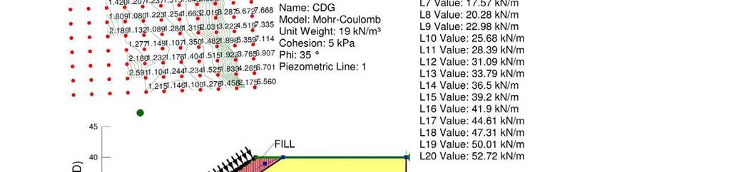
99 - 99 -
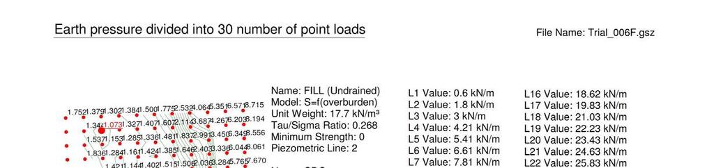
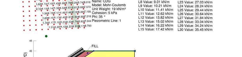
100
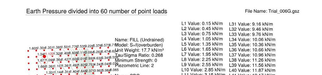
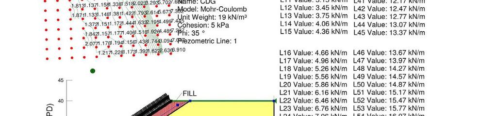
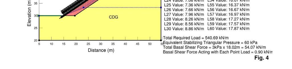
101
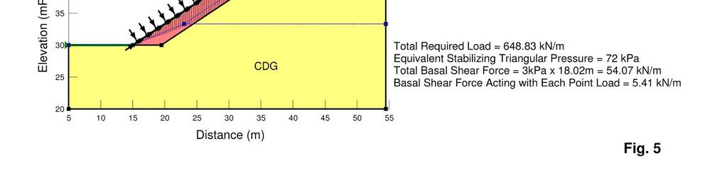
102
103 103
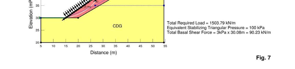
104 104
105 105

106 106 B.3 Slope Stability Analyses of Case of 60 Point Load Assumption with Grid and Radius Slip Surface

107 107 B.4 The Use of Bi-linear Slip Surfaces to Delineate the Non-liquefiable Zone
NPTEL Course. GROUND IMPROVEMENT Factors affecting the behaviour and performance of reinforced soil
 Lecture 27 NPTEL Course GROUND IMPROVEMENT Factors affecting the behaviour and performance of reinforced soil Prof. G L Sivakumar Babu Department of Civil Engineering Indian Institute of Science Bangalore
Geoguide 6 The New Guide to Reinforced Fill Structure and Slope Design in Hong Kong
 Geoguide 6 The New Guide to Reinforced Fill Structure and Slope Design in Hong Kong Geotechnical Engineering Office Civil Engineering Department The Government of the Hong Kong Special Administrative Region
Static Response of Reinforced Soil Retaining Walls with Modular Block Facing
 Static Response of Reinforced Soil Retaining Walls with Modular Block Facing Morteza Sabet 1, Amir M. Halabian 2, Kazem Barkhordari 3 1 Graduate Student, Department of Civil Engineering, Yazd University
Finite Element Analysis of Flexible Anchored Sheet Pile Walls: Effect of Mode of Construction and Dewatering Naveen Kumar 1, Arindam Dey 2*
 Golden Jubilee Conference of the IGS Bangalore Chapter, Geo-Innovations, 30-31 October 2014 Finite Element Analysis of Flexible Anchored Sheet Pile Walls: Effect of Mode of Construction and Dewatering
Performance of Reinforced Earth Retaining Wall with Fly Ash under Static and Dynamic Loading
 Performance of Reinforced Earth Retaining Wall with Fly Ash under Static and Dynamic Loading 1 Umesh Kumar N, 2 Padmashree M. Kalliamni 1 Geotechnical Engineer, 2 Assistant professor, 1 Civil Engineering
COURSE ON COMPUTATIONAL GEOTECHNICS A Geotechnical Design Tool. Faculty of Civil Engineering UiTM, Malaysia
 COURSE ON COMPUTATIONAL GEOTECHNICS A Geotechnical Design Tool Faculty of Civil Engineering, Malaysia Name : COURSE CONTENTS Use of Plaxis Getting Started Exercise 1: Elastic analysis of drained footing
Evaluation of negative skin friction on sheet pile walls at the Rio Grande dry dock, Brazil
 Geotechnical Aspects of Underground Construction in Soft Ground Viggiani (ed) 2012 Taylor & Francis Group, London, ISBN 978-0-415-68367-8 Evaluation of negative skin friction on sheet pile walls at the
Analysis of Buried Arch Structures; Performance Versus Prediction
 Analysis of Buried Arch Structures; Performance Versus Prediction D.A. Jenkins: Reinforced Earth Pty Ltd, Somersby, NSW, Australia Synopsis: The Reinforced Earth Group introduced the TechSpan arch system
Comparison of geotechnic softwares - Geo FEM, Plaxis, Z-Soil
 Comparison of geotechnic softwares - Geo FEM, Plaxis, Z-Soil Comparison du logiciel géotechnique Geo FEM, Plaxis, Z-Soil J. Pruška CTU in Prague FCE Department of Geotechnics, Prague, Czech Republic, Pruska@fsv.cvut.cz
Stability of a Mechanically Stabilized Earth Wall
 Stability of a Mechanically Stabilized Earth Wall GEO-SLOPE International Ltd. www.geo-slope.com 1400, 633-6th Ave SW, Calgary, AB, Canada T2P 2Y5 Main: +1 403 269 2002 Fax: +1 403 266 4851 Introduction
Geotechnical Analysis of Stepped Gravity Walls
 Geotechnical Analysis of Stepped Gravity Walls Baleshwar Singh 1 * and Birjukumar Mistri 2 1 Associate Professor, Civil Engineering Department, IIT Guwahati, India 2 Former Post-Graduate Student, Civil
EFFECT OF DEEP EXCAVATION SUPPORTED BY CONCRETE SOLIDER PILE WITH STEEL SHEET PILE LAGGING WALL ON ADJACENT EXISTING BUILDINGS
 EFFECT OF DEEP EXCAVATION SUPPORTED BY CONCRETE SOLIDER PILE WITH STEEL SHEET PILE LAGGING WALL ON ADJACENT EXISTING BUILDINGS Mostafa Abdou 1 *, Ahamed Rushedy Towfeek 2, Waleed Hassan 3 1 prof. Dr.,
Eurocode design using SLOPE/W
 Eurocode design using SLOPE/W GEO-SLOPE International Ltd. www.geo-slope.com 1400, 633-6th Ave SW, Calgary, AB, Canada T2P 2Y5 Main: +1 403 269 2002 Fax: +1 403 266 4851 Introduction SLOPE/W can be used
Earthquake Design of Flexible Soil Retaining Structures
 Earthquake Design of Flexible Soil Retaining Structures J.H. Wood John Wood Consulting, Lower Hutt 207 NZSEE Conference ABSTRACT: Many soil retaining wall structures are restrained from outward sliding
PRESTRESSED CONCRETE STRUCTURES. Amlan K. Sengupta, PhD PE Department of Civil Engineering Indian Institute of Technology Madras
 PRESTRESSED CONCRETE STRUCTURES Amlan K. Sengupta, PhD PE Department of Civil Engineering Indian Institute of Technology Madras Module 5: Analysis and Design for Shear and Torsion Lecture-23: Analysis
Pile foundations Introduction
 Engineering manual No. 12 Updated: 06/2018 Pile foundations Introduction Program: Pile, Pile CPT, Pile Group The objective of this engineering manual is to explain the practical use of programs for the
Numerical Analysis of the Durability of Retaining Wall with Anchor
 Numerical Analysis of the Durability of Retaining Wall with Anchor Qingyu Meng 1, 2, Chao Li 1, 2, Hongbo Zhang 1, 2, Xin Li 1, 2 1. School of Civil Engineering, Shandong University, Jinan, 250061, China
Coupled Stress-Seepage Numerical Design of Pressure Tunnels
 IAHR-HK Student Research Forum, November 17, 2012 Coupled Stress-Seepage Numerical Design of Pressure Tunnels Afis Olumide BUSARI, Prof. C.W. LI Department of Civil and Environmental Engineering, the Hong
The design of soil nailed structures to AS4678
 The design of soil nailed structures to AS4678 Chris Bridges Technical Principal - Geotechnics chris.bridges@smec.com 7 December 2016 1 Presentation Layout Introduction Soil Nailing in AS4678 Design Process
Design and analysis of deep beams, plates and other discontinuity regions BJÖRN ENGSTRÖM. q l (SLS) d ef. T SLS A ef. Tie = reinforced concrete Aef
 d ef. T SLS A ef. Tie = reinforced concrete Aef") q l (SLS) d ef T SLS A ef Tie = reinforced concrete Aef Design and analysis of deep beams, plates and other discontinuity regions BJÖRN ENGSTRÖM Department of Civil and Environmental Engineering Division
q l (SLS) d ef T SLS A ef Tie = reinforced concrete Aef Design and analysis of deep beams, plates and other discontinuity regions BJÖRN ENGSTRÖM Department of Civil and Environmental Engineering Division
Question Paper Code : 11410
 Reg. No. : Question Paper Code : 11410 B.E./B.Tech. DEGREE EXAMINATION, APRIL/MAY 2011 Fourth Semester Mechanical Engineering ME 2254 STRENGTH OF MATERIALS (Common to Automobile Engineering and Production
SETTLEMENTS DUE TO TUNNEL CONSTRUCTION
 5 SETTLEMENTS DUE TO TUNNEL CONSTRUCTION In this tutorial the construction of a shield tunnel in medium soft soil and the influence on a pile foundation is considered. A shield tunnel is constructed by
AVOIDING EXCESSIVE DISPLACEMENTS: A NEW DESIGN APPROACH FOR RETAINING WALLS
 International Conference on Structural and Foundation Failures August 2-4, 4, Singapore AVOIDING EXCESSIVE DISPLACEMENTS: A NEW DESIGN APPROACH FOR RETAINING WALLS A. S. Osman and M.D. Bolton Department
CHAPTER 2. Design Formulae for Bending
 CHAPTER 2 Design Formulae for Bending Learning Objectives Appreciate the stress-strain properties of concrete and steel for R.C. design Appreciate the derivation of the design formulae for bending Apply
Modelling of Piled Raft Foundation on Soft Clay
 Modelling of Piled Raft Foundation on Soft Clay Mohamed A.Baqi Mahmoud 1 and Hussien Elarabi 2 1 Department of Civil Engineering, Faculty of Engineering, University of Khartoum 2 Building and Road Research
Design of a Beam Structure for Failure Prevention at Critical Loading Conditions
 International Academic Institute for Science and Technology International Academic Journal of Innovative Research Vol. 3, No. 10, 2016, pp. 32-44. ISSN 2454-390X International Academic Journal of Innovative
Skirted Spudcan Sheet Pile Wall Interaction during Jack- Up Rig Installation and Removal in a Harbour Area
 Skirted Spudcan Sheet Pile Wall Interaction during Jack- Up Rig Installation and Removal in a Harbour Area L. Kellezi GEO - Danish Geotechnical Institute 1 Maglebjergvej, DK 2800 Copenhagen, Denmark G.
A Review of Soil Nailing Design Approaches
 A Review of Soil Nailing Design Approaches S.N.L. Taib 1 Abstract A number of design manuals and recommendations; namely by the HA 68 [4] (U.K.), BS8006 [1] (U.K.), RDGC [7] (France) and FHWA [5] (USA)
Behaviour of Strip Footing on Geogrid Reinforced Slope subjected to Eccentric Load
 ISSN (Print): 2347-671 (An ISO 3297: 27 Certified Organization) Behaviour of Strip Footing on Geogrid Reinforced Slope subjected to Eccentric Load Dhiraj D. Patil 1, Sunil S. Pusadkar 2, Sanjay W. Thakare
This document is downloaded from DR-NTU, Nanyang Technological University Library, Singapore.
 This document is downloaded from DR-NTU, Nanyang Technological University Library, Singapore. Title Three-dimensional finite element analysis of braced excavation systems Author(s) Winata, Berlina Margaretha.
BEARING CAPACITY IMPROVEMENT USING MICROPILES A CASE STUDY
 BEARING CAPACITY IMPROVEMENT USING MICROPILES A CASE STUDY G.L. Sivakumar Babu 1, B. R.Srinivasa Murthy 2, D.S. N. Murthy 3, M.S. Nataraj 4 ABSTRACT Micropiles have been used effectively in many applications
NON-LINEAR ANALYSIS OF BURIED ARCH STRUCTURES
 NON-LINEAR ANALYSIS OF BURIED ARCH STRUCTURES D.A. Jenkins Reinforced Earth Pty Ltd, Hornsby, NSW, Australia SUMMARY Groupe TAI introduced the TechSpan arch system in 1986. Since then over 5 buried precast
3 Dimensional Structural Modelling of Segmental Tunnel Lining Using Finite Element Software
 3 Dimensional Structural Modelling of Segmental Tunnel Lining Using Finite Element Software ABSTRACT R. Mahajan (rmahajan@pb.com.au) Parsons Brinckerhoff, Sydney Closed-face shielded TBM driven tunnels
Ground Improvement Using Steel Reinforcing Strips
 SAICE Geotechnical Division: Seminar on Ground Improvement Johannesburg, South Africa 8 & 9 October, 2001 Ground Improvement Using Steel Reinforcing Strips ACS Smith Reinforced Earth (Pty) Ltd, Johannesburg,
Nonlinear Models of Reinforced and Post-tensioned Concrete Beams
 111 Nonlinear Models of Reinforced and Post-tensioned Concrete Beams ABSTRACT P. Fanning Lecturer, Department of Civil Engineering, University College Dublin Earlsfort Terrace, Dublin 2, Ireland. Email:
LIMIT EQUILIBRIUM AND CONTINUUM MECHANICS-BASED NUMERICAL METHODS FOR ANALYZING STABILITY OF MSE WALLS
 LIMIT EQUILIBRIUM AND CONTINUUM MECHANICS-BASED NUMERICAL METHODS FOR ANALYZING STABILITY OF MSE WALLS Jie Han 1 (Member, ASCE) and Dov Leshchinsky 2 (Member, ASCE) ABSTRACT Limit equilibrium (LE) methods
Code No: R Set No. 1
 Code No: R059210303 Set No. 1 II B.Tech I Semester Regular Examinations, November 2006 MECHANICS OF SOLIDS ( Common to Mechanical Engineering, Mechatronics, Metallurgy & Material Technology, Production
Analysis of the stability of sheet pile walls using Discontinuity Layout Optimization
 Analysis of the stability of sheet pile walls using Discontinuity Layout Optimization S. D. Clarke, C. C. Smith & M. Gilbert The University of Sheffield, UK ABSTRACT: In this paper it is demonstrated that
Chapter 7. Finite Elements Model and Results
 Chapter 7 Finite Elements Model and Results 7.1 Introduction In this chapter, a three dimensional model was presented. The analytical model was developed by using the finite elements method to simulate
Estimation of Lateral Earth Pressure on Cantilever Sheet Pile using Flat Dilatometer Test (DMT) Data: Numerical Study
 Data: Numerical Study") Estimation of Lateral Earth Pressure on Cantilever Sheet Pile using Flat Dilatometer Test (DMT) Data: Numerical Study Kousik Deb Indian Institute of Technology Kharagpur, Kharagpur, India. E-mail: kousik@civil.iitkgp.ernet.in
Estimation of Lateral Earth Pressure on Cantilever Sheet Pile using Flat Dilatometer Test (DMT) Data: Numerical Study Kousik Deb Indian Institute of Technology Kharagpur, Kharagpur, India. E-mail: kousik@civil.iitkgp.ernet.in
Verification of a multi-anchored wall
 Engineering manual No. 7 Updated: 04/2018 Verification of a multi-anchored wall Program: File: Sheeting check Demo_manual_07.gp2 In this chapter, we will show you how to design and verify a multi-anchored
Modelling issues for numerical analysis of deep excavations
 Modelling issues for numerical analysis of deep excavations Helmut F. Schweiger Computational Geotechnics Group, Institute for Soil Mechanics und Foundation Engineering Graz University of Technology, Austria
 VALLIAMMAI ENGINEERING COLLEGE DEPARTMENT OF MECHANICAL ENGINEERING QUESTION BANK CE 6306 - STRENGTH OF MATERIALS UNIT I STRESS STRAIN DEFORMATION OF SOLIDS PART- A (2 Marks) 1. What is Hooke s Law? 2.
GUSSET PLATES IN RAILROAD TRUSS BRIDGES FINITE ELEMENT ANALYSIS AND COMPARISON WITH WHITMORE TESTING
 GUSSET PLATES IN RAILROAD TRUSS BRIDGES FINITE ELEMENT ANALYSIS AND COMPARISON WITH WHITMORE TESTING Walid S. Najjar, Ph.D., P.E. 1, Frank DeOrtentiis, P.E. WSP SELLS 555 Pleasantville Road, Briarcliff
Integral Bridges and the. Modeling of Soil-Structure Interaction
 Integral Bridges and the Click to edit Master title style Modeling of Soil-Structure Interaction Julian Moses, Principal Engineer, LUSAS Introduction 2 Introduction 3 Introduction 4 About soil-structure
BS EN :2004 EN :2004 (E)
") Contents List 1. General 1.1 Scope 1.1.1 Scope of Eurocode 2 1.1.2 Scope of Part 1-1 of Eurocode 2 1.2 Normative references 1.2.1 General reference standards 1.2.2 Other reference standards 1.3 Assumptions
Contents List 1. General 1.1 Scope 1.1.1 Scope of Eurocode 2 1.1.2 Scope of Part 1-1 of Eurocode 2 1.2 Normative references 1.2.1 General reference standards 1.2.2 Other reference standards 1.3 Assumptions
Increased plastic strains in containment steel liners due to concrete cracking and discontinuities in the containment structure
 Increased plastic strains in containment steel liners due to concrete cracking and discontinuities in the containment structure Patrick Anderson 1) and Ola Jovall 2) 1) Division of Structural Engineering,
Effect of Seismic Reinforcement of Sheet Pile Quay Wall Using Ground Anchor
 Effect of Seismic Reinforcement of Sheet Pile Quay Wall Using Ground Anchor M. Yoshida & M. Mitou Penta-Ocean Construction Co., Ltd., Japan O. Kiyomiya Waseda University, Japan S. Tashiro TOA Corporation,
APPENDIX B ABC STRUCTURES DESIGN GUIDE
 APPENDIX B ABC STRUCTURES DESIGN GUIDE The Cohos Evamy Partners TABLE OF CONTENTS Page No. DISCLAIMER... I 1. STRUCTURAL DESIGN GUIDELINES... 1 2. GENERAL REQUIREMENTS (FIGURE B.2, STEP 1)... 1 3. GENERAL
Numerical Modeling of Slab-On-Grade Foundations
 Numerical Modeling of Slab-On-Grade Foundations M. D. Fredlund 1, J. R. Stianson 2, D. G. Fredlund 3, H. Vu 4, and R. C. Thode 5 1 SoilVision Systems Ltd., 2109 McKinnon Ave S., Saskatoon, SK S7J 1N3;
UNIT-1 RETAINING WALLS
 UNIT-1 RETAINING WALLS PART-A 1. Describe about Retaining wall. 2. Define gravity retaining walls. BT-1 3. Classify the types of retaining walls. 4. Explain cantilever retaining wall? 5. Describe about
Modelling of a pile row in a 2D plane strain FE-analysis
 Numerical Methods in Geotechnical Engineering Hicks, Brinkgreve & Rohe (Eds) 2014 Taylor & Francis Group, London, 978-1-138-00146-6 Modelling of a pile row in a 2D plane strain FE-analysis J.J.M. Sluis,
Behavior of pile due to combined loading with lateral soil movement
 DOI 1.1186/s473-16-21-z ORIGINAL RESEARCH Open Access Behavior of pile due to combined loading with lateral soil movement B. Jegatheeswaran 1* and K. Muthukkumaran 2 *Correspondence: jegatheesb@gmail.com
In-plane testing of precast concrete wall panels with grouted sleeve
 In-plane testing of precast concrete wall panels with grouted sleeve P. Seifi, R.S. Henry & J.M. Ingham Department of Civil Engineering, University of Auckland, Auckland. 2017 NZSEE Conference ABSTRACT:
CHAPTER 5 2D FINITE ELEMENT MODELLING OF BURIED PIPE TESTS
 131 CHAPTER 5 2D FINITE ELEMENT MODELLING OF BURIED PIPE TESTS 5.1 INTRODUCTION Finite element method has been proved to be very useful tool in the analysis of buried structures. The method allows for
Lecture Retaining Wall Week 12
 Lecture Retaining Wall Week 12 Retaining walls which provide lateral support to earth fill embankment or any other form of material which they retain them in vertical position. These walls are also usually
Introduction to Structural Analysis TYPES OF STRUCTURES LOADS AND
 AND Introduction to Structural Analysis TYPES OF STRUCTURES LOADS INTRODUCTION What is the role of structural analysis in structural engineering projects? Structural engineering is the science and art
Application Note - Cantilever Stem Wall Analysis
 LS-G-AN4 Software: LimitState:GEO 2.0f Date: February 2011 Application Note - Cantilever Stem Wall Analysis 1 Introduction This note describes the typical steps followed in setting up and analysing a cantilever
NEW COMPOSITE CONSTRUCTION OF HYBRID BEAMS COMBINING STEEL INVERTED T-SECTION AND RC FLANGE
 NEW COMPOSITE CONSTRUCTION OF HYBRID BEAMS COMBINING STEEL INVERTED T-SECTION AND RC FLANGE Alex Remennikov 1, Marcus Roche 2 ABSTRACT: Steel and concrete composite beams are typically formed by shear
CHAPTER 11: PRESTRESSED CONCRETE
 CHAPTER 11: PRESTRESSED CONCRETE 11.1 GENERAL (1) This chapter gives general guidelines required for the design of prestressed concrete structures or members with CFRM tendons or CFRM tendons in conjunction
Geo-E2010 Advanced Soil Mechanics L Wojciech Sołowski. 19 March 2017
 Geo-E2010 Advanced Soil Mechanics L Wojciech Sołowski 19 March 2017 Slope stability: review Q: Shortcomings of undrained cohesion You wrote that the shortcoming is that the analysis is short term Well
DIVISION: EXTERIOR IMPROVEMENTS SECTION: RETAINING WALLS SECTION: SEGMENTAL RETAINING WALLS REPORT HOLDER:
 0 Most Widely Accepted and Trusted ICC-ES Evaluation Report ICC-ES 000 (800) 423-6587 (562) 699-0543 www.icc-es.org ESR-1784 Issued 02/2018 This report is subject to renewal 02/2019. DIVISION: 32 00 00
Passage under Lövstavägen at Bypass Stockholm From Design to Realization
 Passage under Lövstavägen at Bypass Stockholm From Design to Realization Roslin Mattias 1, Borio Luca 2 and Tomas Hellström 3 1 Swedish Transport Administration, Solna Strandväg 98, 171 54 Solna, mattias.roslin@trafikverket.se
BEHAVIOR OF INFILL MASONRY WALLS STRENGTHENED WITH FRP MATERIALS
 BEHAVIOR OF INFILL MASONRY WALLS STRENGTHENED WITH FRP MATERIALS D.S. Lunn 1,2, V. Hariharan 1, G. Lucier 1, S.H. Rizkalla 1, and Z. Smith 3 1 North Carolina State University, Constructed Facilities Laboratory,
NUMERICAL STUDY OF INVESTMENT BEHAVIOR CONTAINMENT WALLS (CASE STUDY STRUCTURAL GUARDIAN SYSTEMS PROJECT OF HABIB HOTEL OF MASHHAD)
") NUMERICAL STUDY OF INVESTMENT BEHAVIOR CONTAINMENT WALLS (CASE STUDY STRUCTURAL GUARDIAN SYSTEMS PROJECT OF HABIB HOTEL OF MASHHAD) Ali Eslam panahi 1, Soheil Ghareh 2 1 MSc in Civil Engineering - Geotechnical
NUMERICAL STUDY OF INVESTMENT BEHAVIOR CONTAINMENT WALLS (CASE STUDY STRUCTURAL GUARDIAN SYSTEMS PROJECT OF HABIB HOTEL OF MASHHAD) Ali Eslam panahi 1, Soheil Ghareh 2 1 MSc in Civil Engineering - Geotechnical
GEO-SLOPE International Ltd, Calgary, Alberta, Canada Tie-back Wall
 1 Introduction Tie-back Wall This example simulates the sequential construction of a sheet-pile shoring wall tied back with pre-stressed anchors. The purpose is to demonstrate the steps involved in modeling
Page 1 of 46 Exam 1. Exam 1 Past Exam Problems without Solutions NAME: Given Formulae: Law of Cosines: C. Law of Sines:
 NAME: EXAM 1 PAST PROBLEMS WITHOUT SOLUTIONS 100 points Tuesday, September 26, 2017, 7pm to 9:30 You are allowed to use a calculator and drawing equipment, only. Formulae provided 2.5 hour time limit This
Sabah Shawkat Cabinet of Structural Engineering 2017
 3.1-1 Continuous beams Every building, whether it is large or small, must have a structural system capable of carrying all kinds of loads - vertical, horizontal, temperature, etc. In principle, the entire
Ce 479 Reinforced Masonry Fall 2005
 INTRODUCTION TO STRUCTURAL DESIGN OF REINFORCED MASONRY In the preceding lecture on structural design of masonry, we have seen examples of unreinforced masonry bearing walls. In bearing walls, when the
Level 6 Graduate Diploma in Engineering Structural analysis
 9210-111 Level 6 Graduate Diploma in Engineering Structural analysis Sample Paper You should have the following for this examination one answer book non-programmable calculator pen, pencil, ruler, drawing
BROADENING OF HIGHWAYS AT CRITICAL SLOPE WATERWAY EMBANKMENTS USING VERTICAL PILES
 BROADENING OF HIGHWAYS AT CRITICAL SLOPE WATERWAY EMBANKMENTS USING VERTICAL PILES Assoc. Prof. Hisham Arafat Mahdi 1 Head of Structural Engineering & construction Management-FUE-Egypt ABSTRACT The main
Evaluation of Pseudo Static coefficient for Soil nailed walls on the basis of Seismic behavior levels
 Research Journal of Recent Sciences ISSN 2277-2502. Evaluation of Pseudo Static coefficient for Soil nailed walls on the basis of Seismic behavior levels Abstract Majid yazdandoust 1*, Ali komak panah
Analysis of Shear Wall Transfer Beam Structure LEI KA HOU
 Analysis of Shear Wall Transfer Beam Structure by LEI KA HOU Final Year Project report submitted in partial fulfillment of the requirement of the Degree of Bachelor of Science in Civil Engineering 2013-2014
Strut and tie. Betongbyggnad VBKN05
 Strut and tie Betongbyggnad VBKN05 Strut and Tie Design the deep beam (hög balk) in the figure. qd = 200 kn/m 3 m 3 m Strut and Tie Strut and Tie Describe the stresses in a concrete structure with a strut
Settlement Reduction Effect of Advanced Back-to-Back Reinforced Retaining Wall
 IJR International Journal of Railway Vol. 6, No. 3 / September 2013, pp. 107-111 The Korean Society for Railway Settlement Reduction Effect of Advanced Back-to-Back Reinforced Retaining Wall Koh, Taehoon,
Example of a modelling review Roof truss
 Example of a modelling review Roof truss Iain A MacLeod The Structure Figure gives an elevation and connection details for a roof truss. It is supported at each end on masonry walls. The trusses are at
Effects of Wall Embedded Length Ratio and Wall Thickness Ratio on Undrained Stability of Cantilever Piled Walls
 Engineering and Physical Sciences Effects of Wall Embedded Length Ratio and Wall Thickness Ratio on Undrained Stability of Cantilever Piled Walls Boonchai UKRITCHON *, Kant TEERAVONG and Suraparb KEAWSAWASVONG
Analytical study of a 2-span reinforced concrete beam strengthened with fibre reinforced polymer
 Analytical study of a 2-span reinforced concrete beam strengthened with fibre reinforced polymer Lander VASSEUR Civil Engineer Magnel Laboratory for Concrete Research, Ghent University, Ghent, BELGIUM
Geotechnical Engineering Software GEO5
 Geotechnical Engineering Software GEO5 GEO5 software suite is designed to solve various geotechnical problems. The easy -to -use suite consists of individual programs with an unified and user-friendly
5.4 Analysis for Torsion
 5.4 Analysis for Torsion This section covers the following topics. Stresses in an Uncracked Beam Crack Pattern Under Pure Torsion Components of Resistance for Pure Torsion Modes of Failure Effect of Prestressing
Analysis of a Road Embankment with Pond Ash in an Active Seismic Region
 Analysis of a Road Embankment with Pond Ash in an Active Seismic Region Balendra Mouli Marrapu & Ravi Sankar Jakka Indian Institute of Technology Roorkee, India (247667) SUMMARY: Huge quantities of ash
mortarless Design Manual Part 1 (AS 3600:2009) Section 1 Page 1 AS 3600:2009 PLAIN AND REINFORCED CONCRETE - CODE OF PRACTICE
 Section 1 Page 1 AS 3600:2009 PLAIN AND REINFORCED CONCRETE - CODE OF PRACTICE") SECTION 1. mortarless Design Manual Part 1 (AS 3600:2009) Section 1 Page 1 AS 3600:2009 PLAIN AND REINFORCED CONCRETE - CODE OF PRACTICE 1.1 Overview of AS 3600:2009 AS 3600:2009 is the latest Australian
SECTION 1. mortarless Design Manual Part 1 (AS 3600:2009) Section 1 Page 1 AS 3600:2009 PLAIN AND REINFORCED CONCRETE - CODE OF PRACTICE 1.1 Overview of AS 3600:2009 AS 3600:2009 is the latest Australian
THE OPTIMUM LOCATION OF REINFORCEMENT EMBANKMENT USING 3D PLAXIS SOFTWARE
 International Journal of Civil Engineering and Technology (IJCIET) Volume 7, Issue 5, September-October 1, pp. 91, Article ID: IJCIET_7_5_31 Available online at http://www.iaeme.com/ijciet/issues.asp?jtype=ijciet&vtype=7&itype=5
Active crack control in continuously reinforced concrete pavements (CRCP)
") fib_symposium_2017, 245, v2 (final): Active crack control in continuously reinforced co... 1 Active crack control in continuously reinforced concrete pavements (CRCP) Pieter De Winne 1, Hans De Backer
fib_symposium_2017, 245, v2 (final): Active crack control in continuously reinforced co... 1 Active crack control in continuously reinforced concrete pavements (CRCP) Pieter De Winne 1, Hans De Backer
A numerical simulation on the dynamic response of MSE wall with LWA backfill
 Numerical Methods in Geotechnical Engineering Hicks, Brinkgreve & Rohe (Eds) 2014 Taylor & Francis Group, London, 978-1-138-00146-6 A numerical simulation on the dynamic response of MSE wall with LWA backfill
Seismic Performance of Hollow-core Flooring: the Significance of Negative Bending Moments
 Seismic Performance of Hollow-core Flooring: the Significance of Negative Bending Moments L.J. Woods University of Canterbury and Holmes Consulting Group, New Zealand. R.C. Fenwick University of Canterbury,
Debonding Behavior of Skew FRP-Bonded Concrete Joints
 CICE 2010 - The 5th International Conference on FRP Composites in Civil Engineering September 27-29, 2010 Beijing, China Debonding Behavior of Skew FRP-Bonded Concrete Joints J. G. Dai (cejgdai@polyu.edu.hk)
Chapter 2: Mechanical Behavior of Materials
 Chapter : Mechanical Behavior of Materials Definition Mechanical behavior of a material relationship - its response (deformation) to an applied load or force Examples: strength, hardness, ductility, stiffness
Figure 1 Swing Span Supported by Center Pivot Pier and Two Rest Piers
 Abstract SEISMIC RETROFIT OF UNREINFORCED STONE MASONRY BRIDGE PIERS AND DISCRETE ELEMENT ANALYSIS Jaw-Nan (Joe) Wang 1 ; Michael J. Abrahams 2 The seismic behavior of unreinforced stone masonry structures
The use of flexible flaps in improving the settlement resistent behaviour of raft foundations
 SECM/15/144 The use of flexible flaps in improving the settlement resistent behaviour of raft foundations J.M.C.J.Jayasundara 1*, B.M.K.L.K.Basnayake 1 and K.G.H.C.N.senaviratne 1 1 University of Peradeniya,
OPTUM COMPUTATIONAL ENGINEERING FEATURES
 OPTUM COMPUTATIONAL ENGINEERING FEATURES Version 2016 OptumG2: Features K Krabbenhoft, AV Lymain, J Krabbenhoft (Editors) c Optum Computational Engineering 2016 www.optumce.com CONTENTS Contents 1 GENERAL
Finite Element Study Using FE Code (PLAXIS) on the Geotechnical Behavior of Shell Footings
 on the Geotechnical Behavior of Shell Footings") Journal of Computer Science 2 (1): 104-108, 2006 ISSN 1549-3636 Science Publications Finite Element Study Using FE Code (PLAXIS) on the Geotechnical Behavior of Shell Footings Bujang B.K. Huat and Thamer
Journal of Computer Science 2 (1): 104-108, 2006 ISSN 1549-3636 Science Publications Finite Element Study Using FE Code (PLAXIS) on the Geotechnical Behavior of Shell Footings Bujang B.K. Huat and Thamer
CIRCULAR TUBE COLUMNS IN HIGH STRENGTH STEEL Economical solutions for building frames
 EUROSTEEL 014, September 10-1, 014, Naples, Italy CIRCULAR TUBE COLUMNS IN HIGH STRENGTH STEEL Economical solutions for building frames Van-Long Hoang a, Jean-Pierre Jaspart a, Jean-François Demonceau
CHAPTER 10: GENERAL STRUCTURAL DETAILS
 CHAPTER 10: GENERAL STRUCTURAL DETAILS 10.1 GENERAL It shall be in accordance with JSCE Standard Specification (Design), 9.1, "steel" shall be taken to signify "steel or CFRM". 10.2 CONCRETE COVER (1)
Parametric Study on Geogrid-Reinforced Track Substructure
 IJR International Journal of Railway Vol. 6, No. 2 / June 2013, pp. 59-63 ISSN 1976-9067(Print) ISSN 2288-3010(Online) Parametric Study on Geogrid-Reinforced Track Substructure Jeongho Oh Abstract The
BEHAVIOUR OF REINFORCED CONCRETE STRUCTURES IN FIRE
 BEHAVIOUR OF REINFORCED CONCRETE STRUCTURES IN FIRE ZHAOHUI HUANG, IAN W. BURGESS and ROGER J. PLANK 3 ABSTRACT In the past two decades, a significant amount of research has been conducted into the performance
Comparison of One-way and Two-way slab behavior. One-way slabs carry load in one direction. Two-way slabs carry load in two directions.
 Two-way Slabs Comparison of One-way and Two-way slab behavior One-way slabs carry load in one direction. Two-way slabs carry load in two directions. Comparison of One-way and Two-way slab behavior One-way
Numerical Analysis of a Novel Piling Framed Retaining Wall System
 The 12 th International Conference of International Association for Computer Methods and Advances in Geomechanics (IACMAG) 1-6 October, 2008 Goa, India Numerical Analysis of a Novel Piling Framed Retaining
Long-term Stress of Simply Supported Steel-concrete Composite Beams
 The Open Construction and Building Technology Journal, 2011, 5, 1-7 1 Open Access Long-term Stress of Simply Supported Steel-concrete Composite Beams Min Ding 1,2, Xiugen Jiang 1, Zichen Lin 3 and Jinsan
Design of Soil Nailed Walls According to AS
 Design of Soil Nailed Walls According to AS4678-2002 Chris Bridges, SMEC, Brisbane, Queensland Keywords: soil nail, retaining wall, Australian Standards ABSTRACT The use of soil nails in the construction