June 2007
|
|
|
- Samantha Alexander
- 6 years ago
- Views:
Transcription

1 CONCRETE PIPE June
2 Agenda o Terminology o Manufacturing Methods o ASTM Specifications o Pipe Joints o Pipe Testing o Fittings o Manholes o Sizing o Flotation
3 Manufacturing Methods Wet Cast Dry Cast 3
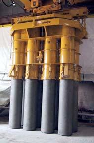
4 Manufacturing Methods Wet Cast- Uses a concrete mix that is wet relative to the mixes used in other processes. Usually contains a slump less than 4 inches and used for production of large diameter pipe. Dry Cast- Uses a concrete mix with zero slump. The method has several variations but all use low frequency-high amplitude vibration to distribute and densely compact dry mix in the form. 4

5 Two Methods of Dry Cast Manufacturing Vibratory Sources o o Internal Hydraulic External Pneumatic Electric Hydraulic 5

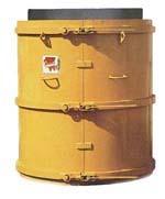
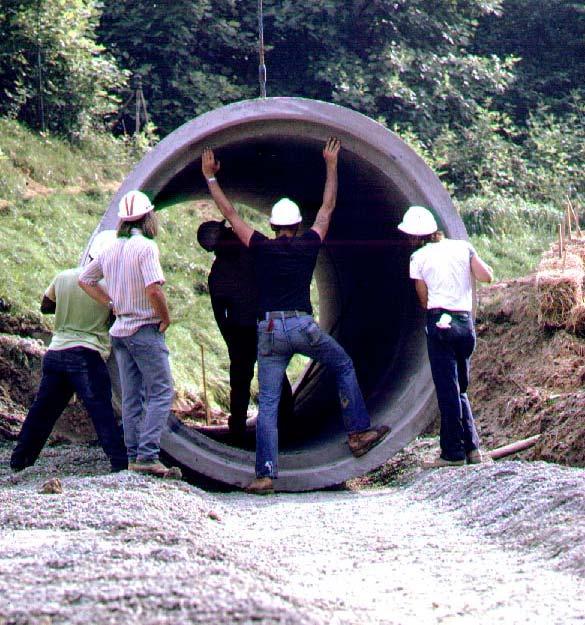
6 Dry Cast 84 x 16 6

7 Dry Cast Box Culvert 7
8 3 Types of ASTM Standards Manufacturing Testing Installation 8
9 Manufacturing Specifications o o o o o o o o C-14 Non-reinforced Concrete Pipe C-76 Reinforced Concrete Pipe C-361 Low Pressure RCP C-443 Rubber Gasket Joints for RCP C-478 Manholes C-506 Arch RCP C-507 Elliptical RCP C-1433 Precast Box Culverts Replaced C-789 & C-850 9
10 Pipe Design Considers Installation Note from ASTM C76: This specification is a manufacturing and purchase specification only, and does not include requirements for bedding, backfill, or the relationship between field load condition and the strength classification of pipe. However, experience has shown that the successful performance of this product depends upon the proper selection of the class of pipe, type of bedding and backfill, and care that installation conforms to the construction specifications. The owner of the reinforced concrete pipe specified herein is cautioned that he must correlate the field requirements with the class of pipe specified and provide inspection at the construction site. 10
11 Test Specifications o o o o o C-497 Test Methods for RCP & MH o o o 3 Edge Bearing Core & Cylinder Strength Hydrostatic Test C-924 Low Pressure Air Testing, up to 24 C-969 Infiltration/Exfiltration Test of Installed Concrete Pipe C-1214 Vacuum Testing of Installed Pipe C-1244 Vacuum Testing of Installed MH 11
12 Installation Specifications o C-1479 Installation of RCP Using Standard Installations o Companion Design Spec w/ ASCE 15 o Section 27 of AASHTO LRFD Bridge Construction Specifications 12
13 Joints The links that make the system whole Additional Info in the Concrete Design Manual - click here June
14 Bell & Spigot or Tongue & Groove What s the Deal? Female end of pipe (bell, groove) portion of the end of the pipe, regardless of shape, which overlaps a portion of the end of the adjoining pipe Male end of pipe (spigot, tongue) - portion of the end of the pipe, regardless of shape, which is overlapped by portion of the end of the adjoining pipe 14
15 Arch & Elliptical Shapes 15
16 Define the Service Requirements Soil Tight Silt Tight Watertight gravity Watertight pressure 16
17 Soil Tight/ Silt Tight Storm drains and culverts only! Intended to preclude soil / silt transfer through joint Non-precision joint Mastic sealant Preformed butyl sealant Mortar Joint Fabric External Wrap ASTM C990 17
18 Soil Tight Joint 18
19 Soil Tight Joint with Fabric 19

20 Pushing Box Joint Home 20
21 Soil Tight/Silt Tight Joint with External Wrap ASTM C877 21

22 Soil/ Silt Tight Joint 22

23 Soil Tight Joint 23
24 Watertight Gravity* Precision Joint O-Ring gasket Profile gasket ASTM C443 ASTM C1628 * Tested to zero leakage in the manufacturing plant 24
25 Watertight - Gravity Joint Confined Gasket - O-Ring or Profile 25

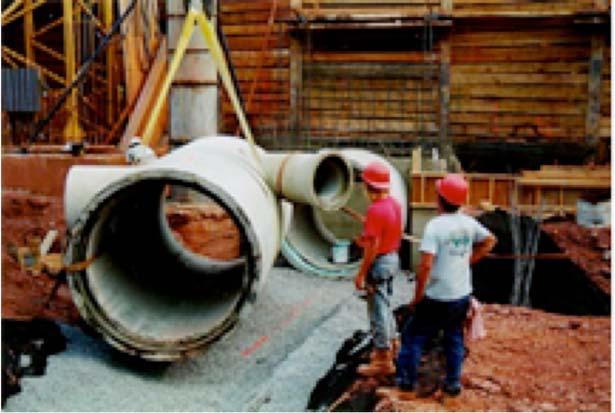
26 Watertight - Gravity Joint 26
27 Watertight - Gravity Joint Offset Spigot - Profile Gasket 27

28 Watertight - Gravity Joint 28
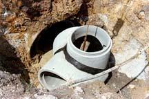
29 Watertight - Pressure Precision Joint O-Ring gasket ASTM C361 29

30 Steel Joint Ring Pipe 30
31 Gasket materials Polyisoprene - standard use Chloroprene - moderate hydrocarbon resistance Nitrile / Viton - high hydrocarbon resistance o-ring gasket profile gasket 31

32 Joint Testing Ensures joint integrity after installation ASTM C497 32
33 Fittings Bevels / Radius, not always available Bends Tees NOTE: Check supplier for availability Additional Info in the Concrete Design Manual - click here 33
34 Bevels / Radius Pipe or Boxes Additional Info. Click Here 34
35 35


36 Bends Tees/Wyes Reducers/ Increasers Adapters Fittings 36

37 Fittings Bends Tees/Wyes Reducers/Increasers Adapters 37
38 38
39 Manholes Testing Sizing Flotation Connectors & Joint Sealants Depth Round or Square Additional Design Data Click Here Additional Info in the Concrete Design Manual - click here 39

40 Vacuum Testing Manholes ASTM C

41 Vacuum Testing Manholes 41

42 Manhole Flotation Additional Design Data Click Here 42
43 43
44 Manhole Sizing Flexibility Handling Weight 44
45 SIZING MANHOLES MULTIPLE HOLES AT SAME ELEVATION MH Dia. M, in/deg M= Circumference/360º M x Angle = Y Y - Pipe #1 Opening/2 - Pipe #2 Opening/2 = a A = Distance between the two openings Minimum a is 6 for Dia. MH and 8 for *4 Dia. MH C L 90 a C L Example: Pipe #1 = 36 RCP B 6:00 Pipe #2 = 36 RCP B 3:00 Angle = 90º Try 72 Dia. MH Y = x 90º = A = /2-53/2 = 3.55 < 6 ; too small Therefore, try 84 Dia. MH: Y = x 90º = A = /2-51/2 = > 8 ; OK Pipe #1 45
46 Pipe Dia., in. Hole chord Dim., in. 48 Ø Hole Size (Arc) per MH Diameter, in. 60 Ø 70 Ø 84 Ø 96 Ø / /59 5./55 51/ / /57 70/75 63/66 60/63 59/ /64 75/79 70/ / Note: Where two dimensions are shown, I.e. 48/50, the first one is for B Wall pipe and the second one is for C Wall pipe. Use the Arc length for calculations. 46
47 Concrete Pipe Design Basics


48 Fact : Buried Pipe Must Perform Two Critical Functions Buried Pipe Conduit Structure


49 Structure Conduit Concrete Pipe


50 Traffic Load Earth Load Final Backfill Loads Haunching Initial Backfill Bedding Foundation Supporting Strength Rigid Pipe

51 Unstable Foundation! 51
52 How do we define the strength of concrete pipe?


53 Class D-Load? Wall Thickness? 3-Edge Bearing
54 Wall Thickness & Reinforcement A-Wall Wall thickness in inches = Diameter in feet 24 Pipe = 2 Wall B-Wall Wall thickness in inches =Diameter in feet Pipe = 3 Wall 24 Pipe = 3.75 Wall C-Wall Wall thickness in inches =Diameter in feet

55 Three-Edge-Bearing Applied Load ASTM C76, C506, C507 ASTM C497 Test Specimen Support
 to produce 0.01 crack, 12 long D ULT = load (lbs/ft. span/ft. length) to cause structural failure")
56 D-Load Supporting strength of a pipe loaded under three-edge bearing test conditions, expressed in pounds per linear foot per foot of inside diameter or horizontal span when tested according to ASTM C497. D 0.01 = load (lbs/ft. span/ft. length) to produce 0.01 crack, 12 long D ULT = load (lbs/ft. span/ft. length) to cause structural failure
57 Gravity Pipe Classes AASHTO M170 ASTM C76 Class I II III IV V D-Load D-Load Ult
58 60 ASTM C-76 Class IV 8 D 0.01 = 2000 D ULT = 3000 Total Load Required: D 0.01 = (60/12)(8)(2000) = 80,000 lbs. D ULT = (60/12)(8)(3000) = 120,000 lbs. AASHTO M170 ASTM C76 Class I II D-Load D-Load Ult III IV V
59 80,000 lbs. 60 Cl IV RCP


60 Loads on Pipe Earth Live Construction Other Additional Design Data Click Here
61 Selection of Pipe Strength D load.01 = Where: W E B FE B FL + W L D-Load.01 = Required structural capacity, lb./ft. 2 W E = Earth load, lb./ft. W L = Live load, lb./ft. D = Pipe diameter, ft. B FE = Earth Load Bedding Factor B FL = Live Load Bedding Factor FS = Factor of safety Additional Info in the Concrete Design Manual - click here X FS D


62 Gravity Pipe Classes AASHTO M170 ASTM C76 Class I II III IV V D-Load D-Load Ult

63 Prescriptive Specification Cook Book Spec

64 Bedding Factor depends on type and quality of installation Standard Installations Click here
65 Who Is Responsible for Bedding Factor? Engineer via specification, inspection and testing Contractor via installation means and methods Inspector via inspection and testing Additional Info in the Concrete Design Manual - click here
66 How do we design concrete pipe?


67 System Design Structure Durability Joint


68 System Design Structure
69 Design Basics Installation Methodology & Earth Load Determination Additional Info in the Concrete Design Manual - click here
70 Pipe Installation Methods Trench Positive projection embankment Negative projection embankment Jacked, bored, or tunneled Additional Info in the Concrete Design Manual - click here

71 Installation Methods Trench Negative Projecting Positive Projecting Tunnel
72 Positive Projecting Embankment Final Grade Existing Grade
73 Positive Projecting Embankment
74 Existing and Final Grade Trench
75 Trench Undisturbed Soil Undisturbed Soil
76 Negative Projecting Embankment Final Grade Existing Grade
77 Negative Projecting Embankment
78 Trenchless
79 Installation (embedment) Types or Classes Additional Info in the Concrete Design Manual - click here
80 Do /3 Di Do /6 Min. Do Do Min. Standard Installations Foundation Middle Bedding Haunch Outer Bedding Lower Side H
81 Standard Installations - ASTM & AASHTO Installation Type Bedding Thickness Haunch & Outer Bedding Lower Side Type I D O /24 minimum, not 95% Category I 90% Category I less than 3 in. (75 mm). 95% Category II If rock foundation, use 100% Category III D O /12 minimum, not less than 6 in. (150 mm). Type 2 D O /24 minimum, not 90% Category I 85% Category I less than 3 in. (75 mm). 95% Category II 90% Category II If rock foundation, use 95% Category III D O /12 minimum, not less than 6 in. (150 mm). Type 3 D O /24 minimum, not 85% Category I 85% Category I less than 3 in. (75 mm). 90% Category II 90% Category II If rock foundation, use 95% Category II 95% Category III D O /12 minimum, not less than 6 in. (150 mm). Type 4 No bedding required No compaction required, No compaction required, except if rock except if Category III, except if Category III, foundation, use D O /12 use 85% use 85% minimum, not less than 6 in. (150 mm).
82 Cost Standard Installations Total Cost Pipe Cost Construction Cost Type 1 Type 2 Type 3 Type 4 Standard Installation


83 Options for Finding Required Pipe Strength Plug & chug - blue book Fill height tables Computer software - PipePac 2000
84 Steps for Determining the Required Pipe Strength 1 - Select the method of installation (trench, embankment, etc.) 2 - Determine the earth load (Installation Type: 1-4) 3 - Determine the live load 4 - Determine the bedding factor (installation type: 1 4) 5 - Calculate the required D-Load 6 - Specify the class 84
85 D load.01 = W E B FE B FL + W L X FS D
86 Step 1 Determine the Method of Installation Additional Info in the Concrete Design Manual - click here
87 Step 2 Determine Earth Load Additional Info in the Concrete Design Manual - click here
88
89 W E = VAF x PL VAF Vertical Arching Factor Type 1 VAF = 1.35 Type 2 VAF = 1.40 Type 3 VAF = 1.40 Type 4 VAF = 1.45 PL - Prism Load, the weight of the column of earth cover over the pipe outside diameter 89
90 Step 3 Determine the Live Load Additional Info in the Concrete Design Manual - click here
91 Live Load Sources Highway loads Railroad loads Aircraft loads Construction loads Other
92
93 Step 4 Determine the Bedding Factor Additional Info in the Concrete Design Manual - click here
94 Bedding Factors, Embankment Conditions Pipe Standard Installation Diameter Type 1 Type 2 Type 3 Type 4 12 in in in in in Notes: 1. For pipe diameters other than listed in Illustration 4.21, embankment condition factors, B fe can be obtained by interpolation. 2. Bedding Factors are based on the soils being placed with the minimum compaction specified in Illustration 4.4 for each standard installation. 94
95 Step 5 Calculate the Required D-Load Additional Info in the Concrete Design Manual - click here

96 Selection of Pipe Strength D load.01 = Where: W E B FE B FL + W L D-Load.01 = Required structural capacity, lb./ft. 2 W E = Earth load, lb./ft. W L = Live load, lb./ft. D = Pipe diameter, ft. B FE = Earth Load Bedding Factor B FL = Live Load Bedding Factor FS = Factor of safety Additional Info in the Concrete Design Manual - click here X FS D
97 Step 6 Select the Class
98 Gravity Pipe Classes ASTM C76 Class D-Load.01 D-Load ult. I II III IV V
99 Fill Height Tables
100 Installation Type Bedding Thickness Haunch & Outer Beddding Lower Side Type 1 D o /24 minimum, not less 95% Category I 90% Category I than 3 in. (75 mm). If 95% Category II rock foundation, use 100% Category III D o /12 minimum, not less than 6 in. (150 mm).
101
102
103
104 Installation Type Bedding Thickness Haunch & Outer Bedding Lower Side Type 4 No bedding required No compaction required, No compaction required, except if rock except if Category III, use except if Category III, use Foundation, use 85% 85% D o /12 minimum, not less than 6 in. (150mm)
105

106 Computer Program PipePac 2000
107 Congratulations! You are almost finished. Please see remaining slides for the exam questions and submittal form to receive your PDH. PDH for this course: 2.0 Non Member Fee: $99.00 Member & Non Industry Engineer Fee: no charge June
108 Instructions for Submitting Exam Print out the exam submittal form and test. Complete the exam by circling the answers on the form. Complete submittal form. Mail your exam, submittal form and payment (if applicable) to: American Concrete Pipe Association 8445 Freeport Parkway, Suite 350 Irving, TX Attn: Professional Membership Online Exam Your exam will be graded by the ACPA and the results provided to you within 60 days of receipt. 108
109 Required Contact Information: RCP 101 Exam Submittal Form Name: Date: Street Address: Mailing Address: City: State: Zip Code: Telephone: Fax: Website: www Certification of ethical completion: I certify that I read the course presentation, understood the learning objective, and completed the exam questions to the best of my ability. Additionally, the contact information provided above is true and accurate Signature: Date: PDH Value: Your exam answers will be graded by The American Concrete Pipe Association. If you answer at least 75 percent of the questions correctly, you will receive a certificate of completion from The American Concrete Pipe Association within 60 days and will be awarded 2.0 professional development hour (equivalent to 0.2 continuing education unit in most states). Note: It is the responsibility of the licensee to determine if this method of continuing education meets his or her board(s) of registration s requirements. Instructions: Select one answer for each exam question and clearly circle the appropriate letter. 1) a b c d 5) a b c d 2) a b c d 6) a b c d 3) a b c d 7) a b c d 4) a b c d 8) a b c d Fee: $99.00 Payment Information Check Enclosed MasterCard VISA American Express Name on Card Card No. Expiration Date Signature * All credit card transactions are processed in U.S. dollars and are subject to the current exchange rates. American Concrete Pipe Association 8445 Freeport Parkway, Suite 350, Irving, TX (972) Fax (972)
110 Exam Which two methods are used to manufacture concrete pipe? Wet cast and wet-out Packerhead and Hydrostatic Packerhead and dry cast Internal and external hydraulic Soil Tight Joints are used for what two design types? Culverts and Storm Drains Manholes and Culverts Storm Drains and Manholes Sanitary Sewer and Manholes The supporting strength of a pipe loaded under three-edge bearing test conditions is the same as in the installed condition. True False Which installation method results in the highest soil load on the pipe? Negative projecting Positive projecting Trench Tunnel 110
111 Exam (cont.) Name the two different types of Watertight joints. Soil Tight and Water Tight Tongue & Groove and Bell & Spigot O-ring and Profile Pressure and O-ring What is the test used to determine D-load in a pipe? There is no test Three-Edge Bearing Test Joint Shear Test Hydrostatic Test What two critical functions must buried concrete pipe perform? Barrier and Structure Framework and System Structure and Conduit Channel and Aqueduct The earth load, live load and bedding factor are all considered in determining what? D-Load Hydraulic Capacity Diameter of Pipe Type of Joint 111
112 Thank you for participating in ACPA s online training. Please send us an at info@concrete-pipe.org if you would like to suggest a training topic to be added in the future. In the subject line include online training topic
CONCRETE PIPE JOINTS, YOUR BEST CHOICE
 CONCRETE PIPE JOINTS, YOUR BEST CHOICE www.concretepipe.org FREQUENTLY ASKED QUESTIONS Q. Are joints covered by National Standards? A. Yes. There are ASTM and AASHTO standards for concrete products joints.
Technical Overview of Concrete Pipe Design, Installation, Inspection and Construction Pitfalls
 Technical Overview of Concrete Pipe Design, Installation, Inspection and Construction Pitfalls Rinker Materials-Concrete Pipe Division Sarah Matin, P.E. BS Civil Engineering University of Central Florida
Concrete Pipe Joints Your Best Choice
 Frequently Asked Questions Q. Are joints covered by National Standards? A. Yes. There are ASTM and AASHTO standards for concrete products joints. The various standards are discussed in this publication.
Draft. Not Yet Approved SECTION 10.1 GENERAL SCOPE DEFINITIONS
 SECTION 10.1 GENERAL 10.1.1 SCOPE This part of the Manual covers the structural design and installation of reinforced concrete pipe for railway culverts. Pipe geometry may be circular, arch, or elliptical.
Wastewater Capital Projects Management Standard Construction Specification
 CITY AND COUNTY OF DENVER ENGINEERING DIVISION Wastewater Capital Projects Management Standard Construction Specification 10.1 PRECAST CONCRETE PIPE 10.1.1 General This section covers material requirements,
ITEM 460 REINFORCED CONCRETE PIPE Description. This Item shall govern for the furnishing of reinforced concrete pipe.
 AFTER MARCH 1, 2012 ITEM 460 REINFORCED CONCRETE PIPE 460.1 Description. This Item shall govern for the furnishing of reinforced concrete pipe. 460.2 Materials. A. Except as modified herein, materials,
SECTION 39 - MANHOLES TABLE OF CONTENTS 39-1 GENERAL PRECAST CONCRETE MANHOLES
 Section SECTION 39 - MANHOLES TABLE OF CONTENTS 39-1 GENERAL... 39-1 39-2 PRECAST CONCRETE MANHOLES... 39-1 39-2.01 Precast Concrete Storm Drain Manholes... 39-1 39-3 SADDLE MANHOLES... 39-2 39-3.01 Saddle
SECTION STORM SEWER PIPE
 SECTION 4200 - STORM SEWER PIPE 4200.1 SCOPE: This section covers the requirements for all labor, equipment and materials for the installation of storm sewers pipes. Trenching guidelines are provided in
CHAPTER 5 SUPPLEMENTAL DATA
 CHAPTER 5 SUPPLEMENTAL DATA CIRCULAR CONCRETE PIPE Illustration 5.2 includes tables of dimensions and approximate weights of most frequently used types of circular concrete pipe. Weights are based on concrete
TABLE OF CONTENTS
 DIVISION 33: SEWER AND SEPTIC SYSTEMS 33 3633 UTILITY SEPTIC TANK DRAINAGE FIELD TABLE OF CONTENTS 33 0000-1 SECTION 33 3633-- UTILITY SEPTIC TANK DRAINAGE FIELD PART 1 - GENERAL 1.1 SUMMARY A. Includes
ITEM D-701 PIPE FOR STORM DRAINS AND CULVERTS
 ITEM D-701 PIPE FOR STORM DRAINS AND CULVERTS 701-1 DESCRIPTION 701-1.1 This item shall consist of the construction of pipe culverts, and storm drains, removal of existing storm pipes, connections to existing
Design Data 9. Standard Installations and Bedding Factors for the Indirect Design Method
 Design Data 9 Standard Installations and Bedding Factors for the Indirect Design Method Background The classic theory of earth loads on buried concrete pipe published, in 1930 by A. Marston, was developed
50.20 Drainage Structure Design
 50.20 Drainage Structure Design All drainage structures, with the exception of bridges, culvert bridges and, in some cases, culverts, shall be designed for HS20-44 loading. Refer to Section 50.22 for design
PERMANENT PAVEMENT REPAIR NO SCALE
 SAWCUT EXISTING PAVEMENT 2" BITUMINOUS CONCRETE SURFACE COURSE, CLASS 2 (MIN) CLEAN EDGE PRIOR TO PAVING AND PAINT WITH LIQUID BITUMEN. INSTALL SEALANT OVER JOINT UPON COMPLETION 2" BITUMINOUS CONCRETE
SECTION 39 - MANHOLES TABLE OF CONTENTS
 Section SECTION 39 - MANHOLES TABLE OF CONTENTS Page 39-1 GENERAL... 39.1 39-2 CONCRETE MANHOLES... 39.1 39-2.01 NOT USED... 39.1 39-2.02 Concrete Storm Drain Manholes... 39.1 39-3 SADDLE SEWER MANHOLES...
Section 403. DRAINAGE STRUCTURES
 403.01 Section 403. DRAINAGE STRUCTURES 403.01. Description. This work consists of adjusting, constructing, or temporarily lowering drainage structures and cleaning existing drainage structures and leads
PIPE CULVERTS. Construct pipe culverts, beveled ends, pipe aprons, and associated appurtenances.
 PIPE CULVERTS PART 1 - GENERAL 1.01 SECTION INCLUDES A. Pipe Culverts B. Pipe Aprons and Beveled Ends C. Footings for Concrete Pipe Aprons D. Pipe Apron Guards 1.02 DESCRIPTION OF WORK Construct pipe culverts,
SECTION SANITARY SEWER SYSTEM
 SECTION 02731 SANITARY SEWER SYSTEM PART 1 GENERAL 1.01 SUMMARY A. Section Includes: Sanitary sewer system including necessary accessories indicated on drawings and specified in this section. Contractor
Section Storm Sewers STORM SEWERS PART 1 - GENERAL 1.01 SECTION INCLUDES. A. Storm Sewers. B. Abandonment of Storm Sewers
 STORM SEWERS PART 1 - GENERAL 1.01 SECTION INCLUDES A. Storm Sewers B. Abandonment of Storm Sewers 1.02 DESCRIPTION OF WORK A. Construct storm sewers. B. Abandon storm sewers. 1.03 SUBMITTALS Comply with
SPECIAL SPECIFICATION 4425 Thermoplastic Pipe
 2004 Specifications CSJ 0264-07-028 SPECIAL SPECIFICATION 4425 Thermoplastic Pipe 1. Description. Furnish and install thermoplastic pipe for constructing thermoplastic pipe culverts or thermoplastic storm
Drainage structure refers to manholes, catch basins, leaching basins, inlets and drop inlets. Drainage structures are designated as follows.
 403.01 Section 403. DRAINAGE STRUCTURES 403.01 Description. Adjust, construct, or temporarily lower drainage structures. Clean existing drainage structures and leads as directed by the Engineer. Drainage
Design Data 6. Loads and Supporting Strengths Elliptical and Arch Pipe. Values of B d
 Design Data 6 Loads and Supporting Strengths Elliptical and Arch Pipe The hydraulic and structural characteristics of elliptical and arch shapes offer advantages, under certain conditions, over the circular
SECTION STORM SEWER COLLECTION SYSTEM
 SECTION 02722 STORM SEWER COLLECTION SYSTEM PART 1 GENERAL 1.01 SUMMARY A. This section addresses the installation of storm sewer collection mains and includes the acceptable products, materials, and construction
B. Fiberglass for construction in back lot easements placed on cast-in-place base.
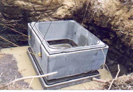
 Section 02083 PART 1 G E N E R A L 1.01 SECTION INCLUDES A. Fiberglass manholes for unpaved areas placed on top of a precast base to form a manhole. B. Fiberglass for construction in back lot easements
CHAPTER 4 LOADS AND SUPPORTING STRENGTHS
 CHAPTER 4 LOADS AND SUPPORTING STRENGTHS The design procedure for the selection of pipe strength requires: I. Determination of Earth Load 2. Determination of Live Load 3. Selection of Bedding 4. Determination
ADDENDUM January 2018 Updates for the 13 th Edition NPCA QC Manual QCM-001, Rev. 0,
 ADDENDUM January 2018 Updates for the 13 th Edition NPCA QC Manual QCM-001, Rev. 0, 1-1-18 The NPCA Quality Assurance Committee has again raised the bar on quality for NPCA Plant Certification. The format
Testing. Test drainage products according to the applicable AASHTO or ASTM specification, except as otherwise noted.
 909.01 Section 909. DRAINAGE PRODUCTS 909.01 General Requirements. If only the size and class are specified for a culvert or sewer, use the pipe materials as shown in Table 401-1 and 402-1 respectively.
STANDARD CONSTRUCTION DETAILS SANITARY SEWER REVISED MARCH 2018 DEPARTMENT OF ENGINEERING
 STANDARD CONSTRUCTION DETAILS REVISED MARCH 2018 GENERAL NOTES EMBEDMENT DETAILS EMBEDMENT DETAILS TWO-WAY CLEANOUT - EXISTING LATERAL TWO-WAY CLEANOUT - NEW CONSTRUCTION TYPICAL SEWER HOUSE SERVICE CONNECTION
San Antonio Water System Standard Specifications for Construction ITEM NO. 848 SANITARY SEWERS
 ITEM NO. 848 SANITARY SEWERS 848.1 DESCRIPTION: This item shall govern the furnishing, installation and jointing of sanitary sewer pipe of the size and type specified by the project's plans and specifications.
This type of masonry shall consist of brick laid in full beds of cement mortar.
 SECTION 11.0 DRAINAGE STRUCTURES 11.01 Scope of Work This item shall consist of installation and construction of storm drainage pipes, culverts, basins, headwalls, manholes, junction boxes, head ditches,
1 Revised: 2019 Edition
 STORM SEWERS PART 1 - GENERAL 1.01 SECTION INCLUDES A. Storm Sewers B. Abandonment of Storm Sewers 1.02 DESCRIPTION OF WORK A. Construct storm sewers. B. Abandon storm sewers. 1.03 SUBMITTALS Comply with
SECTION 300 STORM SEWER TABLE OF CONTENTS
 SECTION 300 STORM SEWER TABLE OF CONTENTS Starts on Page 300 GENERAL... 2 301 MATERIALS... 2 302 CONSTRUCTION PROCEDURES... 5 303 TESTING... 5 304 ABANDONMENT OF EXISTING STORM SEWER FACILITIES... 6 305
SPECIAL SPECIFICATION 4653 Polypropylene Pipe
 2004 Specifications CSJ 2158-01-013, Etc. SPECIAL SPECIFICATION 4653 Polypropylene Pipe 1. Description. Furnish and install polypropylene pipe for constructing polypropylene pipe culverts or polypropylene
PASSAIC COUNTY TECHNICAL INSTITUTE CCA 1422 NEW S.T.E.M. BUILDING 2017
 SECTION 02630 - STORM DRAINAGE PART 1 - GENERAL 1.1 RELATED DOCUMENTS A. Drawings and general provisions of the Contract, including General and Supplementary Conditions and Division 01 Specification Sections,
207 TEMPORARY SEDIMENT AND EROSION CONTROLS
 2013 Construction and Material Specifications Hydraulics and Environmental Summary Ron Trivisonno, Office of Construction Administration 207 TEMPORARY SEDIMENT AND EROSION CONTROLS This item has been removed
CONCRETE PIPE USE MANUAL
 CONCRETE PIPE USE MANUAL Prepared By The Illinois Concrete Pipe Association Table of Contents SUBJECT PAGE I. Introduction 1. I. Storm Sewers & Culverts Introduction 2 Specifications Circular Pipe (ASTM
16. Design of Pipeline Structures.
 16. Design of Pipeline Structures. a. General. 1) The following guidelines are for the design of structures for water and sewer pipelines including structural concrete and miscellaneous metals design.
SECTION TRENCHING
 SECTION 31 23 17 TRENCHING PART 1 GENERAL 1.1 SUMMARY A. Section Includes: 1. Excavating trenches for utilities and utility structures. 2. Bedding. 3. Backfilling and compacting to subgrade elevations.
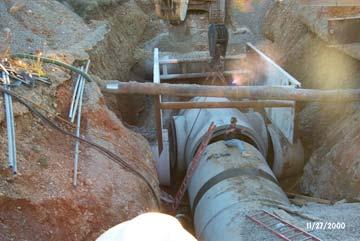
Design Data 4. Jacking Concrete Pipe
 Design Data 4 Jacking Concrete Pipe FOREWORD Jacking or tunneling concrete pipe is an increasingly important construction method for installing concrete pipelines without interrupting commerce, or disturbing
SECTION UTILITY MANHOLES AND STRUCTURES
 SECTION 33 05 14 UTILITY MANHOLES AND STRUCTURES PART 1 GENERAL 1.1 SUMMARY A. Section Includes: 1. Precast reinforced concrete manholes and structures with tongue-and-groove joints with masonry transition
7-0 SANITARY SEWER SYSTEMS
 ADS, Inc. Drainage Handbook Sanitary Sewer Systems 7-1 7-0 SANITARY SEWER SYSTEMS TABLE OF CONTENTS 7-1 Overview of Sanitary Sewer Systems... 7-2 7-2 Sanitary Sewer Projects... 7-2 Preliminary Investigation...
QUALITY CONTROL PROGRAM FOR PRECAST CONCRETE PRODUCTS SECTION 1902 QUALITY CONTROL PROGRAM FOR PRECAST CONCRETE PRODUCTS
 SECTION 1902 QUALITY CONTROL PROGRAM FOR PRECAST CONCRETE PRODUCTS 1902.1 DESCRIPTION This specification covers precast concrete pipe, end sections, inlets, manholes, boxes, and related concrete accessories.
SECTION STORM DRAINAGE SYSTEM Excavating, Backfilling, and Compaction for Utilities Cast-in-place Concrete.
 SECTION 02720 STORM DRAINAGE SYSTEM PART 1 GENERAL 1.01 SUMMARY A. Related Sections: 1. 02221 - Excavating, Backfilling, and Compaction for Utilities. 2. 03300 - Cast-in-place Concrete. 1.02 REFERENCES
SECTION FACILITY SANITARY SEWERS
 SECTION 22 13 13 FACILITY SANITARY SEWERS PART 1 - GENERAL 1.1 RELATED DOCUMENTS A. Drawings and general provisions of the Contract, including General and Supplementary Conditions and Division 01 Specification
FOX METRO WATER RECLAMATION DISTRICT MANHOLE / SEWER PIPE MATERIALS AND INSTALLATION SPECIFICATIONS MATERIALS 1. PIPE & FITTINGS
 FOX METRO WATER RECLAMATION DISTRICT MANHOLE / SEWER PIPE MATERIALS AND INSTALLATION SPECIFICATIONS MATERIALS 1. PIPE & FITTINGS Rev: 3/26/18 Pipe and fittings used in sanitary sewer construction shall
SECTION MANHOLES AND STRUCTURES. A. Section Includes: 1. Manholes for water, storm drain and sanitary sewer systems.
 SECTION 33 05 13 MANHOLES AND STRUCTURES PART 1 GENERAL 1.1 SUMMARY A. Section Includes: 1. Manholes for water, storm drain and sanitary sewer systems. B. Related Sections: 1. Section 03 20 00 - Concrete
Hydraulic Updates. History of 603/604
 Ohio Department of Transportation John R. Kasich, Governor Jerry Wray, Director Hydraulic Updates SS 802 Constructing and Inspecting Pipe Culverts, Sewers, Drains and Drainage Structures AND SS 902 Conduit
SANITARY SEWERS. B. Construct or relocate building sanitary sewer services, stubs, and connections.
 SANITARY SEWERS PART 1 - GENERAL 1.01 SECTION INCLUDES A. Sanitary Sewer Gravity Mains B. Sanitary Sewer Force Mains C. Sanitary Sewer Services 1.02 DESCRIPTION OF WORK A. Construct sanitary sewer gravity
MANHOLES, VAULTS AND CATCH BASINS SECTION A. Section Soil and Aggregate Materials. C. Section Storm Drainage Systems
 SECTION 02607-1 1.0 GENERAL 1.1 SCOPE: A. This section covers the work necessary for the construction of sanitary and storm system manholes, catch basins, and miscellaneous concrete structures complete.
Summary of the 2011 Changes
 The following is a list of amendments to the Residential Site Improvement s, N.J.A.C. 5:21, adopted in 2011. The Notice of Adoption of these changes appeared in the New Jersey Register on May 16, 2011.
SECTION XXXX POLYMER CONCRETE PUMP STATIONS
 SECTION XXXX POLYMER CONCRETE PUMP STATIONS PART 1 GENERAL 1.1 SUMMARY A. This specification shall govern for the furnishing of all work necessary for installation of polymer concrete pump stations to
SECTION D2 MANHOLES AND CATCH BASINS GENERAL MATERIALS
 SECTION D2 MANHOLES AND CATCH BASINS GENERAL This section covers the installation of new manholes, catch basins, drop inlets, drywall structures and the installation of hoods in existing catch basins.
SECTION SANITARY UTILITY SEWERAGE PIPING
 SECTION 33 31 00 SANITARY UTILITY SEWERAGE PIPING PART 1 GENERAL 1.1 SUMMARY A. Section Includes: 1. Sanitary sewer pipe and fittings. 2. Underground pipe markers. 3. Connection to existing manholes. 4.
SECTION 601 PIPE CULVERTS GENERAL DESCRIPTION
 601 SECTION 601 PIPE CULVERTS GENERAL DESCRIPTION 601.01.01 GENERAL A. This section includes general requirements that are applicable to all types of culvert pipes regardless of the material or culvert
QUALITY CONTROL PROGRAM FOR PRECAST CONCRETE PRODUCTS SECTION 1902 QUALITY CONTROL PROGRAM FOR PRECAST CONCRETE PRODUCTS
 SECTION 1902 QUALITY CONTROL PROGRAM FOR PRECAST CONCRETE PRODUCTS 1902.1 DESCRIPTION This specification covers precast concrete pipe, end sections, inlets, manholes, boxes, and related concrete accessories.
ITEM 432 TUNNEL CONSTRUCTION
 AFTER MARCH 1, 2012 ITEM 432 TUNNEL CONSTRUCTION 432.1 Description. This Item shall govern for tunnel lines under railroads, state highways, and concrete paved streets or other obstructions indicated.
***************************************************************************************************************
 02720 STORM DRAINAGE SYSTEM *************************************************************************************************************** SPECIFIER: CSI MasterFormat 2004 number 33 40 00. ***************************************************************************************************************
SANITARY SEWERS. B. Construct or relocate building sanitary sewer services, stubs, and connections.
 SANITARY SEWERS PART 1 - GENERAL 1.01 SECTION INCLUDES A. Sanitary Sewer Gravity Mains B. Sanitary Sewer Force Mains C. Sanitary Sewer Services 1.02 DESCRIPTION OF WORK A. Construct sanitary sewer gravity
ONE PIPE LENGTH MAX (REFER TO 1/4"/FT SLOPE (MIN) 5'-0" (MIN) OR 4" LATERAL NOTE #1) INCREASER RIGHT-OF-WAY/ 4"x6" REFER TO TYPICAL EXCAVATION,
 5'-0 (MIN) OR 4 LATERAL NOTE #1) INCREASER RIGHT-OF-WAY/ 4x6 REFER TO TYPICAL EXCAVATION,") VENT CAP (MUSHROOM TYPE) SOLID CAP EXIST GRADE MIN BUILDING REFER TO NOTE #4 MIN CONCRETE SIDEWALK CURB OR EDGE OF SIDEWALK STREET CLEANOUT (REFER TO NOTE #3) VENT PIPE 4" PVC 6" PVC CLEANOUT CONCRETE
VENT CAP (MUSHROOM TYPE) SOLID CAP EXIST GRADE MIN BUILDING REFER TO NOTE #4 MIN CONCRETE SIDEWALK CURB OR EDGE OF SIDEWALK STREET CLEANOUT (REFER TO NOTE #3) VENT PIPE 4" PVC 6" PVC CLEANOUT CONCRETE
SECTION PRECAST CONCRETE MANHOLES
 SECTION 02601 PRECAST CONCRETE MANHOLES PART 1 GENERAL 1.1 The work specified in this section shall include the furnishing, hauling, and placing of all precast manholes shown on the drawings and as specified
Table of Contents. Section Structures for Sanitary and Storm Sewers Section Includes Description of Work 1. 1.
 SUDAS Standard Specifications Division 6 - Structures for Sanitary and Storm Sewers Table of Contents Section 6010 - Structures for Sanitary and Storm Sewers Page No. Part 1 - General 1.01 Section Includes
San Antonio Water System Standard Specifications for Construction ITEM NO. 853 SANITARY SEWER GLASS-FIBER REINFORCED POLYESTER (FRP) MANHOLES
 MANHOLES") ITEM NO. 853 SANITARY SEWER GLASS-FIBER REINFORCED POLYESTER (FRP) MANHOLES 853.1 DESCRIPTION: This item shall govern the construction of FRP sanitary sewer complete in place and the material therein,
ITEM NO. 853 SANITARY SEWER GLASS-FIBER REINFORCED POLYESTER (FRP) MANHOLES 853.1 DESCRIPTION: This item shall govern the construction of FRP sanitary sewer complete in place and the material therein,
MagnumStone Specifications Gravity
 MagnumStone Specifications Gravity SPECIFICATION FOR MAGNUMSTONE GRAVITY MECHANICALLY STABILIZED EARTH SYSTEM PART 1: GENERAL.01Description The work consists of supplying and installing all aspects of
Special Provision for LRFD Pipe Culvert Burial Tables
 All Regional Engineers Omer M. Osman, P.E. Special Provision for LRFD Pipe Culvert Burial Tables January 9, 2015 This special provision was developed by the Bureau of Bridges and Structures as a result
CHAPTER 200 STORM SEWER CONSTRUCTION STANDARDS
 CHAPTER 200 STORM SEWER CONSTRUCTION STANDARDS Storm Sewer System: 1. Detention/retention of stormwater runoff shall be provided in accordance with the requirements of the DuPage County Countywide Stormwater
SECTION STORM DRAIN
 PART 1 - GENERAL 1-01 SECTION INCLUDED A. Furnishing and installing storm drainage facilities, including pipe, cleanout, manhole structures and inlet structures. 1-02 RELATED SECTIONS A. Division 00 Contract
San Antonio Water System Specifications for Construction ITEM NO. 853 SANITARY SEWER GLASS-FIBER REINFORCED POLYESTER (FRP) MANHOLES
 MANHOLES") ITEM NO. 853 SANITARY SEWER GLASS-FIBER REINFORCED POLYESTER (FRP) MANHOLES 853.1 DESCRIPTION: This item shall govern the construction of FRP sanitary sewer manholes, complete in place and the materials
ITEM NO. 853 SANITARY SEWER GLASS-FIBER REINFORCED POLYESTER (FRP) MANHOLES 853.1 DESCRIPTION: This item shall govern the construction of FRP sanitary sewer manholes, complete in place and the materials
NOTE: 1) PRIOR TO BEGINNING WORK TRANSFER RIM ELEV. FROM MH K1 TO A TEMPORARY BENCH MARK FOR USE AS CONTROL DURING CONSTRUCTION. 2) CONTRACTOR TO INST
 PRIOR TO BEGINNING WORK TRANSFER RIM ELEV. FROM MH K1 TO A TEMPORARY BENCH MARK FOR USE AS CONTROL DURING CONSTRUCTION. 2) CONTRACTOR TO INST") NOTE: 1) PRIOR TO BEGINNING WORK TRANSFER RIM ELEV. FROM MH K1 TO A TEMPORARY BENCH MARK FOR USE AS CONTROL DURING CONSTRUCTION. 2) CONTRACTOR TO INSTALL MANHOLE LIDS FLUSH WITH EXISTING GROUND SURFACE.
NOTE: 1) PRIOR TO BEGINNING WORK TRANSFER RIM ELEV. FROM MH K1 TO A TEMPORARY BENCH MARK FOR USE AS CONTROL DURING CONSTRUCTION. 2) CONTRACTOR TO INSTALL MANHOLE LIDS FLUSH WITH EXISTING GROUND SURFACE.
ITEM 464 REINFORCED CONCRETE PIPE
 ITEM 464 REINFORCED CONCRETE PIPE 464.1. Description. This Item shall govern for furnishing and installing all concrete pipe and materials and for constructing precast concrete pipe culverts or precast
KANSAS DEPARTMENT OF TRANSPORTATION SPECIAL PROVISION TO THE STANDARD SPECIFICATIONS, EDITION OF 1990
 Sheet 1 of 7 KANSAS DEPARTMENT OF TRANSPORTATION SPECIAL PROVISION TO THE STANDARD SPECIFICATIONS, EDITION OF 1990 NOTE: This special provision is generally written in the imperative mood. The subject,
SECTION STORM DRAINAGE
 SECTION 02720 STORM DRAINAGE PART 1 - GENERAL 1.01 WORK INCLUDED A. Trenching and other excavation. B. Ground water control. C. Pipe bedding. D. Installation of storm drains and appurtenances. E. Installation
The Weak Links in the Wastewater Collection System: Manholes and Access Devices. Antonio V Almeida, PE CMOM 2014 Austin Texas August 19, 2014
 The Weak Links in the Wastewater Collection System: Manholes and Access Devices Antonio V Almeida, PE CMOM 2014 Austin Texas August 19, 2014 Agenda Manhole Design The Manhole Paradigm past, present & future
1993 SPECIFICATIONS CSJ SPECIAL SPECIFICATION ITEM 4110 CONCRETE ENCASED DUCT BANK
 1993 SPECIFICATIONS CSJ 581-1-95 SPECIAL SPECIFICATION ITEM 4110 CONCRETE ENCASED DUCT BANK 1. DESCRIPTION. This Item shall govern for the furnishing and installation of all materials and equipment for
1.02 RELATED WORK: Refer to the following sections for related work:
 SECTION 5100 - SANITARY SEWER MAIN PART 1 - GENERAL 1.01 SCOPE: This Section covers installation of sanitary sewer mains and services. Topics include permits and fees, record drawings, pipe materials,
SECTION WASTE WATER DRAINAGE SYSTEM Excavating, Backfilling, and Compaction for Utilities Cast-in-Place Concrete.
 SECTION 02735 WASTE WATER DRAINAGE SYSTEM PART 1 GENERAL 1.01 SUMMARY A. Related Sections: 1. 02221 - Excavating, Backfilling, and Compaction for Utilities. 2. 03300 - Cast-in-Place Concrete. 1.02 REFERENCES
GWINNETT COUNTY STORM SEWER PIPE STANDARDS
 1.0 Standard Specifications GWINNETT COUNTY STORM SEWER PIPE STANDARDS 1.1 Unless otherwise specifically set forth herein or in the Gwinnett County Standard Drawings, all of the materials, methods of the
NORTH HARRIS COUNTY REGIONAL WATER AUTHORITY CAST-IN-PLACE. Section CAST-IN-PLACE CONCRETE MANHOLES
 PART 1 GENERAL 1.01 SUMMARY This Section includes: Section 02081 CAST-IN-PLACE A. Cast-in-place concrete manholes for sanitary sewers and storm sewers, including box sewers. B. Pile-supported concrete
ITEM NO. 853 SANITARY SEWER GLASS-FIBER REINFORCED POLYESTER (FRP) MANHOLES
 MANHOLES") ITEM NO. 853 SANITARY SEWER GLASS-FIBER REINFORCED POLYESTER (FRP) MANHOLES 853.1 DESCRIPTION: This item shall govern the construction of FRP sanitary sewer complete in place and the material therein,
ITEM NO. 853 SANITARY SEWER GLASS-FIBER REINFORCED POLYESTER (FRP) MANHOLES 853.1 DESCRIPTION: This item shall govern the construction of FRP sanitary sewer complete in place and the material therein,
STANDARD SPECIFICATION FOR OIL GRIT SEPARATOR (OGS) STORMWATER QUALITY TREAMENT DEVICE
 STORMWATER QUALITY TREAMENT DEVICE") STANDARD SPECIFICATION FOR OIL GRIT SEPARATOR (OGS) STORMWATER QUALITY TREAMENT DEVICE PART 1 GENERAL 1.1 WORK INCLUDED This section specifies requirements for constructing underground stormwater treatment
STANDARD SPECIFICATION FOR OIL GRIT SEPARATOR (OGS) STORMWATER QUALITY TREAMENT DEVICE PART 1 GENERAL 1.1 WORK INCLUDED This section specifies requirements for constructing underground stormwater treatment
Section 401. PIPE CULVERTS
 401.02 Section 401. PIPE CULVERTS 401.01. Description. This work consists of constructing pipe culverts of the size and class required, including excavation and backfill. 401.02. Materials. Provide materials
SRPE AASHTO Specifications.
 SRPE AASHTO Specifications July 19, 2013 Steel Ribbed HDPE = SRHDPE = SRPE Now has AASHTO Design and Construction Specifications for SRPE. 2 But wait there is more AASHTO Bridge Design Specs - Section
NTPEP Evaluation of Spray Applied Non-Structural and Structural Pipe Liners for Storm Water Conveyance
 Work Plan for NTPEP Evaluation of Spray Applied Non-Structural and Structural Pipe Liners for Storm Water Conveyance AASHTO Designation: [SAL] (2018) American Association of State Highway and Transportation
SECTION 1 TERMS, DEFINITIONS, ABBREVIATIONS, UNITS OF MEASURE, AND SYMBOLS 1-3 ABBREVIATIONS Common Usage.
 SECTION 1 TERMS, DEFINITIONS, ABBREVIATIONS, UNITS OF MEASURE, AND SYMBOLS 1-3 ABBREVIATIONS. 1-3.2 Common Usage. Abbreviations Word or Words PAV.Pressure Aging Vessel PCC..Portland Cement Concrete PE.Polyethylene
PRESS-SEAL CORPORATION
 PREFORMED BUTYL JOINT SEALANT Where To Use Sanitary Manhole Joints Stormwater Manhole Joints Irrigation and Drainage Systems Box Culverts Elliptical/Arch Pipe Architectural Foundations Underground Utility
INSTALLATION OF CONCRETE PRESSURE PIPE BY MICROTUNNELING OR JACKING
 12 ACPPA TECHNICAL SERIES INSTALLATION OF CONCRETE PRESSURE PIPE BY MICROTUNNELING OR JACKING AWWA C300 OR C302 PIPE Jacking, including microtunneling, allows installation of pipe in deep covers, under
SPECIAL SPECIFICATION 5925 Polyvinyl Cloride (PVC) Sewer Pipe and Fittings
 Sewer Pipe and Fittings") 1993 Specifications CSJ 0144-01-060 SPECIAL SPECIFICATION 5925 Polyvinyl Cloride (PVC) Sewer Pipe and Fittings 1. General. (1) Scope. This Section includes the furnishing, installation, and subsequent
1993 Specifications CSJ 0144-01-060 SPECIAL SPECIFICATION 5925 Polyvinyl Cloride (PVC) Sewer Pipe and Fittings 1. General. (1) Scope. This Section includes the furnishing, installation, and subsequent
PART II. - SPECIFICATIONS AND DESIGN STANDARDS TO CITY OF HEWITT, TEXAS SUBDIVISION ORDINANCE FOR PUBLIC WORKS CONSTRUCTION [TEXT]
![PART II. - SPECIFICATIONS AND DESIGN STANDARDS TO CITY OF HEWITT, TEXAS SUBDIVISION ORDINANCE FOR PUBLIC WORKS CONSTRUCTION [TEXT]](/thumbs/80/81891816.jpg "PART II. - SPECIFICATIONS AND DESIGN STANDARDS TO CITY OF HEWITT, TEXAS SUBDIVISION ORDINANCE FOR PUBLIC WORKS CONSTRUCTION [TEXT]") PART II. - SPECIFICATIONS AND DESIGN STANDARDS TO CITY OF HEWITT, TEXAS SUBDIVISION ORDINANCE FOR PUBLIC WORKS CONSTRUCTION [TEXT] A. - General. B. - Streets. C. - Stormwater drainage system. D. - Water
PART II. - SPECIFICATIONS AND DESIGN STANDARDS TO CITY OF HEWITT, TEXAS SUBDIVISION ORDINANCE FOR PUBLIC WORKS CONSTRUCTION [TEXT] A. - General. B. - Streets. C. - Stormwater drainage system. D. - Water
ADDENDUM January 2018 Updates for the 13 th Edition NPCA QC Manual QCM-001, Rev. 0,
 ADDENDUM January 2018 Updates for the 13 th Edition NPCA QC Manual QCM-001, Rev. 0, 1-1-18 The NPCA Quality Assurance Committee has again raised the bar on quality for NPCA Plant Certification. The format
Note: All of the above referenced ASTM Standards can be found in 2008 Selected ASTM Standards on Concrete Pipe, Resource # Book
 American Concrete Pipe Association Professional Product Proficiency A Technical and Sales/Marketing Training Program ACPA Technical Series Module I: Basic RCP Course 6: Concrete Pipe - Product Standards
REGIONAL CONSTRUCTION STANDARDS
 REGIONAL CONSTRUCTION STANDARDS SIXTH EDITION Publication Update 6.5 (Full Committee Approved Proposed Revision 6.5 Storm Sewer Joint Wrap - Section 302 As Publication Update 6.5) March 27, 2018 Copyright
SECTION PIPE & PIPE FITTINGS PART 1 GENERAL
 SECTION 02610 PIPE & PIPE FITTINGS PART 1 GENERAL 1.01 DESCRIPTION A. This Section includes the material and bedding requirements for all pipe and pipe fittings for underground pressure and non-pressure
CITY OF SCHERTZ TEXAS ENGINEERING AND PUBLIC WORKS
 TEXAS STANDARD CONSTRUCTION NOTES DRWN. BY: DSGN. BY: KJW 1 of 2 *Place geotextile fabric as a permeable seperator to prevent mixing of coarse aggregate and underlying soil. (as needed). 1. GEOTEXTILE
VALLECITOS WATER DISTRICT SECTION PRECAST REINFORCED CONCRETE MANHOLES
 PART 1 GENERAL 1.1 DESCRIPTION A. This section includes materials, testing, and installation of precast concrete manholes, manhole bases, manhole frames, and covers. 1.2 RELATED WORK SPECIFIED ELSEWHERE
New Fulton State Hospital Energy Control Center and Services Building (ECC/SVC) Project Number: M
 Project Number: M") SECTION 334100 - STORM UTILITY DRAINAGE PIPING PART 1 -GENERAL 1.1 RELATED DOCUMENTS A. Drawings and general provisions of the Contract, including General and Supplementary Conditions and Division 01 Specification
SECTION 334100 - STORM UTILITY DRAINAGE PIPING PART 1 -GENERAL 1.1 RELATED DOCUMENTS A. Drawings and general provisions of the Contract, including General and Supplementary Conditions and Division 01 Specification
DEPARTMENT OF TRANSPORTATION STATE OF GEORGIA SPECIAL PROVISION. Section 550 Storm Drain Pipe, Pipe-Arch Culverts, and Side Drain Pipe
 Revised: October 25, 2007 Revised: June 11, 2010 DEPARTMENT OF TRANSPORTATION STATE OF GEORGIA SPECIAL PROVISION Section 550 Storm Drain Pipe, Pipe-Arch Culverts, and Side Drain Pipe Delete Section 550
ITEM NO SLIPLINING SANITARY SEWERS
 ITEM NO. 1100 SLIPLINING SANITARY SEWERS 1100.1 DESCRIPTION: Sliplining is accomplished by pulling or pushing liner pipe into existing sewers by use of mechanical or hydraulic equipment. Once in place,
VALLECITOS WATER DISTRICT SECTION POLYVINYL CHLORIDE (PVC) PRESSURE PIPE
 PRESSURE PIPE") PART 1 - GENERAL 1.1 DESCRIPTION A. This section designates the requirements for the manufacture and installation of polyvinyl chloride, abbreviated PVC, pressure pipe. 1.2 RELATED WORK SPECIFIED ELSEWHERE
PART 1 - GENERAL 1.1 DESCRIPTION A. This section designates the requirements for the manufacture and installation of polyvinyl chloride, abbreviated PVC, pressure pipe. 1.2 RELATED WORK SPECIFIED ELSEWHERE
PRESS-SEAL CORPORATION
 PREMIUM BUTYL JOINT SEALANT Where To Use Sanitary Manhole Joints Stormwater Manhole Joints Irrigation and Drainage Systems Box Culverts Elliptical/Arch Pipe Architectural Foundations Underground Utility
NORTHWESTERN UNIVERSITY PROJECT NAME JOB # ISSUED: 03/29/2017
 SECTION 33 3400 STORM UTILITY DRAINAGE PIPING PART 1 - GENERAL 1.1 RELATED DOCUMENTS A. Drawings and general provisions of the Contract, including General and Supplementary Conditions and Division 01 Specification
Table of Contents. Section Sanitary Sewers Section Includes Description of Work Submittals 1. 1.
 Table of Contents Section 00 - Sanitary Sewers Page No. Part - General.0 Section Includes.0 Description of Work.03 Submittals.0 Substitutions.05 Delivery, Storage, and Handling.06 Scheduling and Conflicts.07