CF50/100 KW TURBINE ACCESS ROAD, CRANE PLATFORM, CONCRETE, AND LIFTING SPECIFICATIONS C&F GREEN ENERGY REVISION PREPARED BY APPROVED BY DATE
|
|
|
- Victoria Horn
- 6 years ago
- Views:
Transcription

1 CF50/100 KW TURBINE ACCESS ROAD, CRANE PLATFORM, CONCRETE, AND LIFTING SPECIFICATIONS C&F GREEN ENERGY REVISION PREPARED BY APPROVED BY DATE 001 First Draft W Hession

2 Introduction This document has been designed as a guideline which describes the minimum requirements for access roads, crane platforms and turbine foundations for the CF 50 CF 100 KW Wind Turbine. This document is also designed to be included in contractual agreements as a supplementary document to specify such minimum requirements and any deviation hereto. This document is not sufficient in and of itself to construct Access Roads, Crane Pads, Pad Foundations and Hardstands and must be supplemented for each project and site before construction work commences in order to ensure the specifications and the final choice of crane and transport equipment are aligned with the site requirements. The exact design of Access Roads, Crane Pads, Pad Foundations and Hardstands must be agreed with C&F Green Energy in writing prior to start of construction. Recipient acknowledges that this document is provided for recipient s information only, and that any and all promise, commitments, or other representations by C&F green energy are contained exclusively in signed written contracts between recipient and C&F green energy, and not within this document.
3 Abbreviations and Definitions Access Road(s) BS Refers to a road, existing or purpose-built, which leads from any public road system to the Site Entrance. Refers to British Standards. Bearing Capacity Factor of Safety CBR Ratio of ultimate bearing capacity to allowable bearing capacity to be determined by a C& F engineer. Refers to the California Bearing Ratio. This is a test to determine the ratio between the pressure required to penetrate the soil at the site and a standardized soil of known properties. Crane Pad Roads Site Refers to a hardstand area in connection with the erection or service of a wind turbine. Refers to any Access and/or Site Roads. Refers to all areas where the permanent works are to be executed and to which turbines and all associated equipment and materials are to be delivered, and any other areas that may be specified in the contract as forming part of the Site. C&F Turbine Summary: Weight of CF turbine head 12 ton Length of blades for turbine 10m/12m Weight of two turbine masts/towers bottom section 9 ton/ top section 7 ton Length of each turbine mast/tower bottom section 13.5 m/ top section 13.5m Weight of turbine can 2 ton Dimensions of base foundation to be excavated by client 11m x 11m x 1.8m Dimensions of concrete foundation 9m x 9m x 1.4m Approximately 18 cubes for the sub-base concrete pour, mix of C30/37 Approximately 120 cubes for the main concrete pour, mix of C32/40 Concrete pump required for main concrete pour. Excavator bucket shall not be used during main concrete pour Independent concrete tester required to sample and test main concrete mix onsite

 Clients Geotechnical report confirming the")
4 Geotechnical Testing Each turbine excavation is required to have a geotechnical investigation carried out. The geotechnical report should incorporate the below points. Trial pit investigation (the trial pit investigation will establish if any additional testing is required) CBR or plate bearing tests on access road and crane hardstand PH and sulphate tests Groundwater monitoring standpipe (Geotechnical engineer to confirm) Clients Geotechnical report confirming the proposed site has adequate bearing capacity. The above photo is a typical trial pit investigation CBR test for access road carried out using a Land Rover


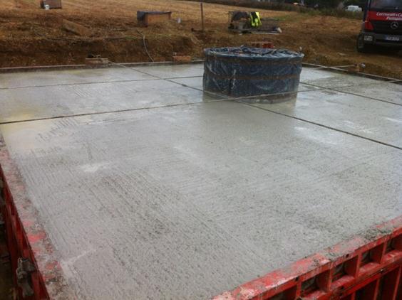
5 Plant required 3 ton teleporter: To unload the reinforcement and turbine can of C&F delivery truck, the teleporter is also required when tying the foundation reinforcement. 20 ton excavator with 18 inch bucket: To carry out the detailed excavation before the sub base pour and to lift the turbine can into place. Smaller excavators are not strong enough to lift the can into place. Concrete pump: Each site to be individually inspected to determine pump size. Common pump size used onsite are 24 meter pumps. Dewatering pump: To be used when excess water is in the excavation. The above photo shows a 20 ton excavator lifting the turbine can into place Typical concrete pump used onsite
6 Site Preparation Access Road The access road for the turbines has been designed with consideration for the trucks and cranes that will be used during the turbine installation. The below points and photos are a minimum requirement for each turbine, failure to follow the below points could lead to delays to the turbine foundation construction and turbine erection. Access road to be identified onsite with C&F engineer. Access roads are to be a minimum 5m across and 400mm depth. Access road material to be 100mm down or equivalent material approved by C&F engineer. Access road to be capped with clause 804. The road should be free from objects that can damage or puncture vehicles. Any gradient in excess of 8 degrees or narrow road width/entrances must be discussed with clients crane supplier. The road overhead clearance must be a minimum of 5 metres from the surface of the road. Geotechnical test (CBR) test carried out on several sections of the proposed access road. Clients Geotechnical engineer to confirm if geotextile membrane is required. Identified soft spots to be removed and built up in 200mm layers of 100mm down and vibrated with roller. Access road to be inspected by C&F engineer before commencement of turbine foundation Access road entrances from secondary roads to be adequate for 40 ft truck and mobile crane. After the turbine has been erected the access road and crane platform are to be retained for future maintenance works. In the event the access roads or crane platform are backfilled there could be delays and cost implications until the above mentioned have been restored.


7 The above photo shows the typical and correct access required for each turbine site. Incorrect material placed could prohibit crane and truck access. The above site had incorrect thickness of crushed rock and was capped off with soil. This delayed the crane erection by several days
8 Crane Pad The construction site for the CF KW turbines has been designed with a crane pad to insure that the mobile cranes specified have adequate and safe lay down and working areas. Failure to follow the below points could lead to the delay the construction of the turbine foundation and further delay the turbine erection. The crane pad to be identified by C&F engineer and client onsite before any works commence. During this site investigation the orientation of the crane pad will be determined. Each crane pad to be constructed to the dimensions shown on the below sketch 1. Any deviations from these dimensions are to be communicated to C&F and signed off by C&F engineer. Geo testing (CBR or plate bearing tests) to be completed at random locations on the crane pad and the geotechnical engineer to confirm if the ground conditions are suitable for the specified crane. The crane pad drainage must be constructed to control the flow of surface water on, alongside and around the Crane Pads so as to self- drain. The crane pad is to be excavated to a minimum depth of 500mm to ensure no settlement of cranes and trucks during the construction and erection of the wind turbine. Once excavated 100mm down or approved equivalent material is to be installed in 250mm layers and rolled. Construction recycled material should not be used as hard-core fill unless the material is crushed and has been signed off by a C&F engineer. All imported material should be compacted and vibrated using a vibrating roller The crane hardstand should be free from objects that can damage or puncture vehicles. Provision must be made for the safe and proper lay-down and storage of parts in a suitable secure location. Parts include and are not limited to: lifting tools, service platforms, uninterruptible power supply, tower cables and work platforms.

9 Sketch 1: Site layout with dimensions Sketch 2: Crane and truck layout

10 Figure 1: Illustration of incorrect crane road and crane hard stand material
11 Wind Turbine Foundations C&F wind turbine foundations are constructed in several stages Stage 1: Main excavation C&F require an excavation of 11m square excavation before the can start to install the reinforcement and pour concrete. Centre of turbine must be established by the client/clients engineer The excavation required is to be 11m x 11m square, Once the excavation is complete an access ramp is to the excavation for people to walk into the excavation. Ramp location to be marked out onsite The operator shall excavate to a depth of 1.8m where the start of this excavation point will be determined by C&F engineer onsite prior to the excavation works. The site investigation carried out by the geotechnical engineer will establish if rock is present and at what depths. Excavated material to be removed approximately 30m from excavation to ensure know obstruction occurs onsite and edge of excavation dose not collapse. Where the soil is of a loose material and prone to collapsing the excavation is to be benched at 1mx1m around the entire excavation


12 Figure: example of 11m x 11m excavation Figure: illustration of excavation edge collapsing, in these site conditions the site should be benched
13 Stage 2: Sub base construction After the 11m x 11m excavation has been completed a detailed dig is required on the base of excavation. Please see the below photo showing the location of the detailed dig and the dimensions to be used. The first part of the detailed dig is in the centre of the excavation where the turbine can is located. The excavation is 3.1 x 3.1 x 400mm deep. The second part of the detailed dig is for the formwork, the dig is 400mm wide by 200mm deep slot that goes around the whole excavation. The centre of the slot is 9m square Once the detailed dig is complete C&F will install the turbine can hold down bolt along with reinforcement. Approximately 18m3 C30/37 is required for the sub base pour. Please see attached design mix No concrete pump or testers are required for this pour. Crane hardstand should be in place to allow adequate room for the concrete truck to turn and discharge.


14 Figure : Example of the completed dig and dimensions required. Figure : 18m3 of C30/37
15 Stage 3: Installing reinforcement, turbine can and formwork After the sub base concrete has cured C&F install the bottom reinforcement before the turbine can is lifted into place. A 3 ton teleporter is used to assist with the installation of the reinforcement. The teleporter lifts the reinforcement into the excavation and the steel fixer s individual lift of each bar to minimize back injuries and to install the reinforcement more efficiently. The turbine can requires a minimum 20 ton excavator to lift the can place. Once the can is installed the top section of reinforcement is installed. Once all the reinforcement has been installed and tied the 3 ton teleporter or 20 ton excavator is used to lift the formwork sections into place. Electrical conduits and earthing straps installed before the concrete pour


16 Figure: Bottom mat of reinforcement installed along with turbine can Figure: All the reinforcement installed and conduits for electrical cables

17 Figure: Formwork and earthing installed and secured before the foundation pour Stage 4: Foundation Pour The turbine foundation pour typically commences 3 to 4 days after the sub base pour depending on concrete supply and the availability of the 20 ton excavator to lift the turbine can into place. After the foundation reinforcement and formwork have be installed and secured the foundation pour is ready to commence. Approximately 120m3 C32/40 structural mix. Please see attached design mix. Crane hardstand to be fully constructed as concrete trucks will use the hardstand to turn Client to confirm proposed rate of concrete placement in m3/hr. etc 5 concrete trucks carrying 6m3 with one delivery per hour equals 30m3 per hour Client to confirm concrete supplier can supply the concrete in adequate time. Concrete to be fully placed in 5 hours Concrete pump and tester to be confirmed several days before the foundation pour Concrete pour to commence as early as possibly etc 8am Concrete tester to slump test each truck and take 4 sets of 3 cubes, 12 cubes in total. Each set of cubes should be tested at 7 days, 28 days and 56 days. After the concrete is poured 28 days is required for the concrete to achieve full strength
18
19 Concrete The structural concrete is a designed mix in accordance with BS The client is to adhere to the below requirements and where applicable provide C&F the correct documentation. Name of ready-mix supplier and location of batching plant(s); A copy of the ready-mix supplier s Certificate of accreditation; Full details of any admixtures proposed, for example manufacturers data sheets Nature and source of aggregates used at batch plants All mix information, as described above, shall be submitted to the C&F for review no later than 7 days in advance of the Contractors intention to supply a particular mix. Aggregates shall confirm to the British Standards listed in 4.3 of BS except that recycled concrete aggregate (RCA) and recycled aggregate (RA) shall not be used. In general multiple sources of aggregates within a mix shall not be permitted. Where proposed in a designed mix, admixtures shall comply with the requirements of BS EN 480 and BS EN 934. Contingency plans to deal with unforeseen delays in the delivery of ready mix concrete Concrete when deposited, shall have a temperature of not less than 5 C and not more than 30 C. The Clients attention is drawn to the Concrete Society publication Concrete Practice - Guidance on the practical aspects of concreting November In particular Chapters 13, 14 and 17. Sampling and testing of fresh concrete shall be carried out in accordance with BS EN Sampling and testing of hardened concrete shall comply with BS EN Compliance with the specified characteristic cube strength shall be based on tests made on cubes at an age of 28 days. Unless otherwise agreed with the Designer. Samples should be taken at the point of discharge from the delivery vehicle at approximately equal volume increments of concrete delivered. For each set of cubes 1No. shall be crushed at 7 days, 1No. at 28 days and 1No retained as a spare. Cubes shall be tested at an independent and BS EN ISO 9001 accredited testing laboratory. Compliance of cube strength with the specified design characteristic cube strength will be accepted if the mean of the 28 day test results ( target mean ) is equal to or greater than the specified Characteristic Cube Strength plus 4N/mm2 ( margin ). If the above criterion is not achieved for the 28 day test results of a particular cube set then the additional cube within that set shall be tested and the new result adopted, superseding the previous value for target mean. Typically this addition test is carried out at 56 days. Where cube tests are undertaken by the Contractor s mix supplier the results obtained may only be considered as complementary information. For the main concrete pour (Turbine foundation) a concrete pump with adequate reach is to be used to place the concrete. The method of placing concrete by excavator bucket is not to be used as cement separation from the aggregates may occur.

20 Back Filling Foundation Once the formwork has been stripped and removed the excavation around the foundation can be backfilled. The backfilling around the sides of the excavation is to be carried out in 200mm layers with the correct fill. Backfill material to be confirmed with C&F engineer. Backfilling layer should be of class type 1 (804) aggregate of 500mm thickness Care should be taken when placing the aggregate so not to damage PVC pipes or the electrical distribution cabinet.
21 Earthing The earthing is completed once the end of the steel reinforcement is complete. The reason earthing of the turbine is required is to prevent lightning strike. It is extremely important that the four earthing rods are secured in place to prevent obstruction. There are four earth cables connected to the turbine can The earth cables are connected to the can at the centre of the foundation Theses cables run along the top of the reinforcement frame to the end of the reinforcement frame Brackets are used at various locations the tie the cables to the reinforcement Denso tape is placed around the brackets to ensure that the bolts don t rust when imbedded into the concrete foundation Earthing rods are placed into the ground when foundation is been backfilled where the earth cable is attached If ground conditions are rocky the turbine may not get an earth, therefore client must over excavate or use special earthing powder
22

23 Crane Erection For the erection of the wind turbine the crane pad must be complete to the required specifications. Failing to do so will result in time delay which involves extra cost. Crane pad should be constructed as required in the site layout design Once the crane pad is constructed as required there should be no settlement There are two cranes required for the erection of the CF wind turbine which are approx. 100 ton each, therefore mobilization is significant. Cranes lift off two towers from the articulated truck which are put standing vertical Crane will then lift tower onto steel can were it will then be secured in place Same procedure will occur for second tower Crane then lifts turbine head onto steel frame, were the second crane will lift the blades onto the tower head. The blades are then secured in place 100 ton crane lifts tower head with blades attached into place where it is then secured onto tower mast Therefore it is important that the layout of the crane is perfect and adequate room for mobilization of the cranes Typical layout for the two cranes to ensure no delays occur onsite


24 Layout of cranes side by side. Enables articulated truck to drive behind the cranes

25 Picture above shows how the two cranes lift the tower mast from the articulated truck The picture above indicates how the big crane holds the turbine head while the small crane lifts the blades into place to be secured. This method prevents the blades hitting the ground
CHAPTER 13 - MECHANICALLY STABILIZED EARTH WALLS AND PATENTED EARTH RETAINING SYSTEMS
 CHAPTER 13 - MECHANICALLY STABILIZED EARTH WALLS AND PATENTED EARTH RETAINING SYSTEMS DS Temple 13.1 SCOPE This section covers the inspection of mechanically stabilized earth walls and other patented earth
SPECIFICATION FOR REINFORCED SOIL WALL
 SPECIFICATION FOR REINFORCED SOIL WALL 1.0 EXTENT OF WORK The work shall consist of Reinforced Soil walls built in accordance with this specification and in conformity with the lines, levels and details
SECTION DRILLED CONCRETE PIERS AND SHAFTS
 1 PART ONE - GENERAL 1.1 COORDINATION SECTION 02466 DRILLED CONCRETE PIERS AND SHAFTS A. The General, Supplementary, and Special Conditions of these specifications shall all be considered as a part of
The Role of the Resident Engineer. Liam Geoghegan MSc
 The Role of the Resident Engineer Liam Geoghegan MSc Inroduction Liam Geoghegan, RPS Consulting Engineers Experience in Road Construction Projects since 1991 I have worked for Local Authorities, Consulting
SECTION A1 EXCAVATION AND BACKFILL GENERAL
 SECTION A1 EXCAVATION AND BACKFILL GENERAL The work under this section shall include all excavation to such width and depth as shown on the drawings, specified herein, or ordered by the Engineer. Such
Installation Guidelines
 815 NE 172 nd Avenue Vancouver, WA 98684 877-694-0141 Installation Guidelines Installation steps include job planning, layout, excavating and preparing the soil subgrade, applying geotextiles (optional),
SENTINEL BARRIER - GENERAL INSTALLATION GUIDELINES
 SENTINEL BARRIER - GENERAL INSTALLATION GUIDELINES Safety Precautions in the Excavation of a Sentinel Wedge take all necessary steps to make sure the pit is secured. Follow all OSHA requirements for digging
INSTALLATION GUIDE A Unique Retaining Wall System That s Engineered to Last!
 INSTALLATION GUIDE A Unique Retaining Wall System That s Engineered to Last! Safety Safety is the number one concern of Big Block, Inc. It s of utmost importance that Big Block walls be installed in a
Reinforced Earth wall Construction Manual
 COVER PAGE CT-PE-W02 Rev: 5 Reinforced Earth wall Construction Manual Concrete Facing Reinforced Earth Malaysia Sdn Bhd 80-1, Jalan 8/62A Bandar Menjalara 52200 Kuala Lumpur Tel : 03-62746162, Fax : 03-62747212
UPRR INDUSTRIAL LEAD BRIDGE T-WALL RETAINING WALL SYSTEM 5.0 x 7.5 UNITS DESIGN UNIT 018 WORK PACKAGE 04
 UPRR INDUSTRIAL LEAD BRIDGE T-WALL RETAINING WALL SYSTEM 5.0 x 7.5 UNITS DESIGN UNIT 018 WORK PACKAGE 04 1. Description This work shall consist of the design, manufacture and construction of a T-WALL structure
Specifications for Electrical Underground Residential Distribution Systems
 Specifications for Electrical Underground Residential Distribution Systems Specification DDS-2 Revision 13, February 2010 ONCOR ELECTRIC DELIVERY COMPANY SPECIFICATIONS FOR ELECTRICAL UNDERGROUND RESIDENTIAL
SPECIAL SPECIFICATION 4491 Type CAC Concrete
 2004 Specifications SPECIAL SPECIFICATION 4491 Type CAC Concrete 1. Description. Remove unsound concrete and replace with Type CAC, calcium aluminate concrete for ultra high early strength concrete repairs.
Oweninny Wind Farm. Oweninny Environmental Impact Statement Appendix 5B
 Oweninny Wind Farm Oweninny Environmental Impact Statement Appendix 5B Access Tracks, Hardstanding Areas, Electrical Compounds, Borrow Pit And Cable Laying Construction Method Statement Copyright ESB International
Technical Data Sheet NEC/GRAN/95:01
 Technical Data Sheet NEC/GRAN/95:01 Installation Guidance Notes Granular Surround Note : These guidance notes refer only to the installation of Granular surround underground tanks. These guidance notes
SECTION CAST-IN-PLACE CONCRETE
 SECTION 03300 CAST-IN-PLACE CONCRETE PART 1 GENERAL 1.01 SECTION INCLUDES A. The Contractor shall furnish all work and materials, including cement, sand and coarse aggregate, water, admixtures, curing
NOVEMBER 2016 GRANDWALL. retaining walls installation guide
 NOVEMBER 2016 GRANDWALL retaining walls installation guide RETAINING WALL INSTALLATION GUIDE RETAINING WALL information Austral Masonry Grandwall retaining wall blocks are an ideal choice for retaining
Oweninny Wind Farm. Oweninny Environmental Impact Statement Appendix 5. Turbine Foundation Construction Method Statement
 Oweninny Wind Farm Oweninny Environmental Impact Statement Appendix 5 Turbine Foundation Construction Method Statement Copyright ESB International Limited, all rights reserved. Farm Contents 1 Introduction
Foundation Specifications
 Installation Instructions Bulletin 237684 Foundation Specifications for 5.6-Meter Ka-Band Earth Station Antennas 1.0 INTRODUCTION 1.1 This document specifies typical foundation characteristics, designs,
SECTION UTILITY POLYETHYLENE CONTAINMENT PIPE SYSTEMS
 SECTION 02670 UTILITY POLYETHYLENE CONTAINMENT PIPE SYSTEMS PART 1 - GENERAL 1.01 WORK INCLUDED A. Trenching and other excavation. B. Ground water control. C. Pipe bedding. D. Installation of containment
Contents. Before you begin. Introduction: Carrying out concreting to simple forms 1. Element 1: Planning and preparing 3
 Contents Contents Before you begin v Introduction: Carrying out concreting to simple forms 1 Element 1: Planning and preparing 3 Section 1.1: Obtaining, confirming and applying work instructions and 4
REPORT STATUS: DATE: Report n :
 REPORT: Expanded clay LWA in CEA Lightweight fill and thermal insulation products for civil engineering applications. Installation and structural quality control on site. STATUS: Technical report DATE:
Management of Design and Construction for Civil Works under EPC contract in one Oversea Wind Farm Project
 ORIGINAL ARTICLE Management of Design and Construction for Civil Works under EPC contract in one Oversea Wind Farm Project Wu Zheng Power China Chengdu Engineering Corporation LTD, Chengdu 610072 Abstract:
SECTION MECHANICALLY STABILIZED EARTH RETAINING WALLS
 SECTION 13100 MECHANICALLY STABILIZED EARTH RETAINING WALLS PART 1 -- GENERAL 1.01 THE REQUIREMENT A. Includes all labor, material, equipment, testing and submittals required to design and complete construction
EASY, FAST, STRONG. RE DY Floor
 EASY, FAST, STRONG RE DY Floor THE SMART ALTERNATIVE READY Floor is easy to place, faster to build, and proven to work! All this adds up to significant savings over traditional flooring systems or complicated
Strengthened Soil Wall Construction Manual
 Strengthened Soil Wall Construction Manual This information has been prepared by Shaw Technologies, Inc. as an aid in constructing their Strengthened Soil Wall system. Final determination of the suitability
SECTION SPECIFICATION FOR STONEBRIDGE RETAINING WALL SYSTEM
 SECTION 32 32 23 SPECIFICATION FOR STONEBRIDGE RETAINING WALL SYSTEM PART 1: GENERAL 1.01 Scope Work includes furnishing all materials, labor, equipment, and supervision to install a Stonebridge segmental
CONSTRUCTION MANUAL 2.5 x 5 UNITS
 CONSTRUCTION MANUAL 2.5 x 5 UNITS www.neelco.com 8328-D Traford Lane, Springfield, VA 22152 703 913 7858 T-WALL Retaining Wall System CONSTRUCTION Manual Contents Part I earthwork... 1 The Structure depends
STANDARD SPECIFICATION FOR CRIBLOCK CONCRETE CRIBWALL
 STANDARD SPECIFICATION FOR CRIBLOCK CONCRETE CRIBWALL 1. SCOPE 2. DESIGN 3. MATERIALS 4. CONSTRUCTION 5. METHOD OF MEASUREMENT AND PAYMENT SCOPE This Specification sets out requirements for the design,
CONSTRUCTION MANUAL. T-WALL Retaining Wall System FOR RAILROAD PROJECTS. The T-WALL Solution...
 T-WALL Retaining Wall System CONSTRUCTION MANUAL FOR RAILROAD PROJECTS T-WALL railroad units are 5.0' high x 7.5' wide. (stem lengths will vary) The T-WALL Solution... T-WALL Retaining Wall System CONSTRUCTION
Installation Manual. ArchCast Bridge. 3-Sided Precast Concrete Bridge Structure
 ArchCast Bridge 3-Sided Precast Concrete Bridge Structure Installation Manual Salem Location: 749 West Commercial Ave. Salem, IL 62881 (618) 548-1190 countymaterials.com Email: info@countymaterials.com
B. Base Course: Aggregate layer placed between the subbase course and hot-mix asphalt paving.
 SECTION 312000 - EARTH MOVING PART 1 - GENERAL 1.1 SUMMARY A. Section Includes: 1. Excavating and filling for rough grading the Site. 2. Preparing subgrades for walks, curbs, pavements, and turf and grasses.
Bonner Bridge Replacement Update:
 Bonner Bridge Replacement Update: Jerry D. Jennings, PE - NCDOT Division 1 Engineer Pablo A. Hernandez, - NCDOT Resident Engineer September 18, 2017 Bonner Bridge Replacement Timeline Refresher Bonner
Foundation Specifications
 Installation Instructions Bulletin 7581438 Revision C Foundation Specifications for 6.5-Meter Modular Earth Station Antennas Introduction This document specifies typical foundation characteristics, designs,
T-WALL Retaining Wall System
 CONSTRUCTION MANUAL T-WALL Retaining Wall System The T-WALL Solution... THE NEEL COMPANY 8328 Traford Lane Springfield, VA 22152 Phone 703-913-7858 Fax 703-913-7859 T-WALL Retaining Wall System CONSTRUCTION
Public Works Manual. Revised September Concrete & Asphalt
 Public Works Manual Revised September 2015 Concrete & Asphalt Where it must cross domestic it must cross above and with a 1 minimum separation. Nonpotable water tape. 10.00 PORTLAND CEMENT CONCRETE 10.01
SECTION MISCELLANEOUS CAST-IN-PLACE CONCRETE
 SECTION 033053- MISCELLANEOUS CAST-IN-PLACE CONCRETE PART 1- GENERAL 1.1 RELATED DOCUMENTS Drawings and general provisions of the Contract, including General and Supplementary Conditions and Division 01
BELMURO WALL SYSTEM INSTALLATION GUIDE
 BELMURO WALL SYSTEM INSTALLATION GUIDE TABLE OF CONTENTS TABLE OF CONTENTS... 1 SYSTEM DESCRIPTION... 2 DRY STACK SYSTEM: INSTALLATION GUIDE... 5 GEOGRID WALL SYSTEM: INSTALLATION GUIDE... 9 MASONRY WALL
PaveDrain Installation Manual. Table of Contents. Hand-Placement of individual PaveDrain Units. PaveDrain End Cap
 Installation Manual PaveDrain Installation Manual Table of Contents Section 1: Base Preparation Section 2: Hand-Placement of individual PaveDrain Units Section 3: Mattress Installation Section 4: PaveDrain
SPECIFICATION OF JACKED ANCHOR FOR RETAINING STRUCTURES
 SPECIFICATION OF JACKED ANCHOR FOR RETAINING STRUCTURES 1.0 GENERAL This specification deals with jacked anchors and shall be read in conjunction with the conditions of contract and the Specification for
Rapid Axial Load Testing of Drilled Shafts
 Supplemental Technical Specification for Rapid Axial Load Testing of Drilled Shafts SCDOT Designation: SC-M-712 (9/15) September 4, 2015 1.0 GENERAL This work shall consist of performing a rapid axial
1. Introduction Selection of Pile Type Soil Report / Boreholes Obstructions Design and Installation of Piling Mat 3
 Contents 1. Introduction 3 2. Selection of Pile Type 3 3. Soil Report / Boreholes 3 4. Obstructions 3 5. Design and Installation of Piling Mat 3 6. Permit to Dig 4 7. Setting out 4 8. Water 5 9. Attendant
1. All underground utilities under railroad tracks shall be encased in a larger pipe or conduit called the casing pipe.
 MTS Jack and Bore Design Criteria Note: For the purposes of this Design Criteria and subsequent Construction Notes, the term Jack and Bore is used generically to refer to a number of trenchless construction
Foundation Specifications
 Installation Instructions Bulletin 237684 Foundation Specifications for 5.6-Meter Ka-Band Earth Station Antennas 1.0 INTRODUCTION 1.1 This document specifies typical foundation characteristics, designs,
SECTION CS-2. TRENCH EXCAVATION CONSTRUCTION STANDARDS
 SECTION CS-2. TRENCH EXCAVATION CONSTRUCTION STANDARDS CS-2-01. GENERAL: Trench excavation shall conform with the City Standard Specifications. In general a trench is defined as an excavation in which
Anchorplex retaining wall construction guide
 Anchorplex retaining wall construction guide Building Anchorplex Retaining Wall Systems Table of Contents and Introduction table of contents ow to Use This Guide......................... 2 About the Anchorplex
SECTION / ENGINEERED AGGREGATE PIERS (SOIL REINFORCEMENT AND FOUNDATION SYSTEM)
") PART 1 GENERAL 1.01 WORK INCLUDED SECTION 02360 / 31 34 30.13 ENGINEERED AGGREGATE PIERS (SOIL REINFORCEMENT AND FOUNDATION SYSTEM) A. Provide all equipment, material, labor and supervision to design and
PART 1 GENERAL 1.01 WORK INCLUDED SECTION 02360 / 31 34 30.13 ENGINEERED AGGREGATE PIERS (SOIL REINFORCEMENT AND FOUNDATION SYSTEM) A. Provide all equipment, material, labor and supervision to design and
SPECIFICATION FOR PIPE CULVERT CONSTRUCTION
 SPECIFICATION FOR PIPE CULVERT CONSTRUCTION 1. SCOPE Pipe culverts shall be constructed in accordance with this specification and in conformity with the lines, levels and cross-sections shown on the drawings.
C. Foundation stabilization for pipe and utility structures.
 PART 1 - GENERAL 1.1 SECTION INCLUDES A. Excavating, backfilling, and compacting for utilities, including pipe, structures, and appurtenances. B. Control of water in trenches. C. Foundation stabilization
SPECIFICATION FOR PRECAST/ COMPOSITE CONCRETE FLOORS/ ROOF DECKS SECTION E60
 SPECIFICATION FOR SECTION E60 A 2007-09-26 S.W. Revision Date Issue Authorised By Approved for Issue SW Date 24.09.07 clarkebond Page 1 of 6 To be read with Preliminaries/ General Conditions. GENERAL 10
Site Preparation... 2
 TRUFIREWALLS INSTALLATION MANUAL This Installation Manual is intended to assist in the preparation and installation of TruFireWalls products manufactured by Oldcastle Enclosure Solutions. The TruFireWalls
CONSTRUCTION SPECIFICATION FOR CONCRETE SIDEWALK AND CONCRETE RAISED MEDIAN INDEX TS SCOPE...3 TS DEFINITIONS...3
 CITY OF TORONTO TS 3.70 TRANSPORTATION SERVICES STANDARD CONSTRUCTION SPECIFICATIONS June 2001 CONSTRUCTION SPECIFICATION FOR CONCRETE SIDEWALK AND CONCRETE RAISED MEDIAN INDEX TS 3.70.01 SCOPE...3 TS
AUGUST 2017 HASTINGS. retaining walls installation guide
 AUGUST 2017 HASTINGS retaining walls installation guide RETAINING WALL INSTALLATION GUIDE RETAINING WALL information Austral Masonry retaining wall blocks are an ideal choice for retaining walls in gardens,
SECTION STRUCTURAL EXCAVATION FOR STRUCTURES
 1 1 1 0 1 0 1 0 1 SECTION 1. STRUCTURAL EXCAVATION FOR STRUCTURES BASED ON DFD MASTER SPECIFICATION DATED /1/1 P A R T 1 - G E N E R A L SCOPE The work under this section shall consist of providing all
Anchorplex retaining wall construction guide. Building. Anchorplex. Retaining Wall Systems
 Anchorplex retaining wall construction guide Building Anchorplex Retaining Wall Systems Table of Contents and ow to Use This Guide table of contents ow to Use This Guide. 2 About the Anchorplex System.
ALL-IN-ONE THERMAL FLOOR SYSTEM NON STRUCTURAL TOPPING (NST)
") ALL-IN-ONE THERMAL FLOOR SYSTEM NON STRUCTURAL TOPPING (NST) Jablite All-in-One Thermal Floor System Non Structural Topping (NST) is an innovation-update on the patented Jablite All-in-One Thermal Floor
ALL-IN-ONE THERMAL FLOOR SYSTEM NON STRUCTURAL TOPPING (NST) Jablite All-in-One Thermal Floor System Non Structural Topping (NST) is an innovation-update on the patented Jablite All-in-One Thermal Floor
VERTI-BLOCK - DESIGN MANUAL
 Company Information General Information Verti-Block is the latest innovative forming system from Verti-Crete, LLC. Recognized worldwide for outstanding aesthetics and performance, Verti-Crete s proprietary
Z Z X X. Installation Instructions Bulletin Revision E Foundation Specifications. For 4.0 Meter Earth Station Antenna
 Installation Instructions Bulletin 7547321 Revision E Foundation Specifications For 4.0 Meter Earth Station Antenna Y Y Z Z X X ASC Signal Corporation Earth Station Antennas www.ascsignal.com 1 of 18 Copyright
Procedure and Specification for the Construction of Vehicle Access Crossings over Footways and Verges April 2016
 Procedure and Specification for the Construction of Vehicle Access Crossings over Footways and Verges April 2016 (1) Authorisation to work in the Highway Persons wishing to construct a vehicular crossing
Section 7: Specifications
 Section 7: Specifications 29 31 Building Boundary of Clear Area See Note # 1 8' Shrubs 8' Concrete Pad Equipment 8' TRAVELED WAY M Meter Pedestal 8' Curb Protective Vehicle Posts (Bollards) If Required
GEOGRID CONNECTION DETAIL OLYMPIA RADIUS UNIT
 PLACE TWO STANDARD CONNECTORS IN EACH UNIT AS SHOWN (VERTICAL ORIENTATION) INSERT TWO CONNECTORS PER HORIZONTALLY ORIENTED BLOCK; INSERT ONE CONNECTOR PER VERTICALLY ORIENTED BLOCK SHIM BETWEEN BLOCK COURSES
GROUNDtrax GROUNDGRIDZ
 INSTALLATION GUIDE The product is asymmetric and must be lifted by placing the hands on the diagonally opposed corners of the central paver (as shown). 1. Place grids onto the prepared well consolidated
Building. Anchorplex. Retaining Wall Systems
 Building Anchorplex Retaining Wall Systems Table of Contents and Introduction table of contents ow to Use This Guide 2 About the Anchorplex System 2 Anchorplex System Material Specifications 3 Anchorplex
PRODUCT RANGE JUNE 2018
 PRODUCT RANGE JUNE 2018 2 PRODUCT RANGE RETAINING WALL SLEEPERS LONSDALE BLACKWOOD PRODUCT RANGE 3 RETAINING WALL SLEEPERS COVE MCLAREN 4 PRODUCT RANGE RETAINING WALL SLEEPERS ASHWOOD KENSINGTON PRODUCT
Abu Dhabi EHSMS Regulatory Framework (AD EHSMS RF)
") Abu Dhabi EHSMS Regulatory Framework (AD EHSMS RF) EHS Regulatory Instrument Code of Practice EHS RI - CoP 40.0 False Work (Formwork) Version 2.0 February 2012 ACKNOWLEDGEMENTS With gratitude Abu Dhabi
Abu Dhabi EHSMS Regulatory Framework (AD EHSMS RF) EHS Regulatory Instrument Code of Practice EHS RI - CoP 40.0 False Work (Formwork) Version 2.0 February 2012 ACKNOWLEDGEMENTS With gratitude Abu Dhabi
Pervious Pavement Placement
 Pervious Pavement Placement Test Panel - Prior to Placement Prior to construction, test panel(s) shall be placed and approved by the Architect/Engineer. 1. The contractor shall place a test panel of at
Tasman Retaining Wall System
 Tasman Retaining Wall System The Tasman Retaining Wall System incorporates purpose made corners and capping units to provide classical reconstructed stone retaining walls for any landscape situation. From
SIEA LUNGGA POWER STATION RETAINING WALL
 SIEA LUNGGA POWER STATION RETAINING WALL 1. Glossary In this scope of work the following abbreviations and definitions apply. Term AS 3000 AS 3600 AS 3700 Boundary Lines AS 4678 Brick Works Contract Contractor
Pre-Construction Conference for Concrete Construction
 Pre-Construction Conference for Concrete Construction Alabama Concrete Industries Association www.alconcrete.org Johnny Canfield, Technical Director 1 National Ready Mixed Concrete Association CLP 32 Concrete
TENAX TT MONO-ORIENTED HDPE GEOGRID
 TENAX TT MONO-ORIENTED HDPE GEOGRID Rev June 2013 Sales orders / enquiries - Email sales@gtsl.co.nz - Phone 0800 436 832 - www.geotechsystems.co.nz Page 2 of 39 Rev June 2013 Sales orders / enquiries -
METHOD STATEMENT for INSTALLATION OF MICROPILE
 METHOD STATEMENT for INSTALLATION OF MICROPILE A. MATERIAL TO BE USED 1. Grout Grout shall be mixed from Ordinary Portland Cement and clean water free from harmful substances. Usage of other cement which
THRESHOLD INSPECTION SPECIAL INSPECTION PLAN. Evangel Temple Addition
 Page 1 of 11 THRESHOLD INSPECTION SPECIAL INSPECTION PLAN PROJECT: Addition OWNER: ARCHITECT: Brennfoerder Architectural Services STRUCTURAL ENGR: Tappana Ondrick Structural Engineers DATE: Sept. 4, 2018
SECTION 19 - TRENCH EXCAVATION, BEDDING AND BACKFILL TABLE OF CONTENTS
 SECTION 19 - TRENCH EXCAVATION, BEDDING AND BACKFILL TABLE OF CONTENTS Section Page 19-1 TRENCH EXCAVATION... 19.1 19-1.01 Exploratory Excavation... 19.1 19-1.02 Trench Width... 19.1 19-1.02.A Storm Drain
Concrete Framing: Slab on Grade
 Concrete Framing: Slab on Grade Casting a Concrete Slab on Grade Concrete Slabs Subgrade Preparation Drainage Layer Slab Edges Vapor Retarder (Moisture Barrier) Reinforcing Pouring the Concrete Finishing
Assembly and Installation Instructions Grease Separator KLsepa.pop
 Assembly and Installation Instructions Grease Separator KLsepa.pop It is imperative to observe the items described in these instructions. In case of noncompliance, all warranty claims shall lapse. For
MACHINE-LAY Installation Manual
 MACHINE-LAY Installation Manual PaveDrain Installation Manual Table of Contents Section 1: Base Preparation (pages 3 6) Section 2: Machine-Lay PaveDrain Blocks (pages 8 11) Section 3: Edge Restraints (pages
CONSTRUCTION SPECIFICATION
 CAPRICORN MUNICIPAL DEVELOPMENT GUIDELINES GENERAL C220 CONSTRUCTION SPECIFICATION CAPRICORN MUNICIPAL DEVELOPMENT GUIDELINES C220 ISSUE: NO:3 July 2018 TABLE OF CONTENTS CLAUSE CONTENTS PAGE GENERAL...
Special Provision No. 599S22 March 2018 REQUIREMENTS FOR RETAINED SOIL SYSTEMS (RSS)
") RETAINED SOIL SYSTEM, TRUE ABUTMENT - Item No. RETAINED SOIL SYSTEM, FALSE ABUTMENT - Item No. RETAINED SOIL SYSTEM, WALL/SLOPE, HIGH PERFORMANCE - Item No. RETAINED SOIL SYSTEM, WALL/SLOPE, MEDIUM PERFORMANCE
RETAINED SOIL SYSTEM, TRUE ABUTMENT - Item No. RETAINED SOIL SYSTEM, FALSE ABUTMENT - Item No. RETAINED SOIL SYSTEM, WALL/SLOPE, HIGH PERFORMANCE - Item No. RETAINED SOIL SYSTEM, WALL/SLOPE, MEDIUM PERFORMANCE
Concrete Slab-on-Ground
 Concrete Slab-on-Ground This training package provides information on concrete slab-on-ground construction, including reinforcement, formwork, mix, placement and curing, for village infrastructure and
Versatile Rectangular Underground Concrete Tank. Recommended Install Guidelines
 Ph 1300783344 Versatile Rectangular Underground Concrete Tank. Recommended Install Guidelines Contents INTRODUCTION 1 WARRANTY 2 RECOMMENDED INSTALLATION GUIDELINES 4 BEFORE YOU START 4 INSTALLATION INSTRUCTIONS
SECTION GROUNDING AND BONDING FOR ELECTRONIC SAFETY AND SECURITY
 PART 1 - GENERAL 1.1 DESCRIPTION SECTION 28 05 26 GROUNDING AND BONDING FOR ELECTRONIC SAFETY AND SECURITY SPEC WRITER NOTE: Delete // // if not applicable to project. Also delete any other item or paragraph
Health & Safety Policy and Procedures Manual SECTION 23 MASONRY CONSTRUCTION
 SECTION 23 MASONRY CONSTRUCTION 1. Masonry Construction: A. Whenever a masonry wall is being constructed, a limited access zone will be established prior to construction meeting the following requirements.
Construction Specification for Unshrinkable Fill
 Engineering and Construction Services Division Standard Specifications for Road Works TS 13.10 April 2014 for Table of Contents TS 13.10.01 SCOPE... 2 TS 13.10.02 REFERENCES... 2 TS 13.10.03 DEFINITIONS...
PROVEN 15/TM1500 FOUNDATION INSTRUCTIONS
 PROVEN 15/TM1500 FOUNDATION INSTRUCTIONS Foundation Pack for Proven 15/TM1500 PACKING LIST LIST OF PARTS TO BE SENT WITH BASE PLATE 1 - GALVANISED BASE PLATE 10 M36 FOUNDATION RODS WITH BOSSES FITTED 10
Drainage, Road Drainage and Collection Pit A - EXCAVATION:
 57 Drainage, Road Drainage and Collection Pit SCHEDULE OF QUANTITY Sl.N o. 1 Particulars Qty Unit Rate Amount A - EXCAVATION: Earth work in EXCAVATION IN FOUNDATION TRENCHES IN ALL KIND OF SOIL including
HANLON AND PARTNERS LTD Consulting Structural & Fire Engineers. Specification for. Mental Health Acute Inpatient Unit Wakari Hospital, Dunedin
 Specification for Mental Health Acute Inpatient Unit Wakari Hospital, Dunedin Mason & Wales Architects Ltd PO Box 5455 DUNEDIN HANLON AND PARTNERS LTD 219 HIGH STREET, DUNEDIN B I CHISHOLM Ph. (03) 477-7475
Fresh concrete can be lifted from the ground level to the upper floor level by
 3a Concreting Operation 1. Concrete lifting 1.1 Hoists Fresh concrete can be lifted from the ground level to the upper floor level by hoists. However, the further distribution from the hoist to placing
MEMORANDUM. TO: STUART OLSON DOMINION CONSTRUCTION LTD. DATE: JANUARY 31, 14 ATTENTION: MR. Dave Bauder, Construction Manager KENNY K. C.KO, P.ENG.
 MEMORANDUM Levelton Consultants Ltd. 150-12791 Clarke Place Richmond, BC V6V 2H9 Canada Tel: 604 278-1411 Fax: 604 278-1042 E-Mail: rhillaby@levelton.com Web Site: www.levelton.com TO: STUART OLSON DOMINION
Construction Specification for Unshrinkable Fill
 Engineering & Construction Services Division Standard Specifications for Road Works TS 13.10 September 2017 for Table of Contents TS 13.10.01 SCOPE... 2 TS 13.10.02 REFERENCES... 2 TS 13.10.03 DEFINITIONS...
Installation Information 2016
 Installation Information 2016 DENDRO-SCOTT Root Barrier... why use anything else? DENDRO-SCOTT Root Barrier, recognised by the Environment Agency, is known for its quality and reliability. It is flexible
Foundation Specifications
 Installation Instructions Foundation Specifications for 3.6-/3.7-Meter Earth Station Antennas ulletin 37835A Revision L Introduction This document specifies typical foundation characteristics, designs,
INSPECTION REQUIREMENTS: FOUNDATIONS
 Foundations Page 1 of 9 Revision Date: 1/2/2018 DEVELOPMENT SERVICES BUILDING INSPECTION INSPECTION REQUIREMENTS: FOUNDATIONS INSPECTION CODE: 204 SCOPE: RESIDENTIAL APPLICABLE CODES: 2016 CBC, CRC, CPC,
1993 SPECIFICATIONS CSJ SPECIAL SPECIFICATION ITEM 4110 CONCRETE ENCASED DUCT BANK
 1993 SPECIFICATIONS CSJ 581-1-95 SPECIAL SPECIFICATION ITEM 4110 CONCRETE ENCASED DUCT BANK 1. DESCRIPTION. This Item shall govern for the furnishing and installation of all materials and equipment for
CONSTRUCTION SPECIFICATION FOR TUNNELLING
 ONTARIO PROVINCIAL STANDARD SPECIFICATION METRIC OPSS 415 FEBRUARY 1990 CONSTRUCTION SPECIFICATION FOR TUNNELLING 415.01 SCOPE 415.02 REFERENCES 415.03 DEFINITIONS TABLE OF CONTENTS 415.04 SUBMISSION AND
CONCRETE SEGMENTAL RETAINING WALL SYSTEM
 CONCRETE SEGMENTAL RETAINING WALL SYSTEM PART 1: GENERAL SPECIFICATIONS 1.01 Work Included A. Work shall consist of furnishing and constructing a Rockwood Classic 8, Classic 6 and Legend unit segmental
Foundation Specifications for 3.6-/3.7-Meter Earth Station Antennas
 Installation Instructions Foundation Specifications for 3.6-/3.7-Meter Earth Station Antennas Bulletin 37835A Revision E Introduction This document specifies typical foundation characteristics, designs,
Uwall UNIVERSAL CONSTRUCTION MANUAL
 Uwall UNIVERSAL Retaining Wall System CONSTRUCTION MANUAL TM President s Letter CSI is a leader in its industry supplying precast infrastructure products throughout New England and beyond since 1972, developing
Applications. 5 reasons why you should choose Hebden X Grid cellular paving
 5 reasons why you should choose Hebden X Grid cellular paving The British-made Hebden X Grid cellular paving system can be filled with grass or gravel, then driven over, parked on and walked on whilst
Gravity Wall. A force to be reckoned with... Gravity (SRW) segmental retaining wall systems are structures
 segmental retaining wall systems are structures") A force to be reckoned with... Gravity (SRW) segmental retaining wall systems are structures lower in height that use the FrogStone unit weight combined with gravel core infill to resist earth pressures
A force to be reckoned with... Gravity (SRW) segmental retaining wall systems are structures lower in height that use the FrogStone unit weight combined with gravel core infill to resist earth pressures
Secura Grand Slate Lidl, Wembley
 Secura Grand Slate Lidl, Wembley Contents 04 Secura Grand mortar-free retaining wall 06 Secura Lite mortar-free retaining wall 08 Technical Information 09 Drainage, Geogrid & Backfill 10 Instructions &
1.02 RELATED WORK: Refer to the following sections for related work: Section 4000-Concrete Materials and Methods
 SECTION 2000- EARTHWORK PART 1- GENERAL 1.01 SCOPE: This Section covers excavation, fill, and compaction of earth and rock for roadway, embankments, structural foundations, and planted areas. Topics include