Table of Contents > The Triton Coastal & Waterway Systems are a durable, non-corrosive solution to many coastal and inland waterway erosion issues.
|
|
|
- Timothy Washington
- 6 years ago
- Views:
Transcription


1 6/19/07 11:29 AM Page 1 I N S TA L L AT I O N G U I D E TRITON_IG_v5
2 The Triton Coastal & Waterway Systems are a durable, non-corrosive solution to many coastal and inland waterway erosion issues. Table of Contents > 1. Introduction Tools Required Marine Mattress System Special Considerations Filling Preparation Filling and Closing Transporting a Filled Mattress Unit Lifting a Filled Mattress Unit Stacking for Stockpiling or Shipment Mattress Placement (Installation) Grid Composite System Cutting Geogrid Strips to Required Length Anchoring Trench Excavation Placement of Biaxial (BX) Grid Composite Placement of Aggregate Riprap Installation in Submerged Applications >
3 5. Gabions and Gabion Mats Assembly Tensioning Fill Material Filling Internal Bracing Securing the Lid Completed Gabion Special Structures or Alterations Filter Mattresses Boxing-Up Filling Lifting, Handling and Placing Filled Mats
4 TENSAR GEOGRIDS The Triton Systems owe their strength and durability to Tensar Uniaxial (UX) and Biaxial (BX) Geogrids, Tensar s patented reinforcement geogrids. Due to their stiff interlocking capabilities, these geogrids stand the test of time, performing better than other commercially available geosynthetics. For more information, visit 1. Introduction > Construction in coastal areas has never been easier since the development of the Triton Coastal & Waterway Systems from Tensar International Corporation. Because they provide durable, cost-effective solutions for applications in and around the water, Triton Systems are typically used for:* Erosion control projects Foundations or cores for breakwaters, groins, etc. High-strength fills built in submerged conditions or with weak fill materials Channel linings and bridge scour protection Causeways, levees, dikes and bridge approach projects Protective cover for subaqueous utilities/pipelines Assembled with advanced geogrid and geotextile materials, they can be integrated with readily available, natural fill material or vegetation to create highly resilient, flexible cells. That flexibility allows the Triton Systems to conform to land contours and irregular subgrade conditions far better than conventional solutions. And, by utilizing some unique deployment techniques, the Triton Systems can substantially reduce overall project cost when compared to conventional solutions, such as riprap. *Note: The following guide provides specifications for installing Triton Marine Mattresses, Triton Grid Composites, Triton Gabions and Triton Filter Mattresses. It cannot account for every possible scenario, but does cover most applications. If you have questions regarding a specific project, please call 800-TENSAR-1 or visit TRITON Systems Components COMPONENT Marine Mattress Grid Composite Gabions and Gabion Mats Filter Mattress FUNCTION Coastal Foundation; Riverbank and Shoreline Revetment Riprap/Revetment Underlayer Retention Structures; Channel Lining Bedding and Filtration; Deep Water Geotextile Installation
5 2. Tools Required > Table 1: Provided by Tensar International Corporation MARINE MATTRESS FILTER MATTRESS GABIONS Prefabricated Units X X X Braid (For remaining seams) X X X Additional Grid (For anchoring) X* X HDPE Bars (For splicing) X *Additional grid for anchoring provided as indicated in project plans & specifications. Table 2: Provided by Contractor MARINE MATTRESS FILTER MATTRESS GABIONS Stone Fill X X X Filling Frames X Geotextile Fabric X* X* Plastic Cable Ties (For temporarily securing grid or bodkins) X X Shovels (To aid filling) X X X 1.5 in. 2 in. Bars (For rodding stone fill) X Metal Snips or Shears (For cutting grid) X X X Handmade Wire Tool [To help thread braid through grid (optional)] X X X Rotary Drill with 3 /8 in. Spade Bit (For making holes in the HDPE bars) X Front End Loader (For moving stone and filling the units) X X X Crane or Large Backhoe (For lifting units) X X Steel Lifting Bar (6-8 ft. long, 4 in. or larger diameter, schedule 80) (For placing in the lifting hoop to lift units) X X Spreader Bar or I Beam (if lifting unit by both ends) with Lifting Eyes (Spreader bar/beam should typically be about the same length as the X X filled unit being lifted) Choker Cables, Lifting Cables, Shackles and Other General Rigging X X Winch (or Windlass and Straining Wire) X Steel Rods ( 1 /2 in.) X Wooden Insert Frames (For filling compartments) X X *Geotextile fabric, per project plans and specifications, is available from Tensar International Corporation. The contractor may choose to procure fabric from an alternate source. Geotextile fabric is automatically included in BX Filter Mats as it is integral to the product. 4

6 3. Marine Mattress System > The Triton Marine Mattress System is designed for the demanding conditions associated with erosion control armoring and submerged foundation projects. For a complete application description, please refer to the Triton Systems Overview Brochure. The following procedures are intended for the filling and installation of typical Triton Marine Mattresses with a nominal thickness of 12, 18 and 24-inches.* Figure 1: Prefabricated Triton Marine Mattress Units. *Note: The use of other procedures is contingent upon approval by the engineer. Unless otherwise directed by the engineer, use materials and configurations conforming to the approved shop drawings.
.")

7 Figure 2: Example of a hydraulic filling frame. 3.1 SPECIAL CONSIDERATIONS Temperature Operations involving handling of the polymer materials or mattress units should be avoided when the ambient temperature is lower than 23 F (-5 C). The polymer materials should be stored at temperatures above -20 F (-29 C). Damaged Materials If the unit is damaged, refer to the Suggested Repair Guidelines for Triton Marine Mattress supplement and consult with a Tensar Representative prior to filling, lifting or placing the unit. Stockpiling of Materials The fabricator should check the mattress materials upon receipt to verify that the proper material has been received and that the materials are free of flaws or damage occurring during manufacturing, shipping or handling. 6


8 The contractor should store and protect the materials as follows: Prevent excessive mud, wet concrete, epoxy or other deleterious materials from coming in contact with and affixing to mattress materials. Store mattress units neatly stacked to prevent unnecessary distortion, folds, etc. Handle the mattress units in a manner to avoid loss of bodkin rods. (Avoid dragging mattress units on hard surfaces such as asphalt and concrete.) Lay rolled materials flat or stand on end. In colder temperatures, it is helpful to stage prefabricated mattresses indoors for 24 hours prior to filling if possible. This helps the grid to maintain pliability and minimizes some difficulties in preparing and filling the mats. 3.2 FILLING PREPARATION When preparing to fill, it may be necessary to stitch the third long side seam of the mattress and the short seams on each end (which form the corners) together to form a long box with one side remaining open to fill. Generally speaking, it is not important which of the two long seams is selected to be the third or which is selected to be the fourth. Figure 3: Typical lock-stitch braiding configuration for mattress fabrication. Figure 4: Knots should be tied in a manner to prevent slipping and cinching.


9 Figure 5: Stacked units are ready to fill. The third seam is complete. Work Area This seaming is typically accomplished in an open area adjacent to the filling operation. The units may be leaned against light support to prop them up on edge. This allows laborers to stand and walk along one side of the unit to perform the seaming at close to shoulder height. Seaming Using the seaming techniques and procedures as shown in Figures 3 and 4, complete the third seam and the short seam on each end of it. Units may be stacked. See Figures 5 and 6. After seaming, the unit is ready for filling. Production Rates* As a rule of thumb for the third seam, two laborers can complete approximately linear feet of seaming per hour. For 30-foot long mattresses, this equates to 3-4 units per hour. *Note: Production rates herein are provided for general estimating purposes only, based on previously completed projects. This does not assure that the contractor will meet these production rates. Note: Typical spacing of diaphragms should equal three aperture lengths. One edge of side panel should be braided to unit. Side panel width should equal filled mattress thickness. Geogrid tabs extend beyond each end of mattress for tensioning and lifting. 8 Figure 6: A typical configuration of a prefabricated mattress.


10 3.3 FILLING AND CLOSING Work Area One or more frames are typically used to accommodate the on-edge filling procedure. Vibration equipment is not considered a required feature of the filling setup; rodding by hand is generally required and more effective. The basic functions of the filling support are to: Hold the unit safely during filling and closing, in an upright, on-edge position so that its open side faces upward. Help guide the stone into the compartments of the unit. Provide laborer access for rodding the stone fill and braiding the remaining seams. Facilitate lowering the filled unit in a controlled manner to a horizontal position from which it can be lifted. Alternate support setups have been used successfully for filling (see Figure 8). Contingent on approval by the engineer, the contractor may utilize an alternate support setup, which facilitates safe and complete filling and lowering of the units without causing unacceptable damage. Side support is required. Tensioning is recommended and may reduce the amount of side support needed. When placing a mattress unit in tension during filling and lowering, avoid damage to the lifting tabs by using connections similar to those used for lifting. Figure 7: This wooden filling frame was constructed for a marine mattress project in Kauai, Hawaii. Figure 8: If filling a mattress unit without a frame, support struts and tensioning are recommended.

11 Figure 9: For UX Marine Mattresses, the average stone fill diameter should be 4 inches. The separation between the sides of the filling setup should be slightly greater than the nominal thickness of the mattress. For example, when filling a 12-inch thick mattress, the clearance between sides should be 14 to 15 inches. Typically the filling setup should include sufficient area for the equipment to load stone from one side of the unit, while laborers work from the opposite side. Size of Stone Fill Unless otherwise directed by the engineer, the gradation of the stone fill shall conform to the project plans and specifications. The following comments are provided as suggestions to facilitate and expedite proper filling: The average stone size should not be greater than 4 inches. The maximum stone size should not be greater than 6 inches. If large, individual stones are hanging up in the compartments, blocking complete filling or causing excessive distortion or damage to the units, these stones should be selectively discarded prior to placement in the mattress unit. The minimum stone size is generally 1.5 inches to 2 inches. Little or no amount of stone should fall out of a mattress unit as it is lifted and placed. 10

 positioned slightly above the unit, drop stone fill into each compartment. See Figure 11.")
 above the edge.")
12 Figure 10: A mattress unit can be filled in approximately 40 minutes with a crew of four. Filling the Compartments The diaphragms of the mattress unit may tend to draw the unfilled compartments closed. It is often helpful to first use elastic straps or spacers to hold the main two layers of grid apart, helping to fully open the compartments for filling. Using a loader bucket (or similar) positioned slightly above the unit, drop stone fill into each compartment. See Figure 11. The filling should be staged to facilitate complete filling while avoiding excessive shoving or bowing of the diaphragms. A typical sequence is to: Fill to half-height. Rod each compartment. Fill to full-height. Rod each compartment again. Top off with additional stone, slightly heaped (+2 in.) above the edge. Typically, the rodding is intended to eliminate voids in the stone fill and to cause complete filling evidenced by consistent bulging of each compartment. Tight filling is important to performance in some conditions and applications, by resisting shifting of the stone fill. Generally, incomplete filling of a unit is apparent during lifting shown by unfilled air space near the edge of one or more compartments. Figure 11: Overfill so that stone is heaped slightly above the top of the unit. Figure 12: Rodding helps pack the stone fill so that shifting does not occur during lifting or placement of the mattress unit.

13 Closing With the filled unit still supported in its upright, on-edge position, complete the fourth seam and the short seam on each end of it. Use the seaming techniques and procedures as shown in Figure 3 on page 7. Production Rates As a rule of thumb for the filling and closing stage, a crew of three laborers, plus a loader and operator, can fill a 30-foot long unit in about 40 minutes. Geogrid lifting tabs on each end beyond filled portion of mattress Lift Tab (typical) Top 20 ft to 30 ft typical (filled portion) for 12 inch mattress thickness Compartment shown half-filled for illustrative purposes. Bottom Side End Stone Fill Diaphragm Vertical Seam. Typical in the 4 corners Notes: Ends, top, bottom, sides and any extra length used for lifting or anchoring purposes shall be composed of Tensar UXTriton200 Geogrid. Internal diaphragms shall be composed of Tensar UXTriton100 Geogrid. Nominal width of units: 5 ft (filled), 4.4 ft (unfilled) Typical thickness (filled): 12 inches (also available in 18 and 24 inch thicknesses). Plastic cable ties may be used to secure bodkin connectors in position prior to tensioning or filling of mattress unit. Figure 13: Typical configuration of filled mattress units. 12

: On each end of the unit, connect the pair of lifting tabs directly to each other; or On each end of the unit, use a separate")
14 > 3.4 TRANSPORTING A FILLED MATTRESS UNIT Lowering to a Horizontal Position In order to be lifted, each filled unit must be rotated from the upright position standing on its side, down to a flat position lying on its broad bottom. This can be accomplished by using a stable frame with a stout, hinged side, and rotating the unit by slowly lowering the side of the frame with equipment. Forming Lifting Hoops Use a bodkin connection as shown in Figure 14 to form the lifting hoop. Use cable ties (or similar) to prevent the connector piece from sliding out when tension is not applied. The hoop may be configured in either of two ways (see Figures 15 and 16): On each end of the unit, connect the pair of lifting tabs directly to each other; or On each end of the unit, use a separate piece of the same type of grid to form a longer hoop. Connect each end of the separate piece of grid to one of the lifting tabs. (This type of hoop may be more advantageous for some conditions.) Production Rates As a rule of thumb for moving the filled unit, a crew of three laborers, plus a large backhoe or small crane, and operator can move a filled unit and place another unfilled unit in the filling setup in about five minutes. If a filling frame is not used, an additional five to ten minutes may be required to set up each unit for filling. Yes No Figure 14: Use a bodkin connection to form a lifting hoop.


15 Grid Lifting Tab FPO Grid Lifting Tab Bodkin Connection Grid Lifting Tab Lifting Bar Lifting Bar Grid Lifting Tab Bodkin Connection Grid Lifting Tab Bodkin Connection Figure 15: Lifting hoop formed by connecting lifting tabs directly. Figure 16: Lifting hoop formed by connecting lifting tabs to a lifting tail. 14


16 Figure 17: Notice the importance of the pivot point for free swinging of the lifting bars, whether lifting by one end or both ends of the mattress. 3.5 LIFTING A FILLED MATTRESS UNIT The contractor is responsible for checking that the geogrid is not damaged, to provide adequate rigging and equipment, and to use safe procedures in the lifting, handling and placement of the filled mats. Uniform Loading The geogrid must be loaded uniformly across its width during lifting. This requires: The mat ends, lifting hoops and lifting bars hang in a level position during lifting. Each lifting bar is adequate enough to provide a safe hookup and to safely carry the load without bending, sagging or damaging the grid. Each lifting bar is rigged to pivot freely with the mats. The rigging, equipment and procedures are adequate enough to prevent excessive swinging, jerking or bouncing of the mats.
 should be used as necessary to avoid personnel being in the area beneath a filled mat or the rigging during lifting.")
17 Safe Distance Personnel must maintain a safe distance from the mats, rigging and equipment at all times during lifting. Tag lines (or similar) should be used as necessary to avoid personnel being in the area beneath a filled mat or the rigging during lifting. Duration of Lift No mat should be left lifted and hanging for an extended period of time. A typical timeframe for lifting, handling and placement is five to fifteen minutes. Reuse of Lifting Tails The lifting tails, or the extra length of grid sometimes used to form lifting hoops, may only be reused if they are not damaged. They should not be used for more than four lifts each. End-to-End Splicing When units are spliced together for lifting, both the top and bottom layers of the grid from the mattress should be joined by a bodkin connection as shown in Figure 14 on page 13. The overall mattress length when units are joined for lifting should not exceed the typical range as shown in Figure 13 on page 12. Figure 18: In Buffalo, New York, this filled mattress was lifted by one end. 16


18 3.6 STACKING FOR STOCKPILING OR SHIPMENT When stacking filled units for stockpiling or shipping, the stockpile should be limited to a stable height and should not exceed five feet or the safe stacking height as determined by the contractor. For shipping, loads must be secured to prevent tipping or sliding of the stack or the individual units. Figure 19: Mattress units were stacked in groups while awaiting deployment over a pipeline in Bay County, Florida.
 General Place the filled units (typically on a prepared subgrade and geotextile filter) as called for in the contract documents or as directed by the engineer.")


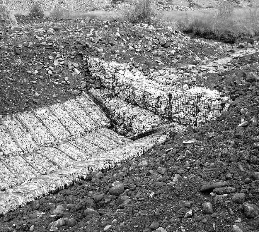
19 Figure 20: A Triton Marine Mattress is lowered over an underwater pipeline for protection. 3.7 MATTRESS PLACEMENT (INSTALLATION) General Place the filled units (typically on a prepared subgrade and geotextile filter) as called for in the contract documents or as directed by the engineer. See Figures 20 and 21. With appropriate detailing, geotextile may be pre-attached to the filled units prior to placement. Joining Adjacent Units Side-to-side seaming of adjacent units is not typically required, but if called for, can be accomplished by using a special braid material. For steep slopes, end-to-end splicing of adjacent mats can be accomplished by using the HDPE bar to form a bodkin connection. See Figure 14 on page 13 and Figure 22 on page 19. Anchoring Units For steep, sloping installations anchoring of the units may be required. If an extra length of grid is to be used as an anchor tail, it should be spliced to the lifting tab of the mattress unit using the HDPE bar to form a bodkin connection once the mattress unit is in place. See Figure 23 on page 19. If soil anchors are used to anchor the end of the grid, then special detailing is required to distribute the load from the anchor to the grid. Contact a Tensar Representative for suggested details. Figure 21: Completed installation for riverbank protection. 18


20 Finishing Treatments Special finishing treatments, such as top-dressing with soil and seeding, grouting or pouring a concrete surface on top of the mats should be considered ahead of time. Contact a Tensar Representative for suggested details. Top and bottom layers: Bodkin connection using 1.5 inch wide flat HDPE bar *Note: The overall mattress length when units are joined for lifting should not exceed the typical range as shown in Figure 13. End-to-end splice of mattress for lifting* Top layer: Bodkin connection using 1.5 inch wide flat HDPE bar Top layer: Bodkin connection using 1.5 inch wide flat HDPE bar Splicing a grid anchor tail to end of mattress Bottom layer: No connection unless otherwise specified or directed by the engineer End-to-end splice of mattress in place, after lifting Figure 22: End-to-end splicing of adjacent mattress units. Figure 23: An HDPE bar forms a bodkin connection.


21 Figure 24: Armor stone was placed directly on Triton Grid Composite in constructing a coastal groin. Another width of grid composite will be placed next to overlap the exposed edge of grid composite. Stone placement will then proceed toward the water. 4. Grid Composite System > The Triton Grid Composite System is specially developed for use beneath riprap and armor stone. By combining Tensar Biaxial (BX) Geogrids with geotextile, grid composites provide an improved foundation and filtration layer for a broad range of riprap, rubblemound and similar installations. For a complete application description, please refer to the Triton Systems Overview Brochure. 4.1 CUTTING GEOGRID STRIPS TO REQUIRED LENGTH Cut geogrids to lengths shown on the construction drawings.* Using a worktable, cut the geogrid with electric shears. See Figure 25. As each length of material is cut, mark it and tag it according to length, and stockpile it for later use.* You may want to connect several precut geogrid strips together side-by-side using HDPE braid. See Figure 26. This step can increase the speed of subsequent geogrid placement and is most often used on large projects. *Note: The correct geogrid lengths must be used at each section according to the project design. Figure 25: Cutting geogrid with a circular saw. Figure 26: Connecting precut geogrid using HDPE braid. 20
 GRID COMPOSITE Unless otherwise directed by the engineer, the BX Geogrid should be placed with the fabric side down, such that contact is maintained between the geotextile")
22 4.2 ANCHORING TRENCH EXCAVATION For use on grid composite slopes, excavate anchor trench as shown on the construction drawings or as directed by the engineer. See Figure PLACEMENT OF BIAXIAL (BX) GRID COMPOSITE Unless otherwise directed by the engineer, the BX Geogrid should be placed with the fabric side down, such that contact is maintained between the geotextile and the subgrade. Form the geogrid to the configuration of the trench and place it into the trench perpendicular to the slope face. Place a small amount of aggregate onto the geogrid to secure it in place during installation. Place geogrid down grade of slope surface. Adjacent geogrid strips should overlap per construction drawings. (If permitted by the project engineer, overlap may be minimized by joining the adjacent pieces using HDPE braid provided by Tensar International Corporation.) Figure 27: Excavate and unroll geogrid composite.


23 4.4 PLACEMENT OF AGGREGATE RIPRAP Fill in anchor trench. Additional aggregate should be placed on top of the anchor trench fill aggregate according to the engineering specifications.* All grid on top of slope must be fully covered to level as shown on construction drawings. See Figure 28. Place aggregate along side slopes. Aggregate placement should proceed from the toe of the slope and work to the top unless otherwise specified by the project engineer. Some projects may require the use of a backhoe. See Figure 29. *Note: Do not drive tracked vehicles on the uncovered geogrids. Rubber tired vehicles may be operated on top of the geogrid; however, sudden stops, excessive speed (over 15 mph) and sharp turns should be avoided. Figure 28: Spread and level aggregate. Figure 29: Place aggregate from toe of slope to top. 22


24 4.5 INSTALLATION IN SUBMERGED APPLICATIONS Cut geogrid composite to lengths shown on the construction drawings. Construct a steel frame suitable for attachment of the geogrid composite. See Figure 31. Use nylon cable ties to secure the geogrid composite to the steel frame. Using appropriate machinery (crane, excavator, etc.), lower the frame with attached geogrid composite into position as indicated in the construction drawings. Place a small amount of aggregate around the perimeter of the geogrid composite panel to secure the panel in place for the removal of the frame. With aggregate materials in place, it should be possible to remove the frame without disturbing the geogrid composite. The nylon cable ties should break easily, releasing the composite from the frame. Continue placing aggregate according to project plans and specifications.


25 Figure 30: Triton Grid Composites provide an improved foundation and filtration system. Figure 31: When placing Triton Grid Composite in a submerged application, a steel frame can be used for ease of installation. 24

26 Figure 32: Triton Gabion Mats provide long-term performance even in harsh chemical environments such as this saltwater tidal zone in Trinidad. 5. Gabions and Gabion Mats > Triton Gabions offer a durable, non-corrosive and installation-friendly alternative to conventional steel wire gabions including those galvanized and PVC-coated. They are advantageous for a number of earth stabilization and erosion protection applications. For a complete application description, please refer to the Triton Systems Overview Brochure. *Note: The following guidelines are suggested installation specifications for Tensar Gabion Baskets 1.5 feet and three feet deep. 5.1 ASSEMBLY 1. Open and stretch the pre-fabricated gabion on a hard flat surface. See Figure Raise the sides, ends and diaphragms, ensuring that all the creases are in the correct position and that the tops of all sides are even. 3. Bodkin joint, or lace, the two front face corners to the sides of the gabion. See Figure Lace the two remaining back-face-panel corners to the sides of the gabion, and then lace the internal diaphragms to the front and back panels. 5. To lace a gabion joint or corner, pass the cord around the two edges to be joined and tightly loop the cord twice through every aperture in turn.* Tie the cord off securely, turning the cord ends to the inside of the gabion upon completion. Cord lengths for lacing should not be less than three feet nor greater than six feet. *Note: When lacing a gabion joint or corner made from small (1 in. x 1.25 in.) aperture grid it is only necessary to loop the cord once through each aperture in turn. Gabion Diaphragm panel Face corner 12.0' Fold Line 9.0' Figure 33: Typical Triton Gabion prior to site assembly. Face corner Leave outside 2 inches unlaced. This is used in the bodkin joint assembly. Lacing 3.5' 3.0' 3.0'
.")

27 6. Use only the HDPE cord supplied by Tensar for all lacing.* Use a curved, wire-formed needle to simplify the lacing operation. 7. Position the assembled gabion in the structure as required (see Figure 35). The front face of the gabion should be faced outward, such that the final lacing will be in an unexposed condition to close the top of the lid. Secure the side, or end, from which work is to proceed to either the existing work or to the temporary rods driven firmly into the ground at the corners. The rods must reach at least to the top of the gabion. 8. When placing additional gabions in the structure, lace all corners and diaphragm points to the preceding unit using two cord turns per aperture opening (the filling of which should be deferred to facilitate the connection, except in the case of stacked units). *Note: Ultimate tensile strength in excess of 400 lbs. and stabilized with a 2.5% carbon black. 5.2 TENSIONING It is essential that the sidewalls of the gabion be tensioned before filling. With a firm anchorage, depending upon base friction, lengths of 24 to 60 feet may be tensioned simultaneously. A light winch secured to the free end of the gabion may be used to produce the necessary wall tautness and alignment. The tensioning force on each sidewall should not exceed 0.5 tons. See Figures 36 and 37 on page 27 and 28. Figure 34: Lace (or bodkin joint) the two front face corners to the sides of the gabion to form a box. Figure 35: Assembled Triton Gabion Mat. 26


28 While the gabions are under tension, securely lace together adjacent gabions along and throughout the length of all common edges (front, back, top, bottom, sides and diaphragms). Lacing should be carried out in a similar manner to that described for assembly of individual units, using just one cored turn per aperture opening. Do not release wall tension until sufficient fill has been placed to prevent wall slackening. 5.3 FILL MATERIAL Fill material shall conform to the project plans and specifications. In general, Tensar recommends that fill material should be a clean, hard, durable rock, which does not deteriorate when exposed to cycles of wetting and drying, or freezing and thawing. It should have a minimum size of 2.5 inches and a maximum size of 10 inches. A minimum of 60% of the fill must be larger than 2.5 inches with no more than 10% passing the #4 sieve. Secure end to existing work or a steel rod, like this rod embedded to suit ground conditions Winch method (Max force 0.5 tons) Windlass or straining wire method Figure 36: Triton Gabion tensioned in preparation for fill.

29 Figure 37: Triton Gabions should be filled with durable rock sized according to project plans and specifications. 5.4 FILLING Filling must take place while the gabion is under tension. 1. Place the fill in order to produce the minimum amount of voids. (Only the mechanical equipment approved by the engineer may be used for filling operations.) For fairface work, place select, squared rock by hand to provide a stable, dry joint with adjacent rocks. Gabions should be overfilled by 3 /4 to 1.5 inches to allow for settlement. 2. Temporarily thread a 1 /2 in. diameter rebar through the top of the diaphragm to prevent local deformation, or bulging, of the diaphragms during filling. Or, as an alternative, stage the filling of each compartment: For three feet deep gabions After the first gabion compartment has been filled, fill the second compartment to 2 /3 its depth, and the third compartment to 1 /3 its depth. For 1.5 feet deep gabions After the first gabion compartment has been filled, fill the second compartment to 1 /2 its depth. 28

30 5.5 INTERNAL BRACING To avoid excessive bulging of exposed gabion faces, internal bracing is required for three feet deep gabions. It should not be necessary for 1.5 feet deep gabions providing that a smooth curve, with an approximate three-inch eccentricity in the center of each panel, is acceptable to the engineer. When the three feet deep gabion has been filled to a depth of 1.5 feet, it should be internally braced using HDPE cord, as specified. 1. In each compartment, use two lengths of cord per exposed face placed equidistant from the ends, and running perpendicular to the exposed face. 2. Tie the cord around two adjacent diagonal rib nodes. 3. Pull the cord horizontally, hand tie and wrap it around a pair of nodes on the opposite face. 4. Tie-off without loosening tension. 5. Filling may then continue taking care not to damage the cord bracing. If internal bracing is required for 1.5 feet deep units, it should be fastened at mid-depth and tied in a similar manner to that described above for the three feet unit. Figure 38: Triton Gabion Mats are lightweight, customizable and easy to handle features that significantly ease installation.

31 5.6 SECURING THE LID Once the gabion has been filled, stretch the lid tightly over the fill and temporarily secure it at the corners. Tie the lid securely along the full length of all edges, ends and diaphragms by tightly looping the cord twice through every aperture and tying off securely. The length of any continuously tied joint should not be less than three feet nor greater than six feet. Turn the knotted ends of all cords into the gabion upon completion. 5.7 COMPLETED GABION The exposed faces of the completed gabion should present a neat face and line, with minimal bulging or depressions. The gabion should have well-packed fill, tight mesh and be securely laced. See Figure 39. Figure 39: This completed Triton Gabion in the Panama Canal is non-corrosive and extremely durable. 30

32 5.8 SPECIAL STRUCTURES OR ALTERATIONS Where shown on the drawings, or otherwise directed by the engineer, the gabion grid may be cut, folded and laced together to form mitre joints, angles, curves or slopes to accommodate any special structure features that may be required. Odd size or shape gabions pose no special problems, if the following guidelines are adhered to: The grid must be cleanly cut with all surplus material cut completely off and removed. Some special corners may require the odd overlap to be neatly laced to an adjacent gabion face. The cut edges of the grid shall be securely laced together with HDPE cord, looping tightly two turns through the aperture opening, in the manner described above. The assembly, erection, stretching, adjacent connections, filling and final lacing of the re-shaped gabions shall otherwise be carried out as described above.
33 32


34 6. Filter Mattresses > Triton Filter Mattresses were designed for challenging underwater installations, providing a deployment method to place geotextile fabric in deep water and strong currents. The filter mat serves two primary applications: Submerged revetment foundation Submerged geotextile deployment Figure 40: As a revetment foundation, the Triton Filter Mattress provides bedding and filtration, helping to prevent differential settlement. The mats also protect against scour at the toe of the revetment. Figure 41: The Triton Filter Mattress System was installed to help improve the performance of the seawall protection at the Hereford Inlet Seawall project in North Wildwood, New Jersey.


 *Note: These optional details are typically reserved for special cases.")
35 Figure 42: Stand all baffles upright and hold in place with cable ties prior to lacing with braid material. 6.1 BOXING-UP Work Area Lay the mats flat; this work is typically accomplished directly on the ground or in a stack of mats on the ground. If worktables are used at this stage they will need to be roughly the same size as the mats. See Figure 42. Box Up Assembly Make all the vertical seams, including seaming the sides to the ends and baffles. See Figure 43. After this point of fabrication, avoid rolling or flattening the mats. Optional Lining or Pre-Attached Geotextile Where called for, place the geotextile within the compartments or attach it to the bottom of the mats prior to filling.* (Generally completed in prefabrication.) *Note: These optional details are typically reserved for special cases. Figure 43: When lacing the various seams of the Triton Filter Mattress, use a standard half-hitch knot. 34

 is suggested for the sides and ends to expedite filling.")


36 Figure 44: Once the baffles have been laced to the side panels, wooden frames can be inserted into the compartments to provide support to the baffles during the filling process. 6.2 FILLING Work Area Same as boxing-up stage, except worktables are typically not an option due to the weight of the filled mats. Edge support (such as a staked board, a heavy beam or a filled mat) is suggested for the sides and ends to expedite filling. Filling may be accomplished in place if desired. Securing the Position of the Baffles Use tension or manually placed stone fill to support the baffles in an upright position, ready for filling. Wooden frames can be inserted into the compartments for support as well. See Figures 44 and 45. Filling the Compartments Dump stone in each compartment by equipment bucket or hopper manually. See Figure 46. The filling operation should be conducted in a manner to avoid folding or flattening of the baffles, sides or ends. Spread the stone fill. If sufficient care is exercised to avoid damage to the mat materials, equipment may be used for the rough spreading of stone fill within the compartments. Figure 45: It may be beneficial to secure the baffles to the frame with lightweight cable ties to prevent them from folding under the stone as it is placed within the compartments.


37 Figure 46: With the frames in place, stone fill can be loaded into the mattress unit. Final spreading should be accomplished manually. The stone fill should be slightly heaped in the center of each compartment, such that the stone fill is slightly above the top of the sides, ends and baffles as shown in Figure 48. The average thickness of the mat should not exceed the nominal thickness shown on the drawings. Positioning, Splicing and Securing the Top Splice together the flaps of the main piece of grid over the top of the mat to form the top layer of grid. See Figure 47. Leaving sufficient length for the lifting hoop on each end of the mat, seam the ends, sides and baffles to the top. See Figure 49 on page 37. The top should be pulled down snugly against the stone fill such that the grid is reasonably taut and each mat is reasonably free of unfilled spaces. See Figures 50 and 51 on page 37. Figure 47: Once filled, the geogrid at the ends of the mattress are laid over the filled portion of the mat to form the lid. Figure 48: Each compartment should be filled slightly higher than the top of the baffles. 36
 as called for in the contract documents or as directed by the engineer. 2.")


38 Figure 49: Tie the long seams of the mattress using the same stitch configuration shown here. 6.3 LIFTING, HANDLING AND PLACING FILLED MATS 1. Place the filled mats (typically on a prepared subgrade) as called for in the contract documents or as directed by the engineer. 2. The contractor is responsible for providing adequate rigging and equipment, and to use safe procedures in the lifting, handling and placement of the filled mats. See Figure The geogrid must be loaded uniformly during lifting. This requires that: The mat ends, lifting hoops and lifting bars hang in a level and horizontal position during lifting. Each lifting bar is rigged to pivot freely with the mats. Each lifting bar is adequate to safely carry the load without bending or sagging. The rigging, equipment and procedures are adequate to prevent excessive swinging or jostling of the mats. 4. Personnel must maintain a safe distance from the mats, rigging and equipment at all times during lifting. Personnel should never be in the area beneath a filled mat during lifting. Tag lines should be used to help guide and position the mats during installation. 5. No mat should be left hanging in the lifting position for an extended period of time. A typical timeframe for lifting, handling and placement is considered to be five to fifteen minutes. Figure 50: Tie the lid to the baffles. It may be helpful to fabricate a wire hook to help pull the braid materials up through the mattress lid. Figure 51: The completed mattress unit should appear full and slightly bulged in-between baffles.

39 Rigging and steel lifting bar Geogrid lifting hoop Spreader Beam Distance approximately equal to mat length Typical Two-Ended Lift Splice Point 20 ft 6.5 ft Typical One-Ended Lift 6 inches General Notes: Lifting bar, rigging and handling must be suitable to distribute the lifting loads uniformly to the geogrid. Lifting apparatus to be proposed by contractor. Handling and lifting of grid materials and mattresses shall be avoided when the ambient temperature is lower than 5 degrees below zero, C. Stone-filled compartments shall be formed by the use of internal baffles across each mat at a maximum spacing of approximately 2 feet. All exterior sides and interior baffles and lifting hoops shall be formed with Tensar BX1500 grid. See the Project Specifications regarding stone fill materials. Filling shall be accomplished such that the average thickness of each mattress does not exceed 6 inches. NOT TO SCALE Figure 52: Typical configuration of filled Triton BX Filter Mattress Units. 38
40 Tensar International Corporation 5883 Glenridge Drive, Suite 200 Atlanta, Georgia TENSAR-1 Authorized Representative: 2007, Tensar International Corporation, Limited LLC, Inc. Certain products and/or applications described or illustrated herein are protected under one or more U.S. patents. Other U.S. patents are pending, and certain foreign patents and patent applications may also exist. Trademark rights also apply as indicated herein. Final determination of the suitability of any information or material for the use contemplated, and its manner of use, is the sole responsibility of the user. Printed in the U.S.A. TRITON_IG_6.07
INS T A LLA T I O N G U I D E
 INS T A LLA T I O N G U I D E TENSAR GEOGRIDS The System is a costeffective and easy-to-install alternative for projects with grade changes. The System owes its long-term performance and durability to
Click on image to enlarge.
 Assembly Open the bundle and unfold each unit. Lift the sides, the ends and the diaphragms of each unit into vertical position. Attach the sides of four corners together with locking wire fastener or lacing
TION GUIDE ALLA T INS
 INSTALLATION GUIDE TENSAR GEOGRIDS Easier installation makes the Sierra Slope Retention System a more affordable alternative to conventional retaining walls. The Sierra System owes its strength and durability
ROAD COMMISSION FOR OAKLAND COUNTY. SPECIAL PROVISION FOR GABION WALL RCOC/DESIGN: AB Page 1 of 8 RCOC12SP706F 10/28/2013
 ROAD COMMISSION FOR OAKLAND COUNTY SPECIAL PROVISION FOR GABION WALL RCOC/DESIGN: AB Page 1 of 8 RCOC12SP706F a. Description This work shall be done in accordance with Section 205 and 206 of the 2012 Michigan
GABIONS AND REVET MATTRESSES
 GABIONS AND REVET MATTRESSES PART 1 - GENERAL 1.01 SECTION INCLUDES A. Gabions B. Revet Mattresses (Gabion Mattresses) 1.02 DESCRIPTION OF WORK A. Assembly and installation of gabions. B. Assembly and
SECTION MECHANICALLY STABILIZED EARTHEN SLOPES. Display hidden notes to specifier by using Tools / Options / View / Hidden Text.
 PART 1 GENERAL SECTION 02260 MECHANICALLY STABILIZED EARTHEN SLOPES Display hidden notes to specifier by using Tools / Options / View / Hidden Text. 1.1 SECTION INCLUDES A. ** NOTE TO SPECIFIER ** Delete
SECTION MECHANICALLY STABILIZED EARTH 1.01 SUMMARY
 SECTION 028300 PART 1 GENERAL 1.01 SUMMARY A. Section includes Basis of Design Mechanically Stabilized Earth System: SierraScape Mechanically Stabilized Earth (MSE) retaining wall system having high density
GABIONS PVC Coated. Product Standard Specifications Installation Instructions Method of Measurement and Payment. Update: May 1999
 PSS-GBPVC.doc - Page 1 GABIONS PVC Coated Product Standard Specifications Installation Instructions Method of Measurement and Payment Update: May 1999 ENVIRONMENTAL SOLUTIONS PSS-GBPVC.doc - Page 2 FOREWORD
GABIONS - Galvanized
 PSS-GBZN - Page 1 GABIONS - Galvanized Product Standard Specifications Installation Instructions Method of Measurement and Payment Update: May 1999 ENVIRONMENTAL SOLUTIONS PSS-GBZN - Page 2 FOREWORD This
GEOSYTHETIC SLOPE SPEC-V0704rev.doc STANDARD SPECIAL PROVISION FOR GEOSYNTHETIC REINFORCED SLOPE CONSTRUCTION
 GEOSYTHETIC SLOPE SPEC-V0704rev.doc STANDARD SPECIAL PROVISION FOR GEOSYNTHETIC REINFORCED SLOPE CONSTRUCTION I. DESCRIPTION - This work consists of furnishing the required materials and construction of
Retaining Wall Systems
 Retaining Wall Systems Construction & Quality Control Tensar Earth Technologies, Inc. Manual CONSTRUCTION & QUALITY CONTROL This manual provides general guidelines for construction and quality control
67665_MesaInstallationGuide_2 12/10/07 2:12 PM Page 1 E ID U G TION ALLA T INS
 INSTALLATION GUIDE Introduction The Mesa Retaining Wall Systems from Tensar International Corporation offer superior and costeffective solutions for all of your retaining wall needs. This installation
SECTION SPECIFICATION FOR MECHANICALLY STABILIZED EARTH TWO STAGE WALL SYSTEM
 SECTION 02830 SPECIFICATION FOR MECHANICALLY STABILIZED EARTH TWO STAGE WALL SYSTEM ## THIS SECTION IS WRITTEN IN CSI 3-PART FORMAT AND IN CSI PAGE FORMAT. NOTES TO THE SPECIFIER, SUCH AS THIS, ARE INDICATED
PaveDrain Installation Manual. Table of Contents. Hand-Placement of individual PaveDrain Units. PaveDrain End Cap
 Installation Manual PaveDrain Installation Manual Table of Contents Section 1: Base Preparation Section 2: Hand-Placement of individual PaveDrain Units Section 3: Mattress Installation Section 4: PaveDrain
1:100 GABION WALLS LEGEND NOT FOR CONSTRUCTION TYPICAL DRAWING TEXT SETTING TYPE CHARACTER HEIGHT PEN SETUP FOR PLOTTING SUBTITLE
 LEGEND SHEET 0 BATTERED WALLS - TYPICAL SECTIONS AND CONSTRUCTION S VERTICAL WALLS - TYPICAL SECTIONS AND CONSTRUCTION S AND CONSTRUCTION S SHEET 02 SHEET 0 SHEET 04 RETAINING STRUCTURES WITH CUT OFF WALLS
ITEM 432 RIPRAP. Dry Riprap is defined as Stone Riprap of the required type with voids filled only with spalls or small stones.
 ITEM 432 RIPRAP 432.1. Description. This Item shall govern for the furnishing and placing of riprap of the type and details shown on the plans and in accordance with this Item. 432.2. General. Riprap furnished
Reinforced Soil Slopes (RSS)
") Supplemental Technical Specification for Reinforced Soil Slopes (RSS) SCDOT Designation: SC-M-206-1 (4/16) 1.0 DESCRIPTION 1.1 Construct a reinforced soil slope in accordance with these specifications,
Supplemental Technical Specification for Reinforced Soil Slopes (RSS) SCDOT Designation: SC-M-206-1 (4/16) 1.0 DESCRIPTION 1.1 Construct a reinforced soil slope in accordance with these specifications,
CONCRETE SEGMENTAL RETAINING WALL SYSTEM
 CONCRETE SEGMENTAL RETAINING WALL SYSTEM PART 1: GENERAL SPECIFICATIONS 1.01 Work Included A. Work shall consist of furnishing and constructing a Rockwood Classic 8, Classic 6 and Legend unit segmental
MagnumStone Specifications Gravity
 MagnumStone Specifications Gravity SPECIFICATION FOR MAGNUMSTONE GRAVITY MECHANICALLY STABILIZED EARTH SYSTEM PART 1: GENERAL.01Description The work consists of supplying and installing all aspects of
SECTION CHAIN LINK FENCES
 SECTION 02 44 40 PART 1 - GENERAL 1.1 DESCRIPTION A. Work included: Provide chain link fence system where shown on the Drawings, as specified herein, and as needed for a complete and proper installation.
HUITEX GEOCELL INSTALLATION MANUAL
 Table of Contents 1 Site Preparation 2 Installation for the Retaining Wall 2.1 Base Preparation 2.2 Footing Installation 2.3 Placement of the Drainage System 2.4 Placement of the HUITEX Geocell panels
SECTION 1208 CHAIN LINK FENCING DESCRIPTION
 SECTION 1208 CHAIN LINK FENCING 1208-1 DESCRIPTION This item covers the requirements for furnishing materials and constructing new chain link fences and gates in accordance with the details included herein
SIERRASCAPE RETAINING WALL SYSTEM. design and installation guide
 SIERRASCAPE RETAINING WALL SYSTEM design and installation guide The Retaining Wall System is a more affordable alternative to concrete panel or block walls for various grade change challenges. Engineers
Gabions. Introduction
 Gabions Introduction 1. A gabion is a wire mesh cage or basket filled with stones. Gabions are useful in construction works, for example to protect earth embankments, to line channels, to manage or divert
SPECIFICATIONS FOR PRECAST MODULAR BLOCK RETAINING WALL SYSTEM (revised 5/8/7)
") Page 1 of 7 STONE STRONG SYSTEMS SPECIFICATIONS FOR PRECAST MODULAR BLOCK RETAINING WALL SYSTEM (revised 5/8/7) PART 1: GENERAL 1.01 Description A. Work includes furnishing and installing precast modular
Page 1 of 7 STONE STRONG SYSTEMS SPECIFICATIONS FOR PRECAST MODULAR BLOCK RETAINING WALL SYSTEM (revised 5/8/7) PART 1: GENERAL 1.01 Description A. Work includes furnishing and installing precast modular
Section ( ) SPECIFICATION FOR SEGMENTAL CONCRETE UNIT RETAINING WALL
 SPECIFICATION FOR SEGMENTAL CONCRETE UNIT RETAINING WALL") Section 02834 (32 32 23) SPECIFICATION FOR SEGMENTAL CONCRETE UNIT RETAINING WALL PART 1: GENERAL 1.01 Description A. Work shall consist of furnishing and construction of a County Materials Retaining Wall
Section 02834 (32 32 23) SPECIFICATION FOR SEGMENTAL CONCRETE UNIT RETAINING WALL PART 1: GENERAL 1.01 Description A. Work shall consist of furnishing and construction of a County Materials Retaining Wall
ArmorFlex. Articulating Concrete Block Revetment System
 ArmorFlex Articulating Concrete Block Revetment System ArmorFlex ASTM-validated system lets you design with confidence ArmorFlex is in a class by itself. Developed for high-scour, high-flow applications,
SECTION CHAIN LINK FENCES AND GATES (PARK)
") SECTION 02821 CHAIN LINK FENCES AND GATES (PARK) PART I GENERAL 1.1 SECTION INCLUDES A. Installation of chain link fences, and gate units provided by single source including erection accessories, fittings,
SECTION 02821 CHAIN LINK FENCES AND GATES (PARK) PART I GENERAL 1.1 SECTION INCLUDES A. Installation of chain link fences, and gate units provided by single source including erection accessories, fittings,
SPECIFICATIONS FOR PRECAST MODULAR BLOCK RETAINING WALL SYSTEM (revised 9/17/18)
") Page 1 of 8 STONE STRONG SYSTEMS SPECIFICATIONS FOR PRECAST MODULAR BLOCK RETAINING WALL SYSTEM (revised ) PART 1: GENERAL 1.01 Description A. Work includes furnishing and installing precast modular blocks
Page 1 of 8 STONE STRONG SYSTEMS SPECIFICATIONS FOR PRECAST MODULAR BLOCK RETAINING WALL SYSTEM (revised ) PART 1: GENERAL 1.01 Description A. Work includes furnishing and installing precast modular blocks
Installation Manual. ArchCast Bridge. 3-Sided Precast Concrete Bridge Structure
 ArchCast Bridge 3-Sided Precast Concrete Bridge Structure Installation Manual Salem Location: 749 West Commercial Ave. Salem, IL 62881 (618) 548-1190 countymaterials.com Email: info@countymaterials.com
Design and Installation Guidelines for Retaining Walls. 1 P age. Geo Products, LLC 8615 Golden Spike Lane Houston, TX Phone:
 Design and Installation Guidelines for Retaining Walls 1 P age Geo Products, LLC 8615 Golden Spike Lane Houston, TX 77086 Phone: 281.820.5493 2011 Geo Products, Fax: 281.820.5499 LLC www.geoproducts.org
ITEM 750 ROCK FILTER DAMS
 AFTER MARCH 1, 2012 ITEM 750 ROCK FILTER DAMS 750.1 Description. This work shall consist of the installation of temporary erosion protection and sediment control rock filter dams utilized during construction
GEOSYNTHETICS USED IN SUBGRADE STABILIZATION
 GEOSYNTHETICS USED IN SUBGRADE STABILIZATION Prepared by: TenCate Geosynthetics Americas 365 South Holland Drive Pendergrass, GA 30567 Tel. (706) 693-2226 Fax (706) 693-2044 www.tencate.com July, 2013
TENAX TT MONO-ORIENTED HDPE GEOGRID
 TENAX TT MONO-ORIENTED HDPE GEOGRID Rev June 2013 Sales orders / enquiries - Email sales@gtsl.co.nz - Phone 0800 436 832 - www.geotechsystems.co.nz Page 2 of 39 Rev June 2013 Sales orders / enquiries -
CONSTRUCTION SPECIFICATION FOR INSTALLATION OF GABIONS
 ONTARIO PROVINCIAL STANDARD SPECIFICATION OPSS.MUNI 512 NOVEMBER 2017 CONSTRUCTION SPECIFICATION FOR INSTALLATION OF GABIONS TABLE OF CONTENTS 512.01 SCOPE 512.02 REFERENCES 512.03 DEFINITIONS 512.04 DESIGN
MODULAR CONCRETE RETAINING WALL
 MODULAR CONCRETE RETAINING WALL PART 1: GENERAL 1.01 Description A. Work shall consist of furnishing and construction of a KEYSTONE Retaining Wall System or equal in accordance with these specifications
SPECIFICATION FOR CORNERSTONE GEOGRID REINFORCED SEGMENTAL RETAINING WALL SYSTEM
 CornerStone Specifications Geogrid Reinforced SPECIFICATION FOR CORNERSTONE GEOGRID REINFORCED SEGMENTAL RETAINING WALL SYSTEM PART 1: GENERAL 1.01 Description The work consists of supplying and installing
SECTION 1043 FENCE MATERIAL
 SECTION 1043 FENCE MATERIAL 1043.1 Scope. This specification covers the material required in the construction of chainlink fence and woven wire fence. 1043.2 Basis of Acceptance. The basis of acceptance
Section ( ) MODULAR CONCRETE RETAINING WALL
 MODULAR CONCRETE RETAINING WALL") Section 02834 (32 32 23) MODULAR CONCRETE RETAINING WALL PART 1: GENERAL 1.01 Description A. Work shall consist of furnishing and construction of a KEYSTONE 133Elite Unit Retaining Wall System or equal
Section 02834 (32 32 23) MODULAR CONCRETE RETAINING WALL PART 1: GENERAL 1.01 Description A. Work shall consist of furnishing and construction of a KEYSTONE 133Elite Unit Retaining Wall System or equal
Strengthened Soil Wall Construction Manual
 Strengthened Soil Wall Construction Manual This information has been prepared by Shaw Technologies, Inc. as an aid in constructing their Strengthened Soil Wall system. Final determination of the suitability
MACHINE-LAY Installation Manual
 MACHINE-LAY Installation Manual PaveDrain Installation Manual Table of Contents Section 1: Base Preparation (pages 3 6) Section 2: Machine-Lay PaveDrain Blocks (pages 8 11) Section 3: Edge Restraints (pages
Channel FlexTM P-BD Series
 Channel FlexTM P-BD Series Class 475 Closed Cell 4.75 Cellular Concrete Block Mat System TABLE OF CONTENTS FOR ARTICULATED CONCRETE BLOCK REVETMENT PARAGRAPH PARAGRAPH TITLE PAGE PART 1 - GENERAL 1.1 DEFINITIONS
SPECIFICATION FOR MAGNUMSTONE GEOGRID REINFORCED Mechanically Stabilized Earth (MSE) SYSTEM
 SYSTEM") MagnumStone Specifications Geogrid Reinforced SPECIFICATION FOR MAGNUMSTONE GEOGRID REINFORCED Mechanically Stabilized Earth (MSE) SYSTEM PART 1: GENERAL 1.01 Description The work consists of supplying
MagnumStone Specifications Geogrid Reinforced SPECIFICATION FOR MAGNUMSTONE GEOGRID REINFORCED Mechanically Stabilized Earth (MSE) SYSTEM PART 1: GENERAL 1.01 Description The work consists of supplying
CONSOLIDATED EDISON COMPANY OF NEW YORK, INC. 4 IRVING PLACE NEW YORK, NY DISTRIBUTION ENGINEERING DISTRIBUTION EQUIPMENT
 CONSOLIDATED EDISON COMPANY OF NEW YORK, INC. 4 IRVING PLACE NEW YORK, NY 10003 DISTRIBUTION ENGINEERING DISTRIBUTION EQUIPMENT SPECIFICATION EO-1124 REVISION 3 November 2013 EFFECTIVE DATE November 11,
GEOGRID CONNECTION DETAIL OLYMPIA RADIUS UNIT
 PLACE TWO STANDARD CONNECTORS IN EACH UNIT AS SHOWN (VERTICAL ORIENTATION) INSERT TWO CONNECTORS PER HORIZONTALLY ORIENTED BLOCK; INSERT ONE CONNECTOR PER VERTICALLY ORIENTED BLOCK SHIM BETWEEN BLOCK COURSES
ARES Retaining Wall Systems >
 SYSTEM OVERVIEW Tensar Geogrids When reliability and speed of construction are concerns, ARES Walls offer unmatched advantages. The ARES Systems owe their strength and durability to Uniaxial (UX) Geogrids,
A Complete Retaining Wall Solution >
 SYSTEM OVERVIEW Tensar Geogrids SierraScape Walls now offer a more affordable alternative to concrete for steep grade changes. The SierraScape System owes its strength and durability to Uniaxial (UX) Geogrids,
CITY OF MOUNT DORA LIFT STATION CHAINLINK FENCE AND GATE SPECIFICATIONS
 CITY OF MOUNT DORA LIFT STATION CHAINLINK FENCE AND GATE SPECIFICATIONS PART 1 - GENERAL 1.01 SUMMARY A. Section Includes furnishing and installing chain-link fabric fence, gate, and appurtenances. 1.02
Important: Before You Start
 Advantage ICF System Advantage ICF System TM Field Guide Important: Before You Start Does Your Building Inspector Know You Are Building with the Advantage ICF System? You are required to check with your
ROLLED EROSION CONTROL PRODUCTS (RECP)
") Supplemental Technical Specification for ROLLED EROSION CONTROL PRODUCTS (RECP) SCDOT Designation: SC-M-815-9 (07/17) 1.0 Rolled Erosion Control Products (RECP) This Supplemental Specification replaces
Supplemental Technical Specification for ROLLED EROSION CONTROL PRODUCTS (RECP) SCDOT Designation: SC-M-815-9 (07/17) 1.0 Rolled Erosion Control Products (RECP) This Supplemental Specification replaces
Miller Collective Safety at Height Solutions EPIC ULTRA Barrier System EPIC Post-N-Barrier System EPIC Basic Barrier System
 For over 65 years the Miller brand has been synonymous with personal fall protection products and services. As the global leader in safety at height solutions, Honeywell Safety Products introduces a new
Section ( ) KEYSTONE CONCRETE RETAINING WALL
 KEYSTONE CONCRETE RETAINING WALL") Section 02834 (32 32 23) KEYSTONE CONCRETE RETAINING WALL PART 1: GENERAL 1.01 Description A. Work shall consist of designing, furnishing and construction of a KEYSTONE Compac Unit Retaining Wall System
Section 02834 (32 32 23) KEYSTONE CONCRETE RETAINING WALL PART 1: GENERAL 1.01 Description A. Work shall consist of designing, furnishing and construction of a KEYSTONE Compac Unit Retaining Wall System
A.2.a Random Riprap... Table
 3601 RIPRAP MATERIAL 3601.1 SCOPE Provide stone and filter layer material for use in random or hand-placed riprap, gabion, and revet mattress construction. 3601.2 REQUIREMENTS A Stones A.1 Quality Provide
CHAPTER 15 - GABIONS, EROSION PROTECTION
 CHAPTER 15 - GABIONS, EROSION PROTECTION GW Els 15.1 INTRODUCTION The focus of this chapter is the practical aspects of the more commonly used bank protection and erosion protection techniques. For design
APPLICATION BULLETIN. TENSAR GRADE SEPARATION SOLUTIONS FOR HEAVY RAIL AND MASS TRANSIT l
 APPLICATION BULLETIN TENSAR GRADE SEPARATION SOLUTIONS FOR HEAVY RAIL AND MASS TRANSIT l Tensar International Corporation Offers Rail Engineers a Wide Variety of Solutions for Railway Applications > For
TERRASTOP SYSTEM 2 RETAINING WALLS. Section Page 1 PART 1 - GENERAL 1.1 SUMMARY
 Section 02832 - Page 1 PART 1 - GENERAL 1.1 SUMMARY 1.2 DEFINITIONS 1.3 SUBMITTALS 1.4 JOB MOCK-UP A. This section includes furnishing and installation of modular interlocking concrete masonry units bearing
Flexamat Erosion Control Mat
 Flexamat Erosion Control Mat 1. DESCRIPTION 2. MATERIALS Furnish and install Flexamat Erosion Control Mats. Submit manufacturer s performance research results and calculations in support of the Flexamat
Installation Guidelines
 815 NE 172 nd Avenue Vancouver, WA 98684 877-694-0141 Installation Guidelines Installation steps include job planning, layout, excavating and preparing the soil subgrade, applying geotextiles (optional),
SPECIFICATION FOR REINFORCED SOIL WALL
 SPECIFICATION FOR REINFORCED SOIL WALL 1.0 EXTENT OF WORK The work shall consist of Reinforced Soil walls built in accordance with this specification and in conformity with the lines, levels and details
A. Modular Unit - A concrete wall interlocking element, machine made from portland cement, water and aggregates.
 Section 02832 - Page 1 PART 1 - GENERAL 1.1 SUMMARY 1.2 DEFINITIONS 1.3 SUBMITTALS 1.4 JOB MOCK-UP A. This section includes furnishing and installation of modular interlocking concrete masonry units bearing
T-WALL Retaining Wall System
 CONSTRUCTION MANUAL T-WALL Retaining Wall System The T-WALL Solution... THE NEEL COMPANY 8328 Traford Lane Springfield, VA 22152 Phone 703-913-7858 Fax 703-913-7859 T-WALL Retaining Wall System CONSTRUCTION
Reinforced Earth wall Construction Manual
 COVER PAGE CT-PE-W02 Rev: 5 Reinforced Earth wall Construction Manual Concrete Facing Reinforced Earth Malaysia Sdn Bhd 80-1, Jalan 8/62A Bandar Menjalara 52200 Kuala Lumpur Tel : 03-62746162, Fax : 03-62747212
Nantasket Beach Revetment Design
 Nantasket Beach Revetment Design A design concept for a stone revetment was developed for the conditions reported in the 20 May 2008 Draft Nantasket Beach Coastal Engineering Appendix. This revetment design
Concrete Cloth. Geosynthetic Cementitious Composite Mat (GCCM) INSTALLATION GUIDE
 INSTALLATION GUIDE") Concrete Cloth Geosynthetic Cementitious Composite Mat (GCCM) INSTALLATION GUIDE Overview This document provides guidance for the installation of Milliken s Concrete Cloth material under field conditions.
Concrete Cloth Geosynthetic Cementitious Composite Mat (GCCM) INSTALLATION GUIDE Overview This document provides guidance for the installation of Milliken s Concrete Cloth material under field conditions.
SECTION 2831 ITEM F-162 CHAIN-LINK FENCES
 SECTION 2831 ITEM F-162 CHAIN-LINK FENCES PART 1 - GENERAL 1.1 DESCRIPTION. This item shall consist of furnishing and erecting a chain-link fence in accordance with these specifications and the details
1 Exam Prep Placing Reinforcing Bars Tabs and Highlights
 1 Exam Prep Placing Reinforcing Bars Tabs and s These 1 Exam Prep Tabs are based on the CRSI Placing Reinforcing Bars Recommended Practices, 9 th Edition. Each 1 Exam Prep tabs sheet has five rows of tabs.
Interior Hangers. Application
 Application Interior bridge deck hangers are typically fabricated using two heavy duty sheet metal end clips that have been electrically resistance welded to an appropriate sized wire or formed metal connecting
Product Guide. Fabric-formed Concrete Erosion Control and Armoring Systems. Filter Point. Filter Band. Uniform Section. Enviromat. Articulating Block
 Filter Point Filter Band Uniform Section Enviromat Articulating Block Hydrocast Armor Units Fabric-formed Concrete Erosion Control and Armoring Systems Product Guide Filter Point (FP) Linings Filter Band
Drop-In Specification Standard Flexamat Erosion Control System (English Units)
") Drop-In Specification Standard Flexamat Erosion Control System (English Units) The following specification is a sample guideline to be customized by the engineer as needed for preparing a site-specific
Drop-In Specification Standard Flexamat Erosion Control System (English Units) The following specification is a sample guideline to be customized by the engineer as needed for preparing a site-specific
CONSTRUCTION MANUAL. T-WALL Retaining Wall System FOR RAILROAD PROJECTS. The T-WALL Solution...
 T-WALL Retaining Wall System CONSTRUCTION MANUAL FOR RAILROAD PROJECTS T-WALL railroad units are 5.0' high x 7.5' wide. (stem lengths will vary) The T-WALL Solution... T-WALL Retaining Wall System CONSTRUCTION
ITEM 555 CHAIN LINK FENCING
 ITEM 555 AFTER MARCH 1, 2012 CHAIN LINK FENCING 555.1 Description. This item shall govern for furnishing the quantities of chain link fencing and gates as shown on the plans, including all posts, bracing
Section Gabions Tender No. [ ] Page The following detail drawings are appended hereto and form part of this section.
![Section Gabions Tender No. [ ] Page The following detail drawings are appended hereto and form part of this section.](/thumbs/86/94625619.jpg "Section Gabions Tender No. [ ] Page The following detail drawings are appended hereto and form part of this section.") Tender No. [ ] Page 1 1.0 GENERAL 1.1 DETAILED DRAWINGS.1 The following detail drawings are appended hereto and form part of this section. Number Title 02374.01 Gabion Basket Assembly Details 02374.02
Tender No. [ ] Page 1 1.0 GENERAL 1.1 DETAILED DRAWINGS.1 The following detail drawings are appended hereto and form part of this section. Number Title 02374.01 Gabion Basket Assembly Details 02374.02
SECTION SEGMENTAL CONCRETE UNIT MASONRY RETAINING WALL MAXIMUM HEIGHT OF 5-0 HIGH
 DIVISION 32 EXTERIOR IMPROVEMENTS SECTION 32 32 23.13 SEGMENTAL CONCRETE UNIT MASONRY RETAINING WALL MAXIMUM HEIGHT OF 5-0 HIGH PART 1: GENERAL 1.01 Scope of Standards A. This standard provides general
SECTION MECHANICALLY STABILIZED EARTH RETAINING WALLS
 SECTION 13100 MECHANICALLY STABILIZED EARTH RETAINING WALLS PART 1 -- GENERAL 1.01 THE REQUIREMENT A. Includes all labor, material, equipment, testing and submittals required to design and complete construction
INSTALLATION MANUAL FOR MODULAR EXPANSION JOINT (LG SYSTEM)
") INSTALLATION MANUAL FOR MODULAR EXPANSION JOINT (LG SYSTEM) TABLE OF CONTENTS 1. INTRODUCTION TO THE MODULAR EXPANSION JOINT 1.1 Purpose 1.2 How They Work 1.3 Movement Capacity 1.3.1 Longitudinal Direction
INSTALLATION MANUAL FOR MODULAR EXPANSION JOINT (LG SYSTEM) TABLE OF CONTENTS 1. INTRODUCTION TO THE MODULAR EXPANSION JOINT 1.1 Purpose 1.2 How They Work 1.3 Movement Capacity 1.3.1 Longitudinal Direction
StormTech Construction Guide
 A division of StormTech solid end caps and pre-cored end caps StormTech chambers StormTech manifolds and fittings Acceptable fill materials per Table 1 Woven and non-woven geotextiles 80-7 DC REQUIRED
MODULO GEOBENT Installation Guidelines
 MODULO GEOBENT Installation Guidelines SUBGRADE PREPARATION The relative thinness of GCLs requires that more attention be given to subgrade preparation than should be given during the construction of a
Flexamat Tied Concrete Block Mats
 Flexamat Tied Concrete Block Mats 1. DESCRIPTION 2. MATERIALS Flexamat Tied Concrete Block Erosion Control Mats This work shall consist of furnishing and placing the Flexamat system in accordance with
SIERRASCAPE RETAINING WALL SYSTEM. design and installation guide
 SIERRASCAPE RETAINING WALL SYSTEM design and installation guide The Retaining Wall System is a more afordable alternative to concrete panel or block walls for various grade change challenges. Engineers
TITLE: CAMP JOHNSON OVERPASS / HWY 17 BYPASS SECURITY FENCE UPGRADES
 CONTRACT # N40085-15B-0457 PROJECT # 15R036CN MACC # 15-0457 MAXIMO# 4608934 TITLE: CAMP JOHNSON OVERPASS / HWY 17 BYPASS SECURITY FENCE UPGRADES ATTACHMENTS: 1. 15-0457 CJ OVERPASS SECURITY UPGRADES Site
Houston Community College 3200 Main Parking Garage November 15, 2010 Houston Community College
 SECTION 323113 - CHAIN LINK FENCES AND GATES PART 1 - GENERAL 1.1 RELATED DOCUMENTS A. Drawings and general provisions of the Contract, including General and Supplementary Conditions and Division 01 Specification
2-16 EROSION, SEDIMENT & STORM WATER CONTROL REGULATIONS APPENDIX B1
 2-16 EROSION, SEDIMENT & STORM WATER CONTROL REGULATIONS APPENDIX B1 There are three ways to accomplish urban soil erosion and sedimentation control: Allow erosion to take place and then control sediment
Wmega Retaining Wall Specification
 Wmega Retaining Wall Specification 1. General 1.01 Description A. This work shall consist of furnishing and installing an Ωmega Segmental Retaining Wall System in accordance with these specifications and
DETAIL INSTRUCTION No. 1
 BEFORE BEGINNING INSTALLATION, PLEASE READ THROUGH ALL INSTRUCTIONS. Uncrate shipment and check against packing list to insure all materials are included before beginning installation. If any discrepencies
Monumental Blok. Pallet Overview. Compatible caps. Notes. code 3521 (a) 3522 (b) 3523 (c) texture Chiseled. Specifications per pallet.
 3522 (b) 3523 (c) texture Chiseled. Specifications per pallet.") Monumental Blok code 3521 (a) 3522 (b) 3523 (c) texture Chiseled Pallet Overview (see below) HALF Specifications per pallet Imperial Metric Cubing 13.80 ft 2 /pal. (1.28 m 2 )/pal. 1.73 ft 2 /unit (0.16
Monumental Blok code 3521 (a) 3522 (b) 3523 (c) texture Chiseled Pallet Overview (see below) HALF Specifications per pallet Imperial Metric Cubing 13.80 ft 2 /pal. (1.28 m 2 )/pal. 1.73 ft 2 /unit (0.16
Concrete Framing Systems - Walls and Columns
 Concrete Framing Systems - Walls and Columns Casting a Concrete Wall Wall Footing Reinforcing Wall Forms Pouring Concrete Finishing the Concrete Controlling Cracking Insulating Concrete Forms (ICF) Tilt-Up
C. Foundation stabilization for pipe and utility structures.
 PART 1 - GENERAL 1.1 SECTION INCLUDES A. Excavating, backfilling, and compacting for utilities, including pipe, structures, and appurtenances. B. Control of water in trenches. C. Foundation stabilization
SECTION SEGMENTAL RETAINING WALL
 Note: This guide specification should not be included entirely as-is. Specification writers must edit areas in red which may or may not be relevant to a specific project or where mutually exclusive choices
SECTION SPECIFICATION FOR STONEBRIDGE RETAINING WALL SYSTEM
 SECTION 32 32 23 SPECIFICATION FOR STONEBRIDGE RETAINING WALL SYSTEM PART 1: GENERAL 1.01 Scope Work includes furnishing all materials, labor, equipment, and supervision to install a Stonebridge segmental
Installation Quality Assurance Manual. GSE GundSeal. Geomembrane Supported Geosynthetic Clay Liner Products
 GSE GundSeal Geomembrane Supported Geosynthetic Clay Liner Products Table of Contents 1.0 Introduction...1 2.0 Unloading Procedures...1 3.0 Storage...2 4.0 Subgrade Preparation...2 5.0 Deployment for Overlapped
1993 SPECIFICATIONS CSJ SPECIAL SPECIFICATION ITEM 4110 CONCRETE ENCASED DUCT BANK
 1993 SPECIFICATIONS CSJ 581-1-95 SPECIAL SPECIFICATION ITEM 4110 CONCRETE ENCASED DUCT BANK 1. DESCRIPTION. This Item shall govern for the furnishing and installation of all materials and equipment for
Section 401. PIPE CULVERTS
 401.02 Section 401. PIPE CULVERTS 401.01. Description. This work consists of constructing pipe culverts of the size and class required, including excavation and backfill. 401.02. Materials. Provide materials
Description. This work shall consist of furnishing materials and placement of modular block wall constructed in accordance with
 MODULAR CONCRETE BLOCK RETAINING WALL WITH GROUND REINFORCING The Standard Specifications are revised as follows: 732-R-310r 1of 11 Rev. 12-03-03 SECTION 105, AFTER LINE 48, INSERT AS FOLLOWS: When constructing
SECTION RIPRAP, BOULDERS, AND BEDDING
 SECTION 31 37 00 RIPRAP, BOULDERS, AND BEDDING PART 1 GENERAL 1.01 SECTION INCLUDES A. The WORK includes excavation, grading, and installation of riprap, boulders, soil riprap, void-filled riprap, and
A-ONE Insulated Forms Installation Manual
 A-ONE Insulated Forms Installation Manual Rockford, MN www.aoneform.com www.diversifoam.com info@diversifoam.com A-ONE Manual 180426.docx Disclaimer Notice The information in the A-ONE Insulated Forms
This silt fence system is composed of geotextile filter fabric and steel posts.
 Supplemental Technical Specification for SILT FENCE SYSTEMS SCDOT Designation: SC-M-815-2 (03/08) 1.0 Silt Fence Systems This Supplemental Specification replaces Sections 815.2.5 and 815.4.6, Silt Fences,
SECTION CONCRETE FORMWORK AND ACCESSORIES
 SECTION 03100 CONCRETE FORMWORK AND ACCESSORIES Part 1 GENERAL 1.01 SUMMARY A. Furnish equipment, materials, and labor required for construction and removal of forms for the containment of concrete to
FOUR STRAND BARBED WIRE FENCE SPECIFICATIONS
 FOUR STRAND BARBED WIRE FENCE SPECIFICATIONS No set of fence specifications will cover all situations. The intent is to construct a good, serviceable fence. Practices and use of materials outlined below
Figure Inlet protection (Source: Minnesota DOT)
") 3.9 INLET PROTECTION Figure 3.14. Inlet protection (Source: Minnesota DOT) Overview Description: A manufactured protective device or barrier used to trap sediment at a storm drain surface or curb inlet.
3.9 INLET PROTECTION Figure 3.14. Inlet protection (Source: Minnesota DOT) Overview Description: A manufactured protective device or barrier used to trap sediment at a storm drain surface or curb inlet.
This silt fence system is composed of geotextile filter fabric and steel posts.
 Supplemental Technical Specification for SILT FENCE SYSTEMS SCDOT Designation: SC-M-815-2 (7/18) 1.0 Silt Fence Systems This Supplemental Specification replaces Sections 815.2.5 and 815.4.6, Silt Fences,