Installation Instructions StormTech Chamber System for Stormwater Management
|
|
|
- Arthur Sims
- 6 years ago
- Views:
Transcription
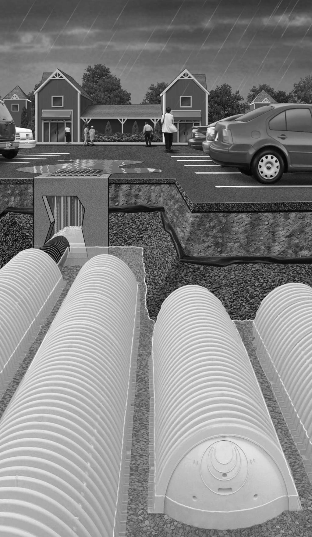
1 Installation Instructions StormTech Chamber System for Stormwater Management
2 Before You Begin REQUIRED MATERIALS AND EQUIPMENT LIST Acceptable 3 4" 2" (20-50 mm) clean, crushed, angular stone per Tables 4 & 5 on page 10 Acceptable fill materials per Table 5 on page 10 Filter fabric StormTech end caps StormTech chambers Reciprocating saw or router (to custom cut end cap holes) OSHA compliance Stone bucket Tracked excavator Transit or laser Vibratory roller with maximum gross vehicle weight of 12,000 lbs and a maximum dynamic force of 20,000 lbs Requirements for System Installation 1 StormTech LLC requires installing contractors to use and understand StormTech s most current installation instructions prior to beginning system installation. All illustrations and photographs are examples of typical situations. Actual designs may vary. Be sure to follow the engineer s drawings. 2 StormTech offers installation consultations to installing contractors. Contact StormTech at least 30 days prior to system installation to arrange a pre-installation consultation. Our representatives can answer questions, address comments and provide information about the StormTech chamber system s installation requirements. Call or visit to receive the most current version of our installation instructions. 3 Contact local underground utility companies prior to construction. 4 All StormTech system designs must be certified by a registered professional engineer. 5 StormTech s requirements for systems with a pavement design (asphalt, concrete pavers, etc.): Minimum cover is 18" (457 mm) not including pavement; maximum cover is 96" (2438 mm) including pavement design. For installations that do not include pavement, where rutting from vehicles may occur, minimum required cover is 24" (610 mm), maximum cover is 96" (2438 mm). 6 The contractor must report any discrepancies with the system subgrade soil s bearing capacity to the design engineer. 7 Check chambers for shipping damage prior to installation. Units that have been damaged must not be installed. Contact StormTech immediately upon discovery of any damage. 8 Filter fabric must be used as indicated in the engineer s drawings. 9 To maintain row separation distances and prevent chamber displacement, place stone between chamber rows and around perimeter as required by the most current version of StormTech s Installation Instructions. 10 Backfilling of the chamber system must be in accordance with the most current version of StormTech's Installation Instructions. 11 The contractor must refer to StormTech s Installation Instructions for Tables of Acceptable Vehicle Loads at various depths of cover. This information is also available at The contractor is responsible for preventing vehicles that exceed StormTech s requirements from traveling across or parking over the stormwater system. Temporary fencing, warning tape and appropriately located signs are commonly used to prevent unauthorized vehicles from entering sensitive construction areas. 12 The contractor must apply erosion and sediment control measures to protect the stormwater system during all phases of site construction per local codes and design engineer s specifications. 2 Call StormTech at for technical and product information or visit


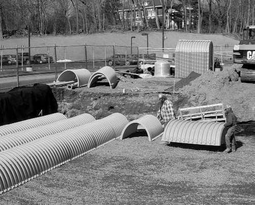
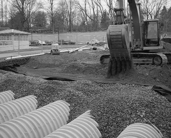
3 Requirements for System Installation 13 StormTech products must be designed and installed in accordance with StormTech s minimum requirements. Failure to do so will void the limited warranty. 15 For installation instructions for any additional structures or fittings not covered in these instructions, contact StormTech at StormTech product warranty is limited. See current product warranty for details. To acquire a copy call StormTech at or visit Requirements for Excavating and Preparing the Site Left side of bed being prepared while right side is concurrently installed. Filter fabric and underdrains installed. 1 Excavate and level the designated area. Be sure to excavate at least one extra foot around the perimeter to allow for proper fit and adequate compaction. 2 Excavation must be free of standing water. Dewatering measures must be taken if required. Positive drainage of the excavation must be maintained. 3 Prepare the chamber bed s subgrade soil as outlined in the engineer s drawings. 4 Place AASHTO M288 Class 2 non-woven filter fabric over the prepared subgrade soils. Table 3 lists suitable geotextiles. The filter fabric must overlap at least 2 feet (610 mm) where the fabric edges meet. 5 Place AASHTO M288 Class 2 non-woven filter fabric around the perimeter of the excavated bed as specified in the engineering drawings. NOTE: (Fabric is required over the top of the entire chamber system after the 6" (152 mm) of stone is placed over chambers.) 6 Perforated pipe outlet underdrains may be designed within the one foot stone perimeter. Install perforated pipe outlet underdrains as required by the engineer s drawings. 7 Place acceptable 3 4-2" (20-50 mm) clean, crushed, angular stone foundation material over the entire bottom surface of the bed (see Tables 4 & 5 for stone requirements). Refer to the engineer s drawings for subgrade soil preparation and required stone foundation thickness. 8 Compact the stone using a vibratory roller with its full dynamic force applied to achieve a flat surface. Call StormTech at for technical and product information or visit 3


 clear space between chamber rows.")
4 Requirements for Assembling Inlet Pipes NOTE: Depending on the system s design, it may be advantageous to lay out the inlet and outlet pipe systems prior to forming the bed of chambers. Cut an opening for the distribution pipe. 1 Temporarily layout the header/manifold system according to the engineer s drawings. 2 Stone foundation scour control measures such as splash pads, riprap, or geotextiles may be required by the design engineer. Locate and install scour control measures per engineer s drawings if required. 3 Set first chamber of each row aligned with their inlet pipes if applicable. A minimum 6" (152 mm)* clear spacing, measured between feet, is required between adjacent rows. Separate chambers and inlet fittings as necessary to maintain 6" (152 mm) clear space between chamber rows. 4 With a reciprocating saw, cut an opening for the inlet piping in the applicable endcaps at the specified invert height. NOTE: Inlet pipe openings may be cut anywhere on an endcap. To do this, take a short length of pipe and use a marker to draw an outline of the pipe on the endcap at the correct height. 5 Insert the distribution pipes into the endcaps. 6 Once chamber spacing requirements are met, the header/ manifold system may be permanently assembled ( mm) reducers installed to stay within the 25 (635 mm) maximum OD limit for the SC-740. *6" (152 mm) is the minimum recommended spacing. A wider spacing may be required as indicated on the engineer s drawings. Requirements for Installing the Chambers 1 To begin building the chamber bed, orient the chambers so the end labeled Build Rows in This Direction is closest to the bed s edge and the arrows point in the direction of the build. Maintain a minimum 6" (152 mm) separation between chamber rows (measurement taken from the foot of chambers). Maintain a minimum of 6" (152 mm) between chamber feet. 4 Call StormTech at for technical and product information.


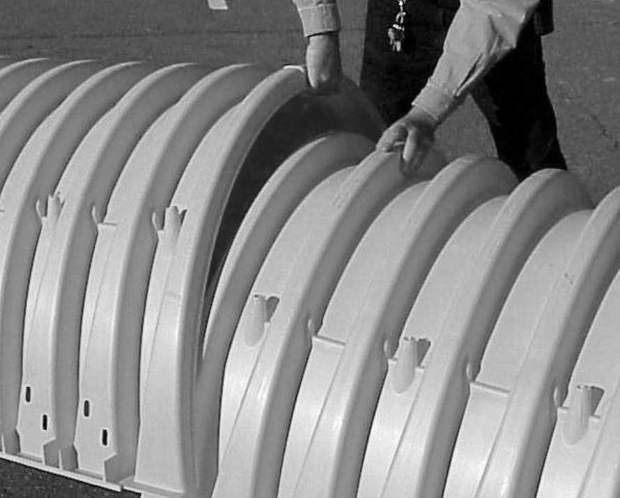
5 Requirements for Joining the Chambers Construct the chamber bed by overlapping the chamber s end corrugations. Although not visible to the eye, a chamber s end corrugations are sized differently to allow for an overlapping joint. To ensure proper joint fit, orient all chambers in the bed with their arrows pointing in the direction of the build. The chamber s overlapping feet are a distinguishing feature to help quickly identify the proper chamber orientation. 1 Construct the chamber bed by joining the chambers lengthwise in rows. Attach chambers by overlapping the end corrugation of one chamber onto the end corrugation of the last chamber in the row. Be sure that chamber placement does not exceed the reach of the construction equipment used to place the stone. NOTE: Do not overlap more than one corrugation. Requirements for Attaching the End Caps 1 Lift the end of the chamber a few inches off the ground. With the curved face of the end cap facing outward, place the end cap into the chamber s end corrugation. NOTE: End caps are required only at the beginning and the end of each row of chambers. Lift the end of the chamber and place the end cap into the end corrugation. Requirements for Placing Stone Over the Chambers A minimum of three feet (914 mm) cover is required for trucks to dump stone. (See page 7, Section 4) Angular stone meeting the specifications in Tables 4 & 5 and Figure 1 on page 10 may be placed over the chambers with an excavator, pushed with a dozer or walked in with a stone conveyer boom. Each method has benefits and limitations. These three processes will be explained separately, however there are some common requirements for each: The 6" (152 mm) minimum clear spacing must always be maintained between adjacent StormTech s chamber rows; and, construction vehicle loads must not exceed the requirements of Tables 1 & 2 on page 9. Call StormTech at for technical and product information. 5


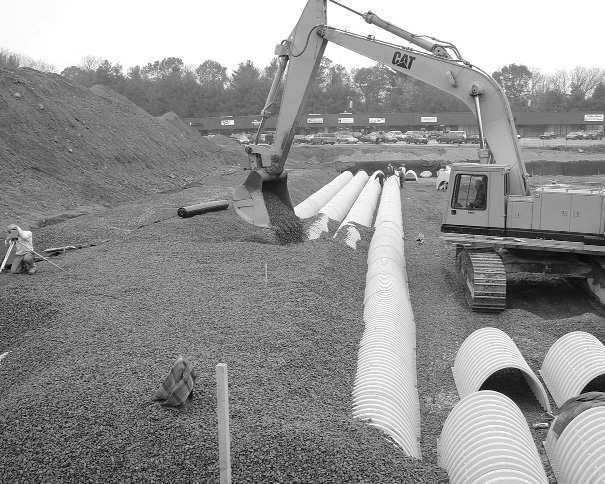
6 Requirements for Placing Stone with an Excavator Carefully ladle 3/4 2 (20-50 mm) clean, crushed, angular stone over the centerline of the chamber row. Placing stone with an excavator is currently the most common method of placing stone over StormTech s chambers. Its biggest limitation is the reach of the excavator arm. For larger beds it is common practice to work across a bed by joining only a few rows of chambers and placing their angular stone embedment, the filter fabric and soil fill before moving onto the next few rows. A bed may be built either parallel to or perpendicular to the chamber row s direction with this process. The excavator typically works inside the excavation, leading the way across the bed. It is also possible for the excavator to work at grade over the recently placed chambers following the build across. If this process is done it is required that the depth of cover between tops of chambers and the excavator s tracks be the minimum required by Tables 1 & 2 on page 9. 1 Anchor chambers by carefully ladling angular stone directly over the centerline of the chambers. Evenly distribute stone to minimize chamber movement while maintaining row separation distances. 2 After chambers are anchored, continue to place the stone, surrounding the chambers and filling the perimeter areas to a minimum of 6" (152 mm) over the top of chambers. Do not drive equipment over the chambers without minimum cover required by Tables 1 & 2 on page 9. 3 Repeat steps 1 & 2 until all the chambers are laid to the dimensions of the engineer s drawing. Requirements for Pushing Stone with a Dozer Low ground pressure track vehicle pushing stone parallel with rows. A dozer may be used to push the angular stone embedment into place over the chambers. There are some strict requirements for this process. 1 All stone must be pushed in a direction parallel with the rows of chambers. Pushing stone perpendicular across chamber rows may cause the chambers to move, possibly reducing the required 6" (152 mm) minimum spacing between rows. 2 Always maintain the required cover between the tops of chambers and the dozer tracks, per Table 2 on page 9. The contractor must check Table 2 on page 9 to determine if their construction vehicles can be used over the chamber bed. 6 Call StormTech at for technical and product information or visit
 3 The angular stone cover height should never differ by more than 2 feet (610 mm) over adjacent chambers unless there is a minimum cover of 3 feet (914 mm) over the chambers.")
 of cover over the")
7 Requirements for Pushing Stone with a Dozer (cont.) 3 The angular stone cover height should never differ by more than 2 feet (610 mm) over adjacent chambers unless there is a minimum cover of 3 feet (914 mm) over the chambers. Stone should be pushed in small piles and spread evenly to prevent movement of chamber rows. 4 Full dump trucks must not drive over or dump stone over StormTech chambers unless Requirements Placing Stone with a Telescoping Conveyer Boom there is a minimum of 3 feet (914 mm) of cover over the chambers. It is convenient for truckers to dump stone as close to the dozer as practical, however a full truck is often the heaviest load on a construction site. Raising the body to dump stone significantly increases the rear wheel loads. Three feet (914 mm) of cover is the minimum requirement for dumping stone over StormTech chambers. Placing stone with the conveyor boom extended. Telescoping aggregate conveyer trucks are becoming increasingly popular at construction sites. Their use can save a significant amount of time, money and free up other heavy equipment for other uses. They are only limited by the range of the boom. Typical trucks have a boom range between 50 to 130 feet (9-15 m). Booms can convey up to 360 cubic feet (110 m 3 ) of stone per hour. 1 Anchor chambers by carefully ladling angular stone directly over the centerline of the chambers. Evenly distribute stone to minimize chamber movement while maintaining row separation distances. 2 After chambers are anchored, continue to place the stone, surrounding the chambers and filling the perimeter areas to a minimum of 6" (152 mm) over the top of chambers. Do not drive equipment over the chambers without minimum cover required by Tables 1 & 2 on page 9. 3 Repeat steps 1 & 2 above until all the chambers are laid to the dimensions of the engineer s drawings. Evenly distributing stone with conveyor boom. Call StormTech at for technical and product information or visit 7

 of fill material must meet the requirements of Table 5 on page 10.")

8 Requirements for Backfilling the System 1 Place the required angular stone over the entire bed area as described in previous sections. 2 Cover the entire installation area with AASHTO M288 Class 2 non-woven filter fabric. Take the fabric from the perimeter and lay it over the top of the stone. The filter fabric must overlap at least 2 feet (610 mm) where the edges of the fabric meet. Roll out filter fabric. Backfill the bed using an acceptable fill material. Continue to backfill the chamber bed. 3 The first 12 inches (305 mm) of fill material must meet the requirements of Table 5 on page 10. Backfill over the top of the filter fabric in lifts that do not exceed 6 inches (152 mm). Distribute the fill with a construction vehicle that meets the maximum wheel loads or ground pressure limits specified in Tables 1 & 2 on page 9. 4 Compact each lift of backfill as specified in the engineer s drawings. StormTech requires compacting to a minimum of 95% of the Standard Proctor density. Use a walk-behind or vibratory roller not to exceed a maximum gross vehicle weight of 12,000 lbs and a maximum dynamic force of 20,000 lbs. 5 Continue to backfill over the chamber bed in 6" (152 mm) maximum lifts until the specified grade is achieved. StormTech s cover requirements are 18" (457 mm) minimum and 96" (2438 mm) maximum over the top of the chambers. For pavement sub-base or special fill requirements, see engineer s drawings. The backfill height differential should never differ by more than 2 feet (610 mm) over adjacent chambers. Minimum cover heights must be met before vehicles are allowed on top of the system. Large rocks and organic matter such as roots, stumps, etc. must not be part of the backfill material. Refer to Table 5 on page 10 for Acceptable Cover Materials or contact the design engineer for approved fill types. 8 Call StormTech at for technical and product information.
9 Acceptable Vehicle Loads TABLE 1 Maximum Allowable Axle Loads for Wheeled Vehicles at Various Cover Depths Fill Depth (in. over chamber) Max. Axle Load (lbs) 6 8, , with pavement 32, without pavement 32,000 NOTE: 36" (914 mm) of cover over the chambers is required for full dump truck travel and dumping. See instruction number 4 on page 7. TABLE 2 Maximum Allowable Ground Pressures for Various Vehicle Track Widths and Fill Depths Fill Depth (in. over chamber) Track Width (in.) Max. Ground Pressure (PSF)* * Ground pressure is vehicle operating weight divided by total truck contact area for both tracks. Call StormTech at or visit for examples of allowable tracked vehicles. Acceptable Geotextiles TABLE 3 Some Suitable Geotextiles Manufacturer AASHTO M288 Class 2 Non-Woven* AASHTO M288 Class 1 Woven** Amoco Fabrics and Fibers (Part of BP) ProPex 4506, ProPex 4508, ProPex 4551, ProPex 2006, ProPex 2016, ProPex 2004 ProPex 4552, ProPex 4553 Belton Industries Beltech 315 Style 883 Carthage Mills FX-60HS, FX-80HS FX-66 Contech Const. Products C-70NW GSE Lining Technology NW6, NW8 Maccaferri MacTex MX245, MacTex MX275 Mirafi Const. Products Mirafi 160N, Mirafi 180N Mirafi 600X, Filterweave 403, Filterweave 404 Geolon HP570, Geolon HP665, Geolon HP770 Pavco - Amanco NT 3000, NT 4000 TR 4000 SI Geosolutions Geotex 601, Geotex 801 Geotex 315ST TNS Advanced Tech. R 060, R070, R 080, R100 M 403 US Fabrics US 205NW-C US 315 Webtec TeraTex N06, TeraTex N08 TeraTex HD *AASHTO M288 Class 2 Non-Woven Geotextile Application: 1. Separation layer between angular stone cover and fill to prevent fines intrusion. 2. Filter layer over the chambers of the Stormtech Isolator Row to prevent fines migration out of row while maintaining adequate hydraulic flows. **AASHTO M288 Class 1 Woven Geotextile Application: Stabilization layer for the angular stone foundation of the StormTech Isolator Row to prevent scouring of the stone base during the JetVac maintenance procedure, modest hydraulic flows maintained. Call StormTech at for technical and product information. 9
10 Acceptable Fill Materials TABLE 4 Criteria for Acceptable 3/4 2" (20-50 mm) Clean, Crushed, Angular Stone Clean Crushed Stone Description Criteria Acceptable Angular Stones have sharp edges and relatively plane sides with unpolished surfaces Subangular TABLE 5 Acceptable Fill Materials Stones are similar to angular description but have rounded edges Unacceptable Subrounded Stones have nearly plane sides but have well-rounded corners and edges Rounded NOTE: See A & B of Table 5 for additional angular stone requirements. Stones have smoothly curved sides and no edges Material Location Description AASHTO M43 AASHTO M145 Compaction/Density Designation Designation Requirement D Fill Material from 18" (457 mm) Any soil/rock materials, native soils N/A N/A Prepare per engineer s plans. Paved to grade above chambers or per engineer s plans. Check plans installations may have stringent for pavement subgrade requirements. material and preparation requirements. C Fill Material for 6" to 18" Granular well-graded soil/ 3, 357, 4, 467, A-1 Compact in 6" (152 mm) lifts to a min. ( mm) elevation above aggregate mixtures, <35% fines 5, 56, 57, 6, A-2 95% Standard Proctor density. chambers [24" (610 mm) 67, 68, 7, 78, 8, A-3 Roller gross vehicle weight not for unpaved installations] 89, 9, 10 to exceed 12,000 lbs. Dynamic force not to exceed 20,000lbs. B Embedment Stone surrounding Clean, angular stone with the 3, 357, 4, 467 N/A No compaction required. and to a 6" (152 mm) elevation majority of particles between 3/4-2 5, 56, 57 above Chambers (20-50 mm) A Foundation Stone Clean, angular stone with majority of 3, 357, 4, 467 N/A Plate compact or roll to achieve a below Chambers particles between 3/4-2 (20-50 mm) 5, 56, 57 95% Standard Proctor Density. PLEASE NOTE: The listed AASHTO designations are for gradations. The stone must also be clean, crushed angular. For example, the stone must be specified as clean, crushed, angular No. 4. stone. FIGURE 1 Fill Material Locations PAVEMENT (PER ENGINEER'S DRAWINGS) D C B * TO BOTTOM OF FLEXIBLE PAVEMENT. FOR UNPAVED INSTALLATIONS WHERE RUTTING FROM VEHICLES MAY OCCUR, INCREASE COVER TO 24" (610 mm) 18" (460 mm)* MIN. 6" (150 mm) MIN. 96" (2440 mm) MAX. A DEPTH OF STONE TO BE DETERMINED BY DESIGN ENGINEER 6" (150 mm) MIN. AASHTO M288 CLASS 2 NON-WOVEN GEOTEXTILE ALL AROUND ANGULAR STONE 10 Call StormTech at for technical and product information or visit
11 Requirements for Assembling the StormTech Isolator Row The StormTech Isolator Row is a row of chambers designed to trap sediments in stormwater and provide access for inspection and maintenance. The StormTech Isolator Row is a row of StormTech chambers surrounded with two types of filter fabric: a strip of AASHTO M288 Class 1 woven geotextile laid down between the foundation stone and the row of chambers, and; a strip of AASHTO M288 Class 2 non-woven geotextile draped over the row of chambers. Note that the tough, woven geotextile is required on the bottom to provide a durable surface for future maintenance procedures. See Table 3 on page 9 for a list of Acceptable Geotextiles. Isolator Row configurations are custom designed for each project and may vary from project to project. The actual layout shall be installed according to the engineer s drawings and these installation instructions. 1 The Isolator Row is designed with an access manhole just upstream of the Isolator Row inlet. It is recommended that the access manhole be installed prior to assembling the Isolator Row. The access manhole generally contains a high flow weir that diverts the first flows to the Isolator Row. Flows that exceed the design capacity of the Isolator Row over top the bypass weir and discharge to the distribution manifold. For weir construction details, see the engineer's drawings. 2 Installation of the Isolator Row may begin after the stone foundation is laid and prepared per the engineer s drawings. See Requirements for Excavating and Preparing the Site in this manual. 3 Layout the Isolator Row. For detailed layout dimensions, see the engineer's drawings or StormTech layout details for the project. 4 Roll out a continuous strip of AASHTO M288 Class 1 woven geotextile over the angular stone foundation so the open bottom area of Isolator Row chambers will be completely covered. There must not be any seams in the woven geotextile. Table 3 lists acceptable woven geotextiles. See Figure 2 for the width of the fabric strip required. 5 Form the Isolator Row by joining Stormtech chambers centered over the woven geotextile. See Requirements for Joining Chambers in this manual. 6 A short segment of pipe is typically used to connect the manhole to the Isolator Row through a StormTech endcap. See Requirements for Attaching Inlet Pipes in this manual for direction on connecting the pipe to the endcap. 7 Drape a strip of AASHTO M288 Class 2 non-woven geotextile over the row of chambers. This is the same type of non-woven filter fabric used as a separation layer around the angular stone of a StormTech system. A single continuous piece is preferred. Table 3 lists suitable non-woven geotextiles. 8 See Requirements for Placing Stone and Requirements for Backfilling the System in this manual for directions on completing the Isolator Row installation. FIGURE 2 StormTech Isolator Row Detail INSPECTION PORT LOCATION PER ENGINEER'S DRAWING COVER ENTIRE ROW WITH AASHTO M288 CLASS 2 NON-WOVEN GEOTEXTILE SC-740 8' (2.4 m) WIDE STRIP SC-310 5' (1.5 m) WIDE STRIP STORMTECH ENDCAP CATCH BASIN OR MANHOLE SUMP DEPTH BY DESIGN ENGINEER WOVEN GEOTEXTILE THAT MEETS AASHTO M288 CLASS 1 REQUIREMENTS, BETWEEN STONE BASE AND CHAMBERS SC-740 5' (1.5 m) WIDE STRIP SC-310 4' (1.2 m) WIDE STRIP Call StormTech at for technical and product information. 11
12 STANDARD LIMITED WARRANTY OF STORMTECH LLC ("STORMTECH"): PRODUCTS (A) (B) (C) (D) (E) This Limited Warranty applies solely to the StormTech chambers and endplates manufactured by StormTech and sold to the original purchaser (the Purchaser ). The chambers and endplates are collectively referred to as the Products. The structural integrity of the Products, when installed strictly in accordance with StormTech's written installation instructions at the time of installation, are warranted to the Purchaser against defective materials and workmanship for one (1) year from the date of purchase. Should a defect appear in the Limited Warranty period, the Purchaser shall provide StormTech with written notice of the alleged defect at StormTech s corporate headquarters within ten (10) days of the discovery of the defect. The notice shall describe the alleged defect in reasonable detail. StormTech agrees to supply replacements for those Products determined by StormTech to be defective and covered by this Limited Warranty. The supply of replacement products is the sole remedy of the Purchaser for breaches of this Limited Warranty. StormTech s liability specifically excludes the cost of removal and/or installation of the Products. THIS LIMITED WARRANTY IS EXCLUSIVE. THERE ARE NO OTHER WARRANTIES WITH RESPECT TO THE PRODUCTS, INCLUDING NO IMPLIED WARRANTIES OF MERCHANTABILITY OR OF FITNESS FOR A PARTICU- LAR PURPOSE. This Limited Warranty only applies to the Products when the Products are installed in a single layer. UNDER NO CIRCUMSTANCES, SHALL THE PRODUCTS BE INSTALLED IN A MULTI-LAYER CONFIGURATION. No representative of StormTech has the authority to change this Limited Warranty in any manner or to extend this Limited Warranty. This Limited Warranty does not apply to any person other than to the Purchaser. (F) Under no circumstances shall StormTech be liable to the Purchaser or to any third party for product liability claims; claims arising from the design, shipment, or installation of the Products, or the cost of other goods or services related to the purchase and installation of the Products. For this Limited Warranty to apply, the Products must be installed in accordance with all site conditions required by state and local codes; all other applicable laws; and StormTech s written installation instructions. (G) THE LIMITED WARRANTY DOES NOT EXTEND TO INCI- DENTAL, CONSEQUENTIAL, SPECIAL OR INDIRECT DAMAGES. STORMTECH SHALL NOT BE LIABLE FOR PENALTIES OR LIQUIDATED DAMAGES, INCLUDING LOSS OF PRODUCTION AND PROFITS; LABOR AND MATERIALS; OVERHEAD COSTS; OR OTHER LOSS OR EXPENSE INCURRED BY THE PURCHASER OR ANY THIRD PARTY. SPECIFICALLY EXCLUDED FROM LIMIT- ED WARRANTY COVERAGE ARE DAMAGE TO THE PRODUCTS ARISING FROM ORDINARY WEAR AND TEAR; ALTERATION, ACCIDENT, MISUSE, ABUSE OR NEGLECT; THE PRODUCTS BEING SUBJECTED TO VEHICLE TRAFFIC OR OTHER CONDITIONS WHICH ARE NOT PERMITTED BY STORMTECH S WRITTEN SPECIFICATIONS OR INSTALLATION INSTRUCTIONS; FAILURE TO MAINTAIN THE MINIMUM GROUND COV- ERS SET FORTH IN THE INSTALLATION INSTRUC- TIONS; THE PLACEMENT OF IMPROPER MATERIALS INTO THE PRODUCTS; FAILURE OF THE PRODUCTS DUE TO IMPROPER SITING OR IMPROPER SIZING; OR ANY OTHER EVENT NOT CAUSED BY STORMTECH. THIS LIMITED WARRANTY REPRESENTS STORMTECH S SOLE LIABILITY TO THE PURCHASER FOR CLAIMS RELATED TO THE PRODUCTS, WHETHER THE CLAIM IS BASED UPON CONTRACT, TORT, OR OTHER LEGAL THEORY. 20 Beaver Road, Suite 104 Wethersfield Connecticut fax fax StormTech products are covered by one or more of the following patents: U.S. Patents: 5,401,459; 5,511,903; 5,716,163; 5,588,778; 5,839,844; Canadian Patents: 2,158,418 Other U.S. and Foreign Patents Pending Printed in U.S.A. Copyright. All rights reserved. StormTech LLC, 2006 S
Installation Instructions. StormTech Chamber System for Stormwater Management
 SC-310/SC-740 Chambers Installation Instructions StormTech Chamber System for Stormwater Management Before You Begin REQUIRED MATERIALS AND EQUIPMENT LIST Acceptable nominal 3 4" 2" (19-51 mm) clean, crushed,
StormTech Construction Guide
 A division of StormTech solid end caps and pre-cored end caps StormTech chambers StormTech manifolds and fittings Acceptable fill materials per Table 1 Woven and non-woven geotextiles 80-7 DC REQUIRED
StormTech Construction Guide
 REQUIRED MATERIALS AND EQUIPMENT LIST An 80-7 DC 0/ 74 C/S 10-3 SC StormTech Construction Guide company ~ Bc^a\CTRW b^[xs T]S RP_b P]S _at R^aTS T]S RP_b ~ Bc^a\CTRW RWP\QTab ~ Bc^a\CTRW \P]XU^[Sb P]S
StormTech Construction Guide
 Stormtech MC-3500 Construction Guide 12/31/14 11:18 AM Page 1 M /M 00 35 C- A division of REQUIRED MATERIALS AND EQUIPMENT LIST 00 45 C- StormTech Construction Guide Detention Retention Water Quality Acceptable
StormTech Construction Guide
 M /M 00 35 C- A division of REQUIRED MATERIALS AND EQUIPMENT LIST 00 45 C- StormTech Construction Guide Detention Retention Water Quality Acceptable fill materials per Table 1 Woven and non-woven geotextiles
StormTech Construction Guide An company
 SC-160LP StormTech Construction Guide An company REQUIRED MATERIALS AND EQUIPMENT LIST IMPORTANT NOTES: A. This installation guide provides minimum requirements for proper installation of chambers. Non-adherence
Installation Instructions. Triton Stormwater Solutions Chamber System for Stormwater Management
 Installation Instructions Triton Stormwater Solutions Chamber System for Stormwater Management Revised June/2015. Supersedes all previous installation manuals. Triton Stormwater Solutions Chamber System
StormTech SC-310 Chamber (not to scale) Nominal Chamber Specifications
 Nominal Chamber Specifications") StormTech SC-310 Chamber Designed to meet the most stringent industry performance standards for superior structural integrity while providing designers with a cost-effective method to save valuable land
StormTech SC-310 Chamber Designed to meet the most stringent industry performance standards for superior structural integrity while providing designers with a cost-effective method to save valuable land
Installation Instructions - Retention. Triton Stormwater Solutions Chamber System for Stormwater Management
 TM Installation Instructions - Retention Triton Stormwater Solutions Chamber System for Stormwater Management Revised 02/13. Supersedes all previous installation manuals. Triton Stormwater Solutions Chamber
Installation Instructions. Triton Stormwater Solutions Chamber System for Stormwater Management
 Installation Instructions Triton Stormwater Solutions Chamber System for Stormwater Management Revised March/2018. Supersedes all previous installation manuals. Triton Stormwater Solutions Chamber System
StormTech DC-780 Chamber
 StormTech DC-780 Chamber DC-780 Chamber Designed to meet the most stringent industry performance standards for superior structural integrity while providing designers with a costeffective method to save
Design Manual StormTech. Chamber Systems for Stormwater Management
 Design Manual StormTech Chamber Systems for Stormwater Management Table of Contents 1.0 Introduction...2 2.0 Product Information...3 3.0 Structural Capabilities...6 4.0 Foundation for Chambers...8 5.0
MC-3500 & MC-4500 Design Manual StormTech Chamber Systems for Stormwater Management
 StormTech MC-3500 Chamber MC-3500 & MC-4500 Design Manual StormTech Chamber Systems for Stormwater Management THE MOST ADVANCED NAME IN WATER MANAGEMENT SOLUTIONS Call StormTech at 860.52.88 or 888.82.264
MC-3500 and MC-4500 Design Manual
 MC-3500 / MC-4500 MC-3500 and MC-4500 Design Manual StormTech Chamber Systems for Stormwater Management Table of Contents 1.0 Product Information...2 2.0 Foundations for Chambers...8 3.0 Required Materials/Row
Stormwater Retention, Detention, Reuse and Conveyance.
 Installation Manual Stormwater Retention, Detention, Reuse and Conveyance www.stormchambers.com Before Your Stormchambers Arrive 1. StormChambers will arrive either on a flat bed trailer or in an enclosed
Design Manual. StormTech. Chamber Systems for Stormwater Management
 SC-310/SC-740 Chambers Design Manual StormTech Chamber Systems for Stormwater Management Table of Contents 1.0 Introduction...2 2.0 Product Information...3 3.0 Structural Capabilities...6 4.0 Foundation
Model Number. Job Number. StormChamber. Installation with liner for Retention Manual.
 Model Number Job Number StormChamber Installation with liner for Retention Manual www.allpumps.com.au Before your StormChambers arrive When your StormChambers arrive 1. StormChambers will arrive either
Contactor & Recharger
 Contactor & Recharger Septic Chambers 2009 Installation Guide Book CULTEC Septic Chambers CULTEC Chambers: The New Standard in Leachfields The CULTEC Contactor and Recharger chambers are the alternative
Installation Guidelines
 815 NE 172 nd Avenue Vancouver, WA 98684 877-694-0141 Installation Guidelines Installation steps include job planning, layout, excavating and preparing the soil subgrade, applying geotextiles (optional),
BMP 6.4.4: Infiltration Trench
 BMP 6.4.4: Infiltration Trench An Infiltration Trench is a leaky pipe in a stone filled trench with a level bottom. An Infiltration Trench may be used as part of a larger storm sewer system, such as a
1.0 Stormtank Assembly Basin Excavation Sub Grade Requirements Leveling Bed Installation... 3
 Table of Contents 1.0 Stormtank Assembly... 1 2.0 Basin Excavation... 2 3.0 Sub Grade Requirements... 2 4.0 Leveling Bed Installation... 3 5.0 Stormtank Module Placement... 3 5.0 Stormtank Module Placement
Handling and Installation Instructions
 Handling and Installation Instructions SUPERTANK Water Reclamation Solutions, LLC Unloading and Handling NOTE: It is the responsibility of the installer to follow OSHA safety guidelines during the installation,
PERMEABLE INTERLOCKING PAVERS
 PERMEABLE INTERLOCKING PAVERS PART 1 - GENERAL 1.01 SECTION INCLUDES A. Subgrade Preparation B. Placement of Storage Aggregate C. Placement of Filter Aggregate D. Placement of Bedding Course E. Placement
Rethinking Water Management Systems
 Rethinking Water Management Systems Table of Contents Introduction... 1 PIPE-R Reservoir System Installation Procedure... 2 Product Delivery and Assembly... 2 Site Layout and Excavation... 3 Preparation
Inlet Protection. Fe= (Depends on soil type)
") 3.4 DESIGN CRITERIA: KEY CONSIDERATIONS Evaluate drainage patterns to ensure inlet protection will not cause flooding of roadway, property or structures Never block entire inlet opening Size according
3.4 DESIGN CRITERIA: KEY CONSIDERATIONS Evaluate drainage patterns to ensure inlet protection will not cause flooding of roadway, property or structures Never block entire inlet opening Size according
PRODUCT CATALOG MC-4500 SC-740 MC-3500 THE MOST ADVANCED NAME IN WATER MANAGEMENT SOLUTIONS
 PRODUCT CATALOG MC-4500 MC-3500 SC-740 THE MOST ADVANCED NAME IN WATER MANAGEMENT SOLUTIONS STORMTECH SUBSURFACE STORMWATER MANAGEMENT TABLE OF CONTENTS Product Features and Benefits... 5 SC-160LP...6
STORMCAPTURE. Installation Manual
 STORMCAPTURE Installation Manual Introduction Site Preparation Delivery & Installation LinkSlabs Backfill Introduction StormCapture (shown in Figure 1) is a total stormwater management system. The highly-configurable
DETENTION, RETENTION AND RECHARGE STRUCTURES
 DETENTION, RETENTION AND RECHARGE STRUCTURES Introduction Foundation, trenchwall, bedding and backfill considerations for multiple barrel detention systems are not unlike those for conventional CSP installations.
CONSTRUCTION STANDARDS SECTION CS 3 TRENCH FOUNDATION, BEDDING AND BACKFILL
 CONSTRUCTION STANDARDS SECTION CS 3 TRENCH FOUNDATION, BEDDING AND BACKFILL CS 3-01 GENERAL: A. The foundation, bedding and backfill for all trenches shall conform with the requirements of the City Standard
SECTION MECHANICALLY STABILIZED EARTH RETAINING WALLS
 SECTION 13100 MECHANICALLY STABILIZED EARTH RETAINING WALLS PART 1 -- GENERAL 1.01 THE REQUIREMENT A. Includes all labor, material, equipment, testing and submittals required to design and complete construction
Product Catalog. company SC-310 DC-780 SC-740 MC-3500 MC-4500
 An company SC-310 DC-780 SC-740 MC-3500 Product Catalog This catalog is not intended to provide requirements for design or installation of StormTech chambers. Refer to the appropriate StormTech Design
Subsurface Sport Turf Applications
 ADS Terms and Conditions of Sale are available on the ADS website, www.ads-pipe.com Advanced Drainage Systems, the ADS logo, and the Green Stripe, are registered trademarks of Advanced Drainage Systems,
HUITEX GEOCELL INSTALLATION MANUAL
 Table of Contents 1 Site Preparation 2 Installation for the Retaining Wall 2.1 Base Preparation 2.2 Footing Installation 2.3 Placement of the Drainage System 2.4 Placement of the HUITEX Geocell panels
R-TANK SPECIFICATIONS
 TECHNICAL STORMWATER MANAGEMENT R-TANK SPECIFICATIONS PART 1 GENERAL 1.01 Related Documents A. Drawings, technical specification and general provisions of the Contract as modified herein apply to this
MACHINE-LAY Installation Manual
 MACHINE-LAY Installation Manual PaveDrain Installation Manual Table of Contents Section 1: Base Preparation (pages 3 6) Section 2: Machine-Lay PaveDrain Blocks (pages 8 11) Section 3: Edge Restraints (pages
PaveDrain Installation Manual. Table of Contents. Hand-Placement of individual PaveDrain Units. PaveDrain End Cap
 Installation Manual PaveDrain Installation Manual Table of Contents Section 1: Base Preparation Section 2: Hand-Placement of individual PaveDrain Units Section 3: Mattress Installation Section 4: PaveDrain
Base Course Design and Construction
 Part I General A. This information is to be used as a guideline in construction a dynamic aggregate base and drainage system. Project conditions may vary based on overall scope of work and location. Any
SECTION 19 - TRENCH EXCAVATION, BEDDING AND BACKFILL TABLE OF CONTENTS
 SECTION 19 - TRENCH EXCAVATION, BEDDING AND BACKFILL TABLE OF CONTENTS Section Page 19-1 TRENCH EXCAVATION... 19.1 19-1.01 Exploratory Excavation... 19.1 19-1.02 Trench Width... 19.1 19-1.02.A Storm Drain
SECTION PERMEABLE INTERLOCKING CONCRETE UNIT PAVEMENT
 SECTION 32 14 13 19 PERMEABLE INTERLOCKING CONCRETE UNIT PAVEMENT SECTION 32 14 13 19 PERMEABLE INTERLOCKING CONCRETE UNIT PAVEMENT PART 1 - GENERAL 1.1 SUMMARY A. Section Includes: 1. Permeable Articulating
On-Site Leaching Chamber Specifications & Features. Design & Installation Manual New York
 On-Site Leaching Chamber Specifications & Features Design & Installation Manual New York 1 This manual provides general design and installation information for use of Arc plastic leaching chambers in the
SEPA Environmental Checklist Mercer Island Center for the Arts. Attachment F Geotechnical Supplemental Memo
 SEPA Environmental Checklist Mercer Island Center for the Arts Attachment F Geotechnical Supplemental Memo January 2017 MEMORANDUM DATE: May 6, 2015 TO: FROM: RE: CC: Katie Oman, Mercer Island Center for
Appendix B.2. Construction Specifications for Infiltration Practices
 Appendix B.2 Construction Specifications for Infiltration Practices B.2.A Infiltration Trench General Notes and Specifications An infiltration trench may not receive run-off until the entire contributing
VERSA-Green TM Plantable Retaining Wall System
 www.versa-lok.com VERSA-Green TM Plantable Retaining Wall System VERSA-GREEN INSTALLATION The VERSA-Green Plantable Wall System from VERSA-LOK is truly the greenest retaining wall available. It combines
COUNTY BLOCK. Construction Guidelines on County Block Steps. Special Considerations When Building Steps. Natural Beauty Absolute Strength
 Construction Guidelines on County Block Limits of Liability This County Block Installation Guide provides general information about the product, including installation procedures, technical and engineering
STORMWATER DETENTION SYSTEM INSTALLATION GUIDE
 STORMWATER DETENTION SYSTEM INSTALLATION GUIDE 1 PRE-CONSTRUCTION CHECKLIST Tools You ll Need o Laser or Transit o Measuring Tape (long enough to mark R-Tank footprint) o Razor Knife o Screw Driver / Nut
STORMWATER DETENTION SYSTEM INSTALLATION GUIDE
 STORMWATER DETENTION SYSTEM INSTALLATION GUIDE 1 PRE-CONSTRUCTION CHECKLIST Tools You ll Need o Laser or Transit o Measuring Tape (long enough to mark R-Tank footprint) o Razor Knife o Screw Driver / Nut
Eco-Rain Tank Systems SUBMITTAL Technical Specifications, H-25 Traffic Loading, Detention, & Infiltration Tank Installation
 PART I GENERAL Eco-Rain Tank Systems SUBMITTAL Technical Specifications, H-25 Traffic Loading, Detention, & Infiltration Tank Installation 1. General Provisions A. The Conditions of the Contract and all
Section (1997 Section 02795) PERMEABLE, FLEXIBLE and PLANTABLE CONCRETE EROSION CONTROL SYSTEM
 PERMEABLE, FLEXIBLE and PLANTABLE CONCRETE EROSION CONTROL SYSTEM") PART 1: Section 32 12 43 (1997 Section 02795) PERMEABLE, FLEXIBLE and PLANTABLE CONCRETE EROSION CONTROL SYSTEM GENERAL 1.01 Description A. Work shall consist of furnishing all material, labor, services
PART 1: Section 32 12 43 (1997 Section 02795) PERMEABLE, FLEXIBLE and PLANTABLE CONCRETE EROSION CONTROL SYSTEM GENERAL 1.01 Description A. Work shall consist of furnishing all material, labor, services
TRUEGRID Permeable Paver Technical Specifications
 1-855-355-GRID (4743) TRUEGRID Permeable Paver Technical Specifications SECTION 32 12 43 Porous Flexible Paving PART 1 GENERAL 1.1 Description of Work A. Work Included 1. Provide and install sub-base material
GRAVITY RETAINING WALL TECHNICAL MANUAL
 GRAVITY RETAINING WALL TECHNICAL MANUAL :: Gravity Wall Technical Manual :: :: www.magnumstone.com :: 01 The user is responsible for the final design and use of the CornerStone products. All drawings,
SECTION EROSION CONTROL DEVICES
 SECTION 02374 PART 1 GENERAL EROSION CONTROL DEVICES 1.1 SUMMARY A. Section Includes: 1. Diversion Channels. 2. Rock Energy Dissipator. 3. Paved Energy Dissipator. 4. Rock Basin. 5. Rock Barriers. 6. Sediment
GEOSYNTHETICS USED IN SUBGRADE STABILIZATION
 GEOSYNTHETICS USED IN SUBGRADE STABILIZATION Prepared by: TenCate Geosynthetics Americas 365 South Holland Drive Pendergrass, GA 30567 Tel. (706) 693-2226 Fax (706) 693-2044 www.tencate.com July, 2013
Underground Stormwater Management System. Installation ASSEMBLING INSTALLING BACKFILLING
 Underground Stormwater Management System Installation ASSEMBLING INSTALLING BACKFILLING A Pre-Construction Checklist Tools You ll Need Laser or Transit Measuring Tape (long enough to mark R-Tank HD footprint)
SECTION TRENCHING
 SECTION 31 23 17 TRENCHING PART 1 GENERAL 1.1 SUMMARY A. Section Includes: 1. Excavating trenches for utilities and utility structures. 2. Bedding. 3. Backfilling and compacting to subgrade elevations.
SPECIFICATIONS FOR PRECAST MODULAR BLOCK RETAINING WALL SYSTEM (revised 5/8/7)
") Page 1 of 7 STONE STRONG SYSTEMS SPECIFICATIONS FOR PRECAST MODULAR BLOCK RETAINING WALL SYSTEM (revised 5/8/7) PART 1: GENERAL 1.01 Description A. Work includes furnishing and installing precast modular
Page 1 of 7 STONE STRONG SYSTEMS SPECIFICATIONS FOR PRECAST MODULAR BLOCK RETAINING WALL SYSTEM (revised 5/8/7) PART 1: GENERAL 1.01 Description A. Work includes furnishing and installing precast modular
Indiana. Design and Installation Manual for the Infiltrator ATL TM System in Indiana. Infiltrator ATL System in Indiana
 Design and Installation Manual for the Infiltrator ATL TM System in Indiana 2 The purpose of this manual is to provide the minimum specifications for design and installation of the Infiltrator ATL TM (Advanced
PRESTO GEOBLOCK 5150 APPLICATION & INSTALLATION OVERVIEW
 PRESTO GEOBLOCK 5150 PRESTO GEOSYSTEMS 670 N PERKINS STREET, APPLETON, WISCONSIN, USA 54914 PH: 920-738-1707 OR 800-548-3424 FAX: 920-738-1222 E: INFO@PRESTOGEO.COM WWW.PRESTOGEO.COM GB2 AIO 11 APRIL 2011
GUIDELINE FOR PLANTED INFILL INSTALLATIONS. Please read prior to installation, and have proper equipment and safety precautions in place.
 GUIDELINE FOR PLANTED INFILL INSTALLATIONS Please read prior to installation, and have proper equipment and safety precautions in place. For additional information please visit our website at www.soilretention.com
ICPI TECH SPEC NUMBER 2 Construction of Interlocking Concrete Pavements
 Page 1 of 6 ICPI TECH SPEC NUMBER 2 Construction of Interlocking Concrete Pavements 1995 ICPI Tech Spec No. 2 Interlocking Concrete Pavement Institute Revised May 2007 All rights reserved. Adequate compaction
GEOWEB INSTALLATION GUIDELINE PRESTO EARTH RETENTION SYSTEM
 PRESTO GEOWEB PRESTO GEOSYSTEMS 670 N PERKINS STREET, APPLETON, WISCONSIN, USA 54914 PH: 1-920-738-1328 OR 800-548-3424 FAX: 1-920-738-1222 EMAIL: INFO@PRESTOGEO.COM WWW.PRESTOGEO.COM GWRW000 1 FEB 2009
Design and Installation Manual for the Infiltrator ATL System in British Columbia
 Design and Installation Manual for the Infiltrator ATL System in British Columbia Infiltrator ATL System in British Columbia INTRODUCTION 2 BC- SPECIFIC INFORMATION DESIGN INFORMATION 4 INFORMATION FOR
On-Site Leaching Chamber Specifications & Features. Design & Installation Manual Ohio
 On-Site Leaching Chamber Specifications & Features Design & Installation Manual Ohio 1 This manual provides general design and installation information for use of Arc plastic leaching chambers in the State
SPECIFICATIONS FOR PRECAST MODULAR BLOCK RETAINING WALL SYSTEM (revised 9/17/18)
") Page 1 of 8 STONE STRONG SYSTEMS SPECIFICATIONS FOR PRECAST MODULAR BLOCK RETAINING WALL SYSTEM (revised ) PART 1: GENERAL 1.01 Description A. Work includes furnishing and installing precast modular blocks
Page 1 of 8 STONE STRONG SYSTEMS SPECIFICATIONS FOR PRECAST MODULAR BLOCK RETAINING WALL SYSTEM (revised ) PART 1: GENERAL 1.01 Description A. Work includes furnishing and installing precast modular blocks
SECTION 19 - TRENCH EXCAVATION, BEDDING AND BACKFILL TABLE OF CONTENTS
 SECTION 19 - TRENCH EXCAVATION, BEDDING AND BACKFILL TABLE OF CONTENTS Section Page 19-1 TRENCH EXCAVATION...19.1 19-1.01 Exploratory Excavation...19.1 19-1.02 Trench Width...19.1 19-1.02.A Storm Drain
1.02 RELATED WORK: Refer to the following sections for related work: Section 4000-Concrete Materials and Methods
 SECTION 2000- EARTHWORK PART 1- GENERAL 1.01 SCOPE: This Section covers excavation, fill, and compaction of earth and rock for roadway, embankments, structural foundations, and planted areas. Topics include
TOWN OF LAFAYETTE SPECIFICATIONS FOR HIGHWAY CONSTRUCTION. June 1984
 1 TOWN OF LAFAYETTE SPECIFICATIONS FOR HIGHWAY CONSTRUCTION June 1984 1. DEFINITIONS APPROVAL, APPROVED, ACCEPTED OR WORDS OR TERMS OF SIMILAR MEANING: Written approval of the Highway Superintendent. BASE
Figure Inlet protection (Source: Minnesota DOT)
") 3.9 INLET PROTECTION Figure 3.14. Inlet protection (Source: Minnesota DOT) Overview Description: A manufactured protective device or barrier used to trap sediment at a storm drain surface or curb inlet.
3.9 INLET PROTECTION Figure 3.14. Inlet protection (Source: Minnesota DOT) Overview Description: A manufactured protective device or barrier used to trap sediment at a storm drain surface or curb inlet.
PRESTO GEOWEB EARTH RETENTION SYSTEM INSTALLATION GUIDELINE
 PRESTO GEOSYSTEMS 670 N PERKINS STREET, APPLETON, WISCONSIN, USA 54914 PH: 1-920-738-1328 OR 800-548-3424 FAX: 1-920-738-1222 EMAIL: INFO@PRESTOGEO.COM WWW.PRESTOGEO.COM GWRW000 1 FEB 2009 Table of Contents
SECTION EROSION CONTROLS
 SECTION 31 25 13 EROSION CONTROLS PART 1 GENERAL 1.1 SUMMARY A. Section Includes installing, maintaining and removing: 1. Silt Fence. 2. Temporary Construction Entrances. 3. Diversion Channels. 4. Sediment
SECTION 19 - TRENCH EXCAVATION, BEDDING AND BACKFILL TABLE OF CONTENTS
 SECTION 19 - TRENCH EXCAVATION, BEDDING AND BACKFILL TABLE OF CONTENTS Section Page 19-1 TRENCH EXCAVATION... 19.1 19-1.01 Exploratory Excavation... 19.1 19-1.02 Trench Width... 19.1 19-1.02.A Storm Drain
SECTION PERMEABLE INTERLOCKING CONCRETE UNIT PAVEMENT
 SECTION 32 14 13 19 PERMEABLE INTERLOCKING CONCRETE UNIT PAVEMENT SECTION 32 14 13 19 PERMEABLE INTERLOCKING CONCRETE UNIT PAVEMENT PART 1 - GENERAL 1.1 SUMMARY A. Section Includes: 1. Permeable Articulating
Gravity Wall. A force to be reckoned with... Gravity (SRW) segmental retaining wall systems are structures
 segmental retaining wall systems are structures") A force to be reckoned with... Gravity (SRW) segmental retaining wall systems are structures lower in height that use the FrogStone unit weight combined with gravel core infill to resist earth pressures
A force to be reckoned with... Gravity (SRW) segmental retaining wall systems are structures lower in height that use the FrogStone unit weight combined with gravel core infill to resist earth pressures
SPECIFICATION FOR CORNERSTONE GEOGRID REINFORCED SEGMENTAL RETAINING WALL SYSTEM
 CornerStone Specifications Geogrid Reinforced SPECIFICATION FOR CORNERSTONE GEOGRID REINFORCED SEGMENTAL RETAINING WALL SYSTEM PART 1: GENERAL 1.01 Description The work consists of supplying and installing
Low Gradient Velocity Control Short Term Steep Gradient Channel Lining Medium-Long Term Outlet Control [1] Soil Treatment Permanent
![Low Gradient Velocity Control Short Term Steep Gradient Channel Lining Medium-Long Term Outlet Control [1] Soil Treatment Permanent](/thumbs/86/94770055.jpg "Low Gradient Velocity Control Short Term Steep Gradient Channel Lining Medium-Long Term Outlet Control [1] Soil Treatment Permanent") Slope Drains DRAINAGE CONTROL TECHNIQUE Low Gradient Velocity Control Short Term Steep Gradient Channel Lining Medium-Long Term Outlet Control [1] Soil Treatment Permanent [1] Slope drains can act as outlet
Slope Drains DRAINAGE CONTROL TECHNIQUE Low Gradient Velocity Control Short Term Steep Gradient Channel Lining Medium-Long Term Outlet Control [1] Soil Treatment Permanent [1] Slope drains can act as outlet
Low Gradient Velocity Control Short Term Steep Gradient Channel Lining Medium-Long Term Outlet Control [1] Soil Treatment Permanent
![Low Gradient Velocity Control Short Term Steep Gradient Channel Lining Medium-Long Term Outlet Control [1] Soil Treatment Permanent](/thumbs/87/96161482.jpg "Low Gradient Velocity Control Short Term Steep Gradient Channel Lining Medium-Long Term Outlet Control [1] Soil Treatment Permanent") Slope Drains DRAINAGE CONTROL TECHNIQUE Low Gradient Velocity Control Short Term Steep Gradient Channel Lining Medium-Long Term Outlet Control [1] Soil Treatment Permanent [1] Slope drains can act as outlet
Slope Drains DRAINAGE CONTROL TECHNIQUE Low Gradient Velocity Control Short Term Steep Gradient Channel Lining Medium-Long Term Outlet Control [1] Soil Treatment Permanent [1] Slope drains can act as outlet
CONCRETE SEGMENTAL RETAINING WALL SYSTEM
 CONCRETE SEGMENTAL RETAINING WALL SYSTEM PART 1: GENERAL SPECIFICATIONS 1.01 Work Included A. Work shall consist of furnishing and constructing a Rockwood Classic 8, Classic 6 and Legend unit segmental
SECTION ASPHALT CONCRETE
 SECTION 02740 ASPHALT CONCRETE PART 1. GENERAL 1.01 SECTION INCLUDES A. Work includes but is not limited to the following: 1.02 RELATED SECTIONS 1. Provide all material, labor, and equipment to prepare
CULTEC STORMWATER CHAMBER SYSTEMS
 DRAINAGE SOLUTIONS SINCE 1908 CULTEC STORMWATER CHAMBER SYSTEMS RETENTION / DETENTION / INFILTRATION ENVIRONMENTAL PROTECTION COST-EFFECTIVE LAND USE EASY TO INSTALL ARMTEC.COM CULTEC STORMWATER MANAGEMENT
and Green Infrastructure
 Key Benefits of StormTech Volumetric Reduction of Stormwater Through Infiltration Stormwater Quality Through Patented Isolator TM Row (TSS, TP and TPH removal) Reduction of Thermal Impacts Proven, Third
EROSION AND SEDIMENTATION CONTROL SECTION 1 - GENERAL 1.1 SUMMARY
 31 25 00 EROSION AND SEDIMENTATION CONTROL SECTION 1 - GENERAL 1.1 SUMMARY A. Erosion and sedimentation control shall be provided by the Contractor for all areas of the site denuded or otherwise disturbed
Section 404. UNDERDRAINS
 404.01 Section 404. UNDERDRAINS 404.01. Description. This work consists of constructing and installing underdrains, foundation underdrains, Prefabricated Drainage Systems (PDS), and underdrain outlets.
Flygt Advanced Low Pressure Sewer System Package
 PURPOSE Xylem The purpose of this document is to provide a brief reference to the recommended methods and procedures for installing Flygt's underground sump and sewage basins to ensure that damage or premature
DRIVABLE GRASS GUIDELINE FOR NON PLANTED DRY INFILL INSTALLATIONS
 DRIVABLE GRASS GUIDELINE FOR NON PLANTED DRY INFILL INSTALLATIONS Please read through this instruction completely before beginning your installation. Be sure the proper equipment, and safety precautions
SECTION CONCRETE GRID PAVEMENTS (1995 MasterFormat Section 02795)
") SECTION 32 14 13.19 CONCRETE GRID PAVEMENTS (1995 MasterFormat Section 02795) Note: This guide specification is for concrete grid units placed on a sand bedding course over a compacted dense-graded aggregate
SECTION 32 14 13.19 CONCRETE GRID PAVEMENTS (1995 MasterFormat Section 02795) Note: This guide specification is for concrete grid units placed on a sand bedding course over a compacted dense-graded aggregate
Reinforced Soil Slopes (RSS)
") Supplemental Technical Specification for Reinforced Soil Slopes (RSS) SCDOT Designation: SC-M-206-1 (4/16) 1.0 DESCRIPTION 1.1 Construct a reinforced soil slope in accordance with these specifications,
Supplemental Technical Specification for Reinforced Soil Slopes (RSS) SCDOT Designation: SC-M-206-1 (4/16) 1.0 DESCRIPTION 1.1 Construct a reinforced soil slope in accordance with these specifications,
Michigan State University Construction Standards SEGMENTAL CONCRETE RETAINING WALLS PAGE SECTION SEGMENTAL CONCRETE RETAINING WALLS
 PAGE 323223-1 SECTION 323223 PART 1 - GENERAL 1.1 RELATED DOCUMENTS A. Drawings and general provisions of the Contract, including General and Supplementary Conditions and Division 01 Specification sections,
SECTION / PERVIOUS PAVING PAVERS (hydropavers )
") SECTION 02518 / 321444 PERVIOUS PAVING PAVERS (hydropavers ) PART 1 - GENERAL 1.1 SECTION INCLUDES A. Base Preparation over Sub-base B. Pervious Paving System C. Aggregate for Pervious Paving Systems 1.2
SECTION 02518 / 321444 PERVIOUS PAVING PAVERS (hydropavers ) PART 1 - GENERAL 1.1 SECTION INCLUDES A. Base Preparation over Sub-base B. Pervious Paving System C. Aggregate for Pervious Paving Systems 1.2
SECTION RIPRAP, BOULDERS, AND BEDDING
 SECTION 31 37 00 RIPRAP, BOULDERS, AND BEDDING PART 1 GENERAL 1.01 SECTION INCLUDES A. The WORK includes excavation, grading, and installation of riprap, boulders, soil riprap, void-filled riprap, and
SECTION CONCRETE SEGMENTAL RETAINING WALL SYSTEM
 SECTION 02832 CONCRETE SEGMENTAL RETAINING WALL SYSTEM PART 1.: GENERAL 1.01 WORK INCLUDED A. This section includes the following: The Specifications on furnishing the design, materials and labor required
MagnumStone Specifications Gravity
 MagnumStone Specifications Gravity SPECIFICATION FOR MAGNUMSTONE GRAVITY MECHANICALLY STABILIZED EARTH SYSTEM PART 1: GENERAL.01Description The work consists of supplying and installing all aspects of
Sorbtive Vault Operations & Maintenance Manual
 Media Sorbtive Vault Operations & Maintenance Manual Overview These instructions provide a description of the operation, inspection and maintenance aspects of Sorbtive Vault. Safety Notice Jobsite safety
GEOGRID CONNECTION DETAIL OLYMPIA RADIUS UNIT
 PLACE TWO STANDARD CONNECTORS IN EACH UNIT AS SHOWN (VERTICAL ORIENTATION) INSERT TWO CONNECTORS PER HORIZONTALLY ORIENTED BLOCK; INSERT ONE CONNECTOR PER VERTICALLY ORIENTED BLOCK SHIM BETWEEN BLOCK COURSES
ENGINEERED SOLUTIONS. Terre Arch Concrete Detention/Infiltration. Solutions Guide
 ENGINEERED SOLUTIONS Terre Arch Concrete Detention/Infiltration Solutions Guide Stormwater Solutions from Contech Selecting the Right Stormwater Solution Just Got Easier... It s simple to choose the right
4.8. Subsurface Infiltration
 4.8. Subsurface Infiltration Subsurface infiltration systems are designed to provide temporary below grade storage infiltration of storm water as it infiltrates into the ground. Dry wells, infiltration
Fabrication and Installation Table of Contents
 Fabrication and Installation Table of Contents HDPE AQUASHIELD PRODUCTS 2 Fabrication and Installation 2 System Fabrication 3 Aqua-Swirl Installation 4 Step 1 Excavation and Bedding 4 Step 2 Pipe Connection
CONNECTION TO INSPECTION CHAMBERS PRAKTO
 CONNECTION TO INSPECTION CHAMBERS PRAKTO The inspection chambers PRAKTO made by Pipelife are designed and manufactured to be conveniently and securely connected to pipes and fittings of the Pragma series
Monumental Blok. Pallet Overview. Compatible caps. Notes. code 3521 (a) 3522 (b) 3523 (c) texture Chiseled. Specifications per pallet.
 3522 (b) 3523 (c) texture Chiseled. Specifications per pallet.") Monumental Blok code 3521 (a) 3522 (b) 3523 (c) texture Chiseled Pallet Overview (see below) HALF Specifications per pallet Imperial Metric Cubing 13.80 ft 2 /pal. (1.28 m 2 )/pal. 1.73 ft 2 /unit (0.16
Monumental Blok code 3521 (a) 3522 (b) 3523 (c) texture Chiseled Pallet Overview (see below) HALF Specifications per pallet Imperial Metric Cubing 13.80 ft 2 /pal. (1.28 m 2 )/pal. 1.73 ft 2 /unit (0.16
PROJECT NAME: LOMBARDO CENTER STORMWATER RETENTION MODIFICATION PROJECT NUMBER: APPLICATION: MAJOR SITE PLAN #14376
 AUGUST 20, 2014 PROJECT NAME: STORMWATER RETENTION MODIFICATION PROJECT NUMBER: 1999007247 APPLICATION: MAJOR SITE PLAN #14376 Met with staff 8/28/14, DRC on 9/8/14 1. DEPARTMENT: ENGDRN - STORMWATER REVIEW
SECTION SPECIFICATION FOR STONEBRIDGE RETAINING WALL SYSTEM
 SECTION 32 32 23 SPECIFICATION FOR STONEBRIDGE RETAINING WALL SYSTEM PART 1: GENERAL 1.01 Scope Work includes furnishing all materials, labor, equipment, and supervision to install a Stonebridge segmental
SECTION EROSION AND SEDIMENTATION CONTROLS
 SECTION 312500 EROSION AND SEDIMENTATION CONTROLS PART 1 - GENERAL 1.01 GENERAL PROVISIONS A. Attention is directed to the CONTRACT AND GENERAL CONDITIONS and all Sections within DIVISION 01 - GENERAL