The New SDI Diaphragm Design Manual
|
|
|
- Liliana Shepherd
- 6 years ago
- Views:
Transcription


1 Missouri University of Science and Technology Scholars' Mine International Specialty Conference on Cold- Formed Steel Structures (2006) - 18th International Specialty Conference on Cold-Formed Steel Structures Oct 26th The New SDI Diaphragm Design Manual Dong Li Follow this and additional works at: Part of the Structural Engineering Commons Recommended Citation Li, Dong, "The New SDI Diaphragm Design Manual" (2006). International Specialty Conference on Cold-Formed Steel Structures This Article - Conference proceedings is brought to you for free and open access by Scholars' Mine. It has been accepted for inclusion in International Specialty Conference on Cold-Formed Steel Structures by an authorized administrator of Scholars' Mine. This work is protected by U. S. Copyright Law. Unauthorized use including reproduction for redistribution requires the permission of the copyright holder. For more information, please contact scholarsmine@mst.edu.
2 Eighteenth International Specialty Conference on Cold-Formed Steel Structures Orlando, Florida, U.S.A, October 26 & 27, 2006 Abstract The New SDI Diaphragm Design Manual Dong Li 1 This article summarizes and describes in each section the changes made with the third edition publication of the Steel Deck Institute Diaphragm Design Manual (SDI-DDM). This edition is revised and adapted to include both ASD and LRFD design methods following Table D5 of the 2001 Edition of the North American Specification for the Design of Cold-Formed Steel Structural Members as modified by the Supplement 2004 to the North American Specification for the Design of Cold-Formed Steel Structural Members, 2001 Edition. Introduction The DDM third edition (DDM03) is a continuation of design approaches presented in earlier DDM editions with new material included for both design approaches: Allowable Stress Design (ASD) and Load and Resistance Factor Design (LRFD). The Steel Deck Institute and its member companies have sponsored developmental work and testing at West Virginia University since This manual explains the method developed for calculating the design properties for diaphragms made with bare steel decks and concrete filled steel decks, provides examples on how to calculate the shear in diaphragm, and indicates how to use the diaphragm load tables that have been developed as design aids. Summary of major changes made to DDM03 from its previous editions: - DDM03 is modified for ease of use, either with LRFD or ASD; 1 Engineer, Cold-Formed Products, Canam Steel Corporation, Point of Rocks, Maryland, U.S.A. 437
3 438 - Values in diaphragm load tables are nominal and must be modified by resistance or safety factors before comparing with the loads calculated with the corresponding design approach; - Both US and SI unit system are used for calculation; - Some formula are presented in original unitless format, then expressed separately in US and SI unit; - Eliminates the use of gage, instead, uses Type or Deck Thickness Number with 28, 26, 24, 22, 20, 18 and 16 to relate to the Design Thickness t; To break down to each section, the changes and additions made to DDM03 are described hereafter with the headings set the same as the Sections in DDM03. Section 1: Introduction 1.2 Applicable Deck Type Although design tables are not shown in Appendix V for decks up to and including 7.5 in. (191mm) deep, as well as cellular decks, the appropriate diaphragm values may be derived using the procedure illustrated for regular deck. Moreover, SDI published white paper on Deeper Steel Deck and Cellular Diaphragm for the strength and stiffness calculations. It is indicated that the diaphragm values for deck attached to wood structural members may be calculated using approaches similar to those in DDM03. The Metal Construction Association publication, A Primer on Diaphragm Design, addresses these cases. 1.4 Design Considerations The design examples in DDM Appendix III address the issue of analysis and design using both LRFD and ASD code requirements. The diaphragm design load tables in Appendix V show the nominal strength of the diaphragm. These represent a departure from the previous editions of the DDM. A few definitions are listed here using a tension rod as the example to illustrate the various strength definitions. Nominal strength is an applicable limit state: P n =A g F y
4 439 LRFD Factored nominal strength (or design strength): ΦP n =ΦA g F y Required strength is the factored applied load: P u =1.2DL+1.6LL<=ΦP n ASD Allowable strength (or design strength): P n /Ω=A g F y /Ω Required strength is the service applied load: P=DL+LL<=P n /Ω Section 2: Diaphragm Strength 2.1 Diaphragm Strength It is emphasized that since the diaphragm shear is the same in either direction of the diaphragm, the direction of the deck corrugation does not affect the strength. Therefore the strength values listed in the tables in Appendix V apply to decks with corrugations in either direction. 2.3 Stability Limitations The critical shear load of plate-like shear buckling is presented in its original form (Eq and Eq ), and separately with the proper unit assigned to each term in US and SI unit systems (Eq and Eq ). This is typical throughout the whole manual, which is geared to serve users experienced with either US or SI unit. The user must work in with the proper unit set for each term in a formula. 2.4 Resistance Factors/ Safety Factors The shear strengths from Section 2.2 or shown in the Load Tables are nominal values. They must be modified by resistance factors (Φ) per LRFD or by safety factors (Ω) per ASD to account for possible under-strength conditions. Resistance and safety factors are shown in Table 2.1.
5 440 This is based on the Supplement 2004 to the North American Specification for the Design of Cold-Formed Steel Structural Members, 2001 Edition. Notes are added further clarifying its use: - When fastener combinations are used within a diaphragm system, the more limiting factor is used; - Design shear, limited by panel buckling, involves resistance and safety factors differing from those of diaphragms controlled by fastener shear. The more limiting case controls; - For mechanical fasteners other than screws, sufficient test data and calibration calculations prove that the use of power driven fasteners, such as those from Pneutek, Hilti, Buildex, is allowed in accordance with the North American Specification for the Design of Cold-Formed Steel Structural Members, and the same resistance or safety factors that control screw connected systems can be used to obtain proper diaphragm design strength; - SDI s method of calculation for diaphragm allows the various design codes and specifications to dictate the load factors and, the test results to dictate the resistance factor and safety factor developed in accordance with the methodology of the codes and specifications. 2.5 Design Diaphragm Shear Strength The design strength of the diaphragm ΦS n (per LRFD) or S n /Ω (ASD) shall be the lowest value obtained from the limit states of fastener strength (including edge fastener strength, interior and corner fastener strength) and shear buckling. Proper resistance and safety factor should be used depending on the load type, fastener type and limit state type. 2.6 Limiting Conditions
6 441 Split Panels It is added, Full Panel may be back-lapped and used to finish out the edge. Perimeter/Intermediate Connections Designers usually choose a deck fastening pattern with a satisfying design diaphragm shear from the load table, and often neglect the importance of the determination of deck fastening at perimeter and intermediate shear transferring lines. To ensure the transfer of the shear forces, the deck must be attached to the perimeter (flanges of the horizontal beam analogy) and intermediate members (struts and intermediate framing members transferring any differential shear). The spacing e of perimeter/intermediate fasteners must be determined using the following equation: e <= Q f /S n if the full strength is needed. With LRFD code, e<=φq f /S u if the required strength S u is less than the factored strength; With ASD code, e<=q f /Ω/S u if the required strength S u is less than the allowable strength; Where Q f is the nominal structural connector strength, S n is the nominal diaphragm strength; S u is the required diaphragm strength. To keep the same rigidity, the spacing of attachment at perimeter parallel to the deck flutes should not be larger than that for interior and side-lap fastener. Section 3: Diaphragm Stiffness Terminology in formulas is explained without unit specification. Table is presented in both US and SI unit systems. It is mentioned that an alternative form of G is presented in Appendix IV, and its numerical value is obtained by simple substitution. Section 4: Connections The performance of different type of diaphragm fasteners is discussed here. Their strength and stiffness are expressed in formulas in both unit systems.
7 442 As mentioned in the Preface of DDM03, the nominal resistance for welds and screws as shear connectors are calculated according to the formulas used in the previous editions of Diaphragm Design Manual. Some of the results (Section and Section 4.5, and Appendix IV Table IV) may slightly differ from the results obtained by applying the formulas shown in the 2001 Edition of the North American Specification for the Design of Cold-Formed Steel Structural Members. The Safety factors and resistance factors to be applied on the nominal diaphragm capacities shown in the tables of Appendix V have been calculated taking into account the weld and screw nominal resistance shown in Table IV of Appendix IV. 4.6 Power Driven Fasteners Up-to-date power driven fasteners are listed with their shear strength and stiffness formulas in both unit systems. Those fasteners are: Buildex BX-14 or BX-12 Hilti ENP2 and ENPH2, ENP2K, X-EDN19, or X-EDNK22 Pneutek SDK61-series, SDK63-series, K64-series. 4.9 Fasteners in Tension Generally as the result of uplift pressure from wind forces, roof diaphragm fasteners are subjected to tension Arc-Spot Welds Appendix IV Table V lists the nominal tensile resistance of some concentrically tension-loaded arc-spot welds connecting single sheet to support. According to the 2001 edition of the North American Specification for the Design of Cold-Formed Steel Structural Members, arc-spot weld on support is loaded in tension with eccentricity when placed in the side-lap flute, thus its nominal tensile strength is taken as 70% of the value from Table V, which is defined by the AISI publication Screw Connections Based on the same AISI publication, the nominal strength of a screw loaded in tension is the lesser of the pull-out strength and the pull-over strength. Appendix IV Table VI lists the nominal tensile resistance of several screws. Side-lap screws for interconnecting panel edges only will not receive tension loads. It is noted, in Example 7A, that Future editions of North American
8 443 Specification for the Design of Cold-Formed Steel Structural Members may modify this condition Power Driven Fasteners The fastener manufacturers have developed connection properties for power driven fasteners. The general equations for the pins in tension are listed for the following: Buildex BX-14 or BX-12 Hilti ENP2 and ENPH2, ENP2K, X-EDN19, or X-EDNK22 Pneutek SDK61-series, SDK63-series, K64-series Resistance Factors/Safety Factors The nominal tension strength must be modified by the resistance factors (LRFD)/safety factors (ASD) set for construction subjected to tension. For welded construction, Φ u =0.6, Ω u =2.5; For construction with screw and power driven fasteners, Φ u =0.5, Ω u = Combined Shear and Tension on Fasteners Research at West Virginia University has concluded that there is an interaction between shear force and tension force on the diaphragm fasteners. Different shear-tension interaction is described for arc-spot welds, screws, Hilti power driven fasteners, and Pneutek fasteners.
9 444 Example 7 in DDM Appendix III presents the check of shear-tension interaction, and Example 7A shows how the diaphragm shear is affected when tension is introduced. Section 5: Filled Diaphragms 5.3 Structural Concrete Minimum shear for structural concrete filled floor deck diaphragm, having at least cover depth dc=2.5in. (65mm) and 6x6-W1.4xW1.4 (152x152- MW9.1xMW9.1) mesh reinforcement, is expressed in US and SI unit systems and for normal and lightweight concrete. 5.4 Perimeter Connections Similar to Section 2.6, the perimeter connection spacing shall be determined with structural connector nominal shear strength, required linear diaphragm shear and resistance or safety factors for LRFD or ASD code respectively. However since the concrete fill may add significantly to the strength within the system, it may be necessary to increase the number or strength of perimeter connectors in order to develop the required strength. Intermediate side-lap fastener in concrete filled diaphragm add little to the diaphragm shear strength once the concrete is cured. Reasonable maximum spacing of side-lap fastener is imposed to limit the differential deflection between adjacent panels, which can result in concrete leakage. The 30 in. (750mm) maximum spacing is a practical limit from common practice. Section 2.6 gives further comments on perimeter spacing. 5.6 Stiffness and deflection Filled diaphragm stiffness is expressed in both unit systems, and in the simplified form.
10 Resistance Factors/Safety Factors The combination of steel deck and the covering material for filled diaphragm can lead to increased variability. Safety factor of 3.25 is kept, and resistance factor of 0.5 is selected to modify the nominal diaphragm shear capacity shown in the Appendix V Load Tables. Appendix I & II Symbols / References Some terminologies are assigned with new definition, such as P u, Q u, S u and T u, which are required factored values for LRFD. Some are first time introduced, such as P n, S n and T n, which are in nominal values; Φ, Φ u as resistance factor, Ω, Ω u as safety factor; β as fastener pattern factor or panel buckling factor. New references are added to Appendix II, which are listed as (23), (37), (38) and (39). Appendix III Shear Diaphragm Examples Example 6 Strength Evaluation The diaphragm design shear is calculated according to LRFD and ASD with the resistance factor/safety factor assumed for wind load. The design load is then compared to the panel buckling to see if the latter governs over the strength. The strength of the diaphragm is also developed from free body diagrams along with the principles outlines in Section 2. Example 7 Roof Design There are many references and codes to determine the wind loads on building. The detailed calculation of wind load is not shown, only the line loads resulted on roof diaphragm are given. The required diaphragm strength and the design strength are calculated with LRFD or ASD as design code. Minimum Design Loads for Buildings and Other Structures (ASCE 7-98) is used as reference and the wind load factor is 1.6.
11 446 Stiffness is calculated using the formula with simple substitution of the factors from the appropriate tables in Appendix IV and V. Deflection of diaphragm is calculated using service shear diagram area method. It is added the verification under combination of diaphragm shear and uplift. SDI publication Roof Deck Construction Handbook is referenced to differentiate the type and strength of support weld in side-lap flute from the concentrically loaded welds. K factor measures the effective fasteners per deck cover width noting that the edge fasteners may be shared with adjacent panels. Fastener pattern factor β is introduced as effective support fastener per unit cover width. Each fastener on interior purlins then has an effective tributary area of l v /β. Then tension on each fastener is easily obtained in both codes with a given uplift pressure. The individual connectors will exhibit shear ratios in the same manner as the diaphragm shears. Equations in Section 4.10 are used for tension-shear interaction check. Different fastener pattern or type may be selected if the tension term is too large and the interaction fails. Further discussion of diaphragm as a simply supported uniform loaded beam shows that the diaphragm shears are identical in values on orthogonal faces. Example 7A Roof Deck Design for Uplift and Shear Interaction With a different use of the fastener shear and tension interaction limit, this example demonstrates how the diaphragm shear capacity is influenced with the appearance of tension on diaphragm fasteners. Both types of support fastener, weld and screw, are investigated. Example 11 Rigid Frame Analysis by the stiffness methods is added. Example 12 Rigid Frames added. Analysis by the stiffness method and that by the truss analogy are Example 13 Split Level Diaphragm
12 447 Stiffness method is added to solve for shear distribution in the splitlevel diaphragm. Appendix IV Typical Fastener Layout/Warping Factor Development/Diaphragm Design Tables Typical Fastener Layout Typical fastener layouts for composite decks are added. General Stiffness Equations Simplified equations for the stiffness of bare deck and filled deck are shown, together with the tables listing the numerical values of factor K 1, K 2, K 3 and K 4 for substitution to the stiffness equations.
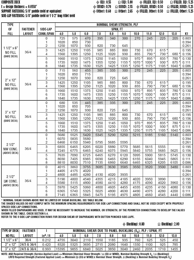
13 448 Table I and I-M list typical factors to reflect deck profile, fastener pattern, and warping. Table II and II-M list the Moment of Inertia for SDI generic profiles used in DDM03. Table III and III-M list deck panel yield, ultimate strength and modulus of elasticity. Table IV and IV-M list nominal shear strength and flexibility of typical fasteners used at support and side-lap. Table V and V-M list the nominal tensile strength of concentrically loaded arcspot welds. Table VI and VI-M list the nominal tensile strength of screws. Table VII and VII-M list the nominal tensile strength of Buildex power driven fasteners used in DDM03. Table VIII and VIII-M list the nominal tensile strength of Pneutek power driven fasteners used in DDM03. Table IX and IX-M list the nominal tensile strength of Hilti power driven fasteners used in DDM03. Table X and X-M list the fastener pattern factors β with different deck profile and fastener pattern for weld and mechanical fastener. Appendix V Load Tables The load tables are showing nominal values, which must not be used without applying the proper resistance or safety factors. For LRFD, the table value must be multiplied by a resistance factor when comparing to force evaluated using Load and Resistance Factor Design.
14 449 For ASD, the table value must be divided by a safety factor when comparing to the forces evaluated using Allowable Stress Design. Nominal diaphragm shears due to panel buckling are tabulated to check whether it governs over the connector strength for diaphragm design. Shaded values or no values do not comply with the minimum spacing for side-lap connections and shall not be used except with properly spaced sidelap connections. Shade values are the rows with 0 side-lap connection, and can be referred conservatively for diaphragm with button punched side-laps. For each design thickness and combination of support/side-lap fastening: 1.5 in. (38mm), 2 in. (51mm) and 3 in. (76mm) composite deck load table is shown with normal or lightweight structural concrete fill; 9/16in. (14mm) x 2 ½in. (64mm) form deck load table is shown with normal or lightweight structural concrete fill, and with insulating concrete assembled as Type I and Type II. A user-friendly table of contents for diaphragm load tables is added on page AV-4. A composite deck diaphragm load table is shown at the end of this paper as an example. Conclusion The changes made to DDM03 meet the designer s needs of conception using either ASD or LRFD code in either U.S. or SI units. The diaphragm shear values are tabulated in nominal values so to allow designers to apply safety or resistance factors according to the design code selected. Further research is required to justify these factors as listed in Supplement 2004 to the North American Specification for the Design of Cold-Formed Steel Structural Members, 2001 Edition. Example 7A takes into account the load eccentricity on the support welds in side lap flutes, and considered no reduction for edge screws in tension. Future editions of the North American Specification for the Design of Cold- Formed Steel Structural Members may modify this condition. SDI published white paper on Deeper Steel Deck and Cellular Diaphragm for the strength and stiffness calculation. Review of previous test
15 450 results showed that the SDI method has merit for use in evaluating strength and stiffness of cellular diaphragms with flat plate or mirror image closures, and of long span decks. American Iron and Steel Institute (AISI) and SDI jointly plan some more tests to be done for Deep Deck diaphragm action study. Appendix. - References 1. Luttrell, L. D., Deeper Steel Deck And Cellular Diaphragms (DSDCD), Steel Deck Institute, Luttrell, L. D., Diaphragm Design Manual Second Edition (DDM02), Steel Deck Institute, Luttrell, L. D., Diaphragm Design Manual Third Edition (DDM03), Steel Deck Institute, Luttrell, L. D., Steel Deck Institute Diaphragm Design Manual First Edition (DDM01), Minimum Design Loads in Buildings and Other Structures, ASCE 7-98, American Society of Civil Engineers. 6. North American Specification for the Design of Cold-Formed Steel Structural Members, American Iron and Steel Institute, CANACERO, Canadian Standards Association, Roof Deck Construction Handbook (RDCH), Steel Deck Institute, Supplement 2004 to the North American Specification for the Design of Cold-Formed Steel Structural Members, 2001 Edition, American Iron and Steel Institute, CANACERO, Canadian Standards Association.
16 451 Appendix. - Notation A g Tension rod cross-section area DL Dead loads e Perimeter edge fastener spacing F y Panel yield strength K Number of fasteners per panel width taking into account eccentric loading. LL Live loads L v Purlin or joist spacing P n Nominal diaphragm strength P u Required factored diaphragm strength for LRFD Q Fastener required allowable shear strength Q f Fastener strength, panel-to-frame Q u Fastener required factored shear strength S n Nominal linear diaphragm shear S u Required factored linear diaphragm shear for LRFD t Base sheet metal thickness T Fastener required allowable tensile strength T u Fastener required factored tensile strength β Fastener pattern factor Φ, Φ u Resistance factor Ω, Ω u Safety factor
17 452
The 2013 AISI Cold-Formed Steel Design Manual
 Missouri University of Science and Technology Scholars' Mine International Specialty Conference on Cold- Formed Steel Structures (2014) - 22nd International Specialty Conference on Cold-Formed Steel Structures
AISI Newly Developed Standard AISI S310-13, North American Standard for the Design of Profiled Steel Diaphragm Panels
 Missouri University of Science and Technology Scholars' Mine International Specialty Conference on Cold- Formed Steel Structures (2014) - 22nd International Specialty Conference on Cold-Formed Steel Structures
INTERNATIONAL ASSOCIATION OF PLUMBING AND MECHANICAL OFFICIALS, EVALUATION SERVICES EVALUATION CRITERIA FOR STEEL ROOF DECK.
 INTERNATIONAL ASSOCIATION OF PLUMBING AND MECHANICAL OFFICIALS, EVALUATION SERVICES EVALUATION CRITERIA FOR STEEL ROOF DECK EC 007-2010 e1 1.0 INTRODUCTION 1.1 Purpose: This criteria establishes the requirements
Steel Roof Deck EC X
 IAPMO ES Cover Sheet Evaluation Criteria of Steel Roof Deck EC 007-200 Posted for public commenting on 10/16/2009 to 11/12/2009 INTERNATIONAL ASSOCIATION OF PLUMBING AND MECHANICAL OFFICIALS, EVALUATION
The 2008 AISI Cold-formed Steel Design Manual
 Missouri University of Science and Technology Scholars' Mine International Specialty Conference on Cold- Formed Steel Structures (2010) - 20th International Specialty Conference on Cold-Formed Steel Structures
Top Arc Seam Weld Shear Strength and Stiffness for Sheet-to-sheet Connections
 Missouri University of Science and Technology Scholars' Mine International Specialty Conference on Cold- Formed Steel Structures (2012) - 21st International Specialty Conference on Cold-Formed Steel Structures
DIVISION: METALS SECTION: METAL FASTENINGS SECTION: STEEL DECKING REPORT HOLDER: HILTI, INC.
 0 Most Widely Accepted and Trusted ICC ES Evaluation Report ICC ES 000 (800) 43 6587 (56) 699 0543 www.icc es.org ESR 97 Reissued /7 This report is subject to renewal /8. DIVISION: 05 00 00 METALS SECTION:
Originally Issued: 03/10/2017 Revised: 03/30/2019 Valid Through: 03/31/ Design
 Originally Issued: 03/10/2017 Revised: 03/30/2019 Valid Through: 03/31/2019 EVALUATION SUBJECT: STEEL DECK PANELS REPORT HOLDER NUCOR CORPORATION - VULCRAFT/VERCO GROUP VULCRAFT GROUP 7205 Gault Avenue
INTERNATIONAL ASSOCIATION OF PLUMBING AND MECHANICAL OFFICIALS, UNIFORM EVALUATION SERVICES
 INTERNATIONAL ASSOCIATION OF PLUMBING AND MECHANICAL OFFICIALS, UNIFORM EVALUATION SERVICES EVALUATION CRITERIA FOR STEEL COMPOSITE, NON-COMPOSITE AND ROOF DECK CONSTRUCTION EC 007-2015 (Adopted April
INTERNATIONAL ASSOCIATION OF PLUMBING AND MECHANICAL OFFICIALS, UNIFORM EVALUATION SERVICES
 INTERNATIONAL ASSOCIATION OF PLUMBING AND MECHANICAL OFFICIALS, UNIFORM EVALUATION SERVICES EVALUATION CRITERIA FOR STEEL COMPOSITE, NON-COMPOSITE AND ROOF DECK CONSTRUCTION EC 007-2015 (Adopted April
Testing and Evaluation of CFS L-headers
 Missouri University of Science and Technology Scholars' Mine International Specialty Conference on Cold- Formed Steel Structures (2008) - 19th International Specialty Conference on Cold-Formed Steel Structures
A Design Guide for Bracing Cold-formed Steel Structures
 Missouri University of Science and Technology Scholars' Mine International Specialty Conference on Cold- Formed Steel Structures (2006) - 18th International Specialty Conference on Cold-Formed Steel Structures
Originally Issued: 03/10/2017 Revised: 08/24/2018 Valid Through: 03/31/ Design
 EVALUATION SUBJECT: STEEL DECK PANELS REPORT HOLDER NUCOR CORPORATION - VULCRAFT/VERCO GROUP VULCRAFT GROUP 7205 Gault Avenue North Fort Payne, Alabama 35967 (256) 845-2460 VERCO DECKING, INC. a NUCOR
AISI S E1 AISI STANDARD. Errata to North American Specification. for the Design of Cold-Formed. Steel Structural Members.
 AISI S100-12-E1 AISI STANDARD Errata to North American Specification for the Design of Cold-Formed Steel Structural Members 2012 Edition Amendment on August 16, 2013 Errata to North American Specification
LEGACY REPORT ER ICC Evaluation Service, Inc. Reissued January 1, Legacy report on the 1997 Uniform Building Code
 LEGACY REPORT Reissued January 1, 2004 ICC Evaluation Service, Inc. www.icc-es.org Business/Regional Office # 5360 Workman Mill Road, Whittier, California 90601 # (562) 699-0543 Regional Office # 900 Montclair
DIVISION: METALS SECTION: STEEL DECKING REPORT HOLDER: EPIC METALS CORPORATION 11 TALBOT AVENUE RANKIN, PENNSYLVANIA 15104
 0 Most Widely Accepted and Trusted ICC ES Evaluation Report ICC ES 000 (800) 423 6587 (562) 699 0543 www.icc es.org ESR 2047 Reissued 07/207 This report is subject to renewal 07/209. DIVISION: 05 00 00
DIVISION 5 METALS SECTION METAL DECKING
 DIVISION 5 METALS SECTION 05 30 00 PART 1 GENERAL 1.01 SUMMARY A. Section Includes: All labor and materials required to furnish and install metal decking and accessories including shear connectors, closures,
IBC 2015 and Cold-Formed Steel Design Standards and Design Aids. Roger LaBoube Wei-Wen Yu Center for Cold-Formed Steel Structures
 IBC 2015 and Cold-Formed Steel Design Standards and Design Aids Roger LaBoube Wei-Wen Yu Center for Cold-Formed Steel Structures AISI Specifications 1946 1 st edition 2012 13 th edition 1946 Specification
DIVISION: METALS SECTION: METAL FASTENINGS DIVISION: STEEL DECKING REPORT HOLDER: HILTI, INC. EVALUATION SUBJECT:
 0 ICC-ES Evaluation Report ICC-ES 000 (800) 43-6587 (56) 699-0543 www.icc-es.org Most Widely Accepted and Trusted ESR-97 Reissued /7 Revised / This report is subject to renewal /. DIVISION: 05 00 00 METALS
LEGACY REPORT REPORT HOLDER: ITW RAMSET EVALUATION SUBJECT:
 0 Most Widely Accepted and Trusted ICC ES Legacy Report ICC ES 000 (800) 4 6587 (56) 699 054 www.icc es.org ER 580 Reissued 07/08 This report is subject to renewal 07/0. DIVISION: 05 00 00 METALS SECTION:
Behavior of Continuous Span Purlin Systems
 Missouri University of Science and Technology Scholars' Mine International Specialty Conference on Cold- Formed Steel Structures (1988) - 9th International Specialty Conference on Cold-Formed Steel Structures
The Contractor is responsible for quality control, including workmanship and materials furnished by his subcontractors and suppliers.
 SECTION 05 31 23 - STEEL ROOF DECKING PART 1 - GENERAL 1.1 RELATED DOCUMENTS A. Drawings and general provisions of the contract, including General and Supplementary Conditions and Division 01 - Specification
Composite Steel Deck - Slabs
 American National standards institute / steel deck institute T - CD - 2011 Test Standard for Composite Steel Deck - Slabs copyright 2012 steel deck institute disclaimer The Steel Deck Institute has developed
The Contractor is responsible for quality control, including workmanship and materials furnished by his subcontractors and suppliers.
 SECTION 05 31 13 STEEL FLOOR DECKING PART 1 - GENERAL 1.1 RELATED DOCUMENTS Drawings and general provisions of the contract, including General and Supplementary Conditions and Division 01 - Specification
DECK DAMAGE AND PENETRATIONS
 DECK DAMAGE AND PENETRATIONS Prepared By Richard B. Heagler, P.E. SDI CONSULTANT Copyright 1987 (Rev. 2000) All rights reserved P.O. Box 25 Fox River Grove, IL 60021 Phone: (847) 458-4647 Fax: (847) 458-4648
Longwave Buckling of Cold-formed Steel Studs Using Direct Strength
 Missouri University of Science and Technology Scholars' Mine International Specialty Conference on Cold- Formed Steel Structures (2006) - 18th International Specialty Conference on Cold-Formed Steel Structures
INTERNATIONAL ASSOCIATION OF PLUMBING AND MECHANICAL OFFICIALS UNIFORM EVALUATION SERVICE EVALUATION CRITERIA FOR
 INTERNATIONAL ASSOCIATION OF PLUMBING AND MECHANICAL OFFICIALS UNIFORM EVALUATION SERVICE EVALUATION CRITERIA FOR SINGLE SKIN STEEL ROOF AND WALL PANELS EC 011-2015 (Adopted - September 2013, Revision
Angle Cleat Base Connections
 Missouri University of Science and Technology Scholars' Mine International Specialty Conference on Cold- Formed Steel Structures (2010) - 20th International Specialty Conference on Cold-Formed Steel Structures
Design of Steel Joists and Roof Decks
 Design of Steel Joists and Roof Decks Michael R. Miller, P. E. Topics for Discussion Design Responsibility What is a standard joist? Assumptions Dimensions Designations Joist Design for Wind Uplift Properly
ICC-ES Evaluation Report Reissued June 1, 2010 This report is subject to re-examination in one year.
 ICC-ES Evaluation Report ESR-409 Reissued June, 00 This report is subject to re-examination in one year. www.icc-es.org (800) 4-6587 (56) 699-054 A Subsidiary of the International Code Council DIVISION:
STEEL DECK INSTITUTE Industry Standard Terms & Definitions
 s Industry Standard Terms & Definitions November 2016 Industry Standard Terms & Definitions A specialized set of jargon to describe common terms used by manufacturers and other professionals associated
Direct Strength Design of Cold-formed C-sections in Combined Bending and Shear
 issouri University of Science and Technology Scholars' ine International Specialty Conference on Cold- Formed Steel Structures (2010) - 20th International Specialty Conference on Cold-Formed Steel Structures
Industry Standard Terms & Definitions Of The Steel Deck Institute
 Industry Standard Terms & Definitions Of The Steel Deck Institute A specialized set of jargon to describe common terms used by manufacturers and other professionals associated with the usage of Steel Deck
Strength of Arc Spot Welds Made in Single and Multiple Steel Sheets
 Missouri University of Science and Technology Scholars' Mine International Specialty Conference on Cold- Formed Steel Structures (2008) - 19th International Specialty Conference on Cold-Formed Steel Structures
Performance of Deep Leg L-headers
 Missouri University of Science and Technology Scholars' Mine International Specialty Conference on Cold- Formed Steel Structures (2004) - 17th International Specialty Conference on Cold-Formed Steel Structures
Contents. Tables. Notation xii Latin upper case letters Latin lower case letters Greek upper case letters Greek lower case letters. Foreword.
 Tables x Notation xii Latin upper case letters Latin lower case letters Greek upper case letters Greek lower case letters xii xiv xvi xvi Foreword xviii 1 Introduction 1 1.1 Aims of the Manual 1 1.2 Eurocode
Hilti, Inc South 122 nd East Avenue Tulsa, OK
 Attached are page(s) from the 2013 North American Product Technical Guide Volume 1 Direct Fastening. For complete details on this product, including data development, product specifications, general suitability,
Structural Detailing of Openings in Sandwich Panels
 Missouri University of Science and Technology Scholars' Mine International Specialty Conference on Cold- Formed Steel Structures (1996) - 13th International Specialty Conference on Cold-Formed Steel Structures
Structural vs Nonstructural Members. Roger LaBoube, Ph.D., P.E. Wei-Wen Yu Center for Cold-Formed Steel Structures
 Structural vs Nonstructural Members Roger LaBoube, Ph.D., P.E. Wei-Wen Yu Center for Cold-Formed Steel Structures Behavior of Cold-Formed Steel Members STEEL DESIGN SPECIFICATIONS Type of steel Specification
STEEL STRUCTURAL SYSTEMS
 STEEL STRUCTURAL SYSTEMS Steel elements are of two basic types: Structural steel shapes are formed into their final shapes by hot-rolling. This method produces such common elements as wide flange sections,
On Design of Profiled Sheets with Varying Cross Sections
 Missouri University of Science and Technology Scholars' Mine International Specialty Conference on Cold- Formed Steel Structures (1992) - 11th International Specialty Conference on Cold-Formed Steel Structures
Roof Diaphragm Strength and Stiffness
 Missouri University of Science and Technology Scholars' Mine nternational Specialty Conference on Cold- Formed Steel Structures (2004) - 17th nternational Specialty Conference on Cold-Formed Steel Structures
INTERNATIONAL ASSOCIATION OF PLUMBING AND MECHANICAL OFFICIALS UNIFORM EVALUATION SERVICES EVALUATION CRITERIA FOR
 INTERNATIONAL ASSOCIATION OF PLUMBING AND MECHANICAL OFFICIALS UNIFORM EVALUATION SERVICES EVALUATION CRITERIA FOR THE TESTING AND ANALYSIS OF STEEL SHEET SHEATHING FOR WOOD AND COLD FORMED STEEL LIGHT
Lateral System Analysis and Confirmation Design November 15, 2004
 Jonathan Hill Structural AE Faculty Consultant Dr. Hanagan Lynde and Harry Bradley School of Technology & Trade Milwaukee, Wisconsin Lateral System Analysis and Confirmation Design November 15, 2004 Executive
RCKW Kneewall Connectors
 This product is preferable to similar connectors because of a) easier installation, b) higher loads, c) lower installed cost, or a combination of these features. The Simpson Strong-Tie RCKW rigid connectors
Pull-Through Failure Tests of Thin Steel Roof Battens under Wind Uplift Loads
 Missouri University of Science and Technology Scholars' Mine International Specialty Conference on Cold- Formed Steel Structures (2014) - 22nd International Specialty Conference on Cold-Formed Steel Structures
Appendix I ESTIMATED DESIGN WIND PRESSURE AND STRENGTHS OF CONNECTIONS OF JOPLIN HOME DEPOT BUILDING
 ESTIMATED DESIGN WIND PRESSURE AND STRENGTHS OF CONNECTIONS OF JOPLIN HOME DEPOT BUILDING I.1 ESTIMATED DESIGN WIND PRESSURE BASED ON BOCA NBC/1996 Basic design wind speed: V = 90 mph (3 s gust) Exposure
Masonry and Cold-Formed Steel Requirements
 PC UFC Briefing September 21-22, 2004 Masonry and Cold-Formed Steel Requirements David Stevens, ARA Masonry Requirements Composite Construction Masonry is often used in composite construction, such as
Significant Changes to AWC s Special Design Provisions for Wind and Seismic
 Significant Changes to AWC s Special Design Provisions for Wind and Seismic Michelle Kam-Biron, PE, SE, SECB Director of Education American Wood Council Copyright Materials This presentation is protected
Feasibility Study for a Repetitive Member Factor for Cold-formed Steel Framing Systems
 Missouri University of Science and Technology Scholars' Mine International Specialty Conference on Cold- Formed Steel Structures (2010) - 20th International Specialty Conference on Cold-Formed Steel Structures
Vibration Characteristics and Acceptability of Cold-formed Steel Joists
 Missouri University of Science and Technology Scholars' Mine International Specialty Conference on Cold- Formed Steel Structures (2006) - 18th International Specialty Conference on Cold-Formed Steel Structures
Cold-formed Steel for Students a Website
 Missouri University of Science and Technology Scholars' Mine International Specialty Conference on Cold- Formed Steel Structures (2010) - 20th International Specialty Conference on Cold-Formed Steel Structures
STEEL DESIGNERS MANUAL
 STEEL DESIGNERS MANUAL SIXTH EDITION The Steel Construction Institute Edited by Buick Davison Department of Civil & Structural Engineering, The University of Sheffield Graham W. Owens Director, The Steel
SECTION STEEL DECKING
 SECTION 05 31 00 STEEL DECKING SPEC WRITER NOTE: 1. Delete text between // // not applicable to project. Edit remaining text to suit project. 2. Refer to Section 05 36 00, COMPOSITE METAL DECKING for floor
Cold-formed Steel Special Bolted Moment Frames Capacity Design Requirements
 Missouri University of Science and Technology Scholars' Mine International Specialty Conference on Cold- Formed Steel Structures (2008) - 19th International Specialty Conference on Cold-Formed Steel Structures
3.6.0 Major Characteristics of Joist Series
 Structural Steel, Joists, and Metal Decking 177 3.6.0 Major Characteristics of Joist Series (By permission of Nucor Research and Development, Norfolk, Nebraska.) 3.6.1 General Information on K Series Joists
The Contractor is responsible for quality control, including workmanship and materials furnished by his subcontractors and suppliers.
 SECTION 05 31 33 - STEEL FORM DECKING PART 1 - GENERAL 1.1 RELATED DOCUMENTS A. Drawings and general provisions of the contract, including General and Supplementary Conditions and Division 01 - Specification
The following excerpt are pages from the North American Product Technical Guide, Volume 1: Direct Fastening, Edition 15.
 The following excerpt are pages from the North American Product Technical Guide, Volume 1: Direct Fastening, Edition 15. Please refer to the publication in its entirety for complete details on this product
SECTION METAL DECKING. A. Extent of metal decking is indicated on Plans, including basic layout for the following type of deck required:
 PART 1 GENERAL 1.1 WORK INCLUDED A. Extent of metal decking is indicated on Plans, including basic layout for the following type of deck required: 1.2 RELATED WORK 1. Metal Roof Deck. A. Structural Steel:
Developments and Future Needs in Welding Coldformed
 Missouri University of Science and Technology Scholars' Mine International Specialty Conference on Cold- Formed Steel Structures (1988) - 9th International Specialty Conference on Cold-Formed Steel Structures
Overview of the Standard for Seismic Design of Cold-formed Steel Structural Systems - Special Bolted Moment Frames
 Missouri University of Science and Technology Scholars' Mine International Specialty Conference on Cold- Formed Steel Structures (2008) - 19th International Specialty Conference on Cold-Formed Steel Structures
Nothing Flat About Steel Joists and Steel Deck On a Pitched Roof
 Nothing Flat About Steel Joists and Steel Deck On a Pitched Roof APRIL 18, 2018 Copyright 2018 Steel Joist Institute. All Rights Reserved. Presented by: Ben Pitchford, P.E. Thomas Sputo, Ph.D, P.E., S.E.
mortarless masonry Design Manual Part 1 (IS 456:2000) Section 1 Page 1 IS 456:2000 PLAIN AND REINFORCED CONCRETE - CODE OF PRACTICE
 Section 1 Page 1 IS 456:2000 PLAIN AND REINFORCED CONCRETE - CODE OF PRACTICE") SECTION 1. mortarless masonry Design Manual Part 1 (IS 456:2000) Section 1 Page 1 1.1 Overview of IS 456:2000 IS 456:2000 PLAIN AND REINFORCED CONCRETE - CODE OF PRACTICE IS 456:2000 is the current Indian
SECTION 1. mortarless masonry Design Manual Part 1 (IS 456:2000) Section 1 Page 1 1.1 Overview of IS 456:2000 IS 456:2000 PLAIN AND REINFORCED CONCRETE - CODE OF PRACTICE IS 456:2000 is the current Indian
SPECIFICATIONS FOR THE CONSTRUCTION OF NEW PASSENGER EQUIPMENT CARS PREFACE
 SPECIFICATIONS FOR THE CONSTRUCTION OF NEW PASSENGER EQUIPMENT CARS Standard ADOPTED 1939; ADVANCED TO STANDARD, 1945. PREFACE The specifications have been prepared on the basis that they will be used
Revisiting the SDI and ECCS methods for in-plane shear flexibility of metal roof deck diaphragms using 3D non-linear finite element analysis
 Revisiting the SDI and ECCS methods for in-plane shear flexibility of metal roof deck diaphragms using 3D non-linear finite element analysis F. Bakhti & R. Tremblay Ecole Polytechnique de Montreal, Canada
CTLGroup Report No A
 Report for DMFCWBS, LLC CTLGroup Report No. 055016A Limiting Heights of Composite Wall Assemblies Composed of Cold-Formed Steel Studs Sheathed with 1/2-in. Generic Gypsum Board for Interior Non-Load Bearing
Brent Ellmann Structural Option 200 Minuteman Park, Andover, MA Structural Consultant: Dr. Hanagan
 Brief Building Overview: 200 Minuteman Park stands as a 200,000 square foot Class A office building in Andover, Massachusetts, worth roughly $15,000,000. Although the building has a large square footage,
INTERNATIONAL ASSOCIATION OF PLUMBING AND MECHANICAL OFFICIALS UNIFORM EVALUATION SERVICES
 1.0 INTRODUCTION INTERNATIONAL ASSOCIATION OF PLUMBING AND MECHANICAL OFFICIALS UNIFORM EVALUATION SERVICES EVALUATION CRITERIA FOR COMPOSITE STEEL SHEET AND NONCOMBUSTIBLE SHEATHING PANELS EC 012-2016
A REPORT ON THE EFFECTS OF WIND SPEED ON TIMBER CONSTRUCTION JOSHUA HUENEFELD. B.S., Kansas State University, 2012 A REPORT
 A REPORT ON THE EFFECTS OF WIND SPEED ON TIMBER CONSTRUCTION by JOSHUA HUENEFELD B.S., Kansas State University, 2012 A REPORT submitted in partial fulfillment of the requirements for the degree MASTER
Design Manual and Catalog of Steel Deck Products STEEL DECK INSTITUTE MEMBER
 Design Manual and Catalog of Steel Deck Products s STEEL DECK INSTITUTE MEMBER Manufacturers of products History CMC Joist & Deck is a leading producer of steel deck, open-web steel joists, long span steel
Lightweight Steel Framing. DeltaStud Load Tables
 Lightweight Steel Framing DeltaStud Load Tables January 2013 Roger A. LaBoube, Ph.D, P.E. The load tables and technical information contained in this catalogue were prepared by Dr. Roger A. LaBoube, Ph.D,
TECHNICAL NOTE. Design of Diagonal Strap Bracing Lateral Force Resisting Systems for the 2006 IBC. On Cold-Formed Steel Construction INTRODUCTION
 TECHNICAL NOTE On Cold-Formed Steel Construction 1201 15th Street, NW, Suite 320 W ashington, DC 20005 (202) 785-2022 $5.00 Design of Diagonal Strap Bracing Lateral Force Resisting Systems for the 2006
Product Designation As specified in the AISI standard for cold formed steel framing General provisions A5.2.
 Steel Structural Systems (TRI-S) was founded in 2004 to meet the service needs of a growing industry. The company is a world-class manufacturer of light gauge steel framing components for the commercial
IAPMO ES. Cover Sheet. Evaluation Criteria of. COLD-FORMED STEEL or WOOD FRAMED / STEEL-SHEATHED SHEAR WALLS
 IAPMO ES Cover Sheet Evaluation Criteria of COLD-FORMED STEEL or WOOD FRAMED / STEEL-SHEATHED SHEAR WALLS Posted for public commenting on 12/11/08 thru 1/14/09 Comments currently under review International
Testing of Bolted Cold- Formed Steel Connections in Bearing (With and Without Washers) RESEARCH REPORT RP01-4
 RESEARCH REPORT RP01-4") research report Testing of Bolted Cold- Formed Steel Connections in Bearing (With and Without Washers) RESEARCH REPORT RP01-4 MARCH 2001 Committee on Specifications for the Design of Cold-Formed Steel
research report Testing of Bolted Cold- Formed Steel Connections in Bearing (With and Without Washers) RESEARCH REPORT RP01-4 MARCH 2001 Committee on Specifications for the Design of Cold-Formed Steel
The following excerpt are pages from the North American Product Technical Guide, Volume 1: Direct Fastening, Edition 15.
 The following excerpt are pages from the North American Product Technical Guide, Volume 1: Direct Fastening, Edition 15. Please refer to the publication in its entirety for complete details on this product
Web Crippling of Cold-formed Steel Members
 Missouri University of Science and Technology Scholars' Mine International Specialty Conference on Cold- Formed Steel Structures (2002) - 16th International Specialty Conference on Cold-Formed Steel Structures
Lateral load basics Code acceptance of Standard. Standard Overview 2008 Wind & Seismic Standard. Wind. Wind Load Path. IBC Section 1604.
 Outline 2005/2008 Special Design Provisions for Wind & Seismic Standard Lateral load basics Code acceptance of Standard 2005/2008 Wind & Seismic Standard Overview 2008 Wind & Seismic Standard John Buddy
Structural Engineering, Mechanics, and Materials. Preliminary Exam - Structural Design
 Fall Semester 2018 Preliminary Exam - Structural Design A small building is located in downtown Berkeley. The structural system, either structural steel or reinforced concrete, comprises gravity framing
FROM: SUBJECT: HILTI X-ENP-19, X-HSN 24 or X-U POWDER-ACTUATED FASTENER SUBSTITUTION REQUEST
 DATE: PROJECT: TO: FROM: SUBJECT: HILTI X-ENP-19, X-HSN 24 or X-U POWDER-ACTUATED FASTENER SUBSTITUTION REQUEST SPECIFICATION TITLE: SECTION: PAGE: ARTICLE/PARAGRAPH: DESCRIPTION: DESIGN DETAIL NO.: PROPOSED
THE SITUATION WITH STEEL DECKS
 THE SITUATION WITH STEEL DECKS Steel roof deck design can affect roof system selection and design by Mark S. Graham 32 www.professionalroofing.net MARCH 2017 teel roof decks commonly are encountered in
VOLUNTARY - EARTHQUAKE HAZARD REDUCTION IN EXISTING HILLSIDE BUILDINGS (Division 94 Added by Ord. No. 171,258, Eff. 8/30/96.)
") DIVISION 94 VOLUNTARY - EARTHQUAKE HAZARD REDUCTION IN EXISTING HILLSIDE BUILDINGS (Division 94 Added by Ord. No. 171,258, Eff. 8/30/96.) SEC. 91.9401. PURPOSE. (Amended by Ord. No. 172,592, Eff. 6/28/99,
DIVISION 94 VOLUNTARY - EARTHQUAKE HAZARD REDUCTION IN EXISTING HILLSIDE BUILDINGS (Division 94 Added by Ord. No. 171,258, Eff. 8/30/96.) SEC. 91.9401. PURPOSE. (Amended by Ord. No. 172,592, Eff. 6/28/99,
Check the strength of each type of member in the one story steel frame building below.
 CE 331, Summer 2015 nalysis of Steel Braced Frame Bldg 1 / 9 Check the strength of each type of member in the one story steel frame building below. 4 @ 8 ft B 20 f 1 2 3 @ 25 ft Side Elevation 3 4 Plan
Sabah Shawkat Cabinet of Structural Engineering 2017
 3.1-1 Continuous beams Every building, whether it is large or small, must have a structural system capable of carrying all kinds of loads - vertical, horizontal, temperature, etc. In principle, the entire
Hilton Baltimore Convention Center Hotel Western Podium
 Hilton Baltimore Convention Center Hotel Western Podium CHRIS SIMMONS Structural Option Faculty Consultant: Dr. Ali M. Memari Technical Report 1 TABLE OF CONTENTS EXECUTIVE SUMMARY. Page 3 INTRODUCTION..
PASSAIC COUNTY TECHNICAL INSTITUTE CCA 1422 NEW S.T.E.M. BUILDING 2017
 SECTION 053100 STEEL DECKING PART 1 - GENERAL 1.1 RELATED DOCUMENTS A. Drawings and general provisions of the Contract, including General and Supplementary Conditions and Division 01 Specification Sections,
BS EN :2004 EN :2004 (E)
") Contents List 1. General 1.1 Scope 1.1.1 Scope of Eurocode 2 1.1.2 Scope of Part 1-1 of Eurocode 2 1.2 Normative references 1.2.1 General reference standards 1.2.2 Other reference standards 1.3 Assumptions
Contents List 1. General 1.1 Scope 1.1.1 Scope of Eurocode 2 1.1.2 Scope of Part 1-1 of Eurocode 2 1.2 Normative references 1.2.1 General reference standards 1.2.2 Other reference standards 1.3 Assumptions
Cold-formed Steel Bolted Connections Without Washers on Oversized Holes Shear and Bearing Failures in Sheets
 Missouri University of Science and Technology Scholars' Mine International Specialty Conference on Cold- Formed Steel Structures (2008) - 19th International Specialty Conference on Cold-Formed Steel Structures
research report Flexural Behavior and Strength of Cold-Formed Steel L-Headers RESEARCH REPORT RP08-3 American Iron and Steel Institute
 research report Flexural Behavior and Strength of Cold-Formed Steel L-Headers RESEARCH REPORT RP08-3 2008 American Iron and Steel Institute Flexural Behavior and Strength of Cold-Formed Steel L-Headers
TCC/SHORE TRANSIT BUS MAINTENANCE FACILITY - PHASE II
 SECTION 052100 - STEEL JOISTS PART 1 - GENERAL 1.1 RELATED DOCUMENTS: A. Drawings and General Provisions of the Contract, including General and Supplementary Conditions and Division 1 Specification Sections
VERTICAL AND HORIZONTAL LATERAL LOAD SYSTEMS
 TECHNICAL NOTE On Cold-Formed Steel Construction $5.00 Light Gauge Steel Engineers Association Washington, D.C. Toll-Free: 1 (866) 465-4732 www.lgsea.com DESIGN VALUES FOR VERTICAL AND HORIZONTAL LATERAL
VARIOUS TYPES OF SLABS
 VARIOUS TYPES OF SLABS 1 CHOICE OF TYPE OF SLAB FLOOR The choice of type of slab for a particular floor depends on many factors. Economy of construction is obviously an important consideration, but this
Testing of steel l-headers on wood walls
 Missouri University of Science and Technology Scholars' Mine Center for Cold-Formed Steel Structures Library Wei-Wen Yu Center for Cold-Formed Steel Structures 5-1-2002 Testing of steel l-headers on wood
research report Cold-Formed Steel Gable End Wall Design Using the Prescriptive Method for One and Two Family Dwellings RESEARCH REPORT RP05-2
 research report Cold-Formed Steel Gable End Wall Design Using the Prescriptive Method for One and Two Family Dwellings RESEARCH REPORT RP05-005 REVISION 006 American Iron and Steel Institute Cold-Formed
CTLGroup Report No
 Report for DMFCWBS, LLC CTLGroup Report No. 055022 Limiting Heights of Composite Wall Assemblies Composed of Cold-Formed Steel Studs Sheathed with 5/8-in. USG Sheetrock Brand Firecode Type X Gypsum Panels
Lateral Strength of Wind Load Bearing Wall Studto-track
 Missouri University of Science and Technology Scholars' Mine International Specialty Conference on Cold- Formed Steel Structures (2000) - 15th International Specialty Conference on Cold-Formed Steel Structures
CONNECTOR S T U D S H E A R. Design for Composite Structural Action STUD SHEAR CONNECTOR APPLICATION
 S T U D S H E A R CONNECTOR STUD SHEAR CONNECTOR APPLICATION Design for Composite Structural Action Exterior ashlar-type masonry veneer, typically of clay brick or concrete block masonry, are commonly
Dynamic Time-history Analysis on Wind-induced Response of Light-weight Roof System
 Missouri University of Science and Technology Scholars' Mine International Specialty Conference on Cold- Formed Steel Structures (2012) - 21st International Specialty Conference on Cold-Formed Steel Structures
xiii Preface to the Fifth Edition Preface to the Second Edition Factors for Conversion to SI Units of
 Structural Steel Designer's Handbook Table Of Contents: Contributors xiii Preface to the Fifth Edition xv Preface to the Second Edition xvii Factors for Conversion to SI Units of xix Measurement Chapter