PROJECT MANUAL Volume 1. Project: Clayton Greenway System -Mark s Creek Bridge Replacement
|
|
|
- Felicia Gaines
- 6 years ago
- Views:
Transcription
1 PROJECT MANUAL Volume 1 Project: Clayton Greenway System -Mark s Creek Bridge Replacement Owner: Town of Clayton Construction Manager: Lysaght & Associates Issued August 9, 2017 COVER SHEET
2 TABLE OF CONTENTS PROJECT TITLE PAGE SEALS PAGE LIST OF DRAWING SHEETS ADVERTISEMENT FOR BIDS INSTRUCTIONS TO BIDDERS GEOTECHNICAL DATA BID FORM STIPULATED SUM (SINGLE-PRIME CONTRACT) BID FORM UNIT PRICES NOTICE OF AWARD SUMMARY CONTRACT MODIFICATION PROCEDURES SUBMITTAL PROCEDURES CLOSEOUT PROCEDURES PROJECT RECORD DOCUMENTS STRUCTURE DEMOLITION CAST-IN-PLACE CONCRETE STRUCTURAL STEEL FRAMING EXTERIOR ROUGH CARPENTRY CLEARING AND GRUBBING EROSION CONTROL EARTH MOVING STORM UTILITY DRAINAGE PIPING APPENDIX A GEOTECHMICAL REPORT APPENDIX B TOWN OF CLAYTON NOISE ORDINANCE END OF SECTION TABLE OF CONTENTS
3 Clayton Greenway System Mark s Creek Bridge Replacement 08/17 DOCUMENT PROJECT TITLE PAGE 1.1 PROJECT MANUAL VOLUME 1 A. Project: Clayton Greenway System Mark s Creek Bridge Replacement. B. Owner: Town of Clayton. C. Location: Clayton, NC D. Engineer Project No. LA E. Construction Manager Lysaght & Associates 120 St.Mary s St., Raleigh NC, (919) markb@lysaghtassocaites.com F. Document Issued: August END OF DOCUMENT PROJECT TITLE PAGE


4 Clayton Greenway System Mark s Creek Bridge Replacement 08/17 DOCUMENT SEALS PAGE 1.1 DESIGN PROFESSIONALS OF RECORD A. Civil Engineer: 1. Carl Simmons CMS Engineering PO Box 780 Kinightdale, NC License Number: NC Responsible for Sections: , B. Structural Engineer: 1. Charles Lysaght: Lysagth & Associates 120 St.Mary s St., Raleigh, NC License Number: NC Responsible for Sections: , , , ,. END OF DOCUMENT SEALS PAGE
5 Clayton Greenway System Mark s Creek Bridge Replacement 08/17 DOCUMENT LIST OF DRAWING SHEETS 1.1 LIST OF DRAWINGS A. List of Drawings: Drawings consist of the following Contract Drawings and other drawings of type indicated: 1. C1 BRIDGE EROSION CONTROL PLAN & DETAILS by CMS Engineering 2. C2 BRIDGE PLAN & PROFILE by CMS Engineering 3. S100 GENERAL STUCTURAL NOTES by Lysaght & Associates 4. S101 BRIDGE PLAN by Lysaght & Associates 5. S201 STRUCTURAL DETAILS by Lysaght & Associates. END OF DOCUMENT LIST OF DRAWING SHEETS
6 Clayton Greenway System Mark s Creek Bridge Replacement 08/17 DOCUMENT ADVERTISEMENT FOR BIDS 1.1 PROJECT INFORMATION A. Notice to Bidders: Qualified bidders may submit bids for project as described in this Document. Submit bids according to the Instructions to Bidders. B. Project Identification: Clayton Greenway System Mark s Creek Bridge Replacement Project Number LA Project Location: Mark s Creek Bridge on Clayton Greenway System - Clayton, NC. Access to bridge is located via greenway access at the end of the cul-de-sac on Charleston Dr in the Riverwood Subdivision in Clayton, NC C. Owner: Town of Clayton, NC 1. Owner's Representative: Andy Simerman Construction Project Administrator 111 E. Second St., Clayton, NC asimerman@townofclaytonnc.org, telephone: (919) D. Construction Manager: Mark Blankinship - Lysaght & Associates 120 St. Mary s St., E- Mail: markb@lysaghtassociates.com, (919) E. Project Description: Project consists of: Replacement of damaged Mark s Creek Bridge including removal and disposal of existing damaged bridge and installation of new single span weathered steel bridge with associated footings/abutments, grading, and greenway repair. The scope includes protection and/or repair of any structures, surfaces, site facilities accessed during the project. 1. Project cost range is anticipated to be under $200,000. F. Construction Contract: Bids will be received for the following Work: 1. General Contract (all trades). The Bid shall be a lump sum bid including the entire scope of work. 1.2 BID SUBMITTAL AND OPENING A. The Town of Clayton will receive bids for the project in a sealed envelope addressed to the Town of Clayton - Clayton Town Hall 111 E. Second St., Clayton, NC Sealed bids shall be addressed to Andy Simerman, Construction Project Administrator. Bids will be received until the bid time and date at the location given below. Owner will consider bids prepared in compliance with the Instructions to Bidders. 1. Bid Date: Bids accepted until September 21, Bid Time: Until 3:00 p.m. local time. 3. Location: Clayton Town Hall 111 E. Second St., Clayton, NC ADVERTISEMENT FOR BIDS
7 Clayton Greenway System Mark s Creek Bridge Replacement 08/17 B. Bids shall be clearly marked on the outside Clayton Greenway System Mark s Creek Bridge Replacement. 1.3 BID SECURITY A. Bid security shall be submitted with each bid in the amount of 5% of the Bid Price. In lieu of Bid Security, a Bid Bond will be accepted. No bids may be withdrawn for a period of 60 days after opening of bids. Owner reserves the right to reject any and all bids and to waive informalities and irregularities. 1.4 PREBID MEETING A. Prebid Meeting: A Prebid meeting for all bidders will be held at the Site on the Clayton Greenway System at Mark s Creek located at the end of Charleston Dr. in the Riverwood Subdivision in Clayton NC on September 6, 2017 at 10:00 a.m. local time. Prospective prime bidders are requested to attend. 1. Bidders' Questions: The Construction Manager will provide responses at Prebid conference to bidders' questions received up to two business days prior to conference. 1.5 DOCUMENTS A. Procurement and Contracting Documents: Obtain after August 18, 2017 by contacting Owner or Construction Manager. Documents will be provided to prime bidders only; only complete sets of documents will be issued. Documents may be transmitted electronically, or hard copies may be may be picked up at the Town of Clayton Town Hall at the address listed above. 1. Deposit for hard copies: $75.00 made payable to Town of Clayton. 1.6 TIME OF COMPLETION AND PENALTY A. Successful bidder shall begin the Work upon receipt of the Notice to Proceed and shall complete the Work within the Contract Time which is One-hundred (100) consecutive calendar days. Work is subject to a penalty of $200 per calendar day beyond the time of completion. 1.7 BIDDER'S QUALIFICATIONS A. Bidders must be properly licensed under the laws governing their respective trades and be able to obtain insurance and bonds required for the Work. A Performance Bond, separate Labor and Material Payment Bond, and Insurance in a form acceptable to Owner will be required of the successful Bidder. By submitting a bid proposal on this project, the contractor submits that he is qualified to perform the work satisfactorily and that he has completed similar work in the past. The owner reserved the right to request Qualifications before or after the bid date. ADVERTISEMENT FOR BIDS
8 Clayton Greenway System Mark s Creek Bridge Replacement 08/ NOTIFICATION A. This Advertisement for Bids document is issued by Mark Blankinship Construction Manager, Lysaght & Associates END OF DOCUMENT ADVERTISEMENT FOR BIDS
9 Clayton Greenway System Mark s Creek Bridge Replacement 08/17 DOCUMENT INSTRUCTIONS TO BIDDERS 1.1 INSTRUCTIONS TO BIDDERS 1.2 ARTICLE 1 - DEFINITIONS A. Instructions to Bidders is constituted by this Document and other information found in the Project Manual and drawings for this project. 1.3 ARTICLE 2 - BIDDER'S REPRESENTATIONS A. Section : The Bidder has investigated all required fees, permits, and regulatory requirements of authorities having jurisdiction and has properly included in the submitted bid the cost of such fees, permits, and requirements not otherwise indicated as provided by Owner. The Contractor is responsible for acquiring any permit required by the NC State Building Code. The Town of Clayton will not be collecting a permit fee on this project B. Section 2.1.5: The Bidder is a properly licensed Contractor according to the laws and regulations of North Carolina and meets qualifications indicated in the Procurement and Contracting Documents. C. Section 2.1.6: The Bidder has incorporated into the Bid adequate sums for work performed by installers whose qualifications meet those indicated in the Procurement and Contracting Documents. 1.4 ARTICLE 3 - BIDDING DOCUMENTS A Interpretation or Correction of Procurement and Contracting Documents: 1. Section : a Submit Bidder's Requests for Interpretation to the Construction Manager Mark Blankinship Lysaght & Associates via to markb@lysaghtassociates.com 2. Section 3.4.3: a Addenda may be issued at any time prior to the receipt of bids. 3. Section : SUPPLEMENTARY INSTRUCTIONS TO BIDDERS
10 Clayton Greenway System Mark s Creek Bridge Replacement 08/17 a Owner may elect to waive the requirement for acknowledging receipt of Addenda as follows: 1) Information received as part of the Bid indicates that the Bid, as submitted, reflects modifications to the Procurement and Contracting Documents included in an unacknowledged Addendum. 2) Modifications to the Procurement and Contracting Documents in an unacknowledged Addendum do not, in the opinion of Owner, affect the Contract Sum or Contract Time. 1.5 ARTICLE 4 - BIDDING PROCEDURES A Preparation of Bids: 1. Section : a Printable electronic Bid Forms and related documents are available from Construction Manager and are included in the Project Manual. 2. Section 4.1.8: a The Bid shall include unit prices when called for by the Procurement and Contracting Documents. Owner may elect to consider unit prices in the determination of award. Unit prices will be incorporated into the Contract. 3. Section 4.1.9: a Owner may elect to disqualify a bid due to failure to submit a bid in the form requested, failure to bid requested alternates or unit prices, failure to complete entries in all blanks in the Bid Form, or inclusion by the Bidder of any alternates, conditions, limitations or provisions not called for. 4. Section : a Bids shall include sales and use taxes. Contractors shall show separately with each monthly payment application the sales and use taxes paid by them and their subcontractors in the form indicated. Reimbursement of sales and use taxes, if any, shall be applied for by Owner for the sole benefit of Owner. B Submission of Bids: 1. Section : a Include Bidder's Contractor License Number applicable in Project jurisdiction on the face of the sealed bid envelope. C Modification or Withdrawal of Bids: 1. Section 4.4.2: SUPPLEMENTARY INSTRUCTIONS TO BIDDERS
11 Clayton Greenway System Mark s Creek Bridge Replacement 08/17 a Such modifications to or withdrawal of a bid may only be made by persons authorized to act on behalf of the Bidder. Authorized persons are those so identified in the Bidder's corporate bylaws, specifically empowered by the Bidder's charter or similar legally binding document acceptable to Owner, or by a power of attorney, signed and dated, describing the scope and limitations of the power of attorney. Make such documentation available to Owner at the time of seeking modifications or withdrawal of the Bid. b Owner will consider modifications to a bid written on the sealed bid envelope by authorized persons when such modifications comply with the following: the modification is indicated by a percent or stated amount to be added to or deducted from the Bid; the amount of the Bid itself is not made known by the modification; a signature of the authorized person, along with the time and date of the modification, accompanies the modification. Completion of an unsealed bid form, awaiting final figures from the Bidder, does not require power of attorney due to the evidenced authorization of the Bidder implied by the circumstance of the completion and delivery of the Bid. 1.6 ARTICLE 5 - CONSIDERATION OF BIDS A Rejection of Bids: 1. Section 5.2.1: a Owner reserves the right to reject a bid based on Owner's and Construction Managers evaluation of qualification information submitted following opening of bids. Owner's evaluation of the Bidder's qualifications will include: status of licensure and record of compliance with licensing requirements, record of quality of completed work, record of Project completion and ability to complete, record of financial management including financial resources available to complete Project and record of timely payment of obligations, record of Project site management including compliance with requirements of authorities having jurisdiction, record of and number of current claims and disputes and the status of their resolution, and qualifications of the Bidder's proposed Project staff and proposed subcontractors. 1.7 ARTICLE 6 - POSTBID INFORMATION A Contractor's Qualification Statement: 1. Add Section 6.1.1: a Submit Contractor's Qualification Statement no later than two business days following Architect's request. 1.8 ARTICLE 7 - PERFORMANCE BOND AND PAYMENT BOND A Bond Requirements: 1. Section : SUPPLEMENTARY INSTRUCTIONS TO BIDDERS
12 Clayton Greenway System Mark s Creek Bridge Replacement 08/17 a Both a Performance Bond and a Payment Bond will be required, each in an amount equal to 100 percent of the Contract Sum. B Time of Delivery and Form of Bonds: a. The Bidder shall deliver the required bonds to Owner no later than 10 days after the date of Notice of Intent to Award and no later than the date of execution of the Contract, whichever occurs first. Owner may deem the failure of the Bidder to deliver required bonds within the period of time allowed a default. b Bonds shall be executed and be in force on the date of the execution of the Contract. 1.9 ARTICLE 8 - FORM OF AGREEMENT BETWEEN OWNER AND CONTRACTOR A. The Form of Agreement between Owner and Contractor shall be as prepared by the Construction Manager and approved by the Owner ARTICLE 9 - EXECUTION OF THE CONTRACT A. Article 9: Subsequent to the Notice of Intent to Award, and within 10 days after the prescribed Form of Agreement is presented to the Awardee for signature, the Awardee shall execute and deliver the Agreement to Owner through Construction Manager, in such number of counterparts as Owner may require Owner may deem as a default the failure of the Awardee to execute the Contract and to supply the required bonds when the Agreement is presented for signature within the period of time allowed Unless otherwise indicated in the Procurement and Contracting Documents or the executed Agreement, the date of commencement of the Work shall be the date of the executed Agreement or the date of Notice to Proceed, whichever is sooner In the event of a default, Owner may declare the amount of the Bid security forfeited and elect to either award the Contract to the next responsible bidder or readvertise for bids. END OF DOCUMENT SUPPLEMENTARY INSTRUCTIONS TO BIDDERS
13 Clayton Greenway System Mark s Creek Bridge Replacement 08/17 DOCUMENT GEOTECHNICAL DATA 1.1 GEOTECHNICAL DATA A. This Document with its referenced attachments is part of the Procurement and Contracting Requirements for Project. They provide Owner's information for Bidders' convenience and are intended to supplement rather than serve in lieu of Bidders' own investigations. They are made available for Bidders' convenience and information, but are not a warranty of existing conditions. This Document and its attachments are not part of the Contract Documents. B. A geotechnical investigation report for Greenway Pedestrian Bearing Conditions prepared by GeoTechnologies, Inc., dated April 12, 2017 is available for viewing as appended to this Document. C. Related Requirements: 1. Document "Instructions to Bidders" for the Bidder's responsibilities for examination of Project site and existing conditions. END OF DOCUMENT GEOTECHNICAL DATA
14 Clayton Greenway System Mark s Creek Bridge Replacement 08/17 DOCUMENT BID FORM STIPULATED SUM (SINGLE-PRIME CONTRACT) 1.1 BID INFORMATION A. Bidder:. B. Project Name: Clayton Greenway System Mark s Creek Bridge Replacement. C. Project: Location: Clayton, NC. D. Owner: Town of Clayton. E. Owner Project Number: LA F. Construction Manager: Lysaght & Associates 120 St.Mary s St., Raleigh NC, (919) markb@lysaghtassocaites.com 1.2 CERTIFICATIONS AND BASE BID A. Base Bid, Single-Prime (All-Trades) Contract: The undersigned Bidder, having carefully examined the Procurement and Contracting Requirements, Conditions of the Contract, Drawings, Specifications, and all subsequent Addenda, as prepared by Lysaght & Associates and CMS Engineering, having visited the site, and being familiar with all conditions and requirements of the Work, hereby agrees to furnish all material, labor, equipment and services, including all scheduled allowances, necessary to complete the construction of above-named Project, according to the requirements of the Procurement and Contracting Documents, for the stipulated sum of: 1. Dollars ($ ). 2. The above amount may be modified by amounts indicated by the Bidder on the attached Bid Supplement - Unit Prices. 1.3 BID GUARANTEE A. The undersigned Bidder agrees to execute a contract for this Work in the above amount and to furnish surety as specified within 10 days after a written Notice of Award, if offered within 60 days after receipt of bids, and on failure to do so agrees to forfeit to Owner the attached cash, cashier's check, certified check, U.S. money order, or bid bond, as liquidated damages for such failure, in the following amount constituting five percent (5%) of the Base Bid amount above: 1. Dollars ($ ). B. In the event Owner does not offer a Notice of Award within the time limits stated above, Owner will return to the undersigned the cash, cashier's check, certified check, U.S. money order, or bid bond. BID FORM - CONSTRUCTION MANAGEMENT (SINGLE-PRIME CONTRACT)
15 Clayton Greenway System Mark s Creek Bridge Replacement 08/ TIME OF COMPLETION A. The undersigned Bidder proposes and agrees hereby to commence the Work of the Contract Documents on a date specified in a written Notice to Proceed to be issued by Construction Manager, and shall fully complete the Work within 100 calendar days. 1.5 ACKNOWLEDGEMENT OF ADDENDA A. The undersigned Bidder acknowledges receipt of and use of the following Addenda in the preparation of this Bid: ( If not applicable, mark N/A) 1. Addendum No. 1, dated. 2. Addendum No. 2, dated. 1.6 BID SUPPLEMENTS A. The following supplements are a part of this Bid Form and are attached hereto: 1. Bid Form Supplement - Unit Prices. 1.7 CONTRACTOR'S LICENSE A. The undersigned further states that it is a duly licensed contractor, for the type of work proposed, in Clayton, NC, and that all fees, permits, etc., pursuant to submitting this proposal have been paid in full. 1.8 SUBMISSION OF BID A. Respectfully submitted this day of, B. Submitted By: (Name of bidding firm or corporation). C. Authorized Signature: (Handwritten signature). D. Signed By: (Type or print name). E. Title: (Owner/Partner/President/Vice President). F. Witnessed By: (Handwritten signature). G. Attest: (Handwritten signature). H. By: (Type or print name). I. Title: (Corporate Secretary or Assistant Secretary). J. Street Address:. BID FORM - CONSTRUCTION MANAGEMENT (SINGLE-PRIME CONTRACT)
16 Clayton Greenway System Mark s Creek Bridge Replacement 08/17 K. City, State, Zip:. L. Phone:. M. License No.:. N. Federal ID No.: (Affix Corporate Seal Here). END OF DOCUMENT BID FORM - CONSTRUCTION MANAGEMENT (SINGLE-PRIME CONTRACT)
17 Clayton Greenway System Mark s Creek Bridge Replacement 08/17 DOCUMENT UNIT PRICES FORM 1.1 BID INFORMATION A. Bidder:. B. Prime Contract: Stipulated Sum (Single Prime Contract). C. Project Name: Clayton Greenway System Mark s Creek Bridge Replacement. D. Project Location: Clayton, NC. E. Owner: Town of Clayton. F. Owner Project Number: LA G. Construction Manager: Lysaght & Associates 120 St.Mary s St., Raleigh NC, (919) markb@lysaghtassocaites.com 1.2 BID FORM SUPPLEMENT A. This form is required to be attached to the Bid Form. B. The undersigned Bidder proposes the amounts below be added to or deducted from the Contract Sum on performance and measurement of the individual items of Work as directed by the Owner or Constriction Manager. C. If the unit price does not affect the Work of this Contract, the Bidder shall indicate "NOT APPLICABLE." 1.3 UNIT PRICES A. Unit-Price No. 1: Removal of unsatisfactory soil below foundations and replacement with washed stone. 1. Dollars ($ ) per Cubic yard. B. Unit-Price No. 2: Removal of unsatisfactory soil below foundations and replacement with lean concrete. 1. Dollars ($ ) per Cubic yard. C. Unit Price No. 3: Installation of 6 high temporary chain link fence. 1. Dollars ($ ) per linear foot D. Unit Price no. 4: Installation of tree protection fence. UNIT PRICES FORM
18 Clayton Greenway System Mark s Creek Bridge Replacement 08/17 1. Dollars ($ ) per linear foot E. Unit Price No. 5: Installation of greenway paving according to the Town of Clayton typical bikeway/greenway pavement section shown on sheet C1. 1. Dollars ($ ) per Square yard 1.4 SUBMISSION OF BID SUPPLEMENT A. Respectfully submitted this day of, B. Submitted By: (Insert name of bidding firm or corporation). C. Authorized Signature: (Handwritten signature). D. Signed By: (Type or print name). E. Title: (Owner/Partner/President/Vice President). END OF DOCUMENT UNIT PRICES FORM
19 Clayton Greenway System Mark s Creek Bridge Replacement 086/17 DOCUMENT NOTICE OF AWARD 1.1 BID INFORMATION A. Bidder:. B. Bidder's Address:. C. Prime Contract: Stipulated Sum (Single-Prime Contract). D. Project Name: Clayton Greenway System Mark s Creek Bridge Replacement. E. Project Location: Clayton, NC. F. Owner: Town of Clayton. G. Owner Project Number: LA NOTICE OF INTENT TO AWARD CONTRACT A. Notice: The above Bidder is hereby notified that their bid, dated, for the above Contract has been considered and the Bidder is hereby awarded a contract for The Replacement of the Mark s Creek Bridge at the Clayton Greenway System according to the Bid Documents. B. Contract Sum: The Contract Sum is dollars ($ ). 1.3 EXECUTION OF CONTRACT A. Contract Documents: Copies of the Contract Documents will be made available to the Bidder immediately. The Bidder must comply with the following conditions precedent within 10 days of the above date of issuance of the Notice: 1. Deliver to Owner 3 sets of fully executed copies of the Contract Documents. 2. Deliver with the executed Contract Documents Bonds and Certificates of Insurance required by the Contract Documents. B. Compliance: Failure to comply with conditions of this Notice within the time specified will entitle Owner to consider the Bidder in default, annul this Notice, and declare the Bidder's Bid security forfeited. 1. Within 10 days after the Bidder complies with the conditions of this Notice, Owner will return to the Bidder one fully executed copy of the Contract Documents. 1.4 NOTIFICATION A. This Notice is issued by: NOTICE OF AWARD
20 Clayton Greenway System Mark s Creek Bridge Replacement 086/17 1. Owner:. 2. Authorized Signature: (Handwritten signature). 3. Signed By: (Type or print name). 4. Title: (Owner/Partner/President/Vice President). END OF DOCUMENT NOTICE OF AWARD
21 Clayton Greenway System Mark s Creek Bridge Replacement 08/17 SECTION SUMMARY PART 1 - GENERAL 1.1 RELATED DOCUMENTS A. Drawings and general provisions of the Contract, including General and Supplementary Conditions and other Division 01 Specification Sections, apply to this Section. 1.2 SUMMARY A. Section Includes: 1. Project information. 2. Work covered by Contract Documents. 3. Access to site. 4. Work restrictions. 5. Specification and Drawing conventions. 1.3 PROJECT INFORMATION A. Project Identification: Clayton Greenway System Mark s Creek Bridge Replacement. 1. Project Location: Clayton, NC. B. Owner: Town of Clayton. 1. Owner's Representative: Andy Simerman, Construction Project Administrator 111 E. Second St. Clayton, NC asimerman@townofclaytonnc.org (919) C. Owner s Consultants: Owner has retained the following design professionals who have prepared designated portions of the Contract Documents: 1. Civil Engineering: Carl Simmons CMS Engineering carl@cmsengineering.net 2. StructuralEngineering:CharlesLysaght Lysaght&Associates chuck@lysaghtassciates.com D. Construction Manager: Mark Blankinship Lysaght & Associates 120 St. Mary s St., markb@lysaghtassociates.com. 1. Construction Manager has been engaged for this Project to serve as an advisor to Owner and to provide assistance in administering the Contract for construction between Owner and Contractor, according to a separate contract between Owner and Construction Manager. SUMMARY
22 Clayton Greenway System Mark s Creek Bridge Replacement 08/ WORK COVERED BY CONTRACT DOCUMENTS A. The Work of Project is defined by the Contract Documents and consists of the following: 1. The Replacement of damaged Mark s Creek Bridge including removal and disposal of existing damaged bridge and installation of new single span weathered steel bridge with associated footings/abutments, grading and greenway repair. The scope includes protection and repair of any structures, surfaces, site facilities accessed during construction. and other Work indicated in the Contract Documents. B. Type of Contract: 1. Project will be constructed under a single prime contract. 1.5 ACCESS TO SITE A. General: The Contractor shall have limited use of Project site for construction operations as indicated on Drawings by the Contract limits and as indicated by requirements of this Section. B. Use of Site: Limit use of Project site to Work in areas within the Contract limits indicated. Do not disturb portions of Project site beyond areas in which the Work is indicated. C. Maintain portions of existing grounds, landscaping, and hardscaping affected by construction operations throughout construction period. Repair damage caused by construction operations. 1.6 WORK RESTRICTIONS A. Work Restrictions, General: Comply with restrictions on construction operations. 1. Comply with limitations on use of public streets and with other requirements of authorities having jurisdiction. 1.7 SPECIFICATION AND DRAWING CONVENTIONS A. Specification Content: The Specifications use certain conventions for the style of language and the intended meaning of certain terms, words, and phrases when used in particular situations. These conventions are as follows: 1. Imperative mood and streamlined language are generally used in the Specifications. The words "shall," "shall be," or "shall comply with," depending on the context, are implied where a colon (:) is used within a sentence or phrase. 2. Specification requirements are to be performed by Contractor unless specifically stated otherwise. B. Division 01 General Requirements: Requirements of Sections in Division 01 apply to the Work of all Sections in the Specifications. SUMMARY
23 Clayton Greenway System Mark s Creek Bridge Replacement 08/17 C. Drawing Coordination: Requirements for materials and products identified on Drawings are described in detail in the Specifications. One or more of the following are used on Drawings to identify materials and products: 1. Terminology: Materials and products are identified by the typical generic terms used in the individual Specifications Sections. END OF SECTION SUMMARY
24 SECTION CONTRACT MODIFICATION PROCEDURES PART 1 - GENERAL 1.1 RELATED DOCUMENTS A. Drawings and general provisions of the Contract, including General and Supplementary Conditions and other Division 01 Specification Sections, apply to this Section. 1.2 SUMMARY A. Section includes administrative and procedural requirements for handling and processing Contract modifications. 1.3 MINOR CHANGES IN THE WORK A. Construction Manager will issue supplemental instructions authorizing minor changes in the Work, not involving adjustment to the Contract Sum or the Contract Time. 1.4 PROPOSAL REQUESTS A. Owner-Initiated Proposal Requests: Construction Manager will issue a detailed description of proposed changes in the Work that may require adjustment to the Contract Sum or the Contract Time. If necessary, the description will include supplemental or revised Drawings and Specifications. 1. Work Change Proposal Requests issued by Construction Manager are not instructions either to stop work in progress or to execute the proposed change. 2. Within 15 days after receipt of Proposal Request, submit a quotation estimating cost adjustments to the Contract Sum and the Contract Time necessary to execute the change. a. Include a list of quantities of products required or eliminated and unit costs, with total amount of purchases and credits to be made. If requested, furnish survey data to substantiate quantities. b. Indicate applicable taxes, delivery charges, equipment rental, and amounts of trade discounts. c. Include costs of labor and supervision directly attributable to the change. d. Include an updated Contractor's construction schedule that indicates the effect of the change, including, but not limited to, changes in activity duration, start and finish times, and activity relationship. Use available total float before requesting an extension of the Contract Time. B. Contractor-Initiated Proposals: If latent or changed conditions require modifications to the Contract, Contractor may initiate a claim by submitting a request for a change to Construction Manager. CONTRACT MODIFICATION PROCEDURES
25 1. Include a statement outlining reasons for the change and the effect of the change on the Work. Provide a complete description of the proposed change. Indicate the effect of the proposed change on the Contract Sum and the Contract Time. 2. Include a list of quantities of products required or eliminated and unit costs, with total amount of purchases and credits to be made. If requested, furnish survey data to substantiate quantities. 3. Indicate applicable taxes, delivery charges, equipment rental, and amounts of trade discounts. 4. Include costs of labor and supervision directly attributable to the change. 5. Include an updated Contractor's construction schedule that indicates the effect of the change, including, but not limited to, changes in activity duration, start and finish times, and activity relationship. Use available total float before requesting an extension of the Contract Time. 6. Comply with requirements in Section "Substitution Procedures" if the proposed change requires substitution of one product or system for product or system specified. 1.5 ADMINISTRATIVE CHANGE ORDERS A. Unit-Price Adjustment: See Section "Unit Prices" for administrative procedures for preparation of Change Order Proposal for adjusting the Contract Sum to reflect measured scope of unit-price work. 1.6 CHANGE ORDER PROCEDURES A. On Owner's approval of a Work Change Proposal Request, Construction Manager will issue a Change Order for signatures of Owner and Contractor 1.7 CONSTRUCTION CHANGE DIRECTIVE A. Construction Change Directive: Construction Manager may issue a Construction Change Directive. Construction Change Directive instructs Contractor to proceed with a change in the Work, for subsequent inclusion in a Change Order. 1. Construction Change Directive contains a complete description of change in the Work. It also designates method to be followed to determine change in the Contract Sum or the Contract Time. B. Documentation: Maintain detailed records on a time and material basis of work required by the Construction Change Directive. 1. After completion of change, submit an itemized account and supporting data necessary to substantiate cost and time adjustments to the Contract. END OF SECTION CONTRACT MODIFICATION PROCEDURES
26 SECTION PROJECT MANAGEMENT AND COORDINATION PART 1 - GENERAL 1.1 RELATED DOCUMENTS A. Drawings and general provisions of the Contract, including General and Supplementary Conditions and other Division 01 Specification Sections, apply to this Section. 1.2 SUMMARY A. Section includes administrative provisions for coordinating construction operations on Project including, but not limited to, the following: 1. General coordination procedures. 2. Coordination drawings. 3. RFIs. 4. Digital project management procedures. 5. Project meetings. 1.3 DEFINITIONS A. RFI: Request for Information. Request from Owner, Construction Manager, Contractor seeking information required by or clarifications of the Contract Documents. 1.4 INFORMATIONAL SUBMITTALS A. Subcontract List: Prepare a written summary identifying individuals or firms proposed for each portion of the Work, including those who are to furnish products or equipment fabricated to a special design. Include the following information in tabular form: 1. Name, address, telephone number, and address of entity performing subcontract or supplying products. 2. Number and title of related Specification Section(s) covered by subcontract. 3. Drawing number and detail references, as appropriate, covered by subcontract. B. Key Personnel Names: Within 15 days of starting construction operations, submit a list of key personnel assignments, including superintendent and other personnel in attendance at Project site. Identify individuals and their duties and responsibilities; list addresses and cellular telephone numbers and addresses. Provide names, addresses, and telephone numbers of individuals assigned as alternates in the absence of individuals assigned to Project. PROJECT MANAGEMENT AND COORDINATION
27 1.5 REQUEST FOR INFORMATION (RFI) A. General: Immediately on discovery of the need for additional information, clarification, or interpretation of the Contract Documents, Contractor shall prepare and submit an RFI in the form specified. 1. Construction Manager will return without response those RFIs submitted to Construction Manager by other entities controlled by Contractor. 2. Coordinate and submit RFIs in a prompt manner so as to avoid delays in Contractor's work or work of subcontractors. B. Content of the RFI: Include a detailed, legible description of item needing information or interpretation and the following: 1. Project name. 2. Project number. 3. Date. 4. Name of Contractor. 5. Name of Construction Manager. 6. RFI number, numbered sequentially. 7. RFI subject. 8. Specification Section number and title and related paragraphs, as appropriate. 9. Drawing number and detail references, as appropriate. 10. Field dimensions and conditions, as appropriate. 11. Contractor's suggested resolution. If Contractor's suggested resolution impacts the Contract Time or the Contract Sum, Contractor shall state impact in the RFI. 12. Contractor's signature. 13. Attachments: Include sketches, descriptions, measurements, photos, Product Data, Shop Drawings, coordination drawings, and other information necessary to fully describe items needing interpretation. a. Include dimensions, thicknesses, structural grid references, and details of affected materials, assemblies, and attachments on attached sketches. 14. Attachments shall be electronic files in PDF format. C. Construction Manager will review each RFI, determine action required, and respond. Allow seven working days for Construction Manager s response for each RFI. RFIs received by Construction Manager after 1:00 p.m. will be considered as received the following working day. 1. The following Contractor-generated RFIs will be returned without action: a. Requests for approval of submittals. b. Requests for approval of substitutions. c. Requests for approval of Contractor's means and methods. d. Requests for coordination information already indicated in the Contract Documents. e. Requests for adjustments in the Contract Time or the Contract Sum. f. Requests for interpretation of Architect's actions on submittals. g. Incomplete RFIs or inaccurately prepared RFIs. PROJECT MANAGEMENT AND COORDINATION
28 2. Construction Manager Action may include a request for additional information, in which case CM s time for response will date from time of receipt of additional information. 3. Architect's action on RFIs that may result in a change to the Contract Time or the Contract Sum may be eligible for Contractor to submit Change Proposal according to Section "Contract Modification Procedures." a. If Contractor believes the RFI response warrants change in the Contract Time or the Contract Sum, notify A Construction Manager in writing within 10 days of receipt of the RFI response. D. RFI Log: Prepare, maintain, and submit a tabular log of RFIs organized by the RFI number. Submit log weekly 1. Project name. 2. Name and address of Contractor. 3. Name and address of Construction Manager. 4. RFI number including RFIs that were returned without action or withdrawn. 5. RFI description. 6. Date the RFI was submitted. 7. Date Construction Manager's response was received. 8. Identification of related Minor Change in the Work, Construction Change Directive, and Proposal Request, as appropriate. 9. Identification of related Field Order, Work Change Directive, and Proposal Request, as appropriate. E. On receipt of Construction Manager's action, update the RFI log and immediately distribute the RFI response to affected parties. Review response and notify Construction Manager within seven] days if Contractor disagrees with response. 1. On where indicated. 1.6 PROJECT MEETINGS A. The General Contractor will schedule and conduct meetings and conferences at Project site unless otherwise indicated. 1. Attendees: Inform participants and others involved, and individuals whose presence is required, of date and time of each meeting. Notify Owner and Architect of scheduled meeting dates and times a minimum of 10 working days prior to meeting. 2. Agenda: Prepare the meeting agenda. Distribute the agenda to all invited attendees. 3. Minutes: Entity responsible for conducting meeting will record significant discussions and agreements achieved. Distribute the meeting minutes to everyone concerned, including Owner, Construction Manager, within three days of the meeting. B. Preconstruction Conference: Construction Manager will schedule and conduct a preconstruction conference before starting construction, at a time convenient to Owner and Architect, but no later than 15 days after execution of the Agreement. 1. Attendees: Authorized representatives of Owner Construction Manager, and Contractor and its superintendent; major subcontractors; suppliers; and other concerned parties shall PROJECT MANAGEMENT AND COORDINATION
29 attend the conference. Participants at the conference shall be familiar with Project and authorized to conclude matters relating to the Work. 2. Agenda: Discuss items of significance that could affect progress, including the following: a. Responsibilities and personnel assignments. b. Tentative construction schedule. c. Critical work sequencing and long lead items. d. Designation of key personnel and their duties. e. Lines of communications. f. Procedures for processing field decisions and Change Orders. g. Procedures for RFIs. h. Procedures for testing and inspecting. i. Procedures for processing Applications for Payment. j. Distribution of the Contract Documents. k. Submittal procedures. l. Preparation of Record Documents. m. Use of the premises n. Work restrictions. o. Working hours. p. Responsibility for temporary facilities and controls. q. Parking availability. r. Equipment deliveries and priorities. s. Progress cleaning. 3. Minutes: Entity responsible for conducting meeting will record and distribute meeting minutes. END OF SECTION PROJECT MANAGEMENT AND COORDINATION
30 SECTION SUBMITTAL PROCEDURES PART 1 - GENERAL 1.1 RELATED DOCUMENTS A. Drawings and general provisions of the Contract, including General and Supplementary Conditions and other Division 01 Specification Sections, apply to this Section. 1.2 SUMMARY A. Section Includes: 1. Submittal schedule requirements. 2. Administrative and procedural requirements for submittals. B. Related Requirements: 1. Section "Payment Procedures" for submitting Applications for Payment and the schedule of values. 1.3 DEFINITIONS A. Action Submittals: Written and graphic information and physical samples that require Construction Manager's responsive action. Action submittals are those submittals indicated in individual Specification Sections as "action submittals." B. Informational Submittals: Written and graphic information and physical samples that do not require Construction Manager's responsive action. Submittals may be rejected for not complying with requirements. Informational submittals are those submittals indicated in individual Specification Sections as "informational submittals." 1.4 SUBMITTAL FORMATS A. Submittal Information: Include the following information in each submittal: 1. Project name. 2. Date. 3. Name of Contractor. 4. Name of firm or entity that prepared submittal. 5. Names of subcontractor, manufacturer, and supplier. 6. Unique submittal number, including revision identifier. Include Specification Section number with sequential alphanumeric identifier; and alphanumeric suffix for resubmittals. 7. Category and type of submittal. 8. Submittal purpose and description. SUBMITTAL PROCEDURES
31 9. Number and title of Specification Section, with paragraph number and generic name for each of multiple items. 10. Drawing number and detail references, as appropriate. 11. Indication of full or partial submittal. 12. Location(s) where product is to be installed, as appropriate. 13. Other necessary identification. 14. Remarks. 15. Signature of transmitter. B. Options: Identify options requiring selection by Construction Manager. C. Deviations and Additional Information: On each submittal, clearly indicate deviations from requirements in the Contract Documents, including minor variations and limitations; include relevant additional information and revisions, other than those requested by Construction Manager on previous submittals. Indicate by highlighting on each submittal or noting on attached separate sheet. D. PDF Submittals: Prepare submittals as PDF package, incorporating complete information into each PDF file. Name PDF file with submittal number. 1.5 SUBMITTAL PROCEDURES A. Prepare and submit submittals required by individual Specification Sections. Types of submittals are indicated in individual Specification Sections Prepare submittals as PDF package, and transmit to Construction Manager by sending via . Include PDF transmittal form. Include information in subject line as requested by Architect. a. Construction Manager will return annotated file. Annotate and retain one copy of file as a digital Project Record Document file. B. Coordination: Coordinate preparation and processing of submittals with performance of construction activities. 1. Coordinate each submittal with fabrication, purchasing, testing, delivery, other submittals, and related activities that require sequential activity. 2. Submit all submittal items required for each Specification Section concurrently unless partial submittals for portions of the Work are indicated on approved submittal schedule. 3. Submit action submittals and informational submittals required by the same Specification Section as separate packages under separate transmittals. 4. Coordinate transmittal of submittals for related parts of the Work specified in different Sections so processing will not be delayed because of need to review submittals concurrently for coordination. a. Construction Manager reserves the right to withhold action on a submittal requiring coordination with other submittals until related submittals are received. C. Processing Time: Allow time for submittal review, including time for resubmittals, as follows. Time for review shall commence on Construction Manager's receipt of submittal. No extension SUBMITTAL PROCEDURES
32 of the Contract Time will be authorized because of failure to transmit submittals enough in advance of the Work to permit processing, including resubmittals. 1. Initial Review: Allow 15 days for initial review of each submittal. Allow additional time if coordination with subsequent submittals is required. Construction Manager will advise Contractor when a submittal being processed must be delayed for coordination. 2. Intermediate Review: If intermediate submittal is necessary, process it in same manner as initial submittal. 3. Resubmittal Review: Allow 15 days for review of each resubmittal. D. Resubmittals: Make resubmittals in same form and number of copies as initial submittal. 1. Note date and content of previous submittal. 2. Note date and content of revision in label or title block and clearly indicate extent of revision. 3. Resubmit submittals until they are marked with approval notation from Construction Manager's action stamp. E. Distribution: Furnish copies of final submittals to manufacturers, subcontractors, suppliers, fabricators, and installers, authorities having jurisdiction, and others as necessary for performance of construction activities. Show distribution on transmittal forms. F. Use for Construction: Retain complete copies of submittals on Project site. Use only final action submittals that are marked with approval notation from Construction Manager's action stamp. 1.6 SUBMITTAL REQUIREMENTS A. Product Data: Collect information into a single submittal for each element of construction and type of product or equipment. 1. If information must be specially prepared for submittal because standard published data are unsuitable for use, submit as Shop Drawings, not as Product Data. 2. Mark each copy of each submittal to show which products and options are applicable. 3. Include the following information, as applicable: a. Manufacturer's catalog cuts. b. Manufacturer's product specifications. c. Standard color charts. d. Statement of compliance with specified referenced standards. e. Testing by recognized testing agency. f. Application of testing agency labels and seals. g. Notation of coordination requirements. h. Availability and delivery time information. 4. Submit Product Data before Shop Drawings, and before or concurrent with Samples. B. Shop Drawings: Prepare Project-specific information, drawn accurately to scale. Do not base Shop Drawings on reproductions of the Contract Documents or standard printed data unless submittal based on Construction Manager s digital data drawing files is otherwise permitted. SUBMITTAL PROCEDURES
33 1. Preparation: Fully illustrate requirements in the Contract Documents. C. Samples: Submit Samples for review of kind, color, pattern, and texture for a check of these characteristics with other materials. 1. Transmit Samples that contain multiple, related components such as accessories together in one submittal package. 2. Identification: Permanently attach label on unexposed side of Samples that includes the following: a. Project name and submittal number. b. Generic description of Sample. c. Product name and name of manufacturer. d. Sample source. e. Number and title of applicable Specification Section. f. Specification paragraph number and generic name of each item. 3. Transmittal: Provide PDF transmittal. Include digital image file illustrating Sample characteristics, and identification information for record. 4. Disposition: Maintain sets of approved Samples at Project site, available for qualitycontrol comparisons throughout the course of construction activity. Sample sets may be used to determine final acceptance of construction associated with each set. a. Samples that may be incorporated into the Work are indicated in individual Specification Sections. Such Samples must be in an undamaged condition at time of use. b. Samples not incorporated into the Work, or otherwise designated as Owner's property, are the property of Contractor. 5. Samples for Initial Selection: Submit manufacturer's color charts consisting of units or sections of units showing the full range of colors, textures, and patterns available. D. Certificates: a. Number of Samples: Submit one full set(s) of available choices where color, pattern, texture, or similar characteristics are required to be selected from manufacturer's product line. Construction Manager will return submittal with options selected. 1. Certificates and Certifications Submittals: Submit a statement that includes signature of entity responsible for preparing certification. Certificates and certifications shall be signed by an officer or other individual authorized to sign documents on behalf of that entity. Provide a notarized signature where indicated. 2. Installer Certificates: Submit written statements on manufacturer's letterhead certifying that Installer complies with requirements in the Contract Documents and, where required, is authorized by manufacturer for this specific Project. 3. Manufacturer Certificates: Submit written statements on manufacturer's letterhead certifying that manufacturer complies with requirements in the Contract Documents. Include evidence of manufacturing experience where required. 4. Material Certificates: Submit written statements on manufacturer's letterhead certifying that material complies with requirements in the Contract Documents. SUBMITTAL PROCEDURES
34 5. Product Certificates: Submit written statements on manufacturer's letterhead certifying that product complies with requirements in the Contract Documents. 6. Welding Certificates: Prepare written certification that welding procedures and personnel comply with requirements in the Contract Documents. Submit record of Welding Procedure Specification and Procedure Qualification Record on AWS forms. Include names of firms and personnel certified. E. Test and Research Reports: 1. Compatibility Test Reports: Submit reports written by a qualified testing agency, on testing agency's standard form, indicating and interpreting results of compatibility tests performed before installation of product. Include written recommendations for primers and substrate preparation needed for adhesion. 2. Field Test Reports: Submit written reports indicating and interpreting results of field tests performed either during installation of product or after product is installed in its final location, for compliance with requirements in the Contract Documents. 3. Material Test Reports: Submit reports written by a qualified testing agency, on testing agency's standard form, indicating and interpreting test results of material for compliance with requirements in the Contract Documents. 1.7 CONTRACTOR'S REVIEW A. Action Submittals and Informational Submittals: Review each submittal and check for coordination with other Work of the Contract and for compliance with the Contract Documents. Note corrections and field dimensions. Mark with approval stamp before submitting to Architect and Construction Manager. B. Contractor's Approval: Indicate Contractor's approval for each submittal with a uniform approval stamp. Include name of reviewer, date of Contractor's approval, and statement certifying that submittal has been reviewed, checked, and approved for compliance with the Contract Documents. 1. Construction Manager will not review submittals received from Contractor that do not have Contractor's review and approval. 1.8 CONSTRUCTION MANAGER'S REVIEW A. Action Submittals: Construction Manager will review each submittal, indicate corrections or revisions required, forward it to the appropriate design professional for review, and return it 1. PDF Submittals: Construction Manager] will indicate, via markup on each submittal, the appropriate action required. END OF SECTION SUBMITTAL PROCEDURES
35 SECTION CLOSEOUT PROCEDURES PART 1 - GENERAL 1.1 RELATED DOCUMENTS A. Drawings and general provisions of the Contract, including General and Supplementary Conditions and other Division 01 Specification Sections, apply to this Section. 1.2 SUMMARY A. Section includes administrative and procedural requirements for contract closeout, including, but not limited to, the following: 1. Substantial Completion procedures. 2. Final completion procedures. 3. Warranties. 4. Final cleaning. 5. Repair of the Work. 1.3 ACTION SUBMITTALS A. Product Data: For each type of cleaning agent. B. Contractor's List of Incomplete Items: Initial submittal at Substantial Completion. C. Certified List of Incomplete Items: Final submittal at final completion. 1.4 CLOSEOUT SUBMITTALS A. Certificates of Release: From authorities having jurisdiction. B. Certificate of Insurance: For continuing coverage. C. Field Report: For pest control inspection. 1.5 MAINTENANCE MATERIAL SUBMITTALS A. Schedule of Maintenance Material Items: For maintenance material submittal items specified in other Sections. CLOSEOUT PROCEDURES
36 1.6 SUBSTANTIAL COMPLETION PROCEDURES A. Contractor's List of Incomplete Items: Prepare and submit a list of items to be completed and corrected (Contractor's punch list), indicating the value of each item on the list and reasons why the Work is incomplete. B. Submittals Prior to Substantial Completion: Complete the following a minimum of 10 days prior to requesting inspection for determining date of Substantial Completion. List items below that are incomplete at time of request. 1. Certificates of Release: Obtain and submit releases from authorities having jurisdiction permitting Owner unrestricted use of the Work and access to services and utilities. Include occupancy permits, operating certificates, and similar releases. 2. Submit closeout submittals specified in other Division 01 Sections, including project record documents, operation and maintenance manuals, damage or settlement surveys, property surveys, and similar final record information. 3. Submit closeout submittals specified in individual Sections, including specific warranties, workmanship bonds, maintenance service agreements, final certifications, and similar documents. 4. Submit maintenance material submittals specified in individual Sections, including tools, spare parts, extra materials, and similar items, and deliver to location designated by Construction Manager. Label with manufacturer's name and model number. a. Schedule of Maintenance Material Items: Prepare and submit schedule of maintenance material submittal items, including name and quantity of each item and name and number of related Specification Section. Obtain Construction Manager's & Owner's signature for receipt of submittals. C. Procedures Prior to Substantial Completion: Complete the following a minimum of 10 days prior to requesting inspection for determining date of Substantial Completion. List items below that are incomplete at time of request. 1. Advise Owner of pending insurance changeover requirements. 2. Instruct Owner's personnel in operation, adjustment, and maintenance of products, equipment, and systems. Terminate and remove temporary facilities from Project site, along with mockups, construction tools, and similar elements. 3. Complete final cleaning requirements. 4. Touch up paint and otherwise repair and restore marred exposed finishes to eliminate visual defects. D. Inspection: Submit a written request for inspection to determine Substantial Completion a minimum of 10 days prior to date the Work will be completed and ready for final inspection and tests. On receipt of request, and Construction Manager will either proceed with inspection or notify Contractor of unfulfilled requirements. Architect will prepare the Certificate of Substantial Completion after inspection or will notify Contractor of items, either on Contractor's list or additional items identified by Architect, that must be completed or corrected before certificate will be issued. 1. Request reinsertion when the Work identified in previous inspections as incomplete is completed or corrected. 2. Results of completed inspection will form the basis of requirements for final completion. CLOSEOUT PROCEDURES
37 1.7 FINAL COMPLETION PROCEDURES A. Submittals Prior to Final Completion: Before requesting final inspection for determining final completion, complete the following: 1. Submit a final Application for Payment according to Section "Payment Procedures." 2. Certified List of Incomplete Items: Submit certified copy of Architect's Substantial Completion inspection list of items to be completed or corrected (punch list), endorsed and dated by Architect. Certified copy of the list shall state that each item has been completed or otherwise resolved for acceptance. 3. Certificate of Insurance: Submit evidence of final, continuing insurance coverage complying with insurance requirements. 4. Submit final completion photographic documentation. B. Inspection: Submit a written request for final inspection to determine acceptance a minimum of 10 days prior to date the work will be completed and ready for final inspection and tests. On receipt of request, Construction Manager will either proceed with inspection or notify Contractor of unfulfilled requirements. Architect will prepare a final Certificate for Payment after inspection or will notify Contractor of construction that must be completed or corrected before certificate will be issued. 1. Request reinspection when the Work identified in previous inspections as incomplete is completed or corrected. 1.8 LIST OF INCOMPLETE ITEMS (PUNCH LIST) A. Organization of List: Include name and identification of each space and area affected by construction operations for incomplete items and items needing correction including, if necessary, areas disturbed by Contractor that are outside the limits of construction. 1. Organize list of spaces in sequential order. 2. Organize items applying to each space by major element, including categories for ceiling, individual walls, floors, equipment, and building systems. 3. Include the following information at the top of each page: a. Project name. b. Date. c. Name of Construction Manager. d. Name of Contractor. e. Page number. 4. Submit list of incomplete items in the following format: a. MS Excel electronic file. Construction Manager will return annotated file. CLOSEOUT PROCEDURES
38 1.9 SUBMITTAL OF PROJECT WARRANTIES A. Time of Submittal: Submit written warranties on request of Construction Manager for designated portions of the Work where warranties are indicated to commence on dates other than date of Substantial Completion, or when delay in submittal of warranties might limit Owner's rights under warranty. B. Organize warranty documents into an orderly sequence based on the table of contents of Project Manual. C. Warranty Electronic File: Provide warranties and bonds in PDF format. Assemble complete warranty and bond submittal package into a single electronic PDF file with bookmarks enabling navigation to each item. Provide bookmarked table of contents at beginning of document. 1. Bind warranties and bonds in heavy-duty, three-ring, vinyl-covered, loose-leaf binders, thickness as necessary to accommodate contents, and sized to receive 8-1/2-by-11-inch paper. 2. Provide heavy paper dividers with plastic-covered tabs for each separate warranty. Mark tab to identify the product or installation. Provide a typed description of the product or installation, including the name of the product and the name, address, and telephone number of Installer. 3. Identify each binder on the front and spine with the typed or printed title "WARRANTIES," Project name, and name of Contractor. D. Provide additional copies of each warranty to include in operation and maintenance manuals. PART 2 - PRODUCTS 2.1 MATERIALS A. Cleaning Agents: Use cleaning materials and agents recommended by manufacturer or fabricator of the surface to be cleaned. Do not use cleaning agents that are potentially hazardous to health or property or that might damage finished surfaces. 1. Use cleaning products that comply with Green Seal's GS-37, or if GS-37 is not applicable, use products that comply with the California Code of Regulations maximum allowable VOC levels. PART 3 - EXECUTION 3.1 FINAL CLEANING A. General: Perform final cleaning. Conduct cleaning and waste-removal operations to comply with local laws and ordinances and Federal and local environmental and antipollution regulations. CLOSEOUT PROCEDURES
39 B. Cleaning: Employ experienced workers or professional cleaners for final cleaning. Clean each surface or unit to condition expected in an average commercial building cleaning and maintenance program. Comply with manufacturer's written instructions. 1. Complete the following cleaning operations before requesting inspection for certification of Substantial Completion for entire Project or for a designated portion of Project: a. Clean Project site, yard, and grounds, in areas disturbed by construction activities, including landscape development areas, of rubbish, waste material, litter, and other foreign substances. b. Sweep paved areas broom clean. Remove petrochemical spills, stains, and other foreign deposits. c. Rake grounds that are not planted, mulched, or paved to a smooth, even-textured surface. d. Remove tools, construction equipment, machinery, and surplus material from Project site. e. Remove snow and ice to provide safe access to building. f. Clean exposed exterior hard-surfaced finishes to a dirt-free condition, free of stains, films, and similar foreign substances. Avoid disturbing natural weathering of exterior surfaces. Restore reflective surfaces to their original condition. g. Leave Project clean and ready for occupancy. 3.2 REPAIR OF THE WORK A. Complete repair and restoration operations before requesting inspection for determination of Substantial Completion. B. Repair, or remove and replace, defective construction. Repairing includes replacing defective parts, refinishing damaged surfaces, touching up with matching materials, and properly adjusting operating equipment. Where damaged or worn items cannot be repaired or restored, provide replacements. Remove and replace operating components that cannot be repaired. Restore damaged construction and permanent facilities used during construction to specified condition. 1. Touch up and otherwise repair and restore marred or exposed finishes and surfaces. Replace finishes and surfaces that that already show evidence of repair or restoration. a. Do not paint over "UL" and other required labels and identification, including mechanical and electrical nameplates. Remove paint applied to required labels and identification. END OF SECTION CLOSEOUT PROCEDURES
40 SECTION PROJECT RECORD DOCUMENTS PART 1 - GENERAL 1.1 RELATED DOCUMENTS A. Drawings and general provisions of the Contract, including General and Supplementary Conditions and other Division 01 Specification Sections, apply to this Section. 1.2 SUMMARY A. Section includes administrative and procedural requirements for project record documents, including the following: 1. Record Drawings. 2. Record Specifications. 3. Record Product Data. 4. Miscellaneous record submittals. 1.3 CLOSEOUT SUBMITTALS A. Record Drawings: Comply with the following: 1. Number of Copies: Submit three set(s) of marked-up record prints. 2. Number of Copies: Submit copies of record Drawings as follows: a. Initial Submittal: 1) Submit PDF electronic files of scanned record prints and three file prints. 2) Construction Manager will indicate whether general scope of changes, additional information recorded, and quality of drafting are acceptable. b. Final Submittal: 1) Submit three paper-copy set(s) of marked-up record prints. 2) Submit PDF electronic files of scanned record prints and three set(s) of prints. 3) Print each drawing, whether or not changes and additional information were recorded. B. Record Specifications: Submit one paper copy and annotated PDF electronic files of Project's Specifications, including addenda and contract modifications. C. Record Product Data: Submit one paper copy and annotated PDF electronic files and directories of each submittal. 1. Where record Product Data are required as part of operation and maintenance manuals, submit duplicate marked-up Product Data as a component of manual. PROJECT RECORD DOCUMENTS
41 D RECORD DRAWINGS A. Record Prints: Maintain one set of marked-up paper copies of the Contract Drawings and Shop Drawings, incorporating new and revised drawings as modifications are issued. 1. Preparation: Mark record prints to show the actual installation where installation varies from that shown originally. Require individual or entity who obtained record data, whether individual or entity is Installer, subcontractor, or similar entity, to provide information for preparation of corresponding marked-up record prints. a. Give particular attention to information on concealed elements that would be difficult to identify or measure and record later. b. Accurately record information in an acceptable drawing technique. c. Record data as soon as possible after obtaining it. d. Record and check the markup before enclosing concealed installations. e. Cross-reference record prints to corresponding photographic documentation. 2. Content: Types of items requiring marking include, but are not limited to, the following: a. Dimensional changes to Drawings. b. Revisions to details shown on Drawings. c. Depths of foundations. d. Locations and depths of underground utilities. e. Revisions to routing of piping and conduits. f. Revisions to electrical circuitry. g. Actual equipment locations. h. Duct size and routing. i. Locations of concealed internal utilities. j. Changes made by Change Order or Construction Change Directive. k. Changes made following Architect's written orders. l. Details not on the original Contract Drawings. m. Field records for variable and concealed conditions. n. Record information on the Work that is shown only schematically. 3. Mark the Contract Drawings and Shop Drawings completely and accurately. Use personnel proficient at recording graphic information in production of marked-up record prints. 4. Mark record sets with erasable, red-colored pencil. Use other colors to distinguish between changes for different categories of the Work at same location. 5. Mark important additional information that was either shown schematically or omitted from original Drawings. 6. Note Construction Change Directive numbers, alternate numbers, Change Order numbers, and similar identification, where applicable. 7. Format: Annotated PDF electronic file 8. Incorporate changes and additional information previously marked on record prints. Delete, redraw, and add details and notations where applicable. 9. Refer instances of uncertainty to Construction Manager for resolution. PROJECT RECORD DOCUMENTS
42 10. Construction Manager will furnish Contractor with one set of digital data files of the Contract Drawings for use in recording information. a. See Section "Project Management and Coordination" for requirements related to use of Architect's digital data files. B. Format: Identify and date each record Drawing; include the designation "PROJECT RECORD DRAWING" in a prominent location. 1. Record Prints: Organize record prints into manageable sets. Bind each set with durable paper cover sheets. Include identification on cover sheets. 2. Format: Annotated PDF electronic file. 3. Record Digital Data Files: Organize digital data information into separate electronic files that correspond to each sheet of the Contract Drawings. Name each file with the sheet identification. Include identification in each digital data file. 4. Identification: As follows: a. Project name. b. Date. c. Designation "PROJECT RECORD DRAWINGS." d. Name of Construction Manager. e. Name of Contractor. 1.5 RECORD SPECIFICATIONS A. Preparation: Mark Specifications to indicate the actual product installation where installation varies from that indicated in Specifications, addenda, and contract modifications. 1. Give particular attention to information on concealed products and installations that cannot be readily identified and recorded later. 2. Mark copy with the proprietary name and model number of products, materials, and equipment furnished, including substitutions and product options selected. 3. Record the name of manufacturer, supplier, Installer, and other information necessary to provide a record of selections made. 4. For each principal product, indicate whether record Product Data has been submitted in operation and maintenance manuals instead of submitted as record Product Data. 5. Note related Change Orders and record Drawings where applicable. B. Format: Submit record Specifications as annotated PDF electronic file. 1.6 RECORD PRODUCT DATA A. Recording: Maintain one copy of each submittal during the construction period for project record document purposes. Post changes and revisions to project record documents as they occur; do not wait until end of Project. B. Preparation: Mark Product Data to indicate the actual product installation where installation varies substantially from that indicated in Product Data submittal. PROJECT RECORD DOCUMENTS
43 1. Give particular attention to information on concealed products and installations that cannot be readily identified and recorded later. 2. Include significant changes in the product delivered to Project site and changes in manufacturer's written instructions for installation. 3. Note related Change Orders, record Specifications, and record Drawings where applicable. C. Format: Submit record Product Data as annotated PDF electronic file of Product Data. 1. Include record Product Data directory organized by Specification Section number and title, electronically linked to each item of record Product Data. 1.7 MISCELLANEOUS RECORD SUBMITTALS A. Assemble miscellaneous records required by other Specification Sections for miscellaneous record keeping and submittal in connection with actual performance of the Work. Bind or file miscellaneous records and identify each, ready for continued use and reference. B. Format: Submit miscellaneous record submittals as PDF electronic file of marked-up miscellaneous record submittals]. 1. Include miscellaneous record submittals directory organized by Specification Section number and title, electronically linked to each item of miscellaneous record submittals. 1.8 MAINTENANCE OF RECORD DOCUMENTS A. Maintenance of Record Documents: Store record documents in the field office apart from the Contract Documents used for construction. Do not use project record documents for construction purposes? Maintain record documents in good order and in a clean, dry, legible condition, protected from deterioration and loss. Provide access to project record documents for Construction Manager's reference during normal working hours. END OF SECTION PROJECT RECORD DOCUMENTS
44 Clayton Greenway Systems Mark s Creek Bridge Replacement 06/17 SECTION STRUCTURE DEMOLITION PART 1 - GENERAL 1.1 RELATED DOCUMENTS A. Drawings and general provisions of the Contract, including General and Supplementary Conditions and Division 01 Specification Sections, apply to this Section. 1.2 SUMMARY A. Section Includes: 1. Demolition and removal of Existing Wooden Bridge and site improvements. 1.3 DEFINITIONS A. Remove: Detach items from existing construction and dispose of them off-site unless indicated to be salvaged. The damaged wooden bridge is to be removed in its entirety and disposed of properly. 1.4 MATERIALS OWNERSHIP A. Unless otherwise indicated, demolition waste becomes property of Contractor. 1.5 PREINSTALLATION MEETINGS A. Predemolition Conference: Conduct conference at Project site. This meeting can be held in conjunction with the Preconstruction meeting at the discretion of the Construction Manager. 1. Inspect and discuss condition of construction to be demolished. 2. Review and finalize bridge demolition schedule and verify availability of demolition personnel, equipment, and facilities needed to make progress and avoid delays. 3. Review and finalize protection requirements. 4. Review procedures for dust control. 5. Review procedures for protection of adjacent buildings. 6. Review items to be salvaged and returned to Owner. 1.6 INFORMATIONAL SUBMITTALS A. Predemolition Photographs and Video: Show existing conditions of adjoining construction and site improvements, including finish surfaces that might be misconstrued as damage caused by demolition operations. Submit before the Work begins. STRUCTURE DEMOLITION
45 Clayton Greenway Systems Mark s Creek Bridge Replacement 06/17 PART 2 - PRODUCTS 2.1 PERFORMANCE REQUIREMENTS A. Regulatory Requirements: Comply with governing EPA notification regulations before beginning demolition. Comply with hauling and disposal regulations of authorities having jurisdiction. B. Standards: Comply with ASSE A10.6 and NFPA SOIL MATERIALS A. Satisfactory Soils: Comply with requirements in Section "Earth Moving." PART 3 - EXECUTION 3.1 DEMOLITION CONTRACTOR 3.2 PROTECTION A. Existing Facilities: Protect adjacent walkways, and other building and structural facilities during demolition operation Utilities to Remain: Maintain utility services to remain and protect from damage during demolition operations. Particular attention shall be paid to the protection of the adjacent sanitary sewer line and manholes adjacent to the bridge. 1. Provide protection to ensure safe passage of people around bridge demolition area and to and from occupied portions of adjacent buildings and structures. B. Remove temporary barriers and protections where hazards no longer exist. Where open excavations or other hazardous conditions remain, leave temporary barriers and protections in place. 3.3 DEMOLITION, GENERAL A. General: Demolish indicated wooden bridge and site improvements completely. Use methods required to complete the Work within limitations of governing regulations and as follows: 1. Do not use cutting torches until work area is cleared of flammable materials. Maintain portable fire-suppression devices during flame-cutting operations. B. Site Access and Temporary Controls: Conduct Bridge demolition and debris-removal operations to ensure minimum interference with roads, streets, walks, walkways, and other adjacent occupied and used facilities. 1. Do not close or obstruct streets, walks, walkways, or other adjacent occupied or used facilities without permission from Owner and authorities having jurisdiction. Provide STRUCTURE DEMOLITION
46 Clayton Greenway Systems Mark s Creek Bridge Replacement 06/17 alternate routes around closed or obstructed traffic ways if required by authorities having jurisdiction. 2. Use water mist and other suitable methods to limit spread of dust and dirt. Comply with governing environmental-protection regulations. Do not use water when it may damage adjacent construction or create hazardous or objectionable conditions, such as ice, flooding, and pollution. C. Explosives: Use of explosives is not permitted. 3.4 DEMOLITION BY MECHANICAL MEANS A. Proceed with demolition of structural framing members systematically, from higher to lower level. Complete building demolition operations above each floor or tier before disturbing supporting members on the next lower level. B. Remove debris from elevated portions of the building by chute, hoist, or other device that will convey debris to grade level in a controlled descent. 1. Remove structural framing members and lower to ground by method suitable to minimize ground impact and dust generation. 3.5 SITE RESTORATION A. Below-Grade Areas: Completely fill below-grade areas and voids resulting from bridge demolition operations with satisfactory soil materials according to backfill requirements in Section "Earth Moving." B. Site Grading: Uniformly rough grade area of demolished construction to a smooth surface, free from irregular surface changes. Provide a smooth transition between adjacent existing grades and new grades. 3.6 REPAIRS A. Promptly repair damage to adjacent site facilities, including greenways, roads, sidewalks, lawns caused by demolition operations. The contractor has the options of replacing the existing greenway paving from Charleston Dr. to the bridge at his expense. Any paving replacement shall be installed according to the typical Greenway detail on sheet C DISPOSAL OF DEMOLISHED MATERIALS A. Remove demolition waste materials from Project site and dispose of them in an EPA-approved construction and demolition waste landfill acceptable to authorities having jurisdiction 1. Do not allow demolished materials to accumulate on-site. 2. Remove and transport debris in a manner that will prevent spillage on adjacent surfaces and areas. B. Do not burn demolished materials. STRUCTURE DEMOLITION
47 Clayton Greenway Systems Mark s Creek Bridge Replacement 06/ CLEANING A. Clean adjacent structures and improvements of dust, dirt, and debris caused by building demolition operations. Return adjacent areas to condition existing before building demolition operations began. 1. Clean roadways of debris caused by debris transport. END OF SECTION STRUCTURE DEMOLITION
48 SECTION CAST-IN-PLACE CONCRETE PART 1 - GENERAL 1.1 RELATED DOCUMENTS A. Drawings and general provisions of the Contract, including General and Supplementary Conditions and Division 01 Specification Sections, apply to this Section. 1.2 SUMMARY A. Section includes cast-in-place concrete, including formwork, reinforcement, concrete materials, mixture design, placement procedures, and finishes. B. Related Requirements: 1. Section "Earth Moving" for drainage fill under slabs-on-grade. 1.3 DEFINITIONS A. Cementitious Materials: Portland cement alone or in combination with one or more of the following: blended hydraulic cement, fly ash, slag cement, other pozzolans, and silica fume; materials subject to compliance with requirements. B. W/C Ratio: The ratio by weight of water to cementitious materials. 1.4 ACTION SUBMITTALS A. Product Data: For each type of product. B. Design Mixtures: For each concrete mixture. Submit alternate design mixtures when characteristics of materials, Project conditions, weather, test results, or other circumstances warrant adjustments. 1. Indicate amounts of mixing water to be withheld for later addition at Project site. C. Steel Reinforcement Shop Drawings: Placing Drawings that detail fabrication, bending, and placement. Include bar sizes, lengths, material, grade, bar schedules, stirrup spacing, bent bar diagrams, bar arrangement, splices and laps, mechanical connections, tie spacing, hoop spacing, and supports for concrete reinforcement. 1.5 INFORMATIONAL SUBMITTALS A. Qualification Data: For Installer, manufacturer, testing agency. B. Material Certificates: For each of the following, signed by manufacturers: CAST-IN-PLACE CONCRETE
49 1. Cementitious materials. 2. Admixtures. 3. Steel reinforcement and accessories. 4. Fiber reinforcement. 5. Curing compounds. C. Material Test Reports: For the following, from a qualified testing agency: 1. Aggregates: Include service record data indicating absence of deleterious expansion of concrete due to alkali aggregate reactivity. 1.6 QUALITY ASSURANCE A. Manufacturer Qualifications: A firm experienced in manufacturing ready-mixed concrete products and that complies with ASTM C 94/C 94M requirements for production facilities and equipment. 1. Manufacturer certified according to NRMCA's "Certification of Ready Mixed Concrete Production Facilities." B. Testing Agency Qualifications: An independent agency, acceptable to authorities having jurisdiction, qualified according to ASTM C 1077 and ASTM E 329 for testing indicated. 1. Personnel conducting field tests shall be qualified as ACI Concrete Field Testing Technician, Grade 1, according to ACI CP-1 or an equivalent certification program. 2. Personnel performing laboratory tests shall be ACI-certified Concrete Strength Testing Technician and Concrete Laboratory Testing Technician, Grade I. Testing agency laboratory supervisor shall be an ACI-certified Concrete Laboratory Testing Technician, Grade II. 1.7 DELIVERY, STORAGE, AND HANDLING A. Steel Reinforcement: Deliver, store, and handle steel reinforcement to prevent bending and damage B. Waterstops: Store waterstops under cover to protect from moisture, sunlight, dirt, oil, and other contaminants. 1.8 FIELD CONDITIONS A. Cold-Weather Placement: Comply with ACI and as follows. Protect concrete work from physical damage or reduced strength that could be caused by frost, freezing actions, or low temperatures. 1. When average high and low temperature is expected to fall below 40 deg F for three successive days, maintain delivered concrete mixture temperature within the temperature range required by ACI Do not use frozen materials or materials containing ice or snow. Do not place concrete on frozen subgrade or on subgrade containing frozen materials. CAST-IN-PLACE CONCRETE
50 3. Do not use calcium chloride, salt, or other materials containing antifreeze agents or chemical accelerators unless otherwise specified and approved in mixture designs. B. Hot-Weather Placement: Comply with ACI 301and as follows: 1. Maintain concrete temperature below 90 deg F (32 deg C) at time of placement. Chilled mixing water or chopped ice may be used to control temperature, provided water equivalent of ice is calculated to total amount of mixing water. Using liquid nitrogen to cool concrete is Contractor's option. 2. Fog-spray forms, steel reinforcement, and subgrade just before placing concrete. Keep subgrade uniformly moist without standing water, soft spots, or dry areas. PART 2 - PRODUCTS 2.1 CONCRETE, GENERAL A. ACI Publications: Comply with the following unless modified by requirements in the Contract Documents: 1. ACI ACI FORM-FACING MATERIALS A. Smooth-Formed Finished Concrete: Form-facing panels that provide continuous, true, and smooth concrete surfaces. Furnish in largest practicable sizes to minimize number of joints. 1. Plywood, metal, or other approved panel materials. 2. Exterior-grade plywood panels, suitable for concrete forms, complying with DOC PS 1, and as follows: a. Structural 1, B-B or better; mill oiled and edge sealed. B. Rough-Formed Finished Concrete: Plywood, lumber, metal, or another approved material. Provide lumber dressed on at least two edges and one side for tight fit. C. Chamfer Strips: Wood, metal, PVC, or rubber strips, 3/4 by 3/4 inch D. Rustication Strips: Wood, metal, PVC, or rubber strips, kerfed for ease of form removal. E. Form-Release Agent: Commercially formulated form-release agent that does not bond with, stain, or adversely affect concrete surfaces and does not impair subsequent treatments of concrete surfaces. 1. Formulate form-release agent with rust inhibitor for steel form-facing materials. F. Form Ties: Factory-fabricated, removable or snap-off glass-fiber-reinforced plastic or metal form ties designed to resist lateral pressure of fresh concrete on forms and to prevent spalling of concrete on removal. CAST-IN-PLACE CONCRETE
51 2.3 STEEL REINFORCEMENT A. Reinforcing Bars: ASTM a 615/a 615M, Grade 60, deformed. 2.4 REINFORCEMENT ACCESSORIES A. Joint Dowel Bars: ASTM a 615/a 615M, Grade 60, plain-steel bars, cut true to length with ends square and free of burrs. B. Bar Supports: Bolsters, chairs, spacers, and other devices for spacing, supporting, and fastening reinforcing bars and welded-wire reinforcement in place. Manufacture bar supports from steel wire, plastic, or precast concrete according to CRSI's "Manual of Standard Practice," of greater compressive strength than concrete and as follows: 1. For concrete surfaces exposed to view, where legs of wire bar supports contact forms, use CRSI Class 1 plastic-protected steel wire or CRSI Class 2 stainless-steel bar supports. 2.5 CONCRETE MATERIALS A. Source Limitations: Obtain each type or class of cementitious material of the same brand from the same manufacturer's plant, obtain aggregate from single source, and obtain admixtures from single source from single manufacturer. B. Cementitious Materials: 1. Portland Cement: ASTM C 150/C 150M, 2. Fly Ash: ASTM C 618, Class F or C. 3. Slag Cement: ASTM C 989/C 989M, Grade 100 or 120. C. Normal-Weight Aggregates: ASTM C 33/C 33M, Class 3S coarse aggregate or better, graded. Provide aggregates from a single source Retain coarse-aggregate size from three options in "Maximum Coarse-Aggregate Size" Subparagraph below; insert gradation requirements if preferred. Aggregate size limits relate to spacing of steel reinforcement, depth of slab, or thickness of concrete member. 1. Maximum Coarse-Aggregate Size: 1-1/2 inches nominal. 2. Fine Aggregate: Free of materials with deleterious reactivity to alkali in cement. D. Air-Entraining Admixture: ASTM C 260. E. Chemical Admixtures: Certified by manufacturer to be compatible with other admixtures and that do not contribute water-soluble chloride ions exceeding those permitted in hardened concrete. Do not use calcium chloride or admixtures containing calcium chloride. 1. Water-Reducing Admixture: ASTM C 494/C 494M, Type A. CAST-IN-PLACE CONCRETE
52 2.6 FIBER REINFORCEMENT A. Synthetic Micro-Fiber: Monofilament polypropylene micro-fibers engineered and designed for use in concrete, complying with ASTM C 1116/C 1116M, Type III. 2.7 WATERSTOPS A. Flexible Rubber Waterstops: CE CRD-C 513, for embedding in concrete to prevent passage of fluids through joints. Factory fabricate corners, intersections, and directional changes. 2.8 CURING MATERIALS A. Absorptive Cover: AASHTO M 182, Class 2, burlap cloth made from jute or kenaf, weighing approximately 9 oz. /sq. yd when dry. B. Moisture-Retaining Cover: ASTM C 171, polyethylene film or white burlap-polyethylene sheet. C. Water: Potable. 2.9 RELATED MATERIALS 2.10 REPAIR MATERIALS A. Repair Overlayment: Cement-based, polymer-modified, self-leveling product that can be applied in thicknesses from 1/4 inch and that can be filled in over a scarified surface to match adjacent floor elevations. 1. Cement Binder: ASTM C 150/C 150M, portland cement or hydraulic or blended hydraulic cement as defined in ASTM C Primer: Product of topping manufacturer recommended for substrate, conditions, and application. 3. Aggregate: Well-graded, washed gravel, 1/8 to 1/4 inch or coarse sand as recommended by topping manufacturer. 4. Compressive Strength: Not less than 5000 psi at 28 days when tested according to ASTM C 109/C 109M CONCRETE MIXTURES, GENERAL A. Prepare design mixtures for each type and strength of concrete, proportioned on the basis of laboratory trial mixture or field test data, or both, according to ACI Use a qualified independent testing agency for preparing and reporting proposed mixture designs based on laboratory trial mixtures. B. Cementitious Materials: Use fly ash, pozzolan, slag cement, and silica fume as needed to reduce the total amount of portland cement, which would otherwise be used, by not less than 40 CAST-IN-PLACE CONCRETE
53 percent. Limit percentage, by weight, of cementitious materials other than portland cement in concrete as follows: C. Admixtures: Use admixtures according to manufacturer's written instructions. 1. Use water-reducing admixture in concrete, as required, for placement and workability. 2. Use water-reducing and -retarding admixture when required by high temperatures, low humidity, or other adverse placement conditions CONCRETE MIXTURES FOR BUILDING ELEMENTS A. Footings: Normal-weight concrete. 1. Minimum Compressive Strength: 3000 psi at 28 days. B. Foundation Walls/Abutments: Normal-weight concrete. 1. Minimum Compressive Strength: 4000 psi at 28 days. C. Slabs-on-Grade: Normal-weight concrete. 1. Minimum Compressive Strength: 4000 psi at 28 days. 2. Synthetic Micro-Fiber: Uniformly disperse in concrete mixture at manufacturer's recommended rate, but not less than a rate of 1.0 lb./cu. yd 2.13 FABRICATING REINFORCEMENT A. Fabricate steel reinforcement according to CRSI's "Manual of Standard Practice." 2.14 CONCRETE MIXING A. Ready-Mixed Concrete: Measure, batch, mix, and deliver concrete according to ASTM C 94/C 94M, and furnish batch ticket information. 1. When air temperature is between 85 and 90 dig F, reduce mixing and delivery time from 1-1/2 hours to 75 minutes; when air temperature is above 90 dig F, reduce mixing and delivery time to 60 minutes. PART 3 - EXECUTION 3.1 FORMWORK INSTALLATION A. Design, erect, shore, brace, and maintain formwork, according to ACI 301 to support vertical, lateral, static, and dynamic loads, and construction loads that might be applied, until structure can support such loads. CAST-IN-PLACE CONCRETE
54 B. Construct formwork so concrete members and structures are of size, shape, alignment, elevation, and position indicated, within tolerance limits of ACI 117. C. Limit concrete surface irregularities, designated by ACI 347 as abrupt or gradual, D. Construct forms tight enough to prevent loss of concrete mortar. E. Construct forms for easy removal without hammering or prying against concrete surfaces. Provide crush or wrecking plates where stripping may damage cast-concrete surfaces. Provide top forms for inclined surfaces steeper than 1.5 horizontal to 1 vertical. 1. Install keyways, regrets, recesses, and the like, for easy removal. 2. Do not use rust-stained steel form-facing material. F. Set edge forms, bulkheads, and intermediate screed strips for slabs to achieve required elevations and slopes in finished concrete surfaces. Provide and secure units to support screed strips; use strike-off templates or compacting-type screeds. G. Provide temporary openings for cleanouts and inspection ports where interior area of formwork is inaccessible. Close openings with panels tightly fitted to forms and securely braced to prevent loss of concrete mortar. Locate temporary openings in forms at inconspicuous locations. H. Chamfer exterior corners and edges of permanently exposed concrete. I. Form openings, chases, offsets, sinkages, keyways, reglets, blocking, screeds, and bulkheads required in the Work. Determine sizes and locations from trades providing such items. J. Clean forms and adjacent surfaces to receive concrete. Remove chips, wood, sawdust, dirt, and other debris just before placing concrete. K. Retighten forms and bracing before placing concrete, as required, to prevent mortar leaks and maintain proper alignment. L. Coat contact surfaces of forms with form-release agent, according to manufacturer's written instructions, before placing reinforcement. 3.2 EMBEDDED ITEM INSTALLATION A. Place and secure anchorage devices and other embedded items required for adjoining work that is attached to or supported by cast-in-place concrete. Use setting drawings, templates, diagrams, instructions, and directions furnished with items to be embedded. 1. Install anchor rods, accurately located, to elevations required and complying with tolerances in Section 7.5 of AISC Install reglets to receive waterproofing and to receive through-wall flashings in outer face of concrete frame at exterior walls, where flashing is shown at lintels, shelf angles, and other conditions. 3. Install dovetail anchor slots in concrete structures as indicated. CAST-IN-PLACE CONCRETE
55 3.3 REMOVING AND REUSING FORMS A. General: Formwork for sides of beams, walls, columns, and similar parts of the Work that does not support weight of concrete may be removed after cumulatively curing at not less than 50 dig F 24 hours after placing concrete. Concrete has to be hard enough to not be damaged by form-removal operations, and curing and protection operations need to be maintained. 1. Leave formwork for beam soffits, joists, slabs, and other structural elements that support weight of concrete in place until concrete has achieved at least 70 percent of its 28-day design compressive strength. 2. Remove forms only if shores have been arranged to permit removal of forms without loosening or disturbing shores. B. Clean and repair surfaces of forms to be reused in the Work. Split, frayed, delaminated, or otherwise damaged form-facing material are not acceptable for exposed surfaces. Apply new form-release agent. C. When forms are reused, clean surfaces, remove fins and laitance, and tighten to close joints. Align and secure joints to avoid offsets. Do not use patched forms for exposed concrete surfaces unless approved by Architect. 3.4 STEEL REINFORCEMENT INSTALLATION A. General: Comply with CRSI's "Manual of Standard Practice" for fabricating, placing, and supporting reinforcement. 1. Do not cut or puncture vapor retarder. Repair damage and reseal vapor retarder before placing concrete. B. Clean reinforcement of loose rust and mill scale, earth, ice, and other foreign materials that reduce bond to concrete. C. Accurately position, support, and secure reinforcement against displacement. Locate and support reinforcement with bar supports to maintain minimum concrete cover. Do not tack weld crossing reinforcing bars. 3.5 JOINTS A. General: Construct joints true to line with faces perpendicular to surface plane of concrete. B. Construction Joints: Install so strength and appearance of concrete are not impaired, at locations indicated or as approved by Construction Manager. 1. Place joints perpendicular to main reinforcement. Continue reinforcement across construction joints unless otherwise indicated. Do not continue reinforcement through sides of strip placements of floors and slabs. 2. Form keyed joints as indicated. Embed keys at least 1-1/2 inches into concrete. CAST-IN-PLACE CONCRETE
56 3. Locate joints for beams, slabs, joists, and girders in the middle third of spans. Offset joints in girders a minimum distance of twice the beam width from a beam-girder intersection. 4. Locate horizontal joints in walls and columns at underside of floors, slabs, beams, and girders and at the top of footings or floor slabs. 5. Space vertical joints in walls as indicated Locate joints beside piers integral with walls, near corners, and in concealed locations where possible. 6. Use a bonding agent at locations where fresh concrete is placed against hardened or partially hardened concrete surfaces. 7. Use epoxy-bonding adhesive at locations where fresh concrete is placed against hardened or partially hardened concrete surfaces. C. Contraction Joints in Slabs-on-Grade: Form weakened-plane contraction joints, sectioning concrete into areas as indicated. Construct contraction joints for a depth equal to at least onefourth of concrete thickness as follows: 1. Grooved Joints: Form contraction joints after initial floating by grooving and finishing each edge of joint to a radius of 1/8 inch Repeat grooving of contraction joints after applying surface finishes. Eliminate groover tool marks on concrete surfaces. 2. Sawed Joints: Form contraction joints with power saws equipped with shatterproof abrasive or diamond-rimmed blades. Cut 1/8-inch wide joints into concrete when cutting action does not tear, abrade, or otherwise damage surface and before concrete develops random contraction cracks. 3.6 WATERSTOP INSTALLATION A. Flexible Waterstops: Install in construction joints and at other joints indicated to form a continuous diaphragm. Install in longest lengths practicable. Support and protect exposed waterstops during progress of the Work. Field fabricate joints in waterstops according to manufacturer's written instructions. B. Self-Expanding Strip Waterstops: Install in construction joints and at other locations indicated, according to manufacturer's written instructions, adhesive bonding, mechanically fastening, and firmly pressing into place. Install in longest lengths practicable. 3.7 CONCRETE PLACEMENT A. Before placing concrete, verify that installation of formwork, reinforcement, and embedded items is complete and that required inspections are completed. B. Do not add water to concrete during delivery, at Project site, or during placement unless approved by Architect. C. Before test sampling and placing concrete, water may be added at Project site, subject to limitations of ACI 301. D. Deposit concrete continuously in one layer or in horizontal layers of such thickness that no new concrete is placed on concrete that has hardened enough to cause seams or planes of weakness. CAST-IN-PLACE CONCRETE
57 If a section cannot be placed continuously, provide construction joints as indicated. Deposit concrete to avoid segregation. 1. Deposit concrete in horizontal layers of depth not to exceed formwork design pressures and in a manner to avoid inclined construction joints. 2. Consolidate placed concrete with mechanical vibrating equipment according to ACI Do not use vibrators to transport concrete inside forms. Insert and withdraw vibrators vertically at uniformly spaced locations to rapidly penetrate placed layer and at least 6 inches into preceding layer. Do not insert vibrators into lower layers of concrete that have begun to lose plasticity. At each insertion, limit duration of vibration to time necessary to consolidate concrete and complete embedment of reinforcement and other embedded items without causing mixture constituents to segregate. E. Deposit and consolidate concrete for floors and slabs in a continuous operation, within limits of construction joints, until placement of a panel or section is complete. 1. Consolidate concrete during placement operations, so concrete is thoroughly worked around reinforcement and other embedded items and into corners. 2. Maintain reinforcement in position on chairs during concrete placement. 3. Screed slab surfaces with a straightedge and strike off to correct elevations. 4. Slope surfaces uniformly to drains where required. 5. Begin initial floating using bull floats or darbies to form a uniform and open-textured surface plane, before excess bleedwater appears on the surface. Do not further disturb slab surfaces before starting finishing operations. 3.8 FINISHING FORMED SURFACES A. Rough-Formed Finish: As-cast concrete texture imparted by form-facing material with tie holes and defects repaired and patched. Remove fins and other projections that exceed specified limits on formed-surface irregularities. 1. Apply to concrete surfaces not exposed to public view B. Smooth-Formed Finish: As-cast concrete texture imparted by form-facing material, arranged in an orderly and symmetrical manner with a minimum of seams. Repair and patch tie holes and defects. Remove fins and other projections that exceed specified limits on formed-surface irregularities. 1. Apply to concrete surfaces exposed to public view. 3.9 EXTERIOR SLABS A. General: Comply with ACI 302.1R recommendations for screeding, restraightening, and finishing operations for concrete surfaces. Do not wet concrete surfaces. B. Broom Finish: Apply a broom finish to exterior concrete CAST-IN-PLACE CONCRETE
58 1. Immediately after float finishing, slightly roughen trafficked surface by brooming with fiber-bristle broom perpendicular to main traffic route. Coordinate required final finish with Architect before application CONCRETE PROTECTING AND CURING A. General: Protect freshly placed concrete from premature drying and excessive cold or hot temperatures. Comply with ACI for cold-weather protection and ACI 301 for hot-weather protection during curing. B. Formed Surfaces: Cure formed concrete surfaces, including underside of beams, supported slabs, and other similar surfaces. If forms remain during curing period, moist cure after loosening forms. If removing forms before end of curing period, continue curing for remainder of curing period. C. Unformed Surfaces: Begin curing immediately after finishing concrete. Cure unformed surfaces, including floors and slabs, concrete floor toppings, and other surfaces. D. Cure concrete according to ACI 308.1, by one or a combination of the following methods: 1. Curing Compound: Apply uniformly in continuous operation by power spray or roller according to manufacturer's written instructions. Recoat areas subjected to heavy rainfall within three hours after initial application. Maintain continuity of coating and repair damage during curing period CONCRETE SURFACE REPAIRS A. Defective Concrete: Repair and patch defective areas when approved by Architect. Remove and replace concrete that cannot be repaired and patched to Architect's approval. B. Patching Mortar: Mix dry-pack patching mortar, consisting of 1 part portland cement to 2-1/2 parts fine aggregate passing a No. 16 sieve, using only enough water for handling and placing. C. Repairing Formed Surfaces: Surface defects include color and texture irregularities, cracks, spalls, air bubbles, honeycombs, rock pockets, fins and other projections on the surface, and stains and other discolorations that cannot be removed by cleaning. 1. Immediately after form removal, cut out honeycombs, rock pockets, and voids more than 1/2 inch in any dimension to solid concrete. Limit cut depth to 3/4 inch Make edges of cuts perpendicular to concrete surface. Clean, dampen with water, and brush-coat holes and voids with bonding agent. Fill and compact with patching mortar before bonding agent has dried. Fill form-tie voids with patching mortar or cone plugs secured in place with bonding agent. 2. Repair defects on surfaces exposed to view by blending white Portland cement and standard Portland cement so that, when dry, patching mortar matches surrounding color. Patch a test area at inconspicuous locations to verify mixture and color match before proceeding with patching. Compact mortar in place and strike off slightly higher than surrounding surface. CAST-IN-PLACE CONCRETE
59 3. Repair defects on concealed formed surfaces that affect concrete's durability and structural performance as determined by Architect. D. Repairing Unformed Surfaces: Test unformed surfaces, such as floors and slabs, for finish and verify surface tolerances specified for each surface. Correct low and high areas. Test surfaces sloped to drain for trueness of slope and smoothness; use a sloped template. 1. Repair finished surfaces containing defects. Surface defects include spalls, pop outs, honeycombs, rock pockets, crazing and cracks in excess of 0.01 inch wide or that penetrate to reinforcement or completely through unreinforced sections regardless of width, and other objectionable conditions. 2. After concrete has cured at least 14 days, correct high areas by grinding. 3. Correct localized low areas during or immediately after completing surface finishing operations by cutting out low areas and replacing with patching mortar. Finish repaired areas to blend into adjacent concrete FIELD QUALITY CONTROL A. Testing Agency: Engage a qualified testing and inspecting agency to perform tests and inspections and to submit reports. B. Inspections: C. Concrete Tests: Testing of composite samples of fresh concrete obtained according to ASTM C 172/C 172M shall be performed according to the following requirements: 1. Testing Frequency: Obtain one composite sample for each day's pour of each concrete mixture exceeding but less than 25 cu. yd. or fraction thereof. The contractor shall provide one composite sample for each side of the bridge for footings and each side of the bridge for abutments (minimum). 2. Concrete Temperature: ASTM C 1064/C 1064M; one test hourly when air temperature is 40 deg and below or 80 deg F and above, and one test for each composite sample. 3. Compression Test Specimens: ASTM C 31/C 31M. a. Cast and laboratory cure two sets of two standard cylinder specimens for each composite sample. 4. Compressive-Strength Tests: ASTM C 39/C 39M; test one set of two laboratory-cured specimens at 7 days and one set of two specimens at 28 days. a. A compressive-strength test shall be the average compressive strength from a set of two specimens obtained from same composite sample and tested at age indicated. 5. Strength of each concrete mixture will be satisfactory if every average of any three consecutive compressive-strength tests equals or exceeds specified compressive strength and no compressive-strength test value falls below specified compressive strength by more than 500 psi. 6. Test results shall be reported in writing to Architect, concrete manufacturer, and Contractor within 48 hours of testing. Reports of compressive-strength tests shall contain Project identification name and number, date of concrete placement, name of concrete testing and inspecting agency, location of concrete batch in Work, design compressive CAST-IN-PLACE CONCRETE
60 strength at 28 days, concrete mixture proportions and materials, compressive breaking strength, and type of break for both 7- and 28-day tests. 7. Nondestructive Testing: Impact hammer, sonoscope, or other nondestructive device may be permitted by Architect but will not be used as sole basis for approval or rejection of concrete. 8. Additional Tests: Testing and inspecting agency shall make additional tests of concrete when test results indicate that slump, air entrainment, compressive strengths, or other requirements have not been met, as directed by Architect. Testing and inspecting agency may conduct tests to determine adequacy of concrete by cored cylinders complying with ASTM C 42/C 42M or by other methods as directed by Architect. 9. Additional testing and inspecting, at Contractor's expense, will be performed to determine compliance of replaced or additional work with specified requirements. 10. Correct deficiencies in the Work that test reports and inspections indicate do not comply with the Contract Documents. END OF SECTION CAST-IN-PLACE CONCRETE
61 SECTION STRUCTURAL STEEL FRAMING PART 1 - GENERAL 1.1 RELATED DOCUMENTS A. Drawings and general provisions of the Contract, including General and Supplementary Conditions and Division 01 Specification Sections, apply to this Section. 1.2 SUMMARY A. Section Includes: 1. Structural steel. 2. Grout. 1.3 DEFINITIONS A. Structural Steel: Elements of the structural frame indicated on Drawings and as described in AISC 303, "Code of Standard Practice for Steel Buildings and Bridges." 1.4 COORDINATION A. Coordinate installation of anchorage items to be embedded in or attached to other construction without delaying the Work. Provide setting diagrams, sheet metal templates, instructions, and directions for installation. 1.5 ACTION SUBMITTALS A. Product Data: For each type of product. B. Shop Drawings: Show fabrication of structural-steel components. 1. Include details of cuts, connections, splices, camber, holes, and other pertinent data. 2. Include embedment Drawings. 3. Indicate welds by standard AWS symbols, distinguishing between shop and field welds, and show size, length, and type of each weld. Show backing bars that are to be removed and supplemental fillet welds where backing bars are to remain. 4. Indicate type, size, and length of bolts, distinguishing between shop and field bolts. Identify pretensioned and slip-critical, high-strength bolted connections. C. Delegated-Design Submittal: For structural-steel connections indicated to comply with design loads, include analysis data signed and sealed by the qualified professional engineer responsible for their preparation. This includes the prefabricated weathered steel bridge. STRUCTURAL STEEL FRAMING
62 1.6 INFORMATIONAL SUBMITTALS A. Qualification Data: For Installer fabricator professional engineer testing agency]. B. Welding certificates. C. Mill test reports for structural steel, including chemical and physical properties. D. Product Test Reports: For the following: 1. Bolts, nuts, and washers including mechanical properties and chemical analysis. 2. Direct-tension indicators. 3. Tension-control, high-strength, bolt-nut-washer assemblies. 4. Nonshrink grout. 1.7 QUALITY ASSURANCE A. Fabricator Qualifications: A qualified fabricator that participates in the AISC Quality Certification Program and is designated an AISC-Certified Plant, Category STD, or is accredited by the IAS Fabricator Inspection Program for Structural Steel (AC 172). B. Installer Qualifications: A qualified installer who participates in the AISC Quality Certification Program and is designated an AISC-Certified Erector, C. Welding Qualifications: Qualify procedures and personnel according to AWS D1.1/D1.1M, "Structural Welding Code - Steel." 1. Welders and welding operators performing work on bottom-flange, demand-critical welds shall pass the supplemental welder qualification testing, as required by AWS D1.8/D1.8M. FCAW-S and FCAW-G shall be considered separate processes for welding personnel qualification. D. Comply with applicable provisions of the following specifications and documents: 1. AISC DELIVERY, STORAGE, AND HANDLING A. Store materials to permit easy access for inspection and identification. Keep steel members off ground and spaced by using pallets, dunnage, or other supports and spacers. Protect steel members and packaged materials from corrosion and deterioration. 1. Do not store materials on structure in a manner that might cause distortion, damage, or overload to members or supporting structures. Repair or replace damaged materials or structures as directed. B. Store fasteners in a protected place in sealed containers with manufacturer's labels intact. 1. Fasteners may be repackaged provided Owner's testing and inspecting agency observes repackaging and seals containers. STRUCTURAL STEEL FRAMING
63 2. Clean and relubricate bolts and nuts that become dry or rusty before use. 3. Comply with manufacturers' written recommendations for cleaning and lubricating ASTM F 1852 fasteners and for retesting fasteners after lubrication. PART 2 - PRODUCTS 2.1 PERFORMANCE REQUIREMENTS A. Bridge Design is to be based on combinations of the following loads which will produce maximum critical member stresses: a) a 90 PSF uniform live load on the full deck area, or one 20,000 lb. vehicle load. The load shall be distributed as a four-wheel vehicle with 80% of the load on the rear wheels. The wheel track base width of the vehicle shall be 6-0 and the wheel base shall be The vehicle shall be positioned so as to produce the maximum stresses in each member, including decking. b) 35 PSF wind load on the full height of the bridge, as if enclosed. c) 20 PSF upward force applied at the windward quarter point of the transverse bridge width (AASHTO ). The designer shall also consider flood zone loads as applicable. Minimum thickness of all structural members is to be 1/4". B. Connections: Provide details of simple shear connections required by the Contract Documents to be selected or completed by structural-steel fabricator[, including comprehensive engineering analysis by a qualified professional engineer, to withstand loads indicated and comply with other information and restrictions indicated. 1. Select and complete connections using schematic details indicated and AISC STRUCTURAL-STEEL MATERIALS A. Bridge Members are fabricated from high strength, low alloy, enhanced atmospheric corrosion resistant ASTM A847 cold formed welded square and rectangular tubing and ASTM A588W, ASTM A606, or ASTM A242 plate and structural shapes (Fy = 50,000 psi). The gas metal arc welding process or flux cored arc welding process will be used. Welding to be in accordance with AWS D1.1. All top and bottom chord splices to be complete penetration type welds. Weld between top chord and end vertical shall be detailed. Unless otherwise noted, welded connections shall be filet welds (or have the effective throat of a filet weld) of a size equal to the thickness of the lightest gage member in the connection. Welds shall be applied as follows: a) both ends of verticals, diagonals, and floor beams shall be welded all around. b) brace diagonals will be welded all around. c) miscellaneous non-structural members will be stitch welded to their supporting members. 2.3 GROUT A. Nonmetallic, Shrinkage-Resistant Grout: ASTM C 1107/C 1107M, factory-packaged, nonmetallic aggregate grout, noncorrosive and nonstaining, mixed with water to consistency suitable for application and a 30-minute working time. STRUCTURAL STEEL FRAMING
64 2.4 FABRICATION A. Structural Steel: Fabricate and assemble in shop to greatest extent possible. Fabricate according to AISC 303, "Code of Standard Practice for Steel Buildings and Bridges," and to AISC Camber structural-steel members where indicated. 2. Fabricate beams with rolling camber up. 3. Identify high-strength structural steel according to ASTM A 6/A 6M and maintain markings until structural steel has been erected. 4. Mark and match-mark materials for field assembly. B. Cleaning: All exposed surfaces of steel shall be cleaned in accordance with steel structures painting council surfaces preparation specifications no. 7 brush blast cleaning. SSPC-SP7 latest edition. 2.5 ERECTION A. Set structural steel accurately in locations and to elevations indicated and according to AISC 303 and AISC 360. B. Baseplates Bearing Plates and Leveling Plates: Clean concrete- and masonry-bearing surfaces of bond-reducing materials, and roughen surfaces prior to setting plates. Clean bottom surface of plates. 1. Set plates for structural members on wedges, shims, or setting nuts as required. 2. Promptly pack grout solidly between bearing surfaces and plates so no voids remain. Neatly finish exposed surfaces; protect grout and allow to cure. Comply with manufacturer's written installation instructions for shrinkage-resistant grouts. C. Maintain erection tolerances of structural steel within AISC 303, "Code of Standard Practice for Steel Buildings and Bridges." D. Align and adjust various members that form part of complete frame or structure before permanently fastening. Before assembly, clean bearing surfaces and other surfaces that are in permanent contact with members. Perform necessary adjustments to compensate for discrepancies in elevations and alignment. 1. Level and plumb individual members of structure. 2. Make allowances for difference between temperature at time of erection and mean temperature when structure is completed and in service. E. Splice members only where indicated. F. Do not use thermal cutting during erection unless approved by Construction Manager G. Do not enlarge unfair holes in members by burning or using drift pins. Ream holes that must be enlarged to admit bolts. END OF SECTION STRUCTURAL STEEL FRAMING
65 SECTION EXTERIOR ROUGH CARPENTRY PART 1 - GENERAL 1.1 RELATED DOCUMENTS A. Drawings and general provisions of the Contract, including General and Supplementary Conditions and Division 01 Specification Sections, apply to this Section. A. Section Includes: 1.2 SUMMARY 1. Wood Bridge decking 1.3 DEFINITIONS A. Dimension Lumber: Lumber of 2 inches nominal or greater but less than 5 inches nominal in least dimension. B. Lumber grading agencies, and the abbreviations used to reference them, include the following: 1. SPIB: The Southern Pine Inspection Bureau. 2. WCLIB: West Coast Lumber Inspection Bureau. 3. WWPA: Western Wood Products Association. 1.4 ACTION SUBMITTALS A. Product Data: For preservative-treated wood products. Include chemical treatment manufacturer's written instructions for handling, storing, installing, and finishing treated material. A. Material Certificates: 1.5 INFORMATIONAL SUBMITTALS 1. For preservative-treated wood products. Indicate type of preservative used and net amount of preservative retained. Certificates of Inspection: Issued by lumber grading agency for exposed wood products not marked with grade stamp. B. Evaluation Reports: For preservative-treated wood products, from ICC-ES. EXTERIOR ROUGH CARPENTRY
66 1.6 DELIVERY, STORAGE, AND HANDLING A. Store materials under cover and protected from weather and contact with damp or wet surfaces. Stack lumber flat with spacers between each bundle to provide air circulation. Provide for air circulation around stacks and under coverings. PART 2 - PRODUCTS 2.1 BRIDGE DECKING A. Bridge decking shall be nominal 3x12 select structural fir (Fb = 1,400 PSI min.) or 3x10 southern yellow pine (Fb = 1,300 Psi min.) alkaline copper quarternary (ACQ) to a 0.4 PCF retention or to refusal or azole biocide (MCA) to a 0.06 PCF retention or to refusal. END OF SECTION EXTERIOR ROUGH CARPENTRY
67 SECTION CLEARING AND GRUBBING PART 1 - GENERAL 1.1 RELATED DOCUMENTS A. Drawings and general provisions of the Contract, including General and Supplementary Conditions and Division 01 Specification Sections, apply to this Section. 1.2 SUMMARY A. Section Includes: Perform Clearing and Grubbing. Work shall include, but not be limited to the following: 1. Access Roads. 2. Clearing and grubbing. 3. Removal of surface debris. 4. Demolition and removal of existing paving and structures. B. Related Requirements: 1. Section "Erosion Control for temporary erosion- and sedimentation-control measures. 1.3 WARRANTY AND FINES A. Contractor is liable for damages to public and private property and fines as may be placed on the Project by the governing agencies due to failure to provide erosion control devices in accordance with the approved erosion control plan and as may become necessary. PART 2 - PRODUCTS 2.1 Not Used PART 3 - EXECUTION 3.1 PROTECTION A. Take reasonable care during construction to avoid damage to vegetation outside of the construction limits. Temporarily tie back ornamental shrubbery and tree branches, where appropriate to minimize damage. Trees that receive damage to branches shall be trimmed of those branches to improve the appearance of the tree. Treat tree trunk damage by equipment with a tree dressing. CLEARING AND GRUBBING
68 B. Locate and protect property corners and survey control monuments and stakes prior to start of clearing operations. Disturbed property corners or survey control monuments shall be surveyed and reset by a Professional Land Surveyor licensed in the State of North Carolina. The Contractor shall be responsible for the cost to survey and reset. C. Provide temporary gates and fences as necessary to prevent unauthorized vehicular access to the site. D. Mark Clearing Limits) e.g., flag right of way, easements, etc.) E. Provide tree protection fencing at the outer edge of easements and rights of way as indicated on the plans or as directed by the Engineer/Owner. Tree protection fencing along easements and rights-of-way shall be placed around individual vegetation or groupings of vegetation (e.g., large trees, flower bushes, etc.) and along entire easement (both sides) where clearing through woods. Tree protection fencing shall also be provided where vegetation, within easement and rights-of way, is indicated on Drawings. Where silt fence is provided, it may serve as tree protection fencing if indicated as combination fencing on the drawings. A. Clear for access 3.2 ACCESS ROADS AND STAGING AREA B. When no longer required remove stone and restore access drives and staging area to origin al contours. Scarify and seed access drives and staging areas. 3.3 INSTALL EROSION CONTROL DEVICES A. Clear areas required to install control devices, which shall be in place and operational prior to other land disturbing activity. Install erosion control devices in accordance with Section Erosion Control. 3.4 STAGING, BORROW AND DISPOSAL AREAS A. Obtain and pay for erosion control permit for staging, borrow, and disposal areas as required by Contractor and not already permitted by Owner. B. Install and maintain erosion control devices in accordance with Contractor s approved plan. 3.5 CLEARING AND GRUBBING A. Clear and grub the total width or permanent easement and right-of-way unless indicated otherwise on the Drawings. Clear and grub within temporary construction easement only as necessary for construction. Avoid disturbance to vegetation on temporary construction easements where possible, and a noted on the Drawings. B. Clearing shall consist of cutting, grinding and removal of vegetation to the existing ground surface and removal of debris. Debris shall include but nit be limited to fences, steps, walls, footings, and other rubble. CLEARING AND GRUBBING
69 C. Grubbing shall consist of the removal of roots over 3 inches in diameter, matted roots, stumps, and other vegetable matter to 12 inches below existing grade. D. For areas outside of the right of way and outside of residential yards, grinding of stumps and roots in place is acceptable. E. Fill holes and depressions and bring cleared and grubbed material from the site. Make reasonable effort to channel timber resulting from clearing operations into a beneficial use. F. Remove and properly expose of cleared and grubbed material from the site. Make reasonable effort to channel timber resulting from clearing operations into a beneficial use. G. Burning shall not be permitted at the site H. All material from clearing and grubbing shall be maintained within the designated limits of disturbance/construction in accordance with the approved Erosion Control Plan until such material is removed and taken offsite for disposal or another use END OF SECTION CLEARING AND GRUBBING
70 SECTION EROSION CONTROL PART 1 - GENERAL 1.1 SECTION INCLUDES 1. Provide erosion control work. Work shall include, but not be limited to the following: 1. Erosion control at the site. 2. Erosion Control at borrows and disposal areas as required by Contractor. Cost shall include erosion control permits as necessary for borrow and disposal areas. 3. Removal of surface debris. 4. Maintain and remove erosion control devices. 1.2 RELATED SECTIONS The following sections have work that is directly related to this section. This does not relieve the contractor of his responsibility of proper coordination of all the work: 1. Section Clearing and Grubbing 2. Section Earthwork: 1.3 REFERENCED STANDARDS 1. A. Erosion and Sediment Control Planning and Design Manual issued by the NC Sedimentation Control Commission. 1.4 QUALITY ASSURANCE A. Conform to rule and regulations of the Erosion Control Laws of the State of North Carolina, specifically the Sedimentation Pollution Control Act of 1973 (G.S. 113A) as amended, and the local jurisdiction where the project is located. B. Post a copy of the approved erosions control permit, furnished by owner, at the site prior to starting work. Maintain a copy of the approved erosion control plan at the site. C. Provide permanent ground cover as soon as possible, and no later that the number of days after completion of work in accordance with seeding instructions on the drawings. 1.5 WARRANTY A. Contractor is liable for damages to public and private property and fines as may be placed on the Project by the governing agencies due to failure to provide erosion control devices in accordance with approved erosion control plan. EROSION CONTROL
71 PART 2 - PRODUCTS 2.1 MATERIALS 1. A. Matting/ Erosion Control Fabric (ECF): Matting and ECF shall be 100% straw mulch encased in a medium weight plastic netting (both sides) with a minimum permissible shear strength of 1.75 lbs./ft^2. Matting shall be fully degradable but suitable until vegetation has been established. Installation of ECF shall be done with staples per temporary liner detail in the drawings. Commercially available ECF s may be used upon approval by the engineer. Approval of fabrics will require manufacture s design data regarding velocity, shear strength, and ditch slopes. Method of installation, decay cycle, repair techniques, and grass growth enhancement characteristics. 2. B. Wire Staples: 16 gauge steel wire, with minimum of 3 top and 4 long legs. 3. C. Gravel for Stone Filters: #57 crushed stone 4. D. filter fabric: 7 ½ oz. burlap fabric or other silt filtering fabric. 5. E Riprap: Class A Stone shall conform to NCDOT standards and shall range in size from 2 to 6 inches with the stone gradation being equally distributed within the required range size Class B Stone shall conform to NCDOT standards and shall range in size from 5 to 12 inches with the stone gradation being equally distributed within the required range size Type 1: Stone shall conform to NCDOT standards and shall range in size from 5 to 17 inches with the stone gradation being equally distributed within the required range size Type 2: Stone shall conform to NCDOT standards and shall range in size from 9 to 23 inches with the stone gradation being equally distributed within the required range size. 10. F Silt Fence Line Wires shall be a minimum of 10 gauge, and intermediate wires to be a minimum 12 ½ gauge Silt fence to be geotextile fabric at a height of 26 inches above grade Posts to be constructed of 5 steel, buried 2 deep with 3 above grade PART 3 - EXECUTION 3.1 INSTALL EROSION CONTROL DEVICES 1. A. Install erosions control devises, which shall be in place and operational prior to other land disturbing activity... EROSION CONTROL
72 2. B. After installing erosions control devices as indicated on the Drawings, verify that reasonable measures have been taken to present the sedimentation of nearby warehouses, existing and new facilities. and adjacent property. 3. C. should contractor believe that additional measures are necessary to adequately prevent erosion, immediately notify engineer. If rain is predicted before the Engineer can be notified, take measures as necessary to prevent siltation of nearby water curses. 4. D. After erosions control work is installed, request an inspection by the local agency and the Engineer. 5. E. Incorporate erosions control measures into the project at the earliest possible time. Coordinate temporary erosion control measures with permanent erosion control measures and other work on the project to assure effective and continuous erosion control throughout the project and the post construction period. 6. F. Maintain erosions control devices during construction until the disturbed areas are stabilized and the agency having jurisdiction and the Engineer have approved the removal of the erosion control devices. 3.2 BORROW AND DIPOSAL AREAS: 1. Obtain and pay for erosion control permit for borrow and disposal areas a necessary. Install and maintain erosions control measures in accordance with contractors approve plan. 3.3 MAINTENANCE 1. A. Make required repairs immediately. Remove sediment deposits when deposits reach approximately one-half of the capacity of the erosion control device. 2. B. respreads accumulated sediment deposits on the project site in a manner that will not adversely affect erosion control facilities and permanent ground cover. 3. C. Silt fence/inlet Protection: Should the filter fabric decompose or become ineffective before approval of its removal by Engineer, replace fabric immediately at no additional cost to owner. 4. D. Temporary Construction Entrance: Maintain entrance in a condition that will prevent tracking or flow of mud onto public rights of way. This may require periodic top dressing with 2 inches of stone, as conditions require, at no additional cost to the Owner. 3.4 INSPECTIONS AND REPORTING 1. A. Inspect erosion control devices within 24 hours after each rainfall. 2. B. Inspect all stormwater discharge outfalls within 24 hours after each rainfall. 3. C. Inspection reports shall be submitted to the Town as applicable... EROSION CONTROL
73 3.5 SEEDING 1. A. Disturbed areas not covered by new construction shall be seeded. 2. B. provide temporary and permanent seeding on accordance with the seeding schedule and construction sequence shown on Sheet C STABILIZATION AND CLEAN-UP 1. A. Remove erosion control devices upon the approval of the site by the Town. Dress sediment deposits remaining in place after the erosion control devices are removed to conform to the existing grade. Seed disturbed area in accordance with the notes shown on C MODIFICATIONS 1. A. If the contractor needs additional area outside the allowable construction limits as indicated on the contract documents, he or she shall notify the Owner and Engineer as soon as possible. Any additional are must be approved by the Own prior to use. END OF SECTION EROSION CONTROL
74 SECTION EARTH MOVING PART 1 - GENERAL 1.1 RELATED DOCUMENTS A. Drawings and general provisions of the Contract, including General and Supplementary Conditions and Division 01 Specification Sections, apply to this Section. 1.2 SUMMARY A. Section Includes: 1. Excavating and filling for grading the Site. 2. Preparing subgrades for slabs-on-grade walk [pavements turf and grasses. 3. Excavating and backfilling for buildings and structures. 4. Subbase course for concrete walks pavements. B. Related Requirements: 1. Section "Cast-in-Place Concrete" for granular course if placed over vapor retarder and beneath the slab-on-grade. 1.3 DEFINITIONS A. Backfill: Soil material or controlled low-strength material used to fill an excavation. 1. Initial Backfill: Backfill placed beside and over pipe in a trench, including haunches to support sides of pipe. 2. Final Backfill: Backfill placed over initial backfill to fill a trench. B. Base Course: Aggregate layer placed between the subbase course and hot-mix asphalt paving. C. Bedding Course: Aggregate layer placed over the excavated subgrade in a trench before laying pipe. D. Borrow Soil: Satisfactory soil imported from off-site for use as fill or backfill. E. Drainage Course: Aggregate layer supporting the slab-on-grade that also minimizes upward capillary flow of pore water. F. Excavation: Removal of material encountered above subgrade elevations and to lines and dimensions indicated. 1. Authorized Additional Excavation: Excavation below subgrade elevations or beyond indicated lines and dimensions as directed by Construction Manager Authorized additional excavation and replacement material will be paid for according to Contract provisions for unit prices Changes in the Work EARTH MOVING
75 2. Unauthorized Excavation: Excavation below subgrade elevations or beyond indicated lines and dimensions without direction by Construction Manager. Unauthorized excavation, as well as remedial work directed by Construction Manager, shall be without additional compensation. G. Fill: Soil materials used to raise existing grades. H. Rock: Rock material in beds, ledges, unstratified masses, conglomerate deposits, and boulders of rock material that exceed 1 cu. yd. for bulk excavation or 3/4 cu. yd. for footing, trench, and pit excavation that cannot be removed by rock-excavating equipment equivalent to the following in size and performance ratings, without systematic drilling, ram hammering, ripping, or blasting, when permitted: I. Structures: Buildings, footings, foundations, retaining walls, slabs, tanks, curbs, mechanical and electrical appurtenances, or other man-made stationary features constructed above or below the ground surface. J. Subbase Course: Aggregate layer placed between the subgrade and base course for hot-mix asphalt pavement, or aggregate layer placed between the subgrade and a cement concrete pavement or a cement concrete or hot-mix asphalt walk. K. Subgrade: Uppermost surface of an excavation or the top surface of a fill or backfill immediately below subbase, drainage fill, drainage course, or topsoil materials. L. Utilities: On-site underground pipes, conduits, ducts, and cables as well as underground services within buildings. 1.4 ACTION SUBMITTALS 1.5 INFORMATIONAL SUBMITTALS A. Qualification Data: For qualified testing agency. B. Material Test Reports: For each on-site and borrow soil material proposed for fill and backfill as follows: C. Preexcavation Photographs or Videotape: Show existing conditions of adjoining construction and site improvements, including finish surfaces that might be misconstrued as damage caused by earth-moving operations. Submit before earth moving begins. D. Geotechnical Testing Agency Qualifications: Qualified according to ASTM E 329 and ASTM D 3740 for testing indicated. 1.6 FIELD CONDITIONS A. Traffic: Minimize interference with adjoining roads, streets, walks, and other adjacent occupied or used facilities during earth-moving operations. EARTH MOVING
76 1. Do not close or obstruct streets, walks, or other adjacent occupied or used facilities without permission from Owner and authorities having jurisdiction. 2. Provide alternate routes around closed or obstructed traffic ways if required by Owner or authorities having jurisdiction. B. Utility Locator Service: Notify utility locator service is located before beginning earth-moving operations. C. Do not commence earth-moving operations until temporary site fencing and erosion- and sedimentation-control measures are in place according to the drawings. PART 2 - EXECUTION 2.1 PREPARATION A. Protect structures, utilities, sidewalks, pavements, and other facilities from damage caused by settlement, lateral movement, undermining, washout, and other hazards created by earth-moving operations. B. Protect and maintain erosion and sedimentation controls during earth-moving operations. C. Protect subgrades and foundation soils from freezing temperatures and frost. Remove temporary protection before placing subsequent materials. 2.2 DEWATERING A. Prevent surface water and ground water from entering excavations, from ponding on prepared subgrades, and from flooding Project site and surrounding area. B. Protect subgrades from softening, undermining, washout, and damage by rain or water accumulation. 1. Reroute surface water runoff away from excavated areas. Do not allow water to accumulate in excavations. Do not use excavated trenches as temporary drainage ditches. 2.3 EXCAVATION, GENERAL A. Unclassified Excavation: Excavate to subgrade elevations regardless of the character of surface and subsurface conditions encountered. Unclassified excavated materials may include rock, soil materials, and obstructions. No changes in the Contract Sum or the Contract Time will be authorized for rock excavation or removal of obstructions. 1. If excavated materials intended for fill and backfill include unsatisfactory soil materials and rock, replace with satisfactory soil materials. 2. Remove rock to lines and grades indicated to permit installation of permanent construction EARTH MOVING
77 3. Earth excavation includes excavating pavements and obstructions visible on surface; underground structures, utilities, and other items indicated to be removed; and soil, boulders, and other materials not classified as rock or unauthorized excavation. a. Intermittent drilling; blasting, if permitted; ram hammering; or ripping of material not classified as rock excavation is earth excavation. 4. Rock excavation includes removal and disposal of rock. Remove rock to lines and subgrade elevations indicated to permit installation of permanent construction without exceeding the following dimensions: 2.4 EXCAVATION FOR STRUCTURES A. Excavate to indicated elevations and dimensions If applicable, extend excavations a sufficient distance from structures for placing and removing concrete formwork, for installing services and other construction, and for inspections. 1. Excavations for Footings and Foundations: Do not disturb bottom of excavation. Excavate by hand to final grade just before placing concrete reinforcement. Trim bottoms to required lines and grades to leave solid base to receive other work. 2.5 EXCAVATION FOR WALKS AND PAVEMENTS A. Excavate surfaces under walks and pavements to indicated lines, cross sections, elevations, and subgrades. 2.6 COMPACTION OF SOIL BACKFILLS AND FILLS A. Place backfill and fill soil materials in layers not more than 12 inches in loose depth for material compacted by heavy compaction equipment and not more than 6 inches in loose depth for material compacted by hand-operated tampers. B. Place backfill and fill soil materials evenly on all sides of structures to required elevations and uniformly along the full length of each structure. C. Compact soil materials to not less than the following percentages of maximum dry unit weight according to ASTM D 698: 1. Under structures, and pavements, scarify and recompact top 12 inches of existing subgrade and each layer of backfill or fill soil material at 98 > percent. 2. Under walkways, scarify and recompact top 6 inches below subgrade and compact each layer of backfill or fill soil material at 95 percent. 2.7 GRADING A. General: Uniformly grade areas to a smooth surface, free of irregular surface changes. Comply with compaction requirements and grade to cross sections, lines, and elevations indicated. EARTH MOVING
78 1. Provide a smooth transition between adjacent existing grades and new grades. 2. Cut out soft spots, fill low spots, and trim high spots to comply with required surface tolerances. B. Site Rough Grading: Slope grades to direct water away from buildings and to prevent ponding. Finish subgrades to elevations required to achieve indicated finish elevations, within the following subgrade tolerances: 1. Turf or Unpaved Areas: Plus or minus 1 inch. 2. Walks: Plus or minus 1 inch. 3. Pavements: Plus or minus1/2 inch. 2.8 SUBBASE AND BASE COURSES UNDER PAVEMENTS AND WALKS A. Place subbase course and base course on subgrades free of mud, frost, snow, or ice. B. On prepared subgrade, place subbase course and base course under pavements and walks as follows: 2.9 PROTECTION A. Protecting Graded Areas: Protect newly graded areas from traffic, freezing, and erosion. Keep free of trash and debris. B. Repair and reestablish grades to specified tolerances where completed or partially completed surfaces become eroded, rutted, settled, or where they lose compaction due to subsequent construction operations or weather conditions. 1. Scarify or remove and replace soil material to depth as directed by Architect; reshape and recompact. C. Where settling occurs before Project correction period elapses, remove finished surfacing, backfill with additional soil material, compact, and reconstruct surfacing. 1. Restore appearance, quality, and condition of finished surfacing to match adjacent work, and eliminate evidence of restoration to greatest extent possible DISPOSAL OF SURPLUS AND WASTE MATERIALS A. Remove surplus satisfactory soil and waste materials, including unsatisfactory soil, trash, and debris, and legally dispose of them off Owner's property. END OF SECTION EARTH MOVING
79 SECTION STORM UTILITY DRAINAGE PIPING FOR TEMPORARY STREAM CROSSING PART 1 - GENERAL 1.1 RELATED DOCUMENTS A. Drawings and general provisions of the Contract, including General and Supplementary Conditions and Division 01 Specification Sections, apply to this Section. A. Section Includes: 1. Pipe and fittings. 2. Pipe outlets. 1.2 SUMMARY 1.3 PROJECT CONDITIONS A. Interruption of Existing Storm Drainage Service: Do not interrupt service to facilities occupied by Owner or others unless permitted under the following conditions and then only after arranging to provide temporary service according to requirements indicated: PART 2 - PRODUCTS 2.1 PE PIPE AND FITTINGS A. Corrugated PE Drainage Pipe and Fittings NPS 3 to NPS 10 HTO M 252M, Type S, with smooth waterway for coupling joints. 1. Soiltight Couplings: AASHTO M 252M, corrugated, matching tube and fittings. B. Corrugated PE Pipe and Fittings NPS 12 to NPS 60 AASHTO M 294M, Type S, with smooth waterway for coupling joints. 2.2 CONCRETE PIPE AND FITTINGS A. Reinforced-Concrete Sewer Pipe and Fittings: ASTM C 1. Bell-and-spigot ends and Gasketed joints with ASTM C 443 rubber gaskets STORM UTILITY DRAINAGE PIPING
80 2.3 NONPRESSURE TRANSITION COUPLINGS A. Comply with ASTM C 1173, elastomeric, sleeve-type, reducing or transition coupling, for joining underground nonpressure piping. Include ends of same sizes as piping to be joined, and corrosion-resistant-metal tension band and tightening mechanism on each end. B. Sleeve Materials: 1. For Concrete Pipes: ASTM C 443 rubber. 2.4 PIPE OUTLETS A. Riprap Basins: Broken, irregularly sized and shaped, graded stone according to NSSGA's "Quarried Stone for Erosion and Sediment Control." PART 3 - EXECUTION 3.1 EARTHWORK A. Excavation, trenching, and backfilling are specified in Section "Earth Moving." 3.2 PIPING INSTALLATION A. General Locations and Arrangements: Drawing plans and details indicate general location and arrangement of underground storm drainage piping. Location and arrangement of piping layout take into account design considerations. Install piping as indicated, to extent practical. Where specific installation is not indicated, follow piping manufacturer's written instructions. B. Install piping beginning at low point, true to grades and alignment indicated with unbroken continuity of invert. Place bell ends of piping facing upstream. Install gaskets, seals, sleeves, and couplings according to manufacturer's written instructions for use of lubricants, cements, and other installation requirements. C. Install gravity-flow, nonpressure drainage piping according to the following: 1. Install piping pitched down in direction of flow. 2. Install reinforced-concrete sewer piping according to ASTM C 1479 and ACPA's "Concrete Pipe Installation Manual." END OF SECTION STORM UTILITY DRAINAGE PIPING


81 April 12, 2017 Lysaght & Associates, PA 120 St. Mary s Street Raleigh, North Carolina Attn: Re: Mr. Mark Blankinship Evaluation of Foundation Bearing Conditions Greenway Pedestrian Bridge Replacement Riverwood Subdivision, Clayton, North Carolina GeoTechnologies Project No EA Dear Mr. Blankinship: GeoTechnologies, Inc. is pleased to submit this letter for the above referenced project. We understand that the existing post supported greenway pedestrian bridge located at the end of Charleston Drive has collapsed due to flooding from hurricane Matthew and will be replaced with a new, single-span steel bridge supported on a shallow foundation. The specific details on the foundations including size and depth have not been determined at this time. An evaluation of the subgrade soils in the general location of the two proposed foundations was performed on April 11, 2017 by Mark Potratz, PE. The evaluation of the subgrade soils included probing the soils with a ½" diameter steel probe rod and performing hand auger borings with DCP testing. Based upon the evaluation, the subgrade soils in the location of the north end bent generally consisted of firm silty and clayey sands about 2 feet below existing grade suitable for a design bearing pressure of 2,000 psf. The soils at this location exhibited DCP values between 5 and 10 blows per increment. At the south end bent location, soft fill soils were encountered to about 6 feet below existing grade overlying firm silty sands with gravel. At this location we recommend that the soft fill be removed to the firm silty sands at about 6 feet below grade. If scour is not an issue due to the distance of the footing from the centerline of the creek then the excavation can be backfilled with washed stone. If scour is a concern, the excavation should be backfilled with lean concrete. Once the repairs are made at the south end bent, the footing can also be designed for an allowable bearing pressure of 2,000 psf. After excavation of the end bent foundations, we recommend that GeoTechnologies perform a follow-up foundation evaluation to confirm our recommendations or provide additional recommendations as needed. GeoTechnologies, Inc. appreciates the opportunity to have provided you with our services on this phase of the project. Please contact us if you should have questions regarding this letter or if we may be of any further assistance. Sincerely, GeoTechnologies, Inc. Mark R. Potratz, PE NC Registration No
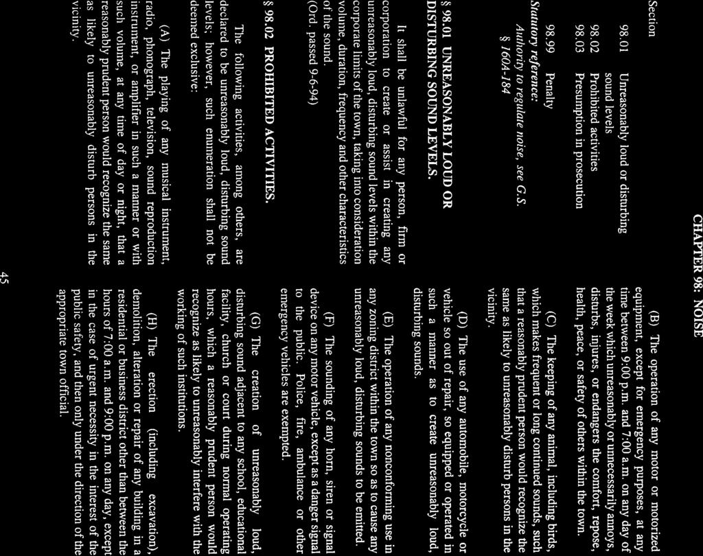
82
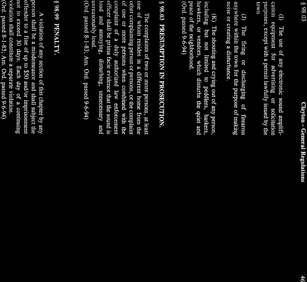
83
84
85
86
87
88
OSNI PONCA OFFICE REMODEL
 OSNI PONCA OFFICE REMODEL PROJECT MANUAL OCTOBER 2016 SCHEMMER PROJECT NO. 06571.002 OSNI PONCA OFFICE REMODEL TABLE OF CONTENTS DIVISION 00 - PROCUREMENT AND CONTRACTING REQUIREMENTS 000115 LIST OF DRAWING
BIDDING INFORMATION FOR HOLLY HILL ADMINISTRATION COMPLEX RENOVATION AND ADDITION. for the COUNTY OF ORANGEBURG. Project Number: FY
 BIDDING INFORMATION FOR HOLLY HILL ADMINISTRATION COMPLEX RENOVATION AND ADDITION for the COUNTY OF ORANGEBURG Project Number: FY13-1206 October 18, 2012 1180 Columbia Avenue Suite 201 29063 (803) 781-1451
ADDENDUM #3. GRW Project No.: Date: March 19, 2019 Subject: City of Nicholasville Fire Station #4
 ADDENDUM #3 GRW Project No.: Date: March 19, 2019 Subject: City of Nicholasville Fire Station #4 Please address inquiries to: Aaron R. Nickerson GRW, Inc. anickerson@grwinc.com TO ALL PROSPECTIVE BIDDERS:
CITY OF RICHMOND EDI BUILDING WINDOW REPLACEMENT PROJECT MANUAL. Commonwealth Architects
 CITY OF RICHMOND EDI BUILDING WINDOW REPLACEMENT 701 North 25th Street Richmond, Virginia 23223 PROJECT MANUAL PERMIT SET FEBRUARY 27, 2017 Commonwealth Architects 101 Shockoe Slip Richmond, VA 23219 CITY
The Home Depot U.S.A., Inc. Instructions to Bidders
 The Home Depot U.S.A., Inc. Instructions to Bidders Home Depot Page 1 of 5 Article 1 Definitions 1.1 Bidding Documents include the Bidding Requirements and the proposed Contract Documents. The Bidding
CITY OF RICHMOND EDI BUILDING WINDOW REPLACEMENT 701 North 25th Street Richmond, Virginia PROJECT MANUAL BID SET April 4, 2018
 CITY OF RICHMOND EDI BUILDING WINDOW REPLACEMENT 701 North 25th Street Richmond, Virginia 23223 PROJECT MANUAL BID SET April 4, 2018 Commonwealth Architects 101 Shockoe Slip, Fl 3 Richmond, VA 23219 CITY
DeKalb County Library Dunwoody Library Staff Area Renovation
 PROJECT MANUAL DeKalb County Library Dunwoody Library Staff Area Renovation OWNER: DeKalb County Library Email: kimbroj@dekalblibrary.org Contact: Jackee Kimbro 404-508-719-, ext. 2236 ARCHITECT: MEP ENGINEER:
1) Unified School District No. 489 reserves the right to reject any or all bids and to waive any informalities in the bid procedure.
 Unified School District No. 489 reserves the right to reject any or all bids and to waive any informalities in the bid procedure.") Prospective bidders: The Board of Education, Unified School District No. 489, will receive bids for the fabrication and construction of two pre-manufactured metal building in the designated area at the
Prospective bidders: The Board of Education, Unified School District No. 489, will receive bids for the fabrication and construction of two pre-manufactured metal building in the designated area at the
New Mexico State University Herritage Farm Interpretive Trail
 PROJECT MANUAL PROJECT MANAGER: SHELLEY ZIVKOVICH 575-646-1991 shelleyz@nmsu.edu New Mexico State University Herritage Farm Interpretive Trail APRIL 28, 2017 PROJECT #206-88 WDG ARCHITECTS 1014 South Main
Ogden Regional Medical Center Courtyard Remodel. Construction Documents. MountainStar Healthcare PROJECT MANUAL FOR
 PROJECT MANUAL FOR Ogden Regional Medical Center 5475 South 500 East Ogden, UT 84405 for MountainStar Healthcare Construction Documents NJRA Architects, Inc. 5272 South College Dr. Murray, Utah 84123 Telephone:
SSM Project: Centennial School District Issued for Bid AC Unit Replacements 05/16/2014 Klinger and Log College Middle Schools
 Division Section Title SPECIFICATIONS GROUP General Requirements Subgroup DIVISION 01 GENERAL REQUIREMENTS 011000 SUMMARY 012500 SUBSTITUTION PROCEDURES 012600 CONTRACT MODIFICATION PROCEDURES 012900 PAYMENT
Bidding Conditions. March 22, (Project# 0192) at the. Fresno Chaffee Zoo. Project : Warthog Exhibit. Located at. 894 West Belmont Avenue
 at the. Fresno Chaffee Zoo. Project : Warthog Exhibit. Located at. 894 West Belmont Avenue") Bidding Conditions March 22, 2018 (Project# 0192) at the Fresno Chaffee Zoo Project : Warthog Exhibit Located at 894 West Belmont Avenue Fresno, CA 93728 Page 1 of 8 DEFINITIONS Addendum - A document issued
Bidding Conditions March 22, 2018 (Project# 0192) at the Fresno Chaffee Zoo Project : Warthog Exhibit Located at 894 West Belmont Avenue Fresno, CA 93728 Page 1 of 8 DEFINITIONS Addendum - A document issued
The following shall be incorporated into the Contract Documents dated 12 MARCH 2018.
 ADDENDUM NO. 1 DATE: March 28, 2018 PROJECT: OWNER: BID DATE: L Anse Area Schools Concession Building L Anse Area Schools Monday, April 9, 2018 at 2:00 PM The following shall be incorporated into the Contract
RWA, Inc. TECHNICAL SPECIFICATIONS NORTH COLLIER BOULEVARD PAVING AND DRAINAGE IMPROVEMENTS Willow Park Drive Suite 200 Naples, FL 34109
 RWA, Inc. TECHNICAL SPECIFICATIONS NORTH COLLIER BOULEVARD PAVING AND DRAINAGE IMPROVEMENTS 6610 Willow Park Drive Suite 200 Naples, FL 34109 MAY 23, 2012 NORTH COLLIER BOULEVARD PAVING AND DRAINAGE IMPROVEMENTS
University of Oklahoma Sarkeys Energy Center Atriums Waterproofing Project mass project no Set no. project manual.
 University of Oklahoma Sarkeys Energy Center Atriums Waterproofing Project mass project no. 1801.01 07 12 2018 Set no. project manual. University of Oklahoma Sarkeys Energy Center Atriums Waterproofing
PAWLEYS ISLAND TOWN HALL
 DOCUMENT 001116 - INVITATION TO RE-BID 1.1 PROJECT INFORMATION A. Notice to Bidders: Prequalified bidders are invited to submit bids for Project as described in this Document according to the Instructions
TOWNES + architects, P.A.
 TOWNES + architects, P.A. 2421 North 12th Avenue, Pensacola, Florida 32503 Telephone: (850) 433-0203 Florida Registration AA-26001051 PROJECT MANUAL City of Pensacola Fleet Maintenace Garage Re ovation
GADSDEN ELEMENTARY SCHOOL PHOTOVOLTAIC SYSTEM PROJECT
 GADSDEN ELEMENTARY SCHOOL PHOTOVOLTAIC SYSTEM PROJECT JUNE 13, 2018 PROJECT MANUAL SAVANNAH-CHATHAM COUNTY PUBLIC SCHOOL SYSTEM DULOHERY WEEKS GADSDEN ELEMENTARY SCHOOL PHOTOVOLTAIC SYSTEM PROJECT TABLE
DEAN + TYLER + BURNS ARCHITECTURE
 DEAN + TYLER + BURNS ARCHITECTURE May 17, 2017 Community Safe Room for the City Springville 580 Indian Crest Drive Indian Springs, AL 35124 tel.: 205.427.7890 email: m@rchitecture-e.com ADDENDUM NO. 3
DIVISION 10 - SPECIALTIES Toilet, Bath, and Laundry Accessories Fire Extinguishers
 DIVISION 01 GENERAL REQUIREMENTS 012500 Substitution Procedures 012600 Contract Modification Procedures 013100 Project Management and Coordination 013150 Requests for Information 013200 Construction Progress
TRUMAN STATE UNIVERSITY SITE IMPROVEMENTS, KIRK BLDG, MISSOURI HALL & STUDENT REC CENTER LTD RENOVATIONS
 SECTION 011000 - SUMMARY PART 1 - GENERAL 1.1 RELATED DOCUMENTS A. Drawings and general provisions of the Contract, including General and Supplementary Conditions and other Division 01 Specification Sections,
OAK PARK HIGH SCHOOL. Planetarium Upgrade from Analog to Digital
 PROJECT MANUAL For OAK PARK HIGH SCHOOL Planetarium Upgrade from Analog to Digital OWNER: OAK PARK SCHOOLS 13900 Granzon Oak Park, MI 48237 ARCHITECT: 65 Market Street Mount Clemens, MI 48043 P. (586)
Bidding Conditions Attachment C
 Bidding Conditions Attachment C REV Date: November 9, 2018 Project Name (Permit Nos. xxx) at the Fresno Chaffee Zoo Project No. xxxx Located at 894 West Belmont Avenue Fresno, CA 93728 Page 1 of 8 DEFINITIONS
PROJECT MANUAL POINT BLANK RANGE & GUN SHOP. 600 Corporate way Knoxville, TN. Bid/Permit Set
 PROJECT MANUAL POINT BLANK RANGE & GUN SHOP 600 Corporate way Knoxville, TN Bid/Permit Set Division Section Title SPECIFICATIONS GROUP DIVISION 01 - GENERAL REQUIREMENTS 011000 SUMMARY 012600 CONTRACT
1ARCHITECTURE TABLE OF CONTENTS
 TABLE OF CONTENTS DIVISION 00 - PROCUREMENT AND CONTRACTING REQUIREMENTS 00 0102 COVER 00 0107 SEALS PAGE 00 0111 TABLE OF CONTENTS DIVISION 01 - GENERAL REQUIREMENTS 01 1000 01 2000 01 2100 01 2300 01
County of Elko, Nevada Requirements, Specifications and Contract Documents. Mechanical System Upgrade, Project Manuel. Jackpot, Elko County, Nevada
 1 County of Elko, Nevada Requirements, Specifications and Contract Documents for Jackpot Recreation Center Mechanical System Upgrade 2016 Project in Jackpot, Elko County, Nevada Department of Community
BOWIE STATE UNIVERSITY CAR PARKING LOT
 BOWIE STATE UNIVERSITY CAR PARKING LOT TECHNICAL SPECIFICATIONS 100% CD SUBMISSION NOVEMBER 2, 2018 Prepared by WHITNEY, BAILEY COX & MAGNANI, LLC 300 East Joppa Road, Suite 200 Baltimore, Maryland 21286
DOCUMENT BID PROPOSAL
 DOCUMENT 00 41 13 BID PROPOSAL TO: SAN JOSE / EVERGREEN COMMUNITY COLLEGE DISTRICT, a California Community College District, acting by and through its Board of Trustees ("the District"). FROM: (Name of
2. Clarification: The building address is 801 Henderson Street.
 East Energy Structural Steel Painting University of South Carolina Project Number H27-Z037 Addendum One October 19, 2015 NOTE: The following amendments, additions, and deletions shall be made to the Construction
Document B Standard Form of Agreement Between Owner and Architect, Construction Manager as Adviser Edition
 Document B132 2009 Standard Form of Agreement Between Owner and Architect, Construction Manager as Adviser Edition AGREEMENT made as of the in the year (In words, indicate day, month and year.) BETWEEN
1. Section "Temporary Facilities and Controls" for limitations and procedures governing temporary use of Owner's facilities.
 CSB 7th Floor Orthopaedic Surgery Office Renovation Phase 2 SECTION 011000 - SUMMARY PART 1 - GENERAL 1.1 RELATED DOCUMENTS A. Drawings and general provisions of the Contract, including General and Supplementary
VAE VIEW ELEMENTARY WINDOW REPLACEMENT West 1600 North Layton, UT Specifications. Construction Documents
 VAE VIEW ELEMENTARY WINDOW REPLACEMENT 1750 West 1600 North Layton, UT 84041 Specifications 19 March 2018 TABLE OF CONTENTS DIVISION 00 PREREQUIREMENT AND CONTRACTING REQUIREMENTS A101 A201 A310 A312 G701
ADDENDUM ITEMS: This addendum consists of 2 pages and the following attachments: Pre-Bid Conference Sign-in Sheets, and SE-330, Lump Sum Bid Form.
 1330 Lady St., Suite 500 (29201) P.O. Box 5695 Columbia, SC 29250 803 799 0247 p 803 771-6844 f Addendum No. 1 Project: Coastal Carolina University - University Place Dining Hall Project No.: C-805-15
707 Minnesota Ave., Suite 506 Kansas City, Kansas Tel Fax
 ADDENDUM 707 Minnesota Ave., Suite 506 Kansas City, Kansas 66101 Tel. 913.287.1900 Fax. 816.300.4102 www.wskfarch.com A r c h i t e c t u r e I n t e r i o r D e s i g n I l l u s t r a t I o n P l a n
LOS RIOS COMMUNITY COLLEGE DISTRICT 1919 Spanos Court, Sacramento, CA Phone (916) FAX (916) Purchasing Department
 FAX (916) Purchasing Department") Addendum 1 Text 5-9-17 LOS RIOS COMMUNITY COLLEGE DISTRICT 1919 Spanos Court, Sacramento, CA 95825 Phone (916) 568-3071 FAX (916) 568-3145 Purchasing Department Sacramento City College American River College
Addendum 1 Text 5-9-17 LOS RIOS COMMUNITY COLLEGE DISTRICT 1919 Spanos Court, Sacramento, CA 95825 Phone (916) 568-3071 FAX (916) 568-3145 Purchasing Department Sacramento City College American River College
RANDOLPH COMMUNITY CENTER GYMNASIUM FLOOR REPLACEMENT
 PROJECT MANUAL RANDOLPH COMMUNITY CENTER GYMNASIUM FLOOR REPLACEMENT CITY OF RICHMOND Richmond, Virginia Architect s Project No. 563107 ARCHITECT/ENGINEER RICHMOND, VIRGINIA A/E s Project No. 563107 set
1997 Part 2. Document B141. Standard Form of Architect's Services: Design and Contract Administration TABLE OF ARTICLES
 TM Document B141 Standard Form of Architect's Services: Design and Contract Administration 1997 Part 2 TABLE OF ARTICLES 2.1 PROJECT ADMINISTRATION SERVICES 2.2 SUPPORTING SERVICES 2.3 EVALUATION AND PLANNING
SPECIFICATIONS May 25, Ellicott Station Redevelopment Brewery Building - 40 Ellicott Street Ellicott Street Batavia, New York United States
 SPECIFICATIONS May 25, 2018 Ellicott Station Redevelopment Brewery Building - 40 Ellicott Street Ellicott Street Batavia, New York United States Ellicott Station Development, LLC 500 Seneca Street Suite
Both envelopes must have the following information in the lower left hand corner:
 SECTION 001116 INVITATION TO BID The City of Morgantown is requesting a bid for masonry restoration for the City Hall Building in Morgantown, WV. The Project is for building envelope rehabilitation including
Project Manual. Brooks Medical Office Building 323 East 100 North, Lehi, UT Lehi, UT 84043
 423 West 800 South, Suite A316 Salt Lake City, UT 84101 cell: 801.652.7171 email: nh@ratherarchitecture.com Project Manual Brooks Medical Office Building 323 East 100 North, Lehi, UT 84043 Lehi, UT 84043
PROJECT MANUAL VOLUME ONE EOP Project # August 17, 2018
 PROJECT MANUAL VOLUME ONE EOP Project # 201732 August 17, 2018 KCTCS System Office Renovation MECHANICAL ROOM EQUIPMENT DEMOLITION 300 N. Main St. Versailles, Kentucky 40383 ARCHITECT EOP Architects 201
Document B252TM 2007
 Document B252TM 2007 Standard Form of Architect s Services: Architectural Interior Design for the following PROJECT: (Name and location or address) This document has important legal consequences. Consultation
INSTRUCTIONS TO BIDDERS
 INSTRUCTIONS TO BIDDERS CONTENTS I. Bid Documents II. Ethical Business Practices III. Contractor Qualifications IV. Performance and Quality Standards V. Bid Evaluation VI. Contract Award VII. Work Operations
CONSTRUCTION DOCUMENTS Part 1
 Audio Presentation Session 4 CONSTRUCTION DOCUMENTS Part 1 Project Delivery Education Program Construction Document Technology (CDT) Preparatory Course 2011 The Construction Specifications Institute www.csinet.org
Coastal Carolina University RE-BID WILLIAMS BRICE RENOVATION AND REPAIR Conway, South Carolina
 Project Manual for Coastal Carolina University RE-BID WILLIAMS BRICE RENOVATION AND REPAIR Conway, South Carolina DWG Consulting Engineers 1009 Anna Knapp Blvd. Suite 202 Mt Pleasant, South Carolina 29464
NORTHWESTERN UNIVERSITY PROJECT NAME JOB # ISSUED: 03/29/2017
 SECTION 01 3100 - PROJECT MANAGEMENT AND COORDINATION PART 1 - GENERAL 1.1 RELATED DOCUMENTS A. Drawings and general provisions of the Contract, including General and Supplementary Conditions and other
This is EXHIBIT A, consisting of [ ] pages, referred to in and part of the Task Order dated [ ]. Engineer's Services for Task Order
![This is EXHIBIT A, consisting of [ ] pages, referred to in and part of the Task Order dated [ ]. Engineer's Services for Task Order](/thumbs/83/88517393.jpg "This is EXHIBIT A, consisting of [ ] pages, referred to in and part of the Task Order dated [ ]. Engineer's Services for Task Order") This is EXHIBIT A, consisting of [ ] pages, referred to in and part of the Task Order dated [ ]. Engineer's Services for Task Order [Introductory Note to User: The following text as published describes
This is EXHIBIT A, consisting of [ ] pages, referred to in and part of the Task Order dated [ ]. Engineer's Services for Task Order [Introductory Note to User: The following text as published describes
Main Building Auditorium
 Main Building Auditorium Theatre and Lighting Upgrade Moberly Area Community College 101 College Avenue Moberly, Missouri This document contains all necessary instructions and specifications to perform
This Addendum is directed to all prime Contract Bidders, and all others to whom Drawings and Specifications have been issued by the Architect.
 North Campus Entrance and related work Wallace State Community College ADDENDUM 3 PART 1 - GENERAL Project: North Campus Entrance and related work [B.C. # 2016259] Owner: Wallace State Community College
City of Eagle Point 2017 Paving Instruction to Bidders
 City of Eagle Point 2017 Paving Instruction to Bidders Issued: August 2, 2017 Closing Date and Time: Wednesday August 16, 2016 at 2:00 pm Project Summary The City of Eagle Point is requesting bids for
1. Section "Temporary Facilities and Controls" for limitations and procedures governing temporary use of Owner's facilities.
 SECTION 011000 - SUMMARY PART 1 - GENERAL 1.1 RELATED DOCUMENTS A. Drawings and general provisions of the Contract, including General and Supplementary Conditions and other Division 01 Specification Sections,
Beverly Gardens Park City of Beverly Hills, CA. Block #9: Elm Foothill Garden
 Beverly Gardens Park Block #9: SPECIFICATIONS 100% CD / BID SET TABLE OF CONTENTS DIVISION 01 GENERAL REQUIREMENTS SECTION No. TITLE 011000.Summary. 3 012213.Unit Prices...1 012500.Substitution Procedures
City of Eagle Point South Shasta Pedestrian Bridge Instruction to Bidders
 City of Eagle Point South Shasta Pedestrian Bridge Instruction to Bidders Issued: November 15, 2017 Closing Date and Time: January 16, 2018, at 2:00 pm Project Summary The City of Eagle Point is requesting
REVISED BID FORM. To Procurement Services, Room 1104, 900 East Broad Street, Richmond, Virginia:
 REVISED BID FORM SEALED BIDS WILL BE RECEIVED at the Department of Procurement Services, City Hall, 900 E. Broad Street, Rm. 1104, Richmond, Virginia 23219, UNTIL BUT NOT LATER THAN 2:30 P.M. ON February
The bid is being postponed to comply with State rules requiring 4 calendar days for receipt of bids after an addendum.
 ADDENDUM NO. FOUR March 5, 2018 NORTH IDAHO COLLABORATIVE EDUCATION BUILDING North Idaho College, Coeur d Alene, ID DPW PROJECT 16251 - H2A PROJECT 1616 This addendum is hereby incorporated into and is
REQUEST FOR PROPOSAL FOR CONSTRUCTION MANAGEMENT SERVICES NOT AT RISK FOR THE. St. Charles County Ambulance District
 REQUEST FOR PROPOSAL FOR CONSTRUCTION MANAGEMENT SERVICES NOT AT RISK FOR THE St. Charles County Ambulance District Base 3 & Training Facility Construction 4169 Old Mill Parkway St. Peters, MO 63376 September
ADDENDUM NO. 1 CONTRACT NO. TU-191 SALT STORAGE BUILDING FOR THE TOWN OF ULSTER ULSTER COUNTY, NEW YORK. January 25, 2019
 DENNIS M. LARIOS, P.E. CHRISTOPHER J. ZELL, L.L.S. Lic. No. 58747 Lic. No. 49629 BRINNIER and LARIOS, P.C. PROFESSIONAL ENGINEERS & LAND SURVEYORS 67 MAIDEN LANE DESIGN KINGSTON, NEW YORK 12401 SUBDIVISIONS
Invitation for Bid - Standard Office Furniture / Task Chair
 Invitation for Bid - Bid#2016-09-001 Instructions to Bidders 1. General Information Rice University is issuing this Invitation for Bid (IFB) for the procurement of goods and/or trade services as described
Attached please find the revised Plan Sheet C3 Proposed Conditions Plan.
 ADDENDUM NO. 1 124002-4A RE: FROM: TO: Depot Street Drainage Improvements Charlestown, New Hampshire DuBois & King, Inc. P.O. Box 339 Randolph, Vermont 05060 (802) 728-3376 Prospective Bidders DATE: June
I. CHANGES TO THE SPECIFICATIONS REISSUED WITH THIS ADDENDUM
 I. CHANGES TO THE SPECIFICATIONS REISSUED WITH THIS ADDENDUM A. Delete the following pages and substitute the new pages which are attached and made a part of this Addendum. Changes to existing contract
RICHMOND PUBLIC SCHOOLS
 PROJECT MANUAL RICHMOND PUBLIC SCHOOLS NEW MIDDLE SCHOOL CONSTRUCTION ON HULL STREET CONSTRUCTION PROJECT DEPT. OF EDUCATION NO. 123-108-00-100 DIVISION 1 (DRAFT SPECIFICATIONS) PREPARED BY RRMM ARCHITECTS
RICHMOND PUBLIC SCHOOLS
 PROJECT MANUAL RICHMOND PUBLIC SCHOOLS E.S.H. GREENE ELEMENTARY SCHOOL CONSTRUCTION PROJECT DEPT. OF EDUCATION NO. 123-144-00-100 DIVISION 1 (DRAFT SPECIFICATIONS) PREPARED BY RRMM ARCHITECTS ARCHITECTURE
City of Jacksonville Finance Department
 City of Jacksonville Finance Department # 1 Municipal Drive Office Phone: (501) 982-4502 P.O. Box 126 Fax Number: (501) 985-9768 Jacksonville, AR. 72076 E-Mail: rbest@cityofjacksonville.net Cheryl Erkel
Chapter 6, Construction
 Chapter 6, Construction CHAPTER CONTENTS 6.1 OWNER-CONTRACTOR AGREEMENT A. Preparation B. Owner Signature C. Award 6.2 PRE-CONSTRUCTION CONFERENCE A. Administration B. Attendees C. Pre-Construction Conference
CITY OF PANAMA CITY BEACH WWTF INFLUENT SCREENS REPLACEMENT April 14, 2017
 CITY OF PANAMA CITY BEACH WWTF INFLUENT SCREENS REPLACEMENT April 14, 2017 ADDENDUM NO. 1 (This Form Must Be Signed and Submitted With Bid Form) Addendum No. 1 addresses the following issues: QUESTIONS
ASPIRE HEALTH PARTNERS. Project Specifications. Patient Tower Reroof 1800 Mercy Drive Orlando, Florida August 31, 2016
 ASPIRE HEALTH PARTNERS Patient Tower Reroof 1800 Mercy Drive 32808 Project Specifications August 31, 2016 RS&H, Inc. 301 East Pine Street, Suite 350 32801 (407) 893.5800 RS&H Project # 504-0052-000 TABLE
ADDENDUM NO. 3. Item 3 NOTICE OF OPPORTUNITY - REPLACE in its entirety with the attached ***REVISED 08/03/2018
 Construction Contracts Administration, Procurement Contracts & Materials Management (PCMM) Oregon State University 644 SW 13 th Ave. Corvallis, Oregon 97333 P 541-737-4261 F 541-737-5546 oregonstate.edu
CHAPEL HILL TOWN HALL RENOVATIONS UPPER LEVEL, SOUTH CHAPEL HILL, NORTH CAROLINA
 SECTION 011000 - SUMMARY PART 1 - GENERAL 1.1 RELATED DOCUMENTS A. Drawings and general provisions of the Contract, including General and Supplementary Conditions and other Division 01 Specification Sections,
Blatt PE Center Fire Alarm Upgrades November 12, 2012 State Project No. H27-I851-B
 Blatt PE Center Fire Alarm Upgrades November 12, 2012 State Project No. H27-I851-B Addendum No. 2 TO: ALL BIDDERS OF RECORD The following items shall take precedence over the drawings and specifications
Appendix D University of Maine System. Supplementary Requirements to AIA Document B Standard Form of Architect s Services
 Appendix D University of Maine System Supplementary Requirements to AIA Document B201-2007 Standard Form of Architect s Services This document provides the Architect s scope of services only and must be
ADDENDUM #1 Construction Support Services for the Water Treatment Plant Project PW
 January 31, 2018 To Whom It May Concern: I. INSTRUCTIONS ADDENDUM #1 Construction Support Services for the Water Treatment Plant Project 18-0018PW A. The following additions, deletions, revisions, and/or
NMSU Carlsbad Campus Main Building and Computer Building DDC Control Upgrade. Project Manual Technical Specifications Review Submittal May 12, 2017
 NMSU Carlsbad Campus Main Building and Computer Building DDC Control Upgrade NMSU Facilities and Services Department P.O. Box 30001 Las Cruces, NM 88003-8001 Project Manual Technical Specifications Review
Hard Rock Hotel and Casino - Tulsa Casino 3 and Suite Hotel Exterior Painting Bid Issue Issue Date: 18 March 2013 Project Number
 Hard Rock Hotel and Casino - Tulsa Casino 3 and Suite Hotel Exterior Painting Issue Date: 18 March 2013 Project Number 13-201.1 9400 Gateway Drive, Suite B Reno, NV 89521 775.852.3977 (p) 775.852.6543
DIVISION 1 GENERAL REQUIREMENTS SECTION PROJECT SCHEDULE
 DIVISION 1 GENERAL REQUIREMENTS SECTION 01 32 16 PART 1 - GENERAL 1.1 RELATED DOCUMENTS A. All drawings and technical specifications, Notice to Bidders, Instructions and Information to Bidders, Bid Proposal
LCCC MAIN PLANT BOILER BURNER UPGRADES
 LCCC MAIN PLANT BOILER BURNER UPGRADES FOR Laramie County Community College (LCCC) 1400 East College Drive Cheyenne, WY 82007 ENGINEERS Cator, Ruma & Associates 420 West Lincolnway Cheyenne, WY 82001 PROJECT
AGENDA. PRE-BID / SITE VISIT MEETING Tuesday, August 7, 2018, 9:00 am
 AGENDA PRE-BID / SITE VISIT MEETING Tuesday, August 7, 2018, 9:00 am Project #217090 & 218041 Britt Place Washout / Precinct Road Washout CBJTC, Starke, FL 1. SIGN-IN OF ALL ATTENDEES: 2. INTRODUCTIONS:
DAG Architects, Inc. July South Walton Fire District Fleet Maintenance/Logistics Building & Training Tower
 DOCUMENT 001153 - REQUEST FOR QUALIFICATIONS 1.1 PURPOSE, LAWS, AND REGULATIONS A. The purpose of the Prequalification Procedure described in this Document is to provide Owner with a mechanism to evaluate
Memphis Housing Authority Capital Improvements Department 700 Adams Street, Room 107 Memphis, Tennessee
 Memphis Housing Authority Capital Improvements Department 700 Adams Street, Room 107 Memphis, Tennessee 38105-5029 ADDENDUM NO. 2 Issued: March 6, 2018 This addendum shall become and form a part of the
DOCUMENT BID FORM - STIPULATED SUM (MULTIPLE-PRIME CONTRACTS) Bidder:.
 Bidder:.") DOCUMENT 004120 - BID FORM - STIPULATED SUM (MULTIPLE-PRIME CONTRACTS) BID INFORMATION Bidder:. Project Name: Remodeling for Urban Style Apartments 409 N. Broadway Green Bay, WI 54303 Owner: Architect:
DOCUMENT 004120 - BID FORM - STIPULATED SUM (MULTIPLE-PRIME CONTRACTS) BID INFORMATION Bidder:. Project Name: Remodeling for Urban Style Apartments 409 N. Broadway Green Bay, WI 54303 Owner: Architect:
Answer 1: The reference to CB 5 is incorrect. The correct reference should be CB 4. Question 2: Have any potential staging areas been identified?
 ADDENDUM NO. 1 July 26, 2017 223837 RE: FROM: TO: CITY OF BARRE HMGP STORM DRAIN IMPROVEMENT PROJECTS DuBOIS & KING, INC. P.O. Box 339 Randolph, Vermont 05060 (802) 728-3376 Prospective Bidders This Addendum
Addendum No. 1 Page 1 of 2
 Addendum No. 1 Page 1 of 2 DATE: March 14, 2016 Joliet Junior College 1215 Houbolt Road Joliet, IL 60431 TO: Prospective Bidders SUBJECT: Addendum No. 1 PROJECT NAME: Parking Lot S7 Improvements JJC PROJECT
JEFCO GYM HVAC ADDITIONS TO ARCHITECT'S NO AES, BES, CES, PGES, SRES B.C. NO
 JEFCO GYM HVAC ADDITIONS TO ARCHITECT'S NO. 2825 AES, BES, CES, PGES, SRES B.C. NO. 2018554 DOCUMENT 00 9113A - ADDENDUM NO. A 1.1 PROJECT INFORMATION A. Project Name: JEFCO Gym HVAC Additions to AES,
GENERAL REQUIREMENTS
 CITY OF BRAMPTON LANDSCAPE SPECIFICATIONS SECTION 01001-1 PART 1 GENERAL 1.1 Work Covered By Contract Documents.1 Work covers, in general terms: demolition, removals, site preparation and complete construction
University Apartments on Brooklyn PROJECT MANUAL
 Section 011000 - Summary PART 1 - GENERAL 1.1 SUMMARY A. Section Includes: 1. Project information. 2. Work covered by Contract Documents. 3. Phased construction. 4. Work under separate contracts. 5. Access
CITY OF MARSHALL, MINNESOTA
 Office of the Director of Public Works/City Engineer 344 West Main Street Marshall, MN 56258 507-537-6773 Fax: 507-537-6830 CITY OF MARSHALL, MINNESOTA SPECIFICATION AND BIDDING DOCUMENTS FOR REMOVAL OF
A D D E N D U M. REPLACE: Project Summary with attached revised Project Summary. 1 Specification Section Project Summary
 A D D E N D U M 1 TO All Plan Holders ISSUE DATE 20 January 2017 PROJECT # 15-028 REGARDING Switchgear Replacement NARRATIVE PAGES 1 15-02812 KVa Switchgear Replacement Project SPECIFICATION PAGES 10 DRAWING
IBMF STATE OF GOOD REPAIR UPGRADES
 IBMF STATE OF GOOD REPAIR UPGRADES City of North Las Vegas, Nevada SPECIFICATIONS For 14-092 December 26, 2013 TABLE OF CONTENTS SECTION 01100 SECTION 01250 SECTION 01290 SECTION 01310 SECTION 01322 SECTION
Refer to Section Proposal Form/All Trades (issued) a. Revised Alternate No. 2 b. Added Alternate No. 3
 a. Revised Alternate No. 2 b. Added Alternate No. 3") WAKELY ASSOCIATES, INC. ADDENDUM NO. ONE ARCHITECTS 30500 Van Dyke Avenue Suite 209 Warren, Michigan 48093 NEW LED LIGHTING Page 1 of 1 (write up only) January 23, 2018 ADDENDUM NO. ONE to the plans and
WAKELY ASSOCIATES, INC. ADDENDUM NO. ONE ARCHITECTS 30500 Van Dyke Avenue Suite 209 Warren, Michigan 48093 NEW LED LIGHTING Page 1 of 1 (write up only) January 23, 2018 ADDENDUM NO. ONE to the plans and
Sunnycrest Manor Roosevelt Street Dubuque, IA Sunnycrest Manor Kitchen Ventilation MEP Engineers Project #1735
 Sunnycrest Manor 2375 Roosevelt Street Dubuque, IA 52001 Sunnycrest Manor Kitchen Ventilation MEP Engineers Project #1735 Sunnycrest Manor Kitchen Ventilation SUNNYCREST MANOR KITCHEN VENTILATION 2375
REQUEST FOR PROPOSAL. Construction Management Services Not at Risk
 REQUEST FOR PROPOSAL Construction Management Services Not at Risk The St. Charles County Ambulance District proposes to retain a qualified firm/team for the Construction Management Services Not at Risk
I INVITATION TO BID City of Fort Morgan Water Distribution Department Waterline Isolation Project
 I INVITATION TO BID Water Distribution Department The Water Distribution Department is accepting sealed bids for a until 2:45 p.m. (our clock) on March 8, 2018 at City Hall located at 110 Main Street,
STANTEC ARCHITECTURE ARCHITECTS PLANNERS ENGINEERS 3001 Bee Caves Road Suite 300 Austin, TX April 29, 2016
 ADDENDUM NUMBER ONE TO PLANS AND SPECIFICATIONS FOR ELGIN HIGH SCHOOL CTE CANOPY ADDITION ELGIN INDEPENDENT SCHOOL DISTRICT STANTEC ARCHITECTURE ARCHITECTS PLANNERS ENGINEERS 3001 Bee Caves Road Suite
Audio Sessions. Session 4 PROCUREMENT. Construction Contract Administration Education Program
 Audio Sessions Session 4 PROCUREMENT Construction Contract Administration Education Program Certified Construction Contract Administrator (CCCA) Preparatory Course 2011 The Construction Specifications
Owner: Metropolitan Park District of Tacoma
 Metropolitan Park District of Tacoma STAR Center HVAC Improvements SWR Bid# J2016-08 In TACOMA, WASHINGTON CONTRACT DOCUMENTS Owner: Metropolitan Park District of Tacoma Planning, Design and Development
CONTRACTOR S PROPOSAL
 WEST VIRGINIA DEPARTMENT OF TRANSPORTATION DIVISION OF HIGHWAYS ALL ITEMS MUST BE COMPLETED BY CONTRACTOR CALL NUMBER CONTRACTOR S NAME CONTRACTOR S FEIN BID AMOUNT DBE GOAL (%) WV LICENSE NUMBER PREQUALIFICATION
Amphitheater High School Roof Replacement
 Amphitheater Public Schools Amphitheater High School Roof Replacement BG Project No: 17.14.06 Construction Document Specifications Amphitheater High School Roof Replacement SPECIFICATIONS INDEX DIVISION
Plainview ISD High School Addition and Renovations 1501 Quincy Avenue Plainview, Texas
 August 8, 2011 Plainview ISD High School Addition and Renovations 1501 Quincy Avenue Plainview, Texas Chapman Harvey Architects, Inc. 612 Broadway Lubbock, Texas 79401 806-749-1153 CHA, Inc. Project #1029
SECTION SUPPLEMENTARY GENERAL CONDITIONS
 SECTION 00800 SUPPLEMENTARY GENERAL CONDITIONS PART 1 - GENERAL 1.1 SCOPE OF WORK In general, the Work consists of application of a fluid applied membrane, installation of new tapered insulation, installation
THE FORUM ROME, GEORGIA FOR FLOYD COUNTY PROJECT MANUAL (BALLROOM AND CONCESSIONS) Construction Documents
 Construction Documents") THE FORUM ROME, GEORGIA FOR FLOYD COUNTY PROJECT MANUAL (BALLROOM AND CONCESSIONS) Construction Documents Architect s Project Number: 420.01.01 Issued: November 11, 2016 PEACOCK a r c h i t e c t s 5525
THE FORUM ROME, GEORGIA FOR FLOYD COUNTY PROJECT MANUAL (BALLROOM AND CONCESSIONS) Construction Documents Architect s Project Number: 420.01.01 Issued: November 11, 2016 PEACOCK a r c h i t e c t s 5525
NOTICE TO PROSPECTIVE BIDDERS REGARDING PRE-QUALIFICATION FOR CONTRACTS FOR ALISAL UNION SCHOOL DISTRICT. Revised February 11, 2015
 NOTICE TO PROSPECTIVE BIDDERS REGARDING PRE-QUALIFICATION FOR CONTRACTS FOR ALISAL UNION SCHOOL DISTRICT Revised February 11, 2015 For Projects to be bid from February 12, 2015 to February 11, 2016 Alisal