StrongSeam SSFF1 Panel
|
|
|
- Dwight O’Connor’
- 6 years ago
- Views:
Transcription


 0.875 0.9375 26 ga.")


1 StrongSeam SSFF1 Panel Installation Manual May TO 24 COVERAGE CLIP OFFSET STRIATED PANEL (2 STRIATION BEADS ON PANEL) ga. & 24 ga. UL90 #529 UL2218 Class IV/Impact UL790 Class A/Fire Tulsa, OK Kansas City, KS
2 Design Guidelines This manual contains guidelines for installing Metal Panels Inc. (MPI) panels and trim. Guidelines presented herein were in effect as of this printing. Metal Panels Inc. reserves the right to change designs or specifications at any time in order to stay current with building code requirements. To ensure that you have the latest information, please contact your sales representative at Metal Panels Inc. Application and design illustrations are for your reference only, and may not be appropriate or specified for all environments, conditions or building designs. It is strongly recommended that all projects should be engineered and installed to conform to applicable building codes, regulations and accepted industry practices. A roof must be designed to support certain minimum wind and snow loads. Consult local building officials to determine appropriate design load requirements. All roof systems should be designed or verified by a qualified engineer. It is the buyer s responsibility to verify all code requirements, checking all measurements, and determine suitability of the product for the job. The buyer is responsible for supplying and confirming all actual length and quantities needed. All MPI instructions for this panel assume that a qualified firm or individual has been contracted to install this product. Failure to comply with stated recommendations voids all manufacturer responsibility for any damage or deterioration due to misuse of the product and voids any applicable warranty. 2
3 TABLE OF CONTENTS 1 Design Guidelines... 2 Table of Contents... 3 Introduction to Installation... 4 Storage & Handling... 6 Design & Installation Standard Trim Accessories Preliminary Installation Guide General Installation Overview Trim Installation Overview Visual Guide: Drip Edge Visual Guide: Rake Trim Visual Guide: Sidewall Trim Visual Guide: Endwall Trim Visual Guide: Valley Visual Guide: Pitch Change Visual Guide: Ridge Cap Visual Guide: Vented Ridge Cap Contact MPI
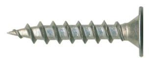
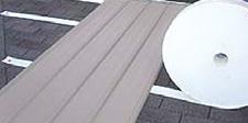
4 INTRODUCTION TO INSTALLATION Introduction The SSFF1 Panel is an economical snaptogether panel with a 1 standing seam for use over a solid deck. Panels are installed by using a pancake fastener in the panel s fastener flange. Specifications The StrongSeam SSFF1 Panel is available in both 26 ga. WeatherXL and 24 ga. Kynar with widths ranging from 12 to 24. MPI stocks eight colors for 16 wide panels in 26 ga. WeatherXL. Minimum recommended slope is 3:12. Pan striations are required for all 26 ga. panels. Maximum panel lengths are constrained only by practical handling and transportation limitations, typically a maximum of 55 ft. Panels exceeding 55 ft. will be roll-formed at the jobsite. fig. 1 Testing CLIP OFFSET UL90 #169 Uplift Rating 12 TO 24 COVERAGE STRIATED PANEL (2 STRIATION BEADS ON PANEL) 26 ga. & 24 ga. UL2218 Class IV/Impact Resistance UL790 Class A/Fire Resistance UL90 #529 UL2218 Class IV/Impact UL790 Class A/Fire Recommended Tools Cordless Screw Gun Snips Tape Measure Electric Metal Shear or Circular Saw Caulk Gun Pop Rivet Tool Chalk Line Duckbill Locking Pliers Hemming Tool Electrical Extension Cord Installer must have experience using the tools listed above for metal roofing installation. Safety Use extreme caution when walking on a metal roof. Metal panels may become slippery, so always wear shoes with non-slip soles. Avoid working on metal roofs during wet conditions. Do not walk on a metal roof which does not have a solid deck beneath it. If you must, walk on the purlins only. Always use appropriate safety harnesses. OSHA safety regulations should be complied with at all times. Caution Always wear heavy gloves when working with steel panels to avoid cuts from sharp edges. When power cutting or drilling steel panels, always wear safety glasses to prevent eye injury from flying debris. 4


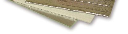
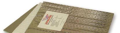
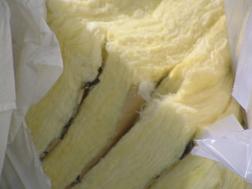
5 Production Lead Time Please consult your MPI sales representative for accurate order production time. Large orders, non-standard colors or custom panel fabrication may require longer lead times. Packaging For standard orders, panels are crated for truck shipment. Custom shipping requirements may be accommodated at an additional charge. (Illustration to demonstrate packaging methods only.) 5
6 STORAGE & HANDLING Storage When metal panels will NOT to be used immediately, store inside in a well-ventilated, dry location. Outdoor storage is not recommended and may void warranties; to do so is at the customer s own risk. Standing Seam panels are shipped with a plastic peel-off protective film, which should be removed shortly after taking receipt of the panels. Panels left in the sun, or stored for an extended amount of time may cause the protective film to permanently bond to the panel paint. Extended storage of crated panels is not recommended. Panels must not be stored near or come in contact with salt water, corrosive chemicals, ash, or solvent fumes, or come in contact with wet or green lumber If panel crates must be stored outside, strictly adhere to these requirements: 1. Storage area should be level, and should be located to minimize handling of crate during construction. 2. For storage on bare ground, place a plastic ground cover as a barrier under the crate to minimize exposure to moisture, dirt or dust from the soil. 3. Store crate above the ground by a minimum of 6 to allow air circulation beneath the crate, and to prevent damage from rising water. 4. Inspect stored crate frequently and repair any tears or punctures in the water-resistant cover with a compatible waterproof tape. 5. Re-cover opened crate at the end of each day to prevent entry of moisture and exposure to sunlight. 6

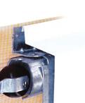
7 STORAGE & HANDLING Protective Film Removal Painted panels may have a protective film layer applied to the outside finish to prevent possible damage to the painted surface. Remove the protective film layer promptly, before exposing to direct sunlight and high temperatures. After exposure to heat or sunlight, the protective film cannot be removed. Never leave the protective film on the panels after installation. Metal Panels Inc. cannot be held liable for damage to metal caused by improper storage and failure to remove protective film. Some Safety Precautions To prevent injury, always wear gloves when working with steel panels. Wear safety glasses when cutting or drilling steel panels, and remove any metal shavings immediately to reduce risk of eye injury from flying debris. Avoid walking on metal panels; If you must walk on a metal roof, use extreme caution. Wear shoes with non-slip soles, for metal panels can become slippery even dry. Avoid working on metal roofs during wet conditions when the panels can become extremely slick. Walking or standing on a metal roof which does not have a solid deck beneath it is not recommended. If unavoidable, always walk on the purlins, never between. Do not for any reason walk on a roof made of material thinner than 29 gauge. Roof Storage For convenient handling, MPI SSFF1 panel crates can be lifted and placed on the roof. When lifting crated sheets, make sure they are adequately supported. Panels less than 20 ft. in length may be lifted with a forklift. When lifting panels in excess of 20 ft., it is recommended that a spreader bar with slings be used, or use two forklifts. When lifting, do not leave more than 1/3rd of the panel length unsupported. (See fig. 2) Determine best location for crate placement by how much area that crate of panels will cover. Crates should be placed on the roof facing the same direction that the panels will be installed. Make certain to keep the area clear for your markings and string lines that verify squareness of roof. Fig. 2 7


8 STORAGE & HANDLING Receiving Materials The installer has the responsibility to unload material from the delivery truck. The installer must provide suitable equipment for safely unloading all materials from the delivery truck. After receiving your order, verify the condition of the material and compare the shipment against the shipping list to ensure all ordered items have been received. If damages or shortages are discovered, note the discrepency on the shipping copy at time of delivery. If replacement material is required, you must contact Metal Panels Inc. to place the order. Report any damages or shortages to Metal Panels Inc. within 48 hours from the time of shipment. Caution Improper loading and unloading of crate may result in bodily harm and/or material damage. Metal Panels Inc. is not responsible for bodily injuries and/or material damages resulting from improper loading or unloading. General Handling Each crate should be handled with care to avoid product damage. Proper handling should be used to prevent bending panels or scratching the finish. To prevent panel damage, follow these steps for unloading and handling crate: 1. Crate should remain unopened and intact during any handling and remain so until the panels are ready to be installed. 2. Always lift crate as close as possible to its center of gravity 3. When lifting by crane, use a spreader bar of appropriate length and nylon band slings. (Do not use cable slings. They will damage panels.) 4. A panel crate of manageable length may be lifted by forklift. Set forklift forks to their maximum spacing apart, and center the load on the forks to prevent panel damage. Never lift a panel by its ends. Carry a panel by its longitudinal edge and in a vertical (not flat) position. For panels over 10 ft., two or more people should lift and carry the panel from the same edge. (see fig. 3) 5. Once a crate is opened, individual panels must be handled with care to prevent panel buckling or finish damage. 6. Gloves must always be worn when handling panels. fig. 3 8
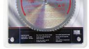
9 STORAGE & HANDLING Mechanical Handling Using a Forklift A forklift may be used for panels up to 20 ft. Set the forks at their maximum separation and center the load on the forks. When transporting crate across rough terrain, or over a long distance, use nylon straps or similar means of additional support for the crate. Never transport open crate. Using a Crane For lifting panel crate greater than 20 ft. in length, a crane is recommended, or two forklifts. Utilize an appropriate spreader bar to ensure even distribution of the weight to the lift points. No more than 1/3rd of the length of the panel should be left unsupported when lifting panel crate. Canvas or nylon slings should be used to lift panels. DO NOT use cable or chains they will damage the panels. Foot Traffic Walking on a metal roof can cause distortion of panels and damage to the finish. Foot traffic on an installed roof system must be kept to an absolute minimum. If continuous foot traffic is necessary for maintenance over the roof, then a permanent walkway should be installed. For foot traffic during installation, provide walking platforms to avoid any panel damage. If walking on the roof panels is unavoidable, walk only in the flats of the panel; walking on the ribs can damage the panels. Metal roof installers must be in full compliance with all applicable safety regulations including OSHA regulations. Field Cutting Caution Tin snips, portable shear or a nibbler type electric tool are recommended for field cutting StrongSeam SSFF1 panels. If a skill saw is used, the blade will generate slivers of metal chips. Any metal chips must be immediately removed from the panel because they will damage the finish and induce rust staining. One approach to addressing this problem is to flip the panels over when cutting. The metal slivers can be brushed away from the back side, preventing finish damage to the top side of the panels. Caution All roof or panel surfaces must be free of debris at all times. Installed surfaces should be wiped clean at the end of each work day. Never cut panels over other metal surfaces. Metal shavings will rust on the surface which will void the warranty. Always wear goggles for eye protection when cutting metal panels. 9


10 STORAGE & HANDLING Touch-up Paint All painted panels, trim and flashings have a factory-applied heat-cured finish. During handling and installation, a panel may become slightly scratched or nicked. Brush-on touchup paint is available in matching colors. It is recommended that a very small brush be used to apply touch-up paint only to those areas that are in need of repair (apply touch-up paint to the scratch itself. Do not paint over panel finish). Be aware that touch-up paint does not have the superior chalk and fade resistance of the factory-applied finish and will likely discolor at an accelerated rate. Avoid using aerosol paint because of the reduced durability and significant overspray that may occur. Periodic touch-up may be required to maintain color match. Due to the limitations and formulation of field-applied touch-up paint, there is no warranty offered for color match or durability of the product. When touching up scratches in panels or flashing, it is VERY IMPORTANT not to over paint the area to be touched up. Because of the curing solvent which must be added, air-dry formula touchup paint WEATHERS DIFFERENTLY than the thermoset formula paint which is applied on the coil coating line. For this reason, large brush strokes will create an unsightly appearance and will worsen over time, becoming aesthetically unacceptable. Use an Artist s Brush with a fine Liner point. Select the correct Touch-Up Paint to match roof panel or trim. Shake paint bottle thoroughly for at least 2 minutes to insure accurate color match. Test for color match on a small area out of line of sight. Allow to dry completely. Apply a fine line of paint to scratch area only - do NOT overpaint or blend. Please see MPI s Touchup Paint Flyer for complete instructions. 10
11 DESIGN & INSTALLATION Design Considerations Insulation & Ventilation Properly designed and installed vapor barriers and ventilation systems prevent condensation and the resulting moisture damage and loss of insulation efficiency. When highly-humid air contacts building surfaces that are below the dew point temperature of the air, condensation will occur. Proper insulation can provide resistance to heat transfer and protection against condensation forming on cooler surfaces within the building or the roof system. The building designer is responsible to specify an appropriate vapor retarder and insulation system for the project. Basic guidelines for control of condensation are as follows: 3. Seal all seams and penetrations of the vapor barrier in order to provide a continuous membrane to resist the passage of water vapor. 4. Structure ventilation contributes significantly to reducing condensation. Whether by passive or active (powered) venting, air movement to the outside of the building reduces interior vapor pressure. Buildings with attic space or retrofitted metal roofing system require vents at the eaves and peak of the roof in order to prevent a buildup of moisture under the roof. Check local building codes for proper ventilation practices for your area. 1. Faced insulation (insulation with vapor retarder) should be installed with the facing toward the warm side of the insulated area, typically, the interior of a building. 2. Insulation R-value must be high enough to maintain the temperatures of the vapor retarder above the interior dew point, using worst-case outside temperatures for a reference RIDGE VENT ATTIC INSULATION VENT AT EAVE 11
12 DESIGN & INSTALLATION Roofing Substrates In warm weather climates, synthetic underlayment should be used over the existing decking. The high temperature resistance prevents it from sticking to the panels and tearing, which can occur with asphalt-based felt paper. Roof Pitch Chart Reference the chart below for specifying StrongSeam SSFF1 panels and trims. fig. 4 In colder climates, ice and water shield should be used at the valley and eave. Apply over the decking before installation of the synthetic underlayment. L H Caution Use appropriate safety precautions when applying synthetic substrates because they can be slippery. (L) x (H) [Hip/Valley] S Peak Eave F (F) x (Pitch Factor)=S PITCH PITCH FACTOR HIP/VALLEY FACTOR PITCH PITCH FACTOR HIP/VALLEY FACTOR 3: : : : : : : : : :
13 STANDARD TRIMS 2.0 RIDGE J METAL RAKE J-CLIP 2.75 RAKE METAL COLOR INSIDE OPEN NOTCH FOR LAP (LEFT/RIGHT) 45 o ROOF TO WALL VARIABLE 5.0 OPEN 0.5 CAULK & POP-RIVET CHANGE OF PITCH OPTIONAL CLEAT VARIABLE 8.5 OPEN NOTCH FOR LAP 0.5 DRIP METAL VARIABLE PITCH o SIDEWALL FLASHING 0.5 OPEN HEM CAULK AND POP-RIVET (Rivets 12" on center) STANDARD VALLEY o 85 o o VARIABLE STANDARD 12 RIDGE CAP RIDGE CAP FOR VENTED RIDGE 5.25 VARIABLE OPEN NOTCH FOR LAP STANDARD 16 RIDGE CAP VENTED Z-CLOSURE 0.75 PERF. Z-CLOSURE VARIABLE COLOR COLOR OPEN NOTCH FOR LAP 13


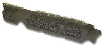

14 ACCESSORIES 14


15 ACCESSORIES Hand & Power Seamers available for rental or sale. 15
16 PRELIMINARY INSTALLATION GUIDE Please familiarize yourself with all installation instructions before starting work. Prior to panel installation, the installer should examine the decking or framing to ensure that all supporting members are straight, level and plumb to help prevent panel distortion. Substructures should be designed to meet all applicable code requirements. Panels must be installed straight, plumb and square to the eave. Some field cutting and fitting of panels and trims, as well as minor field corrections are a part of normal installation work. Follow the manufacturer s installation procedures, including fastener methods and creation of penetrations. Trim should be installed in proper alignment with the panels. The installer is responsible to insure a suitable decking prior to the application of StrongSeam SSFF1 panels. Panel distortions caused by handling, uneven decking, ripples or laps in the underlayment, construction debris or extreme temperature changes are not cause for rejection of material. Substructure Precautions Panel distortion may occur if applied over misaligned or non-uniform substructure. Check the roof deck for squareness before installing StrongSeam SSFF1 panels. Sealants must be field-applied according to manufacturer s instructions on dry, clean surfaces. All trims, closures and accessories shown on the installation drawings are available from Metal Panels Inc. unless otherwise noted. Oil-canning in the flat area of the panel is common to the industry and does not affect the integrity of the panel. Oil-canning is not a reason for rejection. 16
17 PRELIMINARY INSTALLATION GUIDE Two methods for verifying squareness of the structure for proper panel installation are shown below. Method 1: Measure diagonally across one slope of the roof from similar points at the ridge and eave and obtain the same dimension. Note that it is possible that a roof is out of square even with identical measurements. To verify, additionally measure the two longest sides. Method 2: A triangulation system may be used. Measure a point from the corner to the edge of the roof at a multiple of three (3). Measure another point from the same corner along the other edge at a multiple of four (4) Then, measure diagonally between the two points established; the dimension should be exactly a multiple of five (5) to have a square corner. Use this approach on more than one corner of a slope to verify building squareness. If the endwall cannot be made square, the roof system cannot be correctly installed. METHOD 1: 1X METHOD 2: 5X 1X 4X 3X 17
18 PRELIMINARY INSTALLATION GUIDE General Installation Overview Familiarize yourself with all installation instructions before starting work. Before beginning installation, you should examine the substrate or framing to ensure that all supporting members are straight, level, and plumb to avoid any panel distortion. Substructures should be designed and constructed to meet all necessary code requirements. Some field cutting and fitting of panels and trims is to be expected by the installer and minor field corrections are a part of normal installation work. It is the responsibility of the installer to ensure a suitable substrate prior to the application of a standing seam roof. Pan wave, commonly known as oil-canning in the panel can be caused by an uneven substrate, ripples, or laps in the vapor barrier, debris, protruding nails, staples or screws and are not defects in the material and are not the responsibility of Metal Panels Inc. The panels should be installed plumb, straight and square to the eave. To keep the bottom edge of the roof perfectly straight and even, the panels must be installed square to the bottom edge. Begin by checking the roof for square; if it is square, you may pull the layout marks directly from the edge of the rake. If the roof isn t perfectly square, install the first panel parallel to your square line, making sure that the Rake-J clip does not hang over the gable edge of the roof sheathing. Any overhang of the rake J-clip can prevent the rake trim from fitting tight against the rake. Note that care must be taken when aligning metallic panels; all metallic panels must run the same direction for a uniform appearance. See directional arrows on the underside of the panels and make certain that they all run the same direction. Oil-canning distortion in the flat area of the panels is common to the industry and does not affect the integrity of the panel. Therefore, oilcanning is not a reason for rejection. Optional striations reduce the frequency and severity of oil-canning. All trims, tools, and accessories shown on the installation drawings are available from Metal Panels Inc. unless otherwise noted. 18

19 PRELIMINARY INSTALLATION GUIDE Panel Installation 1. Panels should be installed perpendicular to the ridge for ridge trim attachment. Check panel alignment. 2. Attach Rake-J clip to roof with lowprofile pancake screws spaced at 30 on center. Female leg of the first panel rests inside J-clip. but not so snug that the flange deflects under the screw head. To allow for movement of the panel towards the eave or ridge, place the fastener in the middle of the 5/8 slot. Panel will be hooked over drip metal. 3. Align the female edge of the first panel with the chalk like that was snapped at the rake edges. This line can be 0 1 ¾ from the rake. 4. Fasten the panel along the male edge fastening flange with low-profile pancake head screws. Special care has to be taken not to overdrive the screws in the male edge fastening flange. The screw flange is slotted to allow for slight panel movement during normal expansion and contraction. To avoid panel distortion and to allow for maximum expansion and contraction of the panel, the screws should be snugged against the flange, DRIP METAL SSFF1 PANEL PANCAKE SCREW RAKE J CLIP POP-RIVET OR SCREW RAKE TRIM POP-RIVET OR SCREW PLACE SCREW IN CENTER OF SLOT TO ALLOW FOR PANEL EXPANSION FASTENER SPACING Maximum fastener spacing* for 16 wide 26 gauge panels with wind loads up to 80 mph. DECK THICKNESS SPACING 1/ O.C. 5/ O.C. 3/ O.C. *Slot on leg may not coincide with above chart. NOTE: UL90 is achieved by using a 5/8 thick exposure sheathing span C-D, 40/20 plywood and #10 x 1 long #2 phillips pancake head type A fasteners spaced 12 O.C. maximum with fasteners installed through prepunctured slots in fastener flange of panel. (UL Listed Construction Number 529) 19

20 PRELIMINARY INSTALLATION GUIDE 5. Align the second panel female edge with the starter panel male edge. Panels must be flush to one another. Remember, panels should hook onto drip edge. 6. Lightly compress and snap panels together at the seam. Snap panels from the eave to the ridge. Screw the second panel in place using low-profile pancake screws in the male edge fastening flange. Eave Termination without Fasteners (Recommended) Panels terminated with a hemming tool to provide a smoother appearance. Step 1: Create a tab in the panel by cutting a notch in both sides of the panel. Cut through the male and female ribs 1 up from panel end. See illustration below. 7. Continue to apply panels as in steps 5 and 6. Eave Termination Panels at the eave can be terminated in two ways; with hems (recommended) or with fasteners. Each will depend on the aesthetic consideration determined by the installer or building owner. TRIM PANELS BACK 1 AT MAJOR RIBS AS SHOWN Step 2: Place the hemming tool over the tab edge as shown below. PANEL BENDER BEND TAB TO FORM HEM Step 3: With the hemming tool bend the tab down and under to form a 180 o bend. 20
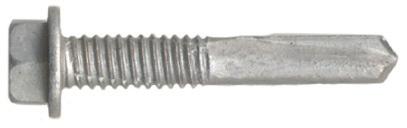
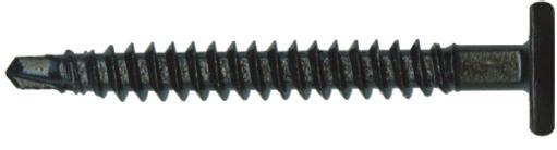
 Panels can be fastened along the eave with a #10 x 1 painted neoprene woodgrip fastener. Use butyl tape under the panel.")

21 PRELIMINARY INSTALLATION GUIDE Step 4: The panel is then ready to be installed over the drip edge trim, using the lip on the drip edge trim to secure the panel in place at the eave. OPEN PANEL HEM Eave Termination with Fasteners (Alternative) Panels can be fastened along the eave with a #10 x 1 painted neoprene woodgrip fastener. Use butyl tape under the panel. Fasten along a line parallel to the eave edge and 3 up from the eave edge. The fasteners can be spaced 4 apart in the minor rib striations, as shown below. When using the drip edge trim to terminate the eave, panels must be ordered approximately 2 longer than the ridge-to-eave length to account for the drip edge lip and the panel s hem. PANEL SCREWS BETWEEN STRIATIONS BUTYL TAPE UNDER PANEL 3 DRIP METAL 21


22 PRELIMINARY INSTALLATION GUIDE Trim Installation Overview On runs of more than 10 ft. that require more than one length of trim, overlap the pieces by 3 unless otherwise specified. When not affecting the water-tightness of overlaps, place overlaps such that the raw edges face away from the primary ground-level point of view. Trim is attached with rivets or washered screws; take care to drive the screws enough to compress the neoprene washer, but not enough to deflect the roofing or the trim. The critical part is finishing the ends of each trim run. It may take more time and attention, but cutting and folding the ends of the trim will give the roof a more finished look. Drip Edge 3. Using a hemming tool, fold the panel tab down and in, 180 o to form an open hem. PANEL BENDER 4. Slide panel over the drip edge, screw into decking, and snap in next panel. NOTCHED & TABBED BEND TAB TO FORM HEM 1. Screw the drip edge to the decking, 30 max. O.C. PANCAKE SCREWS, 30 O.C. DRIP METAL 5. Leave a tab when notching the rib, and use sealant in panel ends. Fold over the tab end of the rib for a more finished look. 2. Notch the SSFF1 panels by 1 at the ribs to create a tab of the panel width. FOLD OVER TAB END AND TRIM TRIM PANELS BACK 1 AT MAJOR RIBS AS SHOWN LEAVE TAB TO COVER PANEL ENDS 22


23 PRELIMINARY INSTALLATION GUIDE Rake Trim SSFF1 PANEL RAKE J CLIP POP-RIVET OR SCREW RAKE TRIM 3. For high wind areas, install the rake trim with pop-rivets 30 O.C. onto the rake J-clip, then using panel screws along the outside edge of the rake, 30 max. O.C. DRIP METAL PANCAKE SCREW POP-RIVET OR SCREW 4. Rake trim comes standard at 10 3, but can be run up to 21 ft. For longer runs, overlap the rakes by 3, using a bead of sealant between laps. 1. Install the continuous rake j-clip to the decking before installing panels using pancake screws, 30 max O.C. STRONGSEAM FASTENER FLANGE PANEL, NOTCHED AND HEMMED POP-RIVETS 30 O.C. RAKE TRIM STRONGSEAM FASTENER FLANGE PANEL, NOTCHED AND HEMMED RAKE J CLIP RAKE J CLIP POP RIVETS OR PANEL SCREWS, 30 O.C. 2. If roof requires a partial panel, measure width and add 1, then use a folding tool to bend a 90 o leg. 23

24 PRELIMINARY INSTALLATION GUIDE Sidewall Trim SSFF1 PANELS 1. Install roofing panels up to the sidewall. 2. Install sidewall trim onto the vertical wall, over top of sidewall felt or ice/water shield. Sidewall trim should overlap roofing rib completely. If roof requires a partial panel, measure width and add 1, then use a folding tool to bend a 90 o leg. 3. Screw trim to sidewall using low-profile pancake head woodgrips. Overlap the trims by 3 using a bead of sealant between laps PANCAKE HEAD WOODGRIP 30 O.C. SSFF1 PANELS SIDEWALL TRIM PANCAKE SCREWS, 30 O.C. STRONGSEAM FASTENER FLANGE PANEL SIDEWALL FLASHING 24

25 PRELIMINARY INSTALLATION GUIDE Endwall Trim (Roof-to-Wall) 1. Install roofing panels up to the endwall. Install Z-closure on top of the panel along the endwall, using butyl tape to ensure proper sealing. Z-closures are cut to width to fit between the major ribs. Trim ends of Z-closure to fit tightly to panel ribs. Use three low-profile pancake head wood grips to secure Z-closure to panel. Test-fit the endwall trim onto the Z-closure to locate position of Z-closures. Do not screw down the Z-closures until you are certain of their exact location. Use butyl tape on the underside of each Z-closure. Seal each vertical cut edge of Z-closures using a bead of sealant. Z-CLOSURE ENDWALL TRIM CAULK VERTICAL LEG OF Z-CLOSURE SSFF1 OR WALL PANEL NOTE: INSTALL ROOF PANEL & Z-CLOSURES FIRST. SLIDE ENDWALL TRIM ONTO Z-CLOSURES, THEN FASTEN TO END- WALL. SSFF1 PANEL LOW-PROFILE PANCAKE SCREW BUTYL TAPE 2. Slide the open hem of the endwall trim over the Z-closure and screw into the endwall. Pop-rivet the endwall trim to the Z-closures, between the panel ribs. Do not install the pop-rivets into the panel ribs. 3. For endwall trim runs longer than 10 ft., overlap the trims by 3, using a bead of sealant between the laps. ENDWALL TRIM STRONGSEAM FASTENER FLANGE PANEL PANCAKE SCREW, 30 O.C. POP-RIVET TO Z-CLOSURE Z-CLOSURE 25
 VALLEY CLEAT 2.")

26 PRELIMINARY INSTALLATION GUIDE Valley Installation BUTYL TAPE UNDER CLEATS 1. Using a folding tool, hem the eave bottom end of the valley 1 and slide over the drip edge, if used. If flush drip metal is used, fold valley hem down over drip metal and pop-rivet in place. SSFF1 PANEL VALLEY TRIM LOW-PROFILE PANCAKE SCREW (BUTYL TAPE UNDER CLEATS) VALLEY CLEAT 2. Install the valley to decking, placing low-profile pancake head screws up as far as possible on the high outsides of the valley, 30 max O.C. 3. Install valley cleats 4-5 up from the center valley rib using low-profile pancake screws and sealant. Seal the cleat to the valley using butyl tape or caulk. HEM PANELS TO ENGAGE CLEAT 4. Fabricate an open hem on each panel at the correct pitch for the valley. Slide the panel up to engage the cleat, snap in the panel at the rib, and screw male side of panel to decking. 5. Seal the panel ends and leave a tab when notching the rib. Fold the tab over the end of the rib for a more finished look. HEM VALLEY EAVE BOTTOM EDGE 26 VALLEY CLEAT PANCAKE SCREWS, 30 O.C.

27 PRELIMINARY INSTALLATION GUIDE Change Of Pitch Transition Trim 1. Install the lower roof panels per instructions and attach Z-closures. Trim ends of Z-closure to fit tightly to panel ribs. Use three low-profile pancake head wood grips to secure Z-closure to panel. Test-fit onto the Z-closure to locate position of Z-closures. Do not screw down the Z-closures until you are certain of their exact location. Use butyl tape on the underside of each Z-closure. Seal the cut vertical edges of the Z-closure with tube sealant. 2. Slide the open hem of the Change Of Pitch trim over the Z-closure and screw the trim to the upper decking using low-profile pancake head woodgrips. Pop-rivet trim to Z-closures. CHANGE OF PITCH TRIM, PANCAKE SCREWS, 30 O.C.; POP-RIVET TO Z-CLOSURES Z-CLOSURE CHANGE OF PITCH TRIM RIVET CAULK VERTICAL LEG OF Z-CLOSURE BUTYL TAPE UNDER CLEATS LOW-PROFILE PANCAKE HEAD SCREW BUTYL TAPE SSFF1 PANEL VALLEY CLEAT LOW-PROFILE PANCAKE SCREW SIDE ELEVATION 3. Install cleats 4-5 up from the center of Change Of Pitch trim using lowprofile pancake screws and sealant. Seal the cleat to the trim using butyl tape or caulk. Apply panels to upper roof overlapping COP transition by Fabricate an open hem on each panel at the correct pitch for the COP trim. Slide the panel up to engage the cleat, snap in the panel at the rib, and screw male side of panel to decking. 5. For longer runs, overlap trim by 6 and apply two beads of sealant between the laps. Z-CLOSURE BUTYL TAPE 27

28 PRELIMINARY INSTALLATION GUIDE Ridge Cap Trim 1. Install panels on both sides of roof up to the ridge, and install Z-closures. Trim ends of Z-closure to fit tightly to panel ribs. Use three low-profile pancake head wood grips to secure Z-closure to panel. Test-fit the endwall trim onto the Z-closure to locate position of Z-closures. Do not screw down the Z-closures until you are certain of their exact location. Use butyl tape on the underside of each Z-closure. Seal the vertical cut edges of the Z-closure with tube sealant. 2. Snap ridge cap over Z-closures and pop-rivet to the Z-closures between the panel ribs. PANCAKE WOOD GRIPS RIDGE CAP LOW-PROFILE PANCAKE SCREW CAULK VERTICAL LEG OF Z-CLOSURE Z-CLOSURE BUTYL TAPE SSFF1 PANEL 3. When overlapping ridge cap, a notched 6 overlap is required. MPI supplies Hip and Ridge factory-notched for a 6 lap. Pop-rivet with two beads of sealant between the laps. 4. Ridge caps can alternately be assembled using Ridge-J or Vented Ridge-J in place of the Z-closure. 12 RIDGE CAP BUTYL TAPE Z-CLOSURE 28

29 PRELIMINARY INSTALLATION GUIDE Vented Ridge Cap Trim 1. Install panels on both sides of roof up to the ridge, and install Z-closures. Trim ends of Z-closure to fit tightly to panel ribs. Use three low-profile pancake head wood grips to secure Z-closure to panel. Test-fit the endwall trim onto the Z-closure to locate position of Z-closures. Do not screw down the Z-closures until you are certain of their exact location. Use butyl tape on the underside of each Z-closure. Seal the vertical cut edges of the Z-closure with tube sealant. 2. Snap ridge cap over Z-closures and pop-rivet to the Z-closures between the panel ribs. RIDGE CAP LOW-PROFILE PANCAKE SCREW CAULK VERTICAL LEG OF Z-CLOSURE BUTYL TAPE SSFF1 PANEL VENTED Z-CLOSURE 3. When overlapping ridge cap, a notched 6 overlap is required. MPI supplies Hip and Ridge factory-notched for a 6 lap. Pop-rivet with two beads of sealant between the laps. 4. Ridge caps can alternately be assembled using Ridge-J or Vented Ridge-J in place of the Z-closure. RIDGE CAP FOR VENTED RIDGE PERFORATED Z-CLOSURE PANCAKE HEAD SCREWS BUTYL TAPE 29
30 Metal Panels Inc. 131 South 147th East Avenue Tulsa, Oklahoma (918) Voice (918) Fax Tulsa, Oklahoma Kansas City, Kansas Copyright 2016 Metal Panels Inc. All rights reserved. No part of this document may be reproduced or distributed without prior written authorization. 30
Central Snap. Condition Details C SNAPDETAILS
 Central Snap Condition Details D C SNAPDETAILS150612.2 The men and women at Central States Manufacturing, Inc. would like to welcome you. OUR MISSION Central States Manufacturing, Inc. is a 100% employee-owned
w w w. s a q u l i t y m e ta l s. c o m
 san antonio branch 210 W. Peden San Antonio TX 78204 P. (210) 227-7276 F. (210) 227-0329 MCALLEN branch 2221 Austin Ave McAllen TX 78501 P. (956) 627-2966 F. (956) 627-0918 w w w. s a q u l i t y m e ta
EVERSEAM 20 APPLICATION GUIDE
 EVERSEAM 20 APPLICATION GUIDE Panel Overview Our Name Says It All!"#$%#&'()*+,!"#$%#&'(-.( Applications: The EverSeam panel is an architectural panel that is ideal for residential and light commercial
Standing Seam Installation Guide
 Standing Seam Installation Guide Table of Contents Important Information... 3 Handling Material... 3 Delivering Material... 4 Mechanical Unloading... 4 Design Considerations... 4 Fastener Selection...
RESIDENTIAL LIGHT GAUGE APPLICATION GUIDE
 Our Name Says It All RESIDENTIAL LIGHT GAUGE APPLICATION GUIDE Lebanon, PA 888.339.0059 Bridgton, ME 800.677.2060 Howe, IN 866.562.3782 www.everlastroofing.com Residential Light Gauge Table of Contents
IMPORTANT NOTICE READ THIS MANUAL COMPLETELY PRIOR TO BEGINNING THE INSTALLATION OF THE WEATHER GUARD PANEL.
 IMPORTANT NOTICE READ THIS MANUAL COMPLETELY PRIOR TO BEGINNING THE INSTALLATION OF THE WEATHER GUARD PANEL. IF THERE IS A CONFLICT BETWEEN PROJECT ERECTION DRAWINGS PROVIDED OR APPROVED BY WHIRLWIND BUILDING
ABSeam Panel Overview and Installation Instructions
 82 Garden Spot Road Ephrata, PA 17522 717-445-6885 35 Ridge Road Newville, PA 17241 717-776-5951 ABSeam Panel Overview and Installation Instructions Applications: The ABSeam panel is an architectural panel
* Other widths available upon request. 24 Gauge Galvalume - Standard Surface. Other gauges and aluminium available upon request.
 is a concealed fastener architectural standing seam roof panel. The panels are easily installed over decking, utilizing metal clips. panels are ideally suited for decorative mansard, fascia and roofs.
Installation Guide MATTERHORN METAL ROOFING TO LAST A LIFETIME. MATTERHORN Tile
 Installation Guide MATTERHORN METAL ROOFING TO LAST A LIFETIME MATTERHORN Tile Watch detailed installation videos online at matterhornmetalroofing.com/tile-installation Table of Contents Accessories: Most
w w w. s a q u l i t y m e ta l s. c o m
 san antonio branch 210 W. Peden San Antonio TX 78204 P. (210) 227-7276 F. (210) 227-0329 MCALLEN branch 2221 Austin Ave McAllen TX 78501 P. (956) 627-2966 F. (956) 627-0918 w w w. s a q u l i t y m e ta
Prior to ordering and installing materials, all dimensions should be verified by field measurements.
 Important Information The application and detail drawings in this manual are strictly for illustration purposes and may not be applicable to all building designs or product installations. All projects
Black s Metals Installation Guide
 Storage Black s Metals Installation Guide If metal is not to be used immediately, store inside in a well ventilated, dry location. Condensation or other moisture can form between the sheets during storage
Table of Contents. Notes to Designer/User Map of Typical Roof Conditions...3 Fastener Placement...4 Fastener Selection...5
 Table of Contents Section Page Notes to Designer/User...................1-2 Map of Typical Roof Conditions..............3 Fastener Placement........................4 Fastener Selection.........................5
TYPICAL ROOF CONDITION LAYOUT
 FIXED POINTS TYPICAL ROOF CONDITION LAYOUT 15 17 9 16 29 12 14 11 3 7 35 20 6 23 30 31 24 13 18 Typical Roof Condition Layout... 1 Low Eave Isometric View - Fixed/ Floating... 2 Low Eave Section - Fixed/
Roofing Installation Manual: Concealed Fastener Panels Material Data, Trim Details, and Step-by-Step Instructions
 Roofing Installation Manual: Concealed Fastener Panels Material Data, Trim Details, and Step-by-Step Instructions 1974 Livengood Ave Fairbanks, AK 99701 907-479-6002 allsteel.info@gmail.com Roof Installation
2120 SW Poma Drive; Palm City, Florida Phone Fax
 2120 SW Poma Drive; Palm City, Florida 34990 772-223-4055 Phone 772-781-7492 Fax www.sunlastmetal.com sales@sunlastmetal.com IMPORTANT NOTICE READ THIS MANUAL COMPLETELY BEFORE BEGINNING INSTALLATION OF
FABRAL The pursuit of excellence since 1967
 1 1/2" SSR Detail Manual and Estimate Guide 16" 1 1 2 " PROPER STORAGE When moisture remains in contact with Galvanized panels in the absence of freely circulating air, white, black, or gray corrosion
1 1/2" SSR. FABRAL The pursuit of excellence since 1967
 1 1/2" SSR Detail Manual and Estimate Guide 16" 1 1 2" PROPER STORAGE When moisture remains in contact with Galvanized panels in the absence of freely circulating air, white, black or dark gray corrosion
SECTION METAL ROOF AND SOFFIT PANELS
 Metal Panel Systems, Inc. 11506 Reading Road Cincinnati, Ohio 45241-2512 Telephone: 800-554-6126 or 513-554-6120 Fax: 513-554-6121 www.metalpanelsystems.com info@metalpanelsystems.com Specifications for
ML-150. w w w. s a q u l i t y m e ta l s. c o m. san antonio branch 210 W. Peden San Antonio TX P. (210) F.
 F.") ML-150 san antonio branch 210 W. Peden San Antonio TX 78204 P. (210) 227-7276 F. (210) 227-0329 MCALLEN branch 2221 Austin Ave McAllen TX 78501 P. (956) 627-2966 F. (956) 627-0918 w w w. s a q u l i t
ML-150 san antonio branch 210 W. Peden San Antonio TX 78204 P. (210) 227-7276 F. (210) 227-0329 MCALLEN branch 2221 Austin Ave McAllen TX 78501 P. (956) 627-2966 F. (956) 627-0918 w w w. s a q u l i t
DL-200. Specifications
 DL-200 Specifications Everlast Metals 10 Enterprise Court Lebanon, PA 17042 Phone: (717) 270-6554 Fax: (717) 270-6569 www.everlastmetals.com 7410 Structural Preformed Metal Roofing PART 1: GENERAL 1.01
2120 SW Poma Drive; Palm City, Florida Phone Fax
 2120 SW Poma Drive; Palm City, Florida 34990 772-223-4055 Phone 772-781-7492 Fax www.sunlastmetal.com sales@sunlastmetal.com IMPORTANT NOTICE READ THIS MANUAL COMPLETELY BEFORE BEGINNING INSTALLATION OF
TRIAD CORRUGATED METAL, INC.
 TRIAD CORRUGATED METAL, INC. C O M M E R C I A L R E S I D E N T I A L A G R I C U L T U R A L Snap Loc Panel Guide Snap Loc metal panels are a perfect fit for residential, architectural and commercial
1.5 mechanical lock ml 150
 1.5 mechanical lock ml 150 Strip Width Base Material Thickness Min Tensible Min Yield Coatings Max 16 Steel.0225 to.0336 in 52 - ksi 50 - ski Painted / Galvalume UL CONSTRUCTION NUMBERS: TGKX554 The Mechanical
SSL-175. Specifications
 SSL-175 Specifications Everlast Metals 10 Enterprise Court Lebanon, PA 17042 Phone: (717) 270-6554 Fax: (717) 270-6569 www.everlastmetals.com 7410 Preformed Metal Roofing PART 1: GENERAL 1.01 SECTION INCLUDES
Recla Metals RCM INSTALLATION GUIDELINES
 Recla Metals RCM INSTALLATION GUIDELINES Caution: RCM roofing panels must be applied on a minimum roof pitch of 2½:12 or greater. Important Notice: This guide must by read in its entirety before beginning
Western States 7/8 Corrugated
 Western States 7/8 Corrugated Installation, Flashings & Shop Drawing Detail Guide Table of Contents Section Page Section Page Notes to Designer / Installers..1 Fastener Placement and Selection.2-3 Key
WESTERN RIB. Installation, Flashings & Shop Drawing Detail Guide.
 WESTERN RIB Installation, Flashings & Shop Drawing Detail Guide 901 W. Watkins Street Phoenix, AZ 85007 Phone: (877) 787-5467 (855) 426-7836 Email: sales@cortenroofing.com sales@metalforroofing.com For
Guide Specifications ADP Series SECTION SHEET METAL ROOFING
 PART 1 GENERAL 1.01 SUMMARY A. Section Includes: Sheet metal roofing panels, metal trim, accessories, fasteners, closures, and sealants. [Specifier Note: Edit paragraph below to suit project requirements.]
INSTALLATION GUIDE.
 INSTALLATION GUIDE www.gerardusa.com INSTALLATION NOTIFICATION The installation procedures demonstrated in this manual are recommended methods for the installation of the Gerard Canyon Shake counter batten
4572 N Old US 31, Rochester, IN Toll Free: Fax: Installation Guide SUPER-LOC 16 STANDING SEAM
 4572 N Old US 31, Rochester, IN 46975 Installation Guide SUPER-LOC 16 STANDING SEAM IMPORTANT INFORMATION This manual contains suggestions and guidelines on how to install Super-Loc 16 Standing Seam panels.
1.5 mechanical lock ml 150
 1.5 mechanical lock ml 150 Strip Width Base Material Thickness Min Tensible Min Yield Coatings Max 16 Steel.0225 to.0336 in 52 - ksi 50 - ski Painted / Galvalume UL CONSTRUCTION NUMBERS: TGKX554 The Mechanical
R PANEL / PBR PANEL. Installation, Flashings & Shop Drawing Detail Guide.
 R PANEL / PBR PANEL Installation, Flashings & Shop Drawing Detail Guide 901 W. Watkins Street Phoenix, AZ 85007 Phone: (877) 787-5467 (855) 426-7836 Email: sales@cortenroofing.com sales@metalforroofing.com
4572 N Old US 31, Rochester, IN Toll Free: Fax: Installation Guide SUPER-LOC 16 STANDING SEAM
 Installation Guide SUPER-LOC 16 STANDING SEAM IMPORTANT INFORMATION This manual contains suggestions and guidelines on how to install Super-Loc 16 Standing Seam panels. The drawings in this guide are for
Classic Rib Roofing Panels DETAIL MANUAL
 Metal Roofing Wholesalers Classic Rib Roofing Panels DETAIL MANUAL www.metalroofingwholesalers.com 1170 Topside Rd Louisville, TN 37777 The Classic Rib Roofing Panel Figure 1 House With Classic Rib Metal
SOUNDGUARD INSTALLATION MANUAL
 SOUNDGUARD INSTALLATION MANUAL WWW.ROOFSCREEN.COM 831 421 9230 Introduction... 2 This manual... 2 Application... 2 System Overview... 2 Components... 2 Face Panels... 3 Insulation... 3 Perforated Liner
ALLMET CONTINENTAL INSTALLATION GUIDE
 ALLMET CONTINENTAL INSTALLATION GUIDE www.allmet.com INSTALLATION NOTIFICATION The installation procedures demonstrated in this manual are recommended methods for the installation of the Allmet Continental
PROLOK EAVE PROLOK ROOFING PANEL ROOFING NAIL
 EAVE ROOFING NOTE: ROOF PITCH IS REQUIRED FOR FABRICATION LOW SLOPE ADD SEALER TAPE ROOFING NAIL 2x4 SUB- 2x8 EAVE TRIM 1. Install the eave trim using roofing nails. 2. If sealer tape is being used, install
Flat. Ribbed Striated and 1 ½ TCM-Lok Installation Manual
 Flat Ribbed.748.941.472 15.75 1.248 Striated.748.472 14.75 1.5.248.941 www.tricountymetals.com 1 and 1 ½ TCM-Lok Installation Manual Table of Contents Important Notice/Safety/Storage/Tools...1 Roofing
ROOF OWNER'S OPERATION AND MAINTENANCE MANUAL
 ROOF OWNER'S OPERATION AND MAINTENANCE MANUAL Table of Contents Section Title Page Section 1.0 General Maintenance Statement 2 Section 2.0 Safety 2 Section 3.0 Inspections 2-4 Section 4.0 Repairs 4 Section
Pacific Tile Counter Batten and Batten
 Pacific Tile Counter Batten and Batten INSTALLATION GUIDE www.gerardusa.com INSTALLATION NOTIFICATION The installation procedures demonstrated in this manual are recommended methods for the installation
Pacific Tile Counter Batten and Batten
 Pacific Tile Counter Batten and Batten INSTALLATION GUIDE www.gerardusa.com Page2 INSTALLATION NOTIFICATION The installation procedures demonstrated in this manual are recommended methods for the installation
Classic and NB Tile Counter Batten and Batten
 Classic and NB Tile Counter Batten and Batten INSTALLATION GUIDE www.gerardusa.com INSTALLATION NOTIFICATION The installation procedures demonstrated in this manual are recommended methods for the installation
FF100 SNAPLOCK INSTALLATION MANUAL
 FF100 SNAPLOCK INSTALLATION MANUAL TABLE OF CONTENTS INTRODUCTION P. 3 OWNER INFORMATION P.4 SAFETY P.5 OIL CANNING P.6 THERMAL MOVEMENT P.7 CONDENSATION AND VENTILATION P.8 INSTALLATION INSTRUCTIONS P.9-11
Installing the Sno-free Panel Eave System for New Roofs
 Installing the Sno-free Panel Eave System for New Roofs SFP CLEAT SFP BASE SFP EXTRUSION SFP TOP COVER Step # 1 Placing the Cleat Install Ice and Water Shield as per code to the edge of sheeting. Install
3' COMMERCIAL RIB PREFORMED METAL SIDING
 SECTION 07410 3' COMMERCIAL RIB PREFORMED METAL SIDING PART 1 GENERAL 1.01 DESCRIPTION A. Work in this section includes furnishing and installation, preformed steel ribbed siding on vertical portions of
Product Guide HELPFUL INFORMATION ON PANELS, TRIMS, GUTTERS AND ACCESSORIES
 5V Product Guide HELPFUL INFORMATION ON PANELS, TRIMS, GUTTERS AND ACCESSORIES ½" 24" COVERAGE Copyright 2018, Central States Manufacturing, Inc., All Rights Reserved. D C GUID_PROD_5V_180201 The men
Architectural Wall Products Guide Specifications
 Western States Metal Roofing 901 W. Watkins St. Phoenix, AZ 85007 PH: 602-495-0048 FX: 602-261-7726 Architectural Wall Products Guide Specifications FORMED METAL WALL PANELS This Guide Specification is
SNAP-LOK 1 1/2 Installation Manual
 Flat Ribbed.709.394.197 15.5.248 1.417 1.496 Striated www.tricountymetals.com SNAP-LOK 1 1/2 Installation Manual Table of Contents Important Notice/Safety/Storage/Tools...1 Roofing Anatomy/Side Trim...2
BARREL VAULT Tile Counter Batten and Batten Installation Guide
 BARREL VAULT Tile Counter Batten and Batten Installation Guide www.boral.com Page2 BARREL VAULT Tile Actual Size= 43 13/16 x 15 5/8 Exposure= 43 1/4 x 14 Weight= 5.4lbs. per panel Panels per square (100
ENERGY STAR PARTNER. PBR & R Panel
 ENERGY STAR PARTNER 1 Table of Contents Important Information Installation Information Technical Information Trims and Flashings Illustration Roo ng Installation Details Eave Flashing (EF-3) Eave Flashing
5V Crimp DESIGN/INSTALLATION INFORMATION
 5V Crimp DESIGN/INSTALLATION INFORMATION IMPORTANT NOTICE READ THIS MANUAL COMPLETELY PRIOR TO BEGINNING THE INSTALLATION OF THE SYSTEM. METAL DEPOTS DETAILS MUST BE FOLLOWED AS A MINIMUM TO INSURE APPROPRIATE
Architectural Roof Products Guide Specifications
 Western States Metal Roofing 901 W. Watkins St. Phoenix, AZ 85007 PH: 602-495-0048 FX: 602-261-7726 Architectural Roof Products Guide Specifications FORMED METAL ROOF AND WALL PANELS This Guide Specification
CONTOUR CORRUGATED PANEL
 CONTOUR CORRUGATED PANEL Table of Contents SECTION PAGE Designer Notes............................................... 1 Panel Net Coverage / Fasteners.................................... 2 ROOF Details
Architectural Roof Products Guide Specifications
 Western States Metal Roofing 901 W. Watkins St. Phoenix, AZ 85007 PH: 602-495-0048 FX: 602-261-7726 Architectural Roof Products Guide Specifications FORMED METAL ROOF AND WALL PANELS This Guide Specification
KBS-100 SNAP-LOCK PANEL & 5V PANEL I N S T A L L A T I O N M A N U A L
 KBS-100 SNAP-LOCK PANEL & 5V PANEL I N S T A L L A T I O N M A N U A L KBS Metal Roofing KBS Metal Roofing General Information General Information Before beginning installation of panels, the installer
4572 N Old US 31, Rochester, IN Toll Free: Fax: DETAIL MANUAL. and guide to Ramco Supply products
 DETAIL MANUAL and guide to Ramco Supply products Metal Roofing and Siding Panels & Accessories 1 Ramco Supply s RAM Roofing Panels Ramco Supply s RAM panels are a strong, durable, economic, and attractive
Standing Seam Roof Systems General Information Guide
 This guide can be used in conjunction with the McElroy Metal Installation Manuals to help plan and organize the installation of the McElroy Metal standing seam roof systems. The Installation Manuals will
a division of NCI Standing Seam Roof Systems
 a division of NCI Standing Seam Roof Systems Building Benefits You Can Expect From A&S Materials Standing Seam roof panels weigh a relatively modest 11/2 pounds per square foot. When long life is required
SECTION PREFORMED CLADDING. A. Part A and DIVISION 1 of PART B are hereby made a part of this SECTION.
 SECTION 074213 PART 1 GENERAL 1.01 GENERAL REQUIREMENTS A. Part A and DIVISION 1 of PART B are hereby made a part of this SECTION. B. Examine all conditions as they exist at the project prior to submitting
Brava Spanish Tile. Installation Manual. Brava Roof Tile Phone: Fax:
 Brava Spanish Tile Installation Manual Brava Roof Tile Phone: 319-338-5706 Fax: 319-343-1038 www.bravarooftile.com This document includes the recommended and suggested installation procedures for Brava
JUNIOR HF Steel Roof Panels
 Contents Page Introduction, Storage.. 2 Preparation..... 3 Tools and Equipment, Important Notice..... 4 Installation Details Overview. 5 Gable End Details.. 6 Eave Details. 7 Ridge Details.. 8 Hip Details......
Architectural Roof and Wall Products Guide Specifications
 Architectural Roof and Wall Products Guide Specifications 901 W. Watkins St. Phoenix, AZ 85007 PH: 602-495-0048 FX: 602-261-7726 FORMED METAL ROOF AND WALL PANELS This Guide Specification is to be used
INSTALLATION MANUAL Heritage Series
 INSTALLATION MANUAL Heritage Series STEEL ROOF PANELS HEAD OFFICE 1418 Michael St., Ottawa, ON K1B 3R2 WATS LINE: 1 800-267-0860 TEL.: 1 613-746-3206 FAX: 1 613-746-0445 Contents Page Introduction, Storage..
SL150 Guide Specification
 SL150 Guide Specification This is a suggested guide specification for metal roofing projects where the SL150 panel system is applicable. Questions regarding applicability should be discussed with Union
OSU PROJECT NO PAGE 1 02 NOV 2006 SECTION METAL ROOF PANELS
 OSU PROJECT NO. 30-04-15 PAGE 1 PART 1 GENERAL 1.1 SECTION INCLUDES A. Structural roofing system of preformed steel panels. B. Fastening system. C. Factory finishing. D. Accessories and miscellaneous components.
ML150 Guide Specification
 ML150 Guide Specification This specification is a guide recommendation for many metal roofing projects. It is available for downloading in both Microsoft WORD and.pdf format for your ease of use. Revise
Advantage-Lok II. Standing Seam Roof System. Product Guide
 Advantage-Lok II Standing Seam Roof System Product Guide January 2018 Table of Contents 1. General Information. 4 a. Notice b. Applicability c. Safety d. Material Handling and Storage e. Packaging f. Unloading
Architectural Roof and Wall Products Guide Specifications
 Architectural Roof and Wall Products Guide Specifications Western States Metal Roofing 901 W. Watkins St. Phoenix, AZ 85007 PH: 602-495-0048 FX: 602-261-7726 FORMED METAL WALL PANELS This Guide Specification
TRIAD CORRUGATED METAL, INC.
 TRIAD CORRUGATED METAL, INC. COMMERCIAL RESIDENTIAL AGRICULTURAL MS-216 MS-218 Panel Guide This guide describes the design and performance characteristics of the MS-216 and MS-218 Roof panel system. The
1 1/2" SSR. FABRAL The pursuit of excellence since 1967
 1 1/2" SSR Detail Manual and Estimate Guide 16" 1 1 2" PROPER STORAGE When moisture remains in contact with Galvanized panels in the absence of freely circulating air, white, black or dark gray corrosion
238T Aluminum Standing Seam Metal Roof System (SSMRS)
") 238T Aluminum Standing Seam Metal Roof System (SSMRS) Text in red are instructions to the specifier and should be deleted. Text in blue are choices that need to be made, with those not selected, deleted.
238T Aluminum Standing Seam Metal Roof System (SSMRS) Text in red are instructions to the specifier and should be deleted. Text in blue are choices that need to be made, with those not selected, deleted.
Stile. Spanish Tile Installation Guide
 Stile Spanish Tile Installation Guide IMPORTANT INFORMATION THE APPLICATION AND DETAIL DRAWINGS IN THIS MANUAL ARE STRICTLY FOR ILLUSTRATION PURPOSES AND MAY NOT BE APPLICABLE TO ALL BUILDING DESIGNS OR
CS-100 Guide Specifications
 MANUFACTURER CUSTOM-BILT METALS 1333 Corporate Drive, Suite 103 Irving, Texas 75038-2520 (800) 826-7813 or info@custombiltmetals.com www.custombiltmetals.com CS-100 Guide Specifications This Guide Specification
SECTION BATTEN SEAM COPPER ROOFING
 PART 1 - GENERAL 1.1 DESCRIPTION: SECTION 07 61 16 BATTEN SEAM COPPER ROOFING SPEC WRITER NOTES: 1. Delete between // // if not applicable to project. Also delete any other item or paragraph as required
SECTION PRE-ENGINEERED BUILDING INSULATION
 PART 1 GENERAL SECTION 07213 PRE-ENGINEERED BUILDING INSULATION Microsoft Word Instructions: Display hidden notes to specifier by using "Tools"/"Options"/"View"/"Hidden Text". 1.1 SECTION INCLUDES A. Pre-Engineered
Eclipse OSB Radiant Barrier OSB Structural Panels from RoyOMartin
 Product Information & Installation Instructions Eclipse OSB Radiant Barrier OSB Structural Panels from RoyOMartin Installation Instructions: Site-Built and Modular Construction Important notice to buyers
ReflectiClean Acrylic/Urethane
 1 DG0009-J 08/2015 Metal Roof Restoration Sample Design Guidelines ReflectiClean Acrylic/Urethane ITW POLYMERS SEALANTS NORTH AMERICA, INC. 111 S. Nursery Road. Irving, TX 75060 Tel: 972-438-9111 Fax:
SECTION METAL ROOF PANELS
 SECTION 07 41 13 PART 1 GENERAL 1.1 SECTION INCLUDES A. Standing-seam roof panels. B. Metal roofing accessories. 1.2 RELATED SECTIONS A. Section 07 62 00 - Sheet Metal Flashing. B. Section 07 72 00 - Roof
SECTION PRE-ENGINEERED METAL BUILDING
 SECTION 13121 PRE-ENGINEERED METAL BUILDING PART 1 GENERAL 1.01 SCOPE OF WORK A. Furnish all labor, materials, equipment and incidentals required to design, fabricate, deliver to project site, and erect
SHURLOC 150 STANDARD DETAILS
 OVER WOOD DECK STANDARD DETAILS Austin - Headquarters/Sales Office 830 Sagebrush Drive Austin, TX 78758 (512) 452-1515 (800) 428-7412 Fax (512) 833-7499 www.ctmrs.com email: info@ctmrs.com Seguin - Plant/Sales
NRM-7000 Guide Specifications
 NRM-7000 Guide Specifications MANUFACTURER www.nuraymetals.com sales@nuraymetals.com 800-700-7228 SECTION 07 411 PREFORMED ROOF & WALL PANELS PART 1 - GENERAL 1.1 SUMMARY A. Section includes complete system
ATAS International, Inc. BUILDING PANEL TRANSIT, JOB SITE HANDLING AND STORAGE PROCEDURES
 ATAS International, Inc. BUILDING PANEL TRANSIT, JOB SITE HANDLING AND STORAGE PROCEDURES 800.468.1441 www.atas.com info@atas.com Contents Objectives Transit Receiving Forklift unloading and handling Crane
For Metal Roofing Systems Fascia, Mansards,& Soffits
 HIGGINS STEEL ROOFING SERIES 2000 STANDING SEAM DETAIL MANUAL For Metal Roofing Systems Fascia, Mansards,& Soffits Wall Panels/Siding HIGGINS CONSTRUCTION & SUPPLY CO. 3801 U. S. 50 HILLSBORO, OHIO 45133
Agenda. Safety Decking Basics Decking Issues Felt Kick Out Flashing Fascia
 Decking & Fascia Agenda Safety Decking Basics Decking Issues Felt Kick Out Flashing Fascia 2 Chapter 7 Tools & Materials Tools for Decking Hammer Measuring Tape Chalk Line Speed Square Utility Knife Circular
Table of Contents. 3. Standing Seam Panels
 Table of Contents 895 North Parkway 3. Standing Seam Panels Standing Seam Panels Table of Contents... PS1-2 Double-Lok... PS3-8 Ultra-Dek... PS9-14 BattenLok HS... PS15-18 Curved BattenLok HS... PS19-20
SL-16. Design/Installation Information
 SL-16 Design/Installation Information IMPORTANT NOTICE READ THIS MANUAL COMPLETELY PRIOR TO BEGINNING THE INSTALLATION OF THE SL Series ROOFING SYSTEM. ALWAYS INSPECT EACH AND EVERY PANEL AND ALL ACCESSORIES
Battenless. Installation Guide BATTENLESS INSTALLATION GUIDE 1
 Battenless Installation Guide BATTENLESS INSTALLATION GUIDE 1 This manual provides general guidelines and procedures relating to the estimating and installation of Varitile roof products. It is not a training
SECTION EXTERIOR GRILLS AND SCREENS
 SECTION 10 82 13 PART 1 GENERAL PART 1 1 SUMMARY A. Section Includes: 1. Exterior perforated aluminum screen wall system with Ombrae TM Optical Tile imaging technology. 2. Accessories including attachments,
1.5 snap lock sl 150
 1.5 snap lock sl 150 Strip Width Base Material Thickness Min Tensible Min Yield Coatings 12.00 to 24 Steel.0128 to.027 in 52 - ksi 50 - ski Painted / Galvalume UL CONSTRUCTION NUMBERS: TGKX301, tgkx342a,
INSTALLATION MANUAL. METAL INSULATED PANELS -ROXUL -Expanded Polystyrene
 INSTALLATION MANUAL METAL INSULATED PANELS -ROXUL -Expanded Polystyrene Insulated Metal Panels London Eco-Metal Manufacturing Inc. **Also see Eco-Metal s Handling Manual** These instructions are provided
Acrylic/Urethane. Metal Roof Restoration Sample Design Guideline
 1 DG0009-I 04/2017 Metal Roof Restoration Sample Design Guideline Acrylic/Urethane ITW POLYMERS SEALANTS NORTH AMERICA, INC. 111 S. Nursery Road. Irving, TX 75060 Tel: 972-438-9111 Fax: 972-554-3939 www.itwsealants.com
Resysta Wall Cladding Installation Guidelines
 Resysta Wall Cladding Installation Guidelines NOTE: Proper planning of the wall cladding layout is essential for ease of installation of wall cladding boards and wall cladding components. Thoroughly read
Versa-Span Flashings and Details Guide
 Flashings and Details Guide STRUCTURAL SNAP-LOCK Features & Benefits 14-5/8" and 18" Standard Panel Width 1-3/4" Snap Lock Seam Custom Lengths 2'0" to 300'0" Concealed Clip System - No Seaming Required
ROOFING EPDM ELASTOMERIC SHEET ROOFING FULLY ADHERED- CONVENTIONAL
 ROOFING EPDM ELASTOMERIC SHEET ROOFING FULLY ADHERED- CONVENTIONAL PART 1 GENERAL 1.1 SECTION INCLUDES A. Insulation, membrane roofing, base flashings roofing membrane accessories joints, and counter flashings.
SRP-AirOutshield ROOF Issued:
 SECTION 07276: Breathable Underlayment Guide Specification This specification is a guide only and may need editing for the specific intended application. It is the responsibility of the design professional
SECTION METAL ROOFING MASTER SPECIFICATION
 SECTION 07 41 13 METAL ROOFING MASTER SPECIFICATION PART I - GENERAL REQUIREMENTS 1.01 DESCRIPTION OF WORK: A. Section Includes: The extent of each type of preformed metal roofing panel as indicated on
Chapter 7. Roof Framing
 Chapter 7. Roof Framing 7.1 ROOFING PREP WORK 7.2 INSTALLING ROOF TRUSSES 7.3 INSTALLING PORCH TRUSSES 7.4 SHEATHING ROOF 7.5 INSTALLING SUB-FASCIA 7.6 BUILDING AND INSTALLING SCUTTLE BOX 7.7 INSTALLING
Installation Guide. Mission Tile. Distributed by: BEST MATERIALS LLC, Phoenx AZ
 RPM ROOFING Installation Guide Mission Tile Distributed by: BEST MATERIALS LLC, Phoenx AZ 602-272-8128 800-474-7570 www.bestmaterials.com Table of Contents OVERVIEW...1 CAUTION...1 DISCLAIMER...1 PRODUCT
SECTION SELF-ADHERED WATER-RESISTIVE ROOF UNDERLAYMENT
 SECTION 07 30 05.01 SELF-ADHERED WATER-RESISTIVE ROOF UNDERLAYMENT SPEC WRITERS NOTE: This specification includes materials and installation procedures for SlopeShield SA Self-Adhered Water-Resistive Vapor