R e t a i n i n g W a l l s. Segmental Retaining Walls. Installation Guide
|
|
|
- Mervin Scott
- 6 years ago
- Views:
Transcription


1 R e t a i n i n g W a l l s Segmental Retaining Walls Installation Guide
2 R e t a i n i n g W a l l s EverLoc Retaining Walls P O Box Swords Creek Road Swords Creek, VA Everloc Installation Guide - 2nd Edition Text and Drawings by: Billy J. Wauhop, PE Inventor of EverLoc Copyright 2013 EverLoc Retaining Walls Helpline: (877) Ph: / Fax:
3 11 INSTALLATION RULES and GUIDELINES Introduction Page 3 Gravity walls Page 4 Soil-reinforced walls Page 6 Retaining wall components Page 8 Excavation Page 8 Foundation soil Page 8 Leveling pad Page 9 EverLoc SRW units Page 11 Drainage pipe Page 12 Drainage aggregate Page 14 Infill soil Page 16 Retained soil Page 16 Soil reinforcement Page 16 Installing successive courses Page 20 Capping and finish grading Page 21 Fence Walls Page 22 Parapet Walls Page 26 Column Insets Page 30 Free Standing Columns Page 32 Radius Walls Page 35 No Saw Corners Page 37
4 22 DETAIL DRAWINGS AND ESTIMATING CHARTS Drawing 101 Gravity walls Page 40 Drawing T retaining walls Page 41 Drawing T tiered walls Page 42 Drawing 104 Shoreline protection Page 43 Drawing 105 Outside radius Page 44 Drawing 106 Inside radius Page 45 Drawing 107 Outside corner Page 46 Drawing 108 Outside corner reinforced Page 47 Drawing 109 Inside corner Page 48 Drawing 110 Inside corner reinforced Page 49 Drawing 111 Base step Page 50 Drawing T Parapet/Fence wall Page 51 Drawing 113 Stair detail Page 52 Drawing 114 Stair detail elevation view Page 53 Drawing 115 Column detail Page 54 Drawing 116 In-Line Column detail Page 55 AZTEC installation patterns Page 56 Estimating chart No. 1 Static conditions Page 57 Estimating chart No. 2 Seismic conditions Page 58 References Page 59
5 33 INTRODUCTION This document is provided as a guide to contractors and owners specifically for the installation of EverLoc Segmental Retaining Wall Systems. It addresses the specific installation steps for engineered and non-engineered EverLoc systems. These are the general installation methods for EverLoc. Contractors should also reference the product specific information provided by the geogrid and geotextile manufacturers. The EverLoc system is a gravity retaining wall system that relies primarily on its mass (weight) for stability. The system consists of concrete masonry units which are placed without the use of mortar (dry stacked). The system then relies on the proven combination of a mechanical interlock and mass to prevent both sliding at the base of the wall and overturning about the toe of the structure. The units may also be used in combination with horizontal layers of soil reinforcement (geogrid). The geogrid extends into the earthen backfill to increase the effective width and weight of the gravity mass. The use of geogrid allows EverLoc walls to be built to virtually any height. The EverLoc system is considered a flexible structure, so the base course does not need to be placed below the frost line provided there is sufficient foundation bearing capacity to support the wall. TIP Check local building codes to determine if the project needs engineering or not. If so, follow design drawings EXACTLY. Get approval from the wall designer before making any changes.
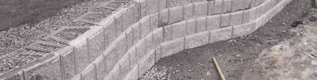
6 44 GRAVITY WALLS EverLoc gravity walls are constructed with either single (typical) or multiple depths of units. For stability, the EverLoc gravity structure must have sufficient mass to prevent both sliding at the base and overturning about the toe of the structure. Since the system consists of individual units, dry stacked one atop another, shear capacity is an important component to assure that the units act together as a coherent mass. Shear capacity provides a means of transferring lateral forces from each course to the succeeding course. This is provided: 1) by the frictional resistance between the EverLoc units, 2) by the interlock action provided by lugs and grooves which are an integral part of the units, and 3) by the compacted columns of aggregate placed in the open cores of the EverLoc units. The batter (or inclination) of the wall contributes to the stability of the finished wall. This batter is achieved through the setback between EverLoc units from one course to the next. The batter is controlled by the location of lugs and grooves on each unit. Gravity walls should not be erected over four (4) feet in height (or as governed by state or local building codes) without first having been designed by a qualified licensed engineer. See Drawing 101 as an example of an EverLoc gravity retaining wall: TIP Gravity wall heights may be reduced if steep top slopes, poor foundation soils, or ground water is encountered. Consult a design professional if any of these conditions are present.


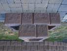
7 Example of a Gravity Wall 5
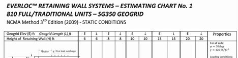
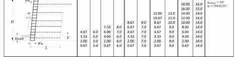
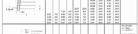
8 66 SOIL-REINFORCED WALLS Soil-reinforced walls should be specified 1) when the maximum height (typically four feet) for conventional gravity walls is exceeded or 2) when lower walls are surcharged by sloping backfills, live loads and/or have poor foundations. A soil-reinforced EverLoc wall is designed and constructed with multiple layers of soil reinforcement placed between the EverLoc courses and extending back into the soil behind the wall at designated elevations and lengths. The soil reinforcement makes the soil in the reinforced zone a cohesive mass, increasing the size and weight of the gravity wall system. The most common types of soil reinforcement are geogrids and geotextiles. Typical soil-reinforced wall designs, for estimating purposes and determining geogrid requirements, are shown for static, nonseismic conditions (Estimating chart #1, page 57) and seismic conditions (Ground Acceleration, A = 0.15g), (Estimating chart #2, page 58). See Drawing 102 as an example of an EverLoc soil-reinforced retaining wall. Rule of Thumb: Unless otherwise noted in design drawings, geogrid should extend into the reinforced zone to a depth of 60% of the height of the wall being constructed. Grid length should never be less than four feet. Example: Wall height of 10 feet 10 x.60 = 6 feet grid depth


9 7 7 Geogrid Placement
10 88 RETAINING WALL COMPONENTS The basic elements of the EverLoc segmental retaining wall system are 1) foundation soil, 2) leveling pad, 3) EverLoc retaining wall units, 4) drainage pipe, 5) drainage fill, 6) infill soil, 7) retained soil, and 8) soil reinforcement (geogrid). But the first step is excavation. Excavation: The contractor shall excavate to the lines and grades shown on the approved plans. There are two basic topographical conditions in which EverLoc walls may be constructed: "cut" and "fill". Cut conditions are when the area is excavated and the wall is installed within the cut area. The fill condition occurs when material is required to be brought onto, or relocated, on-site to meet the proposed grades. 1) Foundation Soil: The foundation soil is the native underlying soil which supports the leveling pad and the reinforced soil zone of a reinforced EverLoc Wall System. The foundation soil should be prepared in accordance with local ordinances or recommendations of the engineer. Foundation soil shall be excavated as required to meet the base course leveling dimensions and to meet the outer limits of the reinforced soil zone as shown on the construction drawings or as directed by the designer.
11 99 The native foundation soil must be analyzed to verify that the soil load bearing capacity meets or exceeds the required design conditions. Foundation soils that do not meet the required strength shall be removed and replaced with soil specified by the design engineer and then compacted to at least 95% of the Maximum Standard Proctor Density as specified in ASTM D698-07el. TIP Always consult a qualified professional when moisture is encountered in the foundation soil. 2) Leveling pad: The leveling pad is a level surface, consisting of crushed stone or unreinforced concrete, which distributes the weight of the EverLoc units over a wider area and provides a working surface during construction. The leveling pad is typically placed atop a properly prepared foundation soil and is typically at least six (6) inches wider in front of and behind the first course of EverLoc units. The leveling pad should be a minimum of six (6) inches deep. The compacted soil leveling pad should be constructed using material specified by the project engineer or wall designer. It typically consists of soil types normally used for optimum stress distribution and drainage.
12 10 10 Soil types that can provide optimum stress distribution and drainage include: 1) GP (Poorly graded gravel), 2) GW (Well-graded gravel), 3) SP (Poorly graded sand), or 4) SW (Well-graded sand). The leveling pad should be densely compacted. Compaction shall be with a plate compactor to 95% of Maximum Standard Proctor Density (ASTM D698-07el). Special cases that may require modified designs include: 1) foundation soils with a low bearing capacity, 2) areas with the water table close to the foundation, or 3) submerged foundations. Note: Densely graded aggregates may require the use of a whacker type compactor in lieu of the plate compactor. TIP Engineers who specialize in segmental retaining walls are easily found and they are your friend when it comes to your wall. For very nominal fees, the engineer will assure that your wall is designed properly. Also, the engineer will provide estimated quantities of EverLoc, drainage aggregate, geogrid, etc., so you can have a very accurate cost estimate of your project. Need help finding a specialty engineer?---call our HELPLINE.
13 ) EverLoc Segmental Retaining Wall Units: EverLoc blocks are concrete masonry units that are used to create the mass necessary for structural stability while also providing durability and an architecturally attractive wall. EverLoc units are required to meet or exceed the minimum values set forth in these American Society for Testing and Materials (ASTM) Specifications: ASTM C140-09, ASTM C and ASTM C (where applicable). All EverLoc units are manufactured in conformance with these industry standards and specifications to assure that the units delivered to your project are uniform in weight, dimensional tolerances, strength, and durability. EverLoc Units All EverLoc units shall be installed at the proper elevation and orientation as shown in the approved construction plans or as directed by the qualified designer. The completed wall erection shall be within plus or minus 1.25 inches, measured over a 10 foot distance, in either a horizontal or vertical direction as compared to the design line and grade control. The first course of EverLoc units shall be placed on the leveling pad. The units shall be checked for level and alignment. The first course is the most important to insure accurate and acceptable results. The installer should ensure that the units are in full contact with the base. Units are placed side by side for the full length of the wall. Alignment may be done by means of a string line or offset. Each unit should be checked with a level side-to-side and front-to-back then adjusted accordingly.
14 12 12 Use drainage aggregate to fill any openings in the open cores of and between EverLoc units as required. Typically, fully 50% of the time needed to build a 6 wall will be spent on the first, base course. Any error, like a high or low spot, will carry up through successive courses. By getting the base course perfect, the rest of the wall will go fast and easy. TIP Whenever possible, use a laser level to establish positioning of two far reaching units. Pull a string between the two units to aid in leveling successive units. Simply using a handheld, bubble-type level could result in significant variations in horizontal control. 4) Drainage Pipe The drainage pipe shall meet one of the following standards: 1) ASTM F758-95(2007)el for Smooth-Wall PVC Pipe or 2) ASTM F for Corrugated Polyethylene Pipe. The drainage collection pipe shall be installed to maintain a gravity flow of water to outside of the reinforced soil zone. The drainage collection pipe should daylight into a storm sewer manhole or to a sloped area lower than the pipes behind the walls. The collection drain pipe just behind the first course of EverLoc units (or embedded in the leveling pad below the first course of EverLoc units) should be a minimum of 4 inches in diameter. From the collection drain pipe, T off every 40 feet with a lateral drain pipe that will exit through the wall to daylight. A mandatory lateral drain pipe through the wall must be installed at the lowest point of the wall.


15 13 While a 4 square hole will allow these drainage pipes to travel through the EverLoc block, a 4 circular hole will add to the finished appearance of the project. Circular blades that fit drills are commercially available. Drainage Pipe Placement
16 ) Drainage Aggregate: Drainage aggregate fill is free-draining granular material placed directly behind the wall to facilitate the removal of groundwater and minimize the buildup of hydrostatic pressure on the wall. The drainage aggregate forms a continuous drainage column behind the wall (similar to a drain chimney). This allows all water to fall and flow out through the drainage pipes. This prevents or minimizes any water flowing out through the wall and down the face. When this happens, the face of the wall gets stained which can be quite unsightly. It is also used to fill the hollow cores of the EverLoc units to increase the weight and shear capacity without introducing any lateral forces against the wall structure. These hollow cores, filled with drainage aggregate, also aid in the removal of groundwater. In some cases, a geotextile filter is installed between the drainage aggregate fill and the retained soil to protect the drainage fill from clogging with fine aggregates. This also provides insurance that micro fines will not find their way through the wall and stain the face as discussed above. The drainage aggregate shall be placed to a minimum thickness of 12 inches measured from the back of the EverLoc unit, or as otherwise shown on the plans. Carefully place drainage aggregate behind and up to the height of the EverLoc unit to create the drainage column. Install geotextile if required. Drainage geotextile shall be woven or non-woven fabric with: 1) AOS of , 2) a minimum grab tensile strength of 110 pounds, and 3) a minimum weight of 4 ounces/square yard (or as recommended by the designer).

 0 5% Drainage Drainage Aggregate Aggregate (Inside (Inside and and behind")

17 15 The drainage aggregate shall be a clean 1 inch minus crushed stone or granular fill of this specification: Sieve Size Percent Passing 1 inch (25.4 mm) 100% 3/4 inch (19 mm) % No. 4 (4.75 mm) 0 60% No. 40 (420 micron) 0 50% No. 200 (75 micron) 0 5% Drainage Drainage Aggregate Aggregate (Inside (Inside and and behind units) TIP It is best to run at plate compactor over the EverLoc units once the drainage aggregate, infill soil, and retained soil has been placed. Always compact front to rear - from the face of the wall towards the retained soil.
18 ) Infill Soil: The infill soil is the compacted select fill soil placed behind the drainage aggregate for a gravity wall system. Compact the infill soil in 6 to 8 inch lifts and compacted to a minimum 95% of Standard Proctor Density (ASTM D698-07el). NOTE: NEVER attempt to compact more than 6 to 8 inches per lift full compaction cannot be obtained with deeper lifts, even with clean drainage aggregate. 7) Retained Soil: Retained soil is the undisturbed soil for cut walls (or the common backfill soil) that is compacted behind the drainage aggregate. The retained soil shall be placed behind the infill or reinforced soil as shown in the construction plans in 6 to 8 inch compacted lifts; then compacted to a minimum 95% of Standard Proctor Density (ASTM D el). Only hand operated compaction equipment shall be allowed within 3 feet of the back of the EverLoc wall face. Place infill soil in front of the EverLoc units to lock the base course in place. Compact the drainage aggregate, infill soil, and retained soil. 8) Soil Reinforcement: When EverLoc walls require soil reinforcement, it is normally required on multiple levels extending from the face of the wall back into the compacted reinforced soil mass. Geosynthetic reinforcement material must be certified to meet the requirements of ASTM D or ASTM D (2009).
19 17 17 Common brands of soil reinforcement (geogrid) include Huesker, Mirafi, Synteen and Strata. The soil reinforcement shall be installed at the proper elevation and orientation as shown in the approved construction plans or as directed by the engineer. Additionally, the geosynthetic reinforcement shall be installed in accordance with the manufacturer's recommendations. Cut geosynthetic reinforcement to design length L as shown on the plans and install with design strength direction perpendicular to the wall face. Seams or contacting overlaps of geosynthetic reinforcement parallel to the wall face are not permitted. When an overlap is needed, separate the layers of grid with a minimum of 3 of aggregate. Adjacent sections shall be butted in a manner to assure 100% coverage after placement. Geosynthetic reinforcement should be installed under nominal tension. Apply a nominal tension to the reinforcement and maintain it by staples, stakes, or hand tensioning. The tension applied may be released after the geosynthetic reinforcement has been covered and held in place with soil fill. Before placing the geosynthetic reinforcement in between the EverLoc block, first fill inside the hollow cores and between EverLoc units (drainage aggregate) as required by the specifications stated previously in this guide. The reinforced soil zone shall be placed, as shown in construction plans, in 6 to 8 inch lifts and compacted to a minimum 95% of Standard Proctor Density (ASTM D698-07el). Soil shall be placed, spread and compacted in such a manner that eliminates the development of wrinkles and/or movement of the geosynthetic reinforcement. Only hand operated equipment should be allowed within 3 feet of the back of the wall units.
20 18 18 Reinforced Soil Fill Aggregates shall be a 1 inch minus crushed stone or granular fill of this specification: Sieve Size Percent Passing 1 Inch (25.4 mm) 100% No. 4 (4.75 mm) % No. 40 (420 micron) 0-60% No. 200 (75 micron) 0-35% NOTE: Drainage aggregate may also be used for the reinforced soil fill aggregate. Compaction sequence: Always begin compaction directly behind the wall and then proceed with compaction farther and farther away from the wall to the rear of the compacted area. TIP Only use hand operated compaction equipment, such as a vibratory plate compactor, within 3 feet of the back of the wall face. Tracked construction equipment shall not be operated directly on the geosynthetic reinforcement. A minimum backfill thickness of 6 inches is required prior to operation of vehicles over the geosynthetic reinforcement. Turning of vehicles should be kept to a minimum to prevent displacing the fill and damaging the geosynthetic reinforcement. Sudden breaking and sharp turns should be avoided. Follow the guidelines to placement of reinforcement at corners and curves refer to the following drawings, 105 &106. TIP Geosynthetic reinforcement should be placed over connecting lugs. The ensures more complete connection in addition to keeping the unit true and plumb.
21 19
22 20 20 Installing Successive Courses of EverLoc Units: If the base course has been successfully installed and is true, installing each successive course becomes easier and faster. 1) Ensure that the compacted drainage aggregate and infill soil is level with the top of the EverLoc units already placed. It is permissible and recommended to run the plate compactor on top of EverLoc wall units as each course is compacted. 2) Sweep all debris off top of EverLoc units. 3) Place and move EverLoc units to engage shear lugs and establish proper setback. 4) As No.3 is being done, a good technique is to interlock each new block with lugs in the groove, then slide the block left or right as it is being placed this helps any concrete crumbs to fall out of the way and to keep the wall level. 5) Check alignment and levelness of units and adjust as needed. (If the base course is true, alignment and levelness are not hard to maintain. But always correct any observed unevenness immediately. If ignored, the unevenness will continue and become more noticeable as the wall gets higher. A 3 lb to 5 lb rubber mallet is a great tool for this step.) 6) Place drainage aggregate, infill soil, and retained soil, with geogrid if required, as stated previously and per the designer's and/or the manufacturer's specifications. 7) Compact all drainage aggregate, infill, and retained soil on each lift!! Allow the plate compactor to run over the full lift including the EverLoc wall unit.
23 21 21 Capping and Finish Grading: Install EverLoc cap units. The contractor shall provide finished grade at the top and bottom of the EverLoc wall as shown on the plans and provide for positive drainage of water away from the EverLoc system. Where the backfill above the wall slopes to the wall face, the contractor shall provide a swale to collect surface runoff and direct its flow away from the wall (around the ends of the wall). EverLoc wall caps are recommended to be glued in place with a suitable construction adhesive (such as PL Premium by Loctite ) to prevent the accidental removal by vandals, etc. The contractor shall provide a minimum of 1 foot low permeable soil to cap to the EverLoc system to minimize infiltration of surface water into the EverLoc drainage and reinforced soil zone. After topsoil placement, vegetate slopes above and around all wall terminations. Finished EverLoc Wall

24 22 22 INSTALLING FENCE WALLS: EverLoc s rock solid fence walls provide beauty as garden and sitting walls. Taller fence walls provide privacy. Fence walls also serve as superior sound barriers and can effectively block the noise from a busy street. Fence
25 23 23 Sitting Wall EverLoc s fence walls use the same components as a parapet wall, only a fence wall is installed free standing (instead of on top of a retaining wall). Fence walls can be straight or serpentine (curved). No extra equipment or skills are required to build an EverLoc fence wall. Installation is similar to normal retaining walls. EverLoc s fence wall is simple---it s created essentially by building 2 parallel retaining walls back to back, so they lean toward each other, and then come together (with full back-toback contact) on the top course. As the wall gets taller, by design it automatically gets wider at the base creating a strong, rock solid, maintenance-free wall with no extra structural strength needed (no posts!).
26 24 24 Since the total fence is made of 2 walls built back to back, aside from getting a proper footer installed, the whole secret to easy installation lies in proper spacing between the front and back walls when the first course is laid. If these 2 items are done correctly footer and spacing the rest of the wall is simply stack and fill. And then top it with the exclusive WeatherDome fence cap with its arched design for superior weather resistance. To build an EverLoc fence wall, simply size and install a proper footer (as discussed on Page 8). The size of the footer will be determined from the spacing (discussed below). The footer should be at least 6 wider and longer on all 4 sides than the footprint of the planned fence wall. Use crusher run. SPACING BETWEEN FRONT AND BACK WALLS OF FENCE: 1 The front and back walls of the total fence wall each have a ¾ setback (just like EverLoc s retaining wall). 2 The top course of the completed fence wall will have the backs of the front and back units touching back-to-back with full surface contact. 3 The 2 nd course down from the top will be spaced 1½ apart (¾ x 2). The 3 rd course down from the top will be spaced another 1½ apart for a total of 3 ; and so on. 4 Each subsequent course down from the top will spread out an additional 1½. 5 So, a 40 fence wall (5 courses above grade and a 6 th course embedded) would require the base course (the embedded course) to be spaced 7½ this is the distance between the backs of the parallel walls that make up the fence wall. This space is filled with #57 s as the wall is built. 6 Best practice is to allow slightly more space (5%) than required on the embedded base course the designed tolerances of EverLoc allow the fence units to be adjusted inward if necessary, but they cannot move outward.
27 25 25 INSTALLATION STEPS: 1 Install and compact footer with dense grade aggregate (crusher run). 2 Carefully lay 1 st course of block maintaining common elevation and parallel lines between the front and back walls of the fence. Embed this course with crusher run to the top of the block. 3 Compact the embedded course fully around and between the block. Run the plate compactor over the block. 4 Stack and fill (with #57 s) subsequent courses to the top of the fence. Tap the block with a rubber mallet to help the #57 s settle. 5 Install the WeatherDome cap to complete wall. Secure permanently with glue (PL Premium by Loctite or equal). Fence walls are filled with drainage aggregate (#57 s) to add mass and prevent bees from nesting. See page 51 for a detailed drawing of a typical EverLoc fence wall.
28 26 26 INSTALLING PARAPET WALLS: EverLoc s parapet walls allow the retaining wall to be extended above grade for beauty, safety, or privacy. Parapet Wall
29 27 27 EverLoc s exclusive parapet walls are easy to install. Their installation is similar to normal retaining wall installation and no extra skills or equipment are needed. Parapet walls can be serpentine or straight, just like EverLoc s retaining walls. Serpentine Parapet Wall Serpentine Parapet Wall Built to code height of 44, an EverLoc parapet wall forms a traffic barrier strong enough to stop an automobile at parking lot speeds. Yet, in the event of such an accident, EverLoc parapet walls are fully repairable back to original appearance.
30 28 28 Parapet walls offer a new way to finish the top of a retaining wall (as opposed to the traditional flat cap). EverLoc s parapet walls can be any height from a single course above grade on up to whatever height is desired (walls above 4 should be reviewed by the project engineer). Even a short parapet wall (1 or 2 courses) provides an attractive berm alongside a yard, driveway, or parking area providing assurance that vehicles, bikes, mowers, or children s toys don t go over. All EverLoc parapet walls are designed to be capped with the exclusive WeatherDome cap, providing a beautiful and functional arch profile for superior weather resistance. Parapet wall installation requires only the simple addition of a second footer behind the top of the retaining wall. See Installing Fence Walls above for spacing and other information the same procedures apply to the parapet wall. Sketch a cross-section of your planned parapet wall and determine the size of footer needed. INSTALLATION STEPS: 1 First, stop the retaining wall one course short of the top course. From here on up, EverLoc Fence units will be used. 2 Then, create a footer for the back wall of the parapet. Trench out an 8 deep space for the footer behind the retaining wall, line the trench with filter cloth, add 8 of dense graded aggregate (crusher run) and compact. 3 Place Fence units on top of retaining wall units to begin the front wall of the parapet. 4 See Installing Fence Walls above and follow the instructions for spacing.
31 Lay the first course of the back parapet wall. Assure that the back wall of the parapet is level and parallel with the front wall and spaced correctly. 6 Embed the bottom course of the back parapet wall by filling in on all sides (with crusher run) and compacting with plate compactor. Run the plate compactor over the EverLoc fence units. 7 From this point, simply stack and fill (with 57 s) the rest of the parapet wall. Occasionally tapping the block with a rubber mallet will help the 57 s settle. 8 The final touch is to permanently secure the WeatherDome caps in place with glue (PL Premium by Loctite or equal). See page 51 for detailed drawing of typical parapet wall.
32 30 30 INSTALLING COLUMN INSETS: EverLoc s column insets add character, definition, and style to any EverLoc wall retaining walls, parapet walls, or fence walls. Column Insets Column Insets Column insets can vary in height depending on the owner s preference. A common and economical inset consists of 5 courses, with 3 courses embedded in the wall and 2 courses (and cap) rising above the wall (pictured above).
33 31 31 This 5 course column inset provides a nice degree of relief as the column emerges from the wall. Column insets can be used to accent corners, the ends of walls, or can be spaced at intervals to provide an attractive, stately look to the entire wall. Taller walls look better with taller column insets. The deeper (lower) the column is started in the wall, the more the column will project, adding more relief or definition to the whole wall. EverLoc s exclusive WeatherDome caps finish the column inset with a color matched cap with superior weather resistance. INSTALLATION STEPS (for 5 course inset in retaining wall): 1 Column insets are built with the standard, 2 face EverLoc corner unit, 4 to a course. Using hammer and chisel, tap the top lugs off the corners to be used. 2 Also tap the lugs off the wall block onto which the column will set. 3 Establish a mini footer to take the weight of the rear of the column remove enough drainage aggregate to make room for 8 deep footer. Line this space with filter cloth then fill and compact with crusher run. 4 Lay the first course of 4 corners, using either all right or left hand units. Align the front of the column vertically with the wall unit below. Do not maintain the normal ¾ setback but align vertically. 5 Maintain vertical alignment on each course and secure each course with glue (PL Premium by Loctite or equal). 6 Lay the subsequent 4 courses on top, alternating between left and right hand corners on each course. 7 Cap the column with EverLoc WeatherDome cap. 8 Use glue to secure the cap permanently. See page 55 for detailed drawing of typical column inset.


34 32 32 INSTALLING FREE STANDING COLUMNS: The EverLoc column can be built free standing as in the picture below: Free Standing Columns Free Standing Columns Columns are built with EverLoc s standard 2-face corner unit and then capped with the exclusive WeatherDome cap. Each course of the column is comprised of 4 corners either all right hand units or all left hand units. Each course is then alternated between left hand and right hand units to produce a beautiful column with proper joint spacing.
35 33 33 INSTALLATION STEPS: 1 Prepare a proper footer as discussed above and elsewhere in this manual. The footer should have 8 of compacted dense grade aggregate (crusher run). The footer shall be at least 6 wider than the footprint of the column on all sides. 2 The footer should extend below the frost line and needs to be deep enough so the bottom of the column will be embedded (buried) to prevent tilting (#4 below). 3 Prepare corner units by tapping the lugs off with chisel and hammer. Separate left hand from right hand corners. 4 Embed at least one course below grade for tilting resistance. For columns 3-6 feet tall, embed at least 2 courses. 5 For the 1 st course, select 4 corners, all right (or left) hand units. 6 Maintain all 4 units at the exact same elevation and assure all 4 units are perfectly level. 7 If the column is to have a light installed on top, introduce the wiring up through the middle of the column. 8 Fill all embedded courses in and around the block with crusher run. Run the plate compactor around and over the block. Compacted crusher run should be level with the tops of the blocks. This locks the base course and anchors the column. 9 Using glue (PL Premium by Loctite or equal), add the 2 nd course, using all left (or right) hand units. Each course shall be glued in this manner. Use a rubber mallet to tap each unit into perfect alignment. (While an adequate amount of glue needs to be used, too much glue can float the top unit and possibly allow it to float out of perfect alignment. Too much glue can also be squished out from between the stacked block onto exposed faces. Be careful to keep glue away from the exposed faces construction adhesives are very difficult to remove.).
36 Now gently fill the 2 nd course with #57 s. (Note: If the 2 nd course is embedded, repeat #8 above.) Be gentle so as not cause the 2 nd course to move out of alignment (Once the glue sets, this is not a problem.). 11 Proceed with stacking, gluing, and filling subsequent courses until the column is at full height. As each unit is placed, use the rubber mallet to tap each unit into proper alignment. (If electric lighting is planned, continue to bring the wire up through the middle.). 12 If lighting is to be installed, drill the hole for the light mount in the center cap unit. Then be sure to lace the wire through the hole before gluing this unit in place. 13 Finish the column by gluing the exclusive WeatherDome column cap onto the top course. The column cap is color matched to the column and is provided as a 3-piece ensemble. 2 of the 3 cap units have rounded edges these are installed on the outside. The piece without rounded edges goes in the middle. 14 As the 3-piece cap ensemble is installed, install all 3 pieces promptly and make sure they are aligned properly before the glue sets! Beware of glue flotation discussed above and do not allow the cap units to move (float) out of position until the glue has set. 15 Once the glue sets, a permanent, maintenance-free column is yours for a lifetime. 16 Best practice on column building says to go slow, avoid excessive glue, and maintain alignment. Going slow allows the glue to set on each course so that work on higher courses cannot accidentally misalign courses already in place below.
37 35 INSTALLING RADIUS WALLS: An advantage of all Everloc walls is the ease of turning an inside or outside radius no field cutting (sawing) is needed. Outside Outside Radius Radius (810T (810T Units) Units) By design, the EverLoc Traditional (with 60/40 face) creates an upscale random appearance with 2 shapes in the wall. Or, better, add the EverLoc Full (full face) in a 50/50 blend to your wall, and the random look is expanded to an attractive 3 shape random wall (at no extra cost!). See the picture on the next page.
38 36 Outside Radius (810Traditional and Full Units) By virtue of the random appearance, as the radius wall goes up and the block drift off bond (due to the setback of each course), the appearance of the wall simply becomes desirably more random. So, the appearance of your wall takes care of itself with the random array of different shapes. Once the block drift over to only a 1/3 bond (6 overlap), simply slip EverLoc s 6 wide 833 Utility unit into the wall and keep laying. NO saw cutting is required. See page 44 for detailed drawing of typical outside radius and page 45 for inside radius.


39 37 37 INSTALLING No-saw CORNERS: One of the best features of the EverLoc system is the 90º corners. Easy to install and highly functional, EverLoc corners provide the only finished outside corner in the retaining wall industry and with NO sawing or field cutting. Corner with Utility Corner with Utility EverLoc corners offer the following superior features: 1 EverLoc s unique 2-piece corner system provides a stronger corner and puts each course back on bond with no sawing or field cutting. 2 EverLoc corners interlock making perfect positioning and vertical alignment easy and true.
40 The outside edge of every EverLoc corner is finished, eliminating the ragged edge of common split-face corners. INSTALLATION STEPS: 1 Each corner is created with EverLoc s unique 2 piece system consisting of the Corner and the 833 Utility. 2 Each Corner has 2 exposed faces one 12 long and one 9 long, alternating between left and right hand models. 3 Place the first corner on the footer (leveling pad). Place the 833 Utiility next to the 12 face of the corner. 4 Lay regular wall units out from each side of the corner assembly. 5 On the 2 nd course, select the opposite hand corner and position it on top of the first course. This unit will interlock with the unit below it. (The Corners are not slotted, so tap off the lug(s) on the stretcher block below for full surface contact.). 6 Again, install the 833 Utility next to the long side of the Corner (the 12 side) and continue laying stretchers. 7 Best practice says to start your project at the corner and then build your walls out in both directions from the corner. See pages 46 and 47 for detailed drawing of EverLoc s 2-piece corner system.

41 39 39 ADDITIONAL DETAILS Additional details for inside/outside corners, inside/outside radius, stair construction, shoreline installations, and other special installation situations are shown in detail see pages 40 through 56 for this information. Estimating charts are shown on pages 57 and 58.
 810 T GRAVITY WALL DETAIL N.T.S.")

42 40 NOTES: ALL WALLS OVER 4 IN HEIGHT OR AS REQUIRED BY LOCAL CODE SHOULD BE DESIGNED BY A LICENSED PROFESSIONAL ENGINEER. (In areas allowed by design engineer) 810 T GRAVITY WALL DETAIL N.T.S. DISCLAIMER: These typical details are provided for general information purposes only. Anyone making use of these details does so at their own risk and assumes all liability for such use. Site specific design should be performed by a licensed Professional Engineer who is familiar with the actual site conditions, soils, other materials and local practices. EverLoc Retaining Wall System Gravity Wall Design Drawing No. 101

43 41 NOTES: ALL WALLS OVER 4 IN HEIGHT OR AS REQUIRED BY LOCAL CODE SHOULD BE DESIGNED BY A LICENSED PROFESSIONAL ENGINEER. 810 T RETAINING WALL DETAIL N.T.S. DISCLAIMER: These typical details are provided for general information purposes only. Anyone making use of these details does so at their own risk and assumes all liability for such use. Site specific design should be performed by a licensed Professional Engineer who is familiar with the actual site conditions, soils, other materials and local practices. EverLoc Retaining Wall System Reinforced Wall Design Drawing No. 102


44 42 NOTES: ALL WALLS OVER 4 IN HEIGHT OR AS REQUIRED BY LOCAL CODE SHOULD BE DESIGNED BY A LICENSED PROFESSIONAL ENGINEER. 810 T TIERED WALL DETAIL N.T.S. DISCLAIMER: These typical details are provided for general information purposes only. Anyone making use of these details does so at their own risk and assumes all liability for such use. Site specific design should be performed by a licensed Professional Engineer who is familiar with the actual site conditions, soils, other materials and local practices. EverLoc Retaining Wall System Tiered Wall Design Drawing No. 103


45 43 NOTES: ALL WALLS OVER 4 IN HEIGHT OR AS REQUIRED BY LOCAL CODE SHOULD BE DESIGNED BY A LICENSED PROFESSIONAL ENGINEER. TYPICAL SHORELINE PROTECTION DETAIL N.T.S. DISCLAIMER: These typical details are provided for general information purposes only. Anyone making use of these details does so at their own risk and assumes all liability for such use. Site specific design should be performed by a licensed Professional Engineer who is familiar with the actual site conditions, soils, other materials and local practices. EverLoc Retaining Wall System Shoreline Protection Wall Design Drawing No. 104


46 44 44 NOTES: ALL WALLS OVER 4 IN HEIGHT OR AS REQUIRED BY LOCAL CODE SHOULD BE DESIGNED BY A LICENSED PROFESSIONAL ENGINEER. TYPICAL OUTSIDE RADIUS DETAIL N.T.S. DISCLAIMER: These typical details are provided for general information purposes only. Anyone making use of these details does so at their own risk and assumes all liability for such use. Site specific design should be performed by a licensed Professional Engineer who is familiar with the actual site conditions, soils, other materials and local practices. EverLoc Retaining Wall System Outside Radius Design Drawing No. 105


47 45 NOTES: ALL WALLS OVER 4 IN HEIGHT OR AS REQUIRED BY LOCAL CODE SHOULD BE DESIGNED BY A LICENSED PROFESSIONAL ENGINEER. TYPICAL INSIDE RADIUS DETAIL N.T.S. DISCLAIMER: These typical details are provided for general information purposes only. Anyone making use of these details does so at their own risk and assumes all liability for such use. Site specific design should be performed by a licensed Professional Engineer who is familiar with the actual site conditions, soils, other materials and local practices. EverLoc Retaining Wall System Inside Radius Design Drawing No. 106

48 46 46 NOTES: ALL WALLS OVER 4 IN HEIGHT OR AS REQUIRED BY LOCAL CODE SHOULD BE DESIGNED BY A LICENSED PROFESSIONAL ENGINEER. 810 T EVEN CORNER DETAIL N.T.S. 810 T ODD CORNER DETAIL N.T.S. 810 T SERIES CORNER ASSEMBLY DETAIL N.T.S. DISCLAIMER: These typical details are provided for general information purposes only. Anyone making use of these details does so at their own risk and assumes all liability for such use. Site specific design should be performed by a licensed Professional Engineer who is familiar with the actual site conditions, soils, other materials and local practices. EverLoc Retaining Wall System 810 Corner Detail Drawing No. 107

49 47 47 NOTES: ALL WALLS OVER 4 IN HEIGHT OR AS REQUIRED BY LOCAL CODE SHOULD BE DESIGNED BY A LICENSED PROFESSIONAL ENGINEER. 810 T GEOGRID CORNER DETAIL N.T.S. 810 T SERIES CORNER ASSEMBLY DETAIL N.T.S. DISCLAIMER: These typical details are provided for general information purposes only. Anyone making use of these details does so at their own risk and assumes all liability for such use. Site specific design should be performed by a licensed Professional Engineer who is familiar with the actual site conditions, soils, other materials and local practices. EverLoc Retaining Wall System 810T Outside Reinforced Corner Drawing No. 108
50 48 NOTES: ALL WALLS OVER 4 IN HEIGHT OR AS REQUIRED BY LOCAL CODE SHOULD BE DESIGNED BY A LICENSED PROFESSIONAL ENGINEER. 810 T ODD CORNER DETAIL N.T.S. 810 T EVEN CORNER DETAIL N.T.S. DISCLAIMER: These typical details are provided for general information purposes only. Anyone making use of these details does so at their own risk and assumes all liability for such use. Site specific design should be performed by a licensed Professional Engineer who is familiar with the actual site conditions, soils, other materials and local practices. EverLoc Retaining Wall System 810 Corner Detail- Inside Drawing No. 109
51 49 NOTES: ALL WALLS OVER 4 IN HEIGHT OR AS REQUIRED BY LOCAL CODE SHOULD BE DESIGNED BY A LICENSED PROFESSIONAL ENGINEER. 810 T ODD CORNER DETAIL N.T.S. DISCLAIMER: These typical details are provided for general information purposes only. Anyone making use of these details does so at their own risk and assumes all liability for such use. Site specific design should be performed by a licensed Professional Engineer who is familiar with the actual site conditions, soils, other materials and local practices. EverLoc Retaining Wall System 810 Inside Reinforced Corner Drawing No. 110

52 50 NOTES: ALL WALLS OVER 4 IN HEIGHT OR AS REQUIRED BY LOCAL CODE SHOULD BE DESIGNED BY A LICENSED PROFESSIONAL ENGINEER. BASE STEP DETAIL N.T.S. DISCLAIMER: These typical details are provided for general information purposes only. Anyone making use of these details does so at their own risk and assumes all liability for such use. Site specific design should be performed by a licensed Professional Engineer who is familiar with the actual site conditions, soils, other materials and local practices. EverLoc Retaining Wall System 810 T Base Step Detail Drawing No. 111


53 51 NOTES: ALL WALLS OVER 4 IN HEIGHT OR AS REQUIRED BY LOCAL CODE SHOULD BE DESIGNED BY A LICENSED PROFESSIONAL ENGINEER. 810T PARAPET/ FENCE DETAIL N.T.S. DISCLAIMER: These typical details are provided for general information purposes only. Anyone making use of these details does so at their own risk and assumes all liability for such use. Site specific design should be performed by a licensed Professional Engineer who is familiar with the actual site conditions, soils, other materials and local practices. EverLoc Retaining Wall System 810 T Parapet Wall Design Drawing No. 112


54 52 52 NOTES: ALL WALLS OVER 4 IN HEIGHT OR AS REQUIRED BY LOCAL CODE SHOULD BE DESIGNED BY A LICENSED PROFESSIONAL ENGINEER. STAIR DETAIL N.T.S. DISCLAIMER: These typical details are provided for general information purposes only. Anyone making use of these details does so at their own risk and assumes all liability for such use. Site specific design should be performed by a licensed Professional Engineer who is familiar with the actual site conditions, soils, other materials and local practices. EverLoc Retaining Wall System Stair Detail Drawing No. 113
55 53 NOTES: ALL WALLS OVER 4 IN HEIGHT OR AS REQUIRED BY LOCAL CODE SHOULD BE DESIGNED BY A LICENSED PROFESSIONAL ENGINEER. PROPOSED STAIRWAY NOT TO SCALE DISCLAIMER: These typical details are provided for general information purposes only. Anyone making use of these details does so at their own risk and assumes all liability for such use. Site specific design should be performed by a licensed Professional Engineer who is familiar with the actual site conditions, soils, other materials and local practices. EverLoc Retaining Wall System Stair Detail - Elevation View Drawing No. 114


56 54 NOTES: ALL WALLS OVER 4 IN HEIGHT OR AS REQUIRED BY LOCAL CODE SHOULD BE DESIGNED BY A LICENSED PROFESSIONAL ENGINEER. FOUR UNIT - LEFT-END COLUMN DETAIL N.T.S. FOUR UNIT - RIGHT-END COLUMN DETAIL N.T.S. 7.67" X 23" DOMED CAP UNIT THREE 7.67" X 23" DOMED CAP UNITS N.T.S. N.T.S. DISCLAIMER: These typical details are provided for general information purposes only. Anyone making use of these details does so at their own risk and assumes all liability for such use. Site specific design should be performed by a licensed Professional Engineer who is familiar with the actual site conditions, soils, other materials and local practices. EverLoc Retaining Wall System Column Detail Drawing No. 115


57 55 NOTES: ALL WALLS OVER 4 IN HEIGHT OR AS REQUIRED BY LOCAL CODE SHOULD BE DESIGNED BY A LICENSED PROFESSIONAL ENGINEER. FOUR UNIT - LEFT-END COLUMN DETAIL FIRST ROW N.T.S. THREE 7.67" X 23" DOMED CAP UNITS N.T.S. FOUR UNIT - RIGHT-END COLUMN DETAIL SECOND ROW - W/SETBACK N.T.S. 7.67" X 23" DOMED CAP UNIT N.T.S. DISCLAIMER: These typical details are provided for general information purposes only. Anyone making use of these details does so at their own risk and assumes all liability for such use. Site specific design should be performed by a licensed Professional Engineer who is familiar with the actual site conditions, soils, other materials and local practices. EverLoc Retaining Wall System In-Line Column Detail Drawing No. 116
58 56 56 EverLoc Aztec Patterns The two course pattern is recommended for curved walls. This reduces the amount of push or runout due to setback of each course. Consult a Civil Engineer for walls requiring geogrid fabric for placement and pattern type.
59 57 57
60 58 58
61 59 59 REFERENCES 1. - J.R. Collin, R.R. Berg, and M. Meyers, Segmental Retaining Wall Drainage Manual, 1st Edition, National Concrete Masonry Association, M.R. Simac, R.J. Bathurst, R.R. Berg, and S.E. Lothspeich, Design Manual for Segmental Retaining Walls (Modular Concrete Block Retaining Wall Systems), 2nd Edition, Third Printing, National Concrete Masonry Association, M.R. Simac and J.M. Simac, "Specifying Segmental Retaining Walls," Landscape Architecture, March ASTM C , Standard Specification fordry-cast Segmental Retaining Walls Units, ASTM International, ASTM C140-09a, Standard Test Methods for Sampling and Testing Concrete Masonry Units and Related Units, ASTM International, ASTM F758-95(2007)el, Specification for Smooth-Wall Poly(Vinyl/Chloride) (PVC) Plastic Underdrain Systems for Highway, Airport and Simliar Drainage, ASTM International, ASTM F405-05, Standard Specification for corrugated Polyethylene (PE) Pipe and Fittings, ASTM International, ASTM D , Standard Test Method for Tensile Properties of Geotextiles by the Wide-Width Strip Method, ASTM International, ASTM D (2009), Standard Test Method for Determining Tensile Properties of Geogrids by the Single or Multi-Rib Tensile Method, ASTM International, Design Manual for Segmental Retaining Walls, NCMA Publication Number TR 127B, National Concrete Masonry Association, Third printing, November, 2009.


62 60 60 MORE STYLES - MORE OPTIONS WITH 810 Traditional 810 Full 810 Traditional/Full 42 blend 450 Traditional

63 Full 450 Traditional/Full blend Aztec Fence/Parapet Column Fireplace
64 EverLoc Retaining Walls P O Box Swords Creek Road Swords Creek, VA Ph: Fax:
SPECIFICATION FOR CORNERSTONE GEOGRID REINFORCED SEGMENTAL RETAINING WALL SYSTEM
 CornerStone Specifications Geogrid Reinforced SPECIFICATION FOR CORNERSTONE GEOGRID REINFORCED SEGMENTAL RETAINING WALL SYSTEM PART 1: GENERAL 1.01 Description The work consists of supplying and installing
MagnumStone Specifications Gravity
 MagnumStone Specifications Gravity SPECIFICATION FOR MAGNUMSTONE GRAVITY MECHANICALLY STABILIZED EARTH SYSTEM PART 1: GENERAL.01Description The work consists of supplying and installing all aspects of
CONCRETE SEGMENTAL RETAINING WALL SYSTEM
 CONCRETE SEGMENTAL RETAINING WALL SYSTEM PART 1: GENERAL SPECIFICATIONS 1.01 Work Included A. Work shall consist of furnishing and constructing a Rockwood Classic 8, Classic 6 and Legend unit segmental
SECTION CONCRETE SEGMENTAL RETAINING WALL SYSTEM
 SECTION 02832 CONCRETE SEGMENTAL RETAINING WALL SYSTEM PART 1.: GENERAL 1.01 WORK INCLUDED A. This section includes the following: The Specifications on furnishing the design, materials and labor required
SPECIFICATION FOR MAGNUMSTONE GEOGRID REINFORCED Mechanically Stabilized Earth (MSE) SYSTEM
 SYSTEM") MagnumStone Specifications Geogrid Reinforced SPECIFICATION FOR MAGNUMSTONE GEOGRID REINFORCED Mechanically Stabilized Earth (MSE) SYSTEM PART 1: GENERAL 1.01 Description The work consists of supplying
MagnumStone Specifications Geogrid Reinforced SPECIFICATION FOR MAGNUMSTONE GEOGRID REINFORCED Mechanically Stabilized Earth (MSE) SYSTEM PART 1: GENERAL 1.01 Description The work consists of supplying
SECTION SPECIFICATION FOR STONEBRIDGE RETAINING WALL SYSTEM
 SECTION 32 32 23 SPECIFICATION FOR STONEBRIDGE RETAINING WALL SYSTEM PART 1: GENERAL 1.01 Scope Work includes furnishing all materials, labor, equipment, and supervision to install a Stonebridge segmental
SECTION Segmental Concrete Unit Masonry Retaining Wall Height Over 5-0 High
 PART 1: GENERAL 1.0 0 Scope of Standards A. This standard provides general guidance concerning the specific preferences of the Texas State University for a Segmental Retaining Wall up to 5-0 high. B. Texas
SPECIFICATIONS FOR PRECAST MODULAR BLOCK RETAINING WALL SYSTEM (revised 5/8/7)
") Page 1 of 7 STONE STRONG SYSTEMS SPECIFICATIONS FOR PRECAST MODULAR BLOCK RETAINING WALL SYSTEM (revised 5/8/7) PART 1: GENERAL 1.01 Description A. Work includes furnishing and installing precast modular
Page 1 of 7 STONE STRONG SYSTEMS SPECIFICATIONS FOR PRECAST MODULAR BLOCK RETAINING WALL SYSTEM (revised 5/8/7) PART 1: GENERAL 1.01 Description A. Work includes furnishing and installing precast modular
VERSA-Green TM Plantable Retaining Wall System
 www.versa-lok.com VERSA-Green TM Plantable Retaining Wall System VERSA-GREEN INSTALLATION The VERSA-Green Plantable Wall System from VERSA-LOK is truly the greenest retaining wall available. It combines
Construction Procedures
 Construction Procedures 2014 Rev. 1.6 1 Introduction This manual presents the methods and procedures necessary for the proper erection of a LOCK+LOAD retaining wall. problems later during the service life
Bordeaux Walling. Product & Technical Information
 Product & Technical Information BORDEAUX WALLING Piece Piece Piece Block Block Block Block Pins No. per per Height Length Width Weight Layer Cube (kgs) 1 2 3 1 2 10 150 400/350 250 28 Yes 2 2 10 150 300/300
SPECIFICATIONS FOR PRECAST MODULAR BLOCK RETAINING WALL SYSTEM (revised 9/17/18)
") Page 1 of 8 STONE STRONG SYSTEMS SPECIFICATIONS FOR PRECAST MODULAR BLOCK RETAINING WALL SYSTEM (revised ) PART 1: GENERAL 1.01 Description A. Work includes furnishing and installing precast modular blocks
Page 1 of 8 STONE STRONG SYSTEMS SPECIFICATIONS FOR PRECAST MODULAR BLOCK RETAINING WALL SYSTEM (revised ) PART 1: GENERAL 1.01 Description A. Work includes furnishing and installing precast modular blocks
SECTION SEGMENTAL CONCRETE UNIT MASONRY RETAINING WALL MAXIMUM HEIGHT OF 5-0 HIGH
 DIVISION 32 EXTERIOR IMPROVEMENTS SECTION 32 32 23.13 SEGMENTAL CONCRETE UNIT MASONRY RETAINING WALL MAXIMUM HEIGHT OF 5-0 HIGH PART 1: GENERAL 1.01 Scope of Standards A. This standard provides general
installation section three: Installation
 section three: Installation block specifications...c2 wall layout, excavation...c3 protection of soils...c4 leveling pad...c5 lay first course...c6 backfill & compacting...c7 stepping & additional courses...c8
Gravity Wall. A force to be reckoned with... Gravity (SRW) segmental retaining wall systems are structures
 segmental retaining wall systems are structures") A force to be reckoned with... Gravity (SRW) segmental retaining wall systems are structures lower in height that use the FrogStone unit weight combined with gravel core infill to resist earth pressures
A force to be reckoned with... Gravity (SRW) segmental retaining wall systems are structures lower in height that use the FrogStone unit weight combined with gravel core infill to resist earth pressures
Construction Procedures
 Construction Procedures 2016 Rev. 1.7 1 Contents Introduction...... 3 Base Row Layout........ 4 Drainage and Backfill..... 6 Compaction... 7 Subsequent Rows... 8 In Pictures.... 10 Variations.. 11 Step
Redi Rock Specification and Installation Manual
 Redi Rock Specification and Installation Manual 1.0 General Scope This Specification covers the Design, Materials and Installation of Redi Rock modular block Retaining and Freestanding Wall systems as
SECTION CONCRETE SEGMENTAL RETAINING WALL SYSTEM
 Anchor Vertica SECTION 02832 CONCRETE SEGMENTAL RETAINING WALL SYSTEM PART 1 - GENERAL 1.01 SECTION INCLUDES A. Retaining wall system constructed of concrete segmental retaining wall units. B. Geosynthetic
Monumental Blok. Pallet Overview. Compatible caps. Notes. code 3521 (a) 3522 (b) 3523 (c) texture Chiseled. Specifications per pallet.
 3522 (b) 3523 (c) texture Chiseled. Specifications per pallet.") Monumental Blok code 3521 (a) 3522 (b) 3523 (c) texture Chiseled Pallet Overview (see below) HALF Specifications per pallet Imperial Metric Cubing 13.80 ft 2 /pal. (1.28 m 2 )/pal. 1.73 ft 2 /unit (0.16
Monumental Blok code 3521 (a) 3522 (b) 3523 (c) texture Chiseled Pallet Overview (see below) HALF Specifications per pallet Imperial Metric Cubing 13.80 ft 2 /pal. (1.28 m 2 )/pal. 1.73 ft 2 /unit (0.16
Retaining Wall System
 Your local distributor Retaining Wall System Prestige & Quality Near Vertical Walls Do It Yourself No Concrete Footings Flexible - 90 o Corners, Steps, Straight or Curved Walls Commercial or Civil Walls
PROPOSED SEGMENTAL RETAINING WALLS ARGONAUT RETAIL VILLAGE - PHASE I PENSACOLA, FLORIDA
 CERTIFICATE AUTHORIZATION: 2 24 ANCHOR WALL ENGINEERING, LLC MATERIAL NOTES. Concrete Retaining Wall Units: "Anchor Diamond Pro Retaining Wall Units" as manufactured by Block USA under license from Anchor
Five Stone System. Trench Depth Compactible Rock. Foundation. 57 lbs 41 lbs 31 lbs 47 lbs. Patent Pending. Approximate Weight
 Five Stone System Patent Pending Introduction to the Multi-Use, Multi-Stone System The multi-use, multi-stone system has been developed to give a natural stone appearance to a manufactured system. The
Garden WallScape Installation Guide
 By CornerStone Wall Solutions Inc. Garden WallScape Installation Guide GRAVITY/DETAILS The perfect balance... between design and nature Garden WallScape Overview note: bolded terms are defined in our online
A. Modular Unit - A concrete wall interlocking element, machine made from portland cement, water and aggregates.
 Section 02832 - Page 1 PART 1 - GENERAL 1.1 SUMMARY 1.2 DEFINITIONS 1.3 SUBMITTALS 1.4 JOB MOCK-UP A. This section includes furnishing and installation of modular interlocking concrete masonry units bearing
CONTENT. INTrOduCTION 3. units & CONNECTOrs 4. standard INsTallaTION PrOCEdurEs 5
 CONTENT INTrOduCTION 3 units & CONNECTOrs 4 standard INsTallaTION PrOCEdurEs 5 step 1 - Preconstruction Preparation 5 step 2 - Prepare the leveling Pad 5 step 3 - Install the Base Course 5 step 4 - Geogrid
FEAT UR IN G V E R T IC A R E TA IN IN G WA LL SYST E M. Installation. Guide. anchorwall.com
 FEAT UR IN G V E R T IC A R E TA IN IN G WA LL SYST E M Installation Guide Table of Contents and How to Use This Guide table of contents HOW TO USE THIS GUIDE 2 BEFORE YOU BEGIN 2 RETAINING WALL BASICS
44 Installation Instructions: Olde English Radius Wall Double-Sided Freestanding Wall
 44 Olde English Radius Wall Double-Sided Freestanding Wall This project will outline a freestanding or sitting wall. Shown is an Olde English Radius freestanding, double-sided sitting wall with Cambridge
G R A V I T Y / G E O G R I D
 GRAVITY/GEOGRID MAGNUMSTONE Overview note: bolded terms are defined in our online glossary at www.cornerstonewallsolutions.com The MagnumStone retaining wall system was developed with the installer in
NOVEMBER 2016 GRANDWALL. retaining walls installation guide
 NOVEMBER 2016 GRANDWALL retaining walls installation guide RETAINING WALL INSTALLATION GUIDE RETAINING WALL information Austral Masonry Grandwall retaining wall blocks are an ideal choice for retaining
SECTION MECHANICALLY STABILIZED EARTH RETAINING WALLS
 SECTION 13100 MECHANICALLY STABILIZED EARTH RETAINING WALLS PART 1 -- GENERAL 1.01 THE REQUIREMENT A. Includes all labor, material, equipment, testing and submittals required to design and complete construction
PYZIQUE FRESTANDING & RETAINING WALL
 PYZIQUE FRESTANDING & RETAINING WALL 120 Cambridge Wall Book Pyzique Cambridge Wall Book 121 Pyzique Wall PYZIQUE WALL ONE STONE DOES IT ALL! The Trapezoid shape (4 in. high x 9in. deep x 11 in. and 7
TERRASTOP SYSTEM 2 RETAINING WALLS. Section Page 1 PART 1 - GENERAL 1.1 SUMMARY
 Section 02832 - Page 1 PART 1 - GENERAL 1.1 SUMMARY 1.2 DEFINITIONS 1.3 SUBMITTALS 1.4 JOB MOCK-UP A. This section includes furnishing and installation of modular interlocking concrete masonry units bearing
HOW TO BUILD Garden Walls Frestanding & Landscape Walls
 HOW TO BUILD Garden Walls Frestanding & Landscape Walls 10 Cambridge Wall Book Garden walls This layout depicts a common application of landscape and freestanding designs together in one wall with Columns
SECTION CONCRETE SEGMENTAL RETAINING WALL SYSTEM BIG BLOCK / WETCAST
 LondonBoulder Retaining Wall Units SECTION 32 32 23 CONCRETE SEGMENTAL RETAINING WALL SYSTEM BIG BLOCK / WETCAST PART 1 - GENERAL 1.01 SECTION INCLUDES A. Retaining wall system constructed of wet-cast
AUGUST 2017 HASTINGS. retaining walls installation guide
 AUGUST 2017 HASTINGS retaining walls installation guide RETAINING WALL INSTALLATION GUIDE RETAINING WALL information Austral Masonry retaining wall blocks are an ideal choice for retaining walls in gardens,
Tasman Retaining Wall System
 Tasman Retaining Wall System The Tasman Retaining Wall System incorporates purpose made corners and capping units to provide classical reconstructed stone retaining walls for any landscape situation. From
ICBO Evaluation Service, Inc Workman Mill Road, Whittier, California
 ER-5435 Reissued May 1, 2002 ICBO Evaluation Service, Inc. 5360 Workman Mill Road, Whittier, California 90601 www.icboes.org Filing Category: DESIGN Masonry MESA RETAINING BLOCK WALL SYSTEM TENSAR EARTH
LANDSCAPE RETAINING WALLS
 SUDAS Standard Specifications Division 9 - Site Work and Landscaping Section 9070 - Landscape Retaining Walls LANDSCAPE RETAINING WALLS PART - GENERAL.0 SECTION INCLUDES A. Modular Block Retaining Walls
Strength & Versatility
 Strength & Versatility The RidgeRock II Retaining Wall System has the added advantages of smaller block size, lower costs, and easier installation. All of this with no compromise in structural stability,
COUNTY BLOCK. Construction Guidelines on County Block Steps. Special Considerations When Building Steps. Natural Beauty Absolute Strength
 Construction Guidelines on County Block Limits of Liability This County Block Installation Guide provides general information about the product, including installation procedures, technical and engineering
67665_MesaInstallationGuide_2 12/10/07 2:12 PM Page 1 E ID U G TION ALLA T INS
 INSTALLATION GUIDE Introduction The Mesa Retaining Wall Systems from Tensar International Corporation offer superior and costeffective solutions for all of your retaining wall needs. This installation
SECTION CONCRETE SEGMENTAL RETAINING WALL SYSTEM
 Anchor [beveled-face and straight-face products] SECTION 32 32 23 CONCRETE SEGMENTAL RETAINING WALL SYSTEM PART 1 GENERAL 1.01 SECTION INCLUDES A. Concrete segmental retaining wall units B. Geosynthetic
TIMELESS BEAUTY Experience Old-World Charm on a Grander Scale...
 TIMELESS BEAUTY Experience Old-World Charm on a Grander Scale... KEYSTONE century wall Introducing Crafted specifically for taller wall structures and heavy-loading conditions, the Keystone Century Wall
DIVISION: EXTERIOR IMPROVEMENTS SECTION: RETAINING WALLS SECTION: SEGMENTAL RETAINING WALLS REPORT HOLDER:
 0 Most Widely Accepted and Trusted ICC-ES Evaluation Report ICC-ES 000 (800) 423-6587 (562) 699-0543 www.icc-es.org ESR-1784 Issued 02/2018 This report is subject to renewal 02/2019. DIVISION: 32 00 00
RETAINING WALL SIGMA WALL 6 AND 8 SIGMA. cambridgewallsupport.com cambridgepavers.com FIND MORE DETAILS AT
 BACKYARD PATIOS & OUTDOOR LIVING ROOMS PAVINGSTONES WALL SYSTEMS SIGMA WALL 6 AND 8 SIGMA RETAINING WALL FIND MORE DETAILS AT cambridgewallsupport.com cambridgepavers.com 41 W Cambridge Sigma Wall System
CONCRETE SEGMENTAL RETAINING WALLS
 32 32 23.13 CONCRETE SEGMENTAL RETAINING WALLS 1.00 GENERAL 1.01 DESCRIPTION A. The work shall consist of furnishing and installing concrete segmental retaining wall (CSRW) units to the lines, grades and
GRAVITY RETAINING WALL TECHNICAL MANUAL
 GRAVITY RETAINING WALL TECHNICAL MANUAL :: Gravity Wall Technical Manual :: :: www.magnumstone.com :: 01 The user is responsible for the final design and use of the CornerStone products. All drawings,
CYPRESS Stone Geogrid Reinforced Retaining Wall Installation Specification SECTION CONCRETE SEGMENTAL RETAINING WALL PART 1 GENERAL
 CYPRESS Stone Geogrid Reinforced Retaining Wall Installation Specification SECTION 02832- CONCRETE SEGMENTAL RETAINING WALL PART 1 GENERAL 1.01 Description A) The work covered by this section includes
SECTION SEGMENTAL RETAINING WALL
 Note: This guide specification should not be included entirely as-is. Specification writers must edit areas in red which may or may not be relevant to a specific project or where mutually exclusive choices
SECTION CONCRETE SEGMENTAL RETAINING WALL SYSTEM
 SECTION 32 32 23 CONCRETE SEGMENTAL RETAINING WALL SYSTEM PART 1 - GENERAL 1.01 DESCRIPTION A. Work consists of furnishing and construction of an Anchor Diamond Pro Retaining Wall System in accordance
Tasman Retaining Wall System
 Tasman Retaining Wall System The Tasman Retaining Wall System incorporates purpose made corners and capping units to provide classical reconstructed stone retaining walls for any landscape situation. From
SECTION LIMESTONE SEGMENTAL RETAINING WALLS
 (Specifier Notes: The purpose of this guide specification is to assist the specifier in correctly specifying segmental retaining walls and their installation. The specifier needs to edit this guide specification
SEGMENTAL BLOCK RETAINING WALLS. Comply with Division 1 - General Provisions and Covenants, as well as the following:
 SEGMENTAL BLOCK RETAINING WALLS PART 1 - GENERAL 1.01 SECTION INCLUDES Segmental Block Retaining Walls 1.02 DESCRIPTION OF WORK Constructing segmental block retaining walls. 1.03 SUBMITTALS Comply with
Wmega Retaining Wall Specification
 Wmega Retaining Wall Specification 1. General 1.01 Description A. This work shall consist of furnishing and installing an Ωmega Segmental Retaining Wall System in accordance with these specifications and
MODULAR CONCRETE RETAINING WALL
 MODULAR CONCRETE RETAINING WALL PART 1: GENERAL 1.01 Description A. Work shall consist of furnishing and construction of a KEYSTONE Retaining Wall System or equal in accordance with these specifications
Retaining Wall Systems
 Retaining Wall Systems Construction & Quality Control Tensar Earth Technologies, Inc. Manual CONSTRUCTION & QUALITY CONTROL This manual provides general guidelines for construction and quality control
KEYSTONE KEYSTONE. Century Wall. Century Wall KEYSTONE. Century Wall. Century Wall. TIMELESS BEAUTY Experience Old-World Charm on a Grander Scale...
 TIMELESS BEAUTY Experience Old-World Charm on a Grander Scale... keystone century wall Introducing Crafted specifically for taller wall structures and heavy-loading conditions, Keystone is distinctive
Section ( ) SPECIFICATION FOR SEGMENTAL CONCRETE UNIT RETAINING WALL
 SPECIFICATION FOR SEGMENTAL CONCRETE UNIT RETAINING WALL") Section 02834 (32 32 23) SPECIFICATION FOR SEGMENTAL CONCRETE UNIT RETAINING WALL PART 1: GENERAL 1.01 Description A. Work shall consist of furnishing and construction of a County Materials Retaining Wall
Section 02834 (32 32 23) SPECIFICATION FOR SEGMENTAL CONCRETE UNIT RETAINING WALL PART 1: GENERAL 1.01 Description A. Work shall consist of furnishing and construction of a County Materials Retaining Wall
Retaining Wall Systems
 Retaining Wall Systems A family of Retaining Wall Products The versatile Allan Block product line allows easy design and construction of retaining walls to meet specific engineering and site requirements.
Features Include: Near Vertical Walls Do it Yourself No Concrete Footings Required
 Features Include: Near Vertical Walls Do it Yourself No Concrete Footings Required Tel: Office: +27 (0)11 964 2995 Fax number: +27 (0)86 601 6692 info@dsmmasonry.co.za www.dsmmasonry.co.za Range three
GRAVITY SEGMENTAL RETAINING WALL
 [NOTE TO SPECIFICATION WRITER: This guide specification for the use of gravity segmental retaining walls (with no soil reinforcement) was developed based on the use of an aggregate or unreinforced concrete
DRIVABLE GRASS GUIDELINE FOR DRIVABLE TURF INSTALLATION
 DRIVABLE GRASS GUIDELINE FOR DRIVABLE TURF INSTALLATION Please read through this instruction completely before beginning your installation. Be sure the proper equipment, and safety precautions are in place.
How To Install Your Cambridge Pavingstones System How To Install Your Cambridge Segmental Retaining Wall System
 4 How To Install Your Cambridge Pavingstones System Step 1. Preparation: Sketch a diagram of area to be paved. Square off a 90-degree corner. Set stakes for outside perimeters 6 inches away from area.
Section ( ) MODULAR CONCRETE RETAINING WALL
 MODULAR CONCRETE RETAINING WALL") Section 02834 (32 32 23) MODULAR CONCRETE RETAINING WALL PART 1: GENERAL 1.01 Description A. Work shall consist of furnishing and construction of a KEYSTONE 133Elite Unit Retaining Wall System or equal
Section 02834 (32 32 23) MODULAR CONCRETE RETAINING WALL PART 1: GENERAL 1.01 Description A. Work shall consist of furnishing and construction of a KEYSTONE 133Elite Unit Retaining Wall System or equal
ICC-ES Evaluation Report Issued July 1, 2011 This report is subject to renewal in one year.
 ICC-ES Evaluation Report ESR-1959 Issued July 1, 2011 This report is subject to renewal in one year. www.icc-es.org (800) 423-6587 (562) 699-0543 A Subsidiary of the International Code Council DIVISION:
Design Manual: Gravity Wall. Section 1
 Design Manual: Gravity Wall Section 1 A Design Manual: Gravity Wall General Information Company Information Verti-Block is the latest innovative forming system from Verti-Crete, LLC. Recognized worldwide
freestone eco Prestige & quality DIY vertical wall Large blocks - 10/m 2 Smooth surface finish No concrete footings
 freestone eco Retaining Wall SystemTM The Freestone ECO Retaining Wall System TM is a more sustainable DIY, vertical retaining wall which is manufactured with up to 40% recycled glass aggregate to provide
VERTI-BLOCK - DESIGN MANUAL
 Company Information General Information Verti-Block is the latest innovative forming system from Verti-Crete, LLC. Recognized worldwide for outstanding aesthetics and performance, Verti-Crete s proprietary
NCMA SRW Design & Construction Best Practices Guide. Scott Vollmer, PE SRW Market Manager Oldcastle Architectural
 NCMA SRW Design & Construction Best Practices Guide Scott Vollmer, PE SRW Market Manager Oldcastle Architectural Scott.Vollmer@oldcastle.com First What s an SRW? Segmental Retaining Wall (SRW) - Earth
Celtik Pro TM Wall Spec
 Celtik Pro TM Wall Spec Section 32 32 23 MODULAR CONCRETE RETAINING WALL SYSTEM NOTE: This specification covers the installation of both conventional gravity and reinforced soil Segmental Retaining Wall
NOVEMBER 2016 MAGNUMSTONE. retaining walls installation manual
 NOVEMBER 2016 MAGNUMSTONE retaining walls installation manual AUSTRAL MASONRY CONTENTS Magnumstone Installation Guide 04 Overview 07 Unit Specifications 08 Installation 08 Gravity MagnumStone Wall 16 Geogrid
DIVISION: EXTERIOR IMPROVEMENTS SECTION: SEGMENTAL RETAINING WALLS REPORT HOLDER: ANCHOR WALL SYSTEMS EVALUATION SUBJECT:
 0 Most Widely Accepted and Trusted ICC ES Evaluation Report ICC ES 000 (800) 423 6587 (562) 699 0543 www.icc es.org ESR 1959 Reissued 07/2018 This report is subject to renewal 07/2019. DIVISION: 32 00
Every effort has been made to accurately represent the colors. However, the colors may vary slightly due to the concrete manufacturing process or
 1 Every effort has been made to accurately represent the colors. However, the colors may vary slightly due to the concrete manufacturing process or this printing process. We recommend viewing actual color
SAMPLE CONSTRUCTION AND MATERIAL SPECIFICATIONS FOR THE ULTRABLOCK GRAVITY WALL SYSTEM
 SAMPLE CONSTRUCTION AND MATERIAL SPECIFICATIONS FOR THE ULTRABLOCK GRAVITY WALL SYSTEM The following paragraphs provide general guidelines on developing construction and material specifications for specific
DRIVABLE GRASS GUIDELINE FOR NON PLANTED DRY INFILL INSTALLATIONS
 DRIVABLE GRASS GUIDELINE FOR NON PLANTED DRY INFILL INSTALLATIONS Please read through this instruction completely before beginning your installation. Be sure the proper equipment, and safety precautions
Verti-Block Design Manual Section 1 - Gravity Wall (Standard)
") Canadian Version Release 2.0 Verti-Block Design Manual Section 1 - Gravity Wall (Standard) Native gravelly soil, edge of excavation Native soil compacted in place as each course is set Geotextile Filter
Canadian Version Release 2.0 Verti-Block Design Manual Section 1 - Gravity Wall (Standard) Native gravelly soil, edge of excavation Native soil compacted in place as each course is set Geotextile Filter
Tasman and Norfolk Retaining Wall
 Tasman and Norfolk Retaining Wall Evaluation and Installation Guide BAINES We deliver Sydney s Best! Order online: bcsands.com.au Call: (02) 8543 3400 Taren Point & Mascot Tasman and Norfolk are registered
Fortus Square Foot. Installation Guide
 Willow Fortus Square Foot Installation Guide Step-by-step details on how to properly construct Fortus Square Foot TM segmental retaining walls that will stand the test of time with beautiful results. Fortus
LEDGESTONE & Ledgestone radius
 LEDGESTONE & radius FRESTANDING & LANDSCAPE WALL 105 Wall LEDGESTONE WALL A Stone look wall for Landscape and Engineered heights The universal size (4 in. high x 8 in. deep x 12 in. long) and efficient
Estimating & Installation Manual
 FEATURING HIGHLAND STONE PRODUCTS 2008-2009 Estimating & Installation Manual ANCHORWALL.COM 1-877-295-5415 TABLE OF CONTENTS 2 TABLE OF CONTENTS BEFORE YOU BEGIN............................ 2 TERMS USED
Uwall UNIVERSAL CONSTRUCTION MANUAL
 Uwall UNIVERSAL Retaining Wall System CONSTRUCTION MANUAL TM President s Letter CSI is a leader in its industry supplying precast infrastructure products throughout New England and beyond since 1972, developing
Section ( ) KEYSTONE CONCRETE RETAINING WALL
 KEYSTONE CONCRETE RETAINING WALL") Section 02834 (32 32 23) KEYSTONE CONCRETE RETAINING WALL PART 1: GENERAL 1.01 Description A. Work shall consist of designing, furnishing and construction of a KEYSTONE Compac Unit Retaining Wall System
Section 02834 (32 32 23) KEYSTONE CONCRETE RETAINING WALL PART 1: GENERAL 1.01 Description A. Work shall consist of designing, furnishing and construction of a KEYSTONE Compac Unit Retaining Wall System
SECTION ( ) MODULAR CONCRETE RETAINING WALL SYSTEM WEATHERED MULTI SHAPE 8 (203mm) HIGH UNITS
 MODULAR CONCRETE RETAINING WALL SYSTEM WEATHERED MULTI SHAPE 8 (203mm) HIGH UNITS") SECTION 02834 (32 32 23) MODULAR CONCRETE RETAINING WALL SYSTEM WEATHERED MULTI SHAPE 8 (203mm) HIGH UNITS 1.0 GENERAL 1.1 Description The work includes furnishing and constructing a 8 inch high multi-shape
SECTION 02834 (32 32 23) MODULAR CONCRETE RETAINING WALL SYSTEM WEATHERED MULTI SHAPE 8 (203mm) HIGH UNITS 1.0 GENERAL 1.1 Description The work includes furnishing and constructing a 8 inch high multi-shape
Steps And Stairs Installation Steps In Wall - Option 1 Steps In Front of Walls - Option 2 Steps In Wall; 10 (25cm) Tread - Option 3 Step Parallel to
 Tread - Option 3 Step Parallel to") Steps And Stairs Installation Steps In Wall - Option 1 Steps In Front of Walls - Option 2 Steps In Wall; 10 (25cm) Tread - Option 3 Step Parallel to Wall - Option 4 Steps and Stairs Q & A E CONSTRUCTION
Steps And Stairs Installation Steps In Wall - Option 1 Steps In Front of Walls - Option 2 Steps In Wall; 10 (25cm) Tread - Option 3 Step Parallel to Wall - Option 4 Steps and Stairs Q & A E CONSTRUCTION
FREESTONE ECOTM. Retaining Wall SystemTM. No one knows Blocks and Pavers better
 FREESTONE ECOTM Retaining Wall SystemTM The Freestone ECO Retaining Wall System TM is a more sustainable DIY, vertical retaining wall which is manufactured with up to 40% recycled glass aggregate to provide
at home installation guide Manufactured by:
 at home outdoorsproduct and installation guide Manufactured by: Product and Installation Guide Wall Systems Table of Contents Wall Systems...3-7 Project Planning and Installation... 8-11 DIY Retaining
Steps And Stairs Installation Option 1 - Steps In Wall Option 2 - Steps With Plant Space Option 3 - Steps In Front of Walls Option 4 - Steps Along
 Steps And Stairs Installation Option 1 - Steps In Wall Option 2 - Steps With Plant Space Option 3 - Steps In Front of Walls Option 4 - Steps Along Wall Face Option 5 - Steps In Wall; 10 (25cm) Tread Option
PISA. Retaining Wall System. The choice of professional contractors
 PISA Retaining Wall System The choice of professional contractors PRODUCT CODE DESCRIPTION & DIMENSIONS (H x W x D) ~ WEIGHT PER UNIT No./M² No./ Lin M² UNITS PER PALLET 5501 Light Vertical Straight Unit
BIG ENGINEERING AND INSTALLATION GUIDE BLOCK. Retaining Wall FieldStone Face / Stained
 BIG BLOCK ENGINEERING AND INSTALLATION GUIDE FieldStone Face / Stained www.londonboulder.com 763-295-3122 Monticello 320-354-2311 New London 320-763-4600 Alexandria 320-587-3334 Hutchinson 218-631-1558
BELMURO WALL SYSTEM INSTALLATION GUIDE
 BELMURO WALL SYSTEM INSTALLATION GUIDE TABLE OF CONTENTS TABLE OF CONTENTS... 1 SYSTEM DESCRIPTION... 2 DRY STACK SYSTEM: INSTALLATION GUIDE... 5 GEOGRID WALL SYSTEM: INSTALLATION GUIDE... 9 MASONRY WALL
GUIDELINE FOR PLANTED INFILL INSTALLATIONS. Please read prior to installation, and have proper equipment and safety precautions in place.
 GUIDELINE FOR PLANTED INFILL INSTALLATIONS Please read prior to installation, and have proper equipment and safety precautions in place. For additional information please visit our website at www.soilretention.com
UPRR INDUSTRIAL LEAD BRIDGE T-WALL RETAINING WALL SYSTEM 5.0 x 7.5 UNITS DESIGN UNIT 018 WORK PACKAGE 04
 UPRR INDUSTRIAL LEAD BRIDGE T-WALL RETAINING WALL SYSTEM 5.0 x 7.5 UNITS DESIGN UNIT 018 WORK PACKAGE 04 1. Description This work shall consist of the design, manufacture and construction of a T-WALL structure
INSPECTION GUIDE FOR SEGMENTAL RETAINING WALLS TEK 18-11B
 An information series from the national authority on concrete masonry technology INSPECTION GUIDE FOR SEGMENTAL RETAINING WALLS TEK 18-11B Quality Assurance and Testing (2012) INTRODUCTION Segmental retaining
cambridgewallsupport.com cambridgepavers.com
 cambridgewallsupport.com cambridgepavers.com INDEX Inside This Guide Page Introduction to Sigma Wall Systems 3 Sigma Stones 4 Building a Wall 6 Foundation 7 Installation 9 Projects 19 Installing Sigma
INSTALLATION GUIDE A Unique Retaining Wall System That s Engineered to Last!
 INSTALLATION GUIDE A Unique Retaining Wall System That s Engineered to Last! Safety Safety is the number one concern of Big Block, Inc. It s of utmost importance that Big Block walls be installed in a
GEOGRID CONNECTION DETAIL OLYMPIA RADIUS UNIT
 PLACE TWO STANDARD CONNECTORS IN EACH UNIT AS SHOWN (VERTICAL ORIENTATION) INSERT TWO CONNECTORS PER HORIZONTALLY ORIENTED BLOCK; INSERT ONE CONNECTOR PER VERTICALLY ORIENTED BLOCK SHIM BETWEEN BLOCK COURSES
ortana What you need to know to estimate your next Ortana Retaining Wall project
 E S T I M AT I N G G U I D E What you need to know to estimate your next Ortana Retaining project ortana TABLE OF CONTENTS Ortana System.............................................................................
An information series from the national authority on concrete masonry technology. Drainage swale. (optional) Cap unit. (optional)
 Cap unit. (optional)") Provided by: Brown's Concrete Products Limited An information series from the national authority on concrete masonry technology ROLES AND RESPONSIBILITIES ON SEGMENTAL RETAINING WALL PROJECTS TEK 15-3A
Provided by: Brown's Concrete Products Limited An information series from the national authority on concrete masonry technology ROLES AND RESPONSIBILITIES ON SEGMENTAL RETAINING WALL PROJECTS TEK 15-3A
Michigan State University Construction Standards SEGMENTAL CONCRETE RETAINING WALLS PAGE SECTION SEGMENTAL CONCRETE RETAINING WALLS
 PAGE 323223-1 SECTION 323223 PART 1 - GENERAL 1.1 RELATED DOCUMENTS A. Drawings and general provisions of the Contract, including General and Supplementary Conditions and Division 01 Specification sections,
Corners VERSA-LOK solid concrete units may be easily used to create an unlimited variety of corners. Basic Wall Design Elements.
 Landscape Steps Landscape Steps Size Pieces per Pallet Weight per Piece Weight per Pallet 6 x 16 x 48 10 420 4200 6 x 16 x 36 10 300 3000 Colors: Brown & Grey Basic Wall Design Elements Half units on outside