Bi-Directional Static Load Testing of Driven Piles
|
|
|
- April Montgomery
- 6 years ago
- Views:
Transcription
1 Bi-Directional Static Load Testing of Driven Piles Paul J. Bullock, PhD Fugro Consultants Inc. Loadtest
 First O-cell tests on driven steel pipe piles 1987 >2000 O-cell tests to date, mostly drilled shafts (300+/yr) ~ 30 driven piles since 1987")
2 Bi-Directional Osterberg Cell Testing Specialized jack in pile uses bearing to mobilize side shear Developed by Dr. Jorj Osterberg and AEFC LOADTEST Inc. founded 1991 (purchased by Fugro in 2008) First O-cell tests on driven steel pipe piles 1987 >2000 O-cell tests to date, mostly drilled shafts (300+/yr) ~ 30 driven piles since 1987 (12-66, 52 tons 1,480 tons)
3 Conventional Test Reaction System Osterberg Cell Test P O = F = Q = P/2 O = F 1 = (F 2 +Q) P = F+Q Pile Provides Reaction F 1 F F O O F 2 Q Q Q


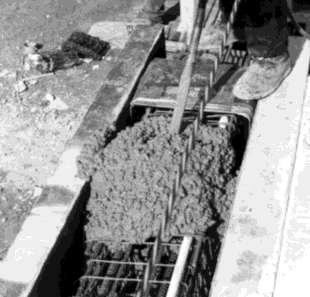
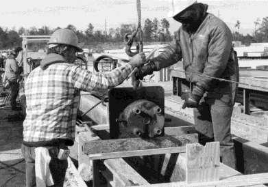
4 Driven Pile O-cell Installation O-cell cast into or welded to pile before driving O-cell grouted into pile after driving 30 PSC Pile, Morgan City, LA 66 Cylinder Pile, Harrison County, MS

 24 PHC Korea Linear & Repeatable Strain gauges")
5 O-cell Features Robust for installation Aligned with pile axis Special seal for eccentricity Water used for hydraulic fluid Rated at 10,000 psi Calibrated by AEFC (NIST Traceability) 24 PHC Korea Linear & Repeatable Strain gauges also confirm load

6 O-cell Instrumentation O-cell Pressure monitored by gauge and transducer Pile Top Movement O-cell Expansion Transducers O-cell Top Telltales Pile Bottom Telltales Embedded Strain Gauges Embedded Pile Compression Transducers


7 O-cell Test Setup ASTM D1143 Quick Test (new standard coming) 20 Loads to failure 8 min load intervals (identify creep limit) All instruments monitored by datalogger Real-time load vs. deflection plot Reference beams replaced by electronic levels

8 O-cell Sizes O-cell Size Rated Capacity Max. Test Load tons 200 tons tons 450 tons tons 875 tons tons 1400 tons tons 2250 tons tons 3100 tons tons 3900 tons tons 6000 tons Cells typically welded to load plates Cells can be grouped together 6 stroke standard, 9 stroke available
 O-cell welded")
 Rebar")

9 Special Features of Driven Pile O-cells AEFC welds plates to O-cell that fit pile form (or pile ID) O-cell welded shut for safe pile handling O-cell placed at pile bottom O-cell skirt / enclosure provided (if driven) Rebar anchors cell to pile Vent pipe to minimize disturbance at cell opening Instrumentation cables and hoses coiled at top of pile


10 Example: 18 Steel Pipe Piles, MA Saugus River Bridge Pines River Bridge Delmag D62-22 Refusal 10 blows / tons O-cell Load 0.28 tsf Side Resistance Failure (0.3 ) 80 tsf End Bearing (not failed) 284 tons Capacity Delmag D36-13 Refusal 10 blows / tons O-cell Load 0.39 tsf Side Resistance Failure (0.3 ) 122 tsf End Bearing (not failed) 430 tons Capacity
11 FL Research Pile Setup Five 18 PSC Piles PDA Tests Long-term, staged static tests (25) Osterberg Cell in tip Strain Gages Telltales Piezometers DMT Stress Cells O-cell Bottom Telltale (through center of pressure pipe) Friction Collar for Gage Support Hydraulic Pump with Gage & Piezometer Dilatometer Cell (L) & VW Piezometer (R) on Pile Face Pile Side Shear VW Strain Gage (in pairs, tied to prestress strands) Osterberg Cell Cast Into Pile, with XXS Pressure Pipe to Top O-cell Tee Wireline & Scale O-cell Top Telltales Inside PVC Pipe (not to scale) Pile End Bearing


12 FL Research Pile Setup: O-cell
 in FL 1 min 18 PSC, O-cell at bottom 0 0 50 100 150 200 250 300 Aucilla, Dynamic Test Aucilla, Static Test = 225 tons Elapsed")
13 FL Research Pile Setup Arithmetic Plot Pile Side Shear QS (kn) min min Bullock et al. (1995) in FL 1 min 18 PSC, O-cell at bottom Aucilla, Dynamic Test Aucilla, Static Test = 225 tons Elapsed Time, t (days) 1727 days
14 FL Research Pile Setup Log-linear Plot Pile Side Shear QS (kn) min (EOID Capacity plotted at 1 min) Aucilla, Dynamic Test Aucilla, Static Test = 225 tons Q S0 =1021 kn (at t 0 = 1day ) 15 min 60 min m S = kn Elapsed Time, t (days) Bullock et al. (1995) in FL 18 PSC, O-cell at bottom
15 FL Research Pile Setup Non-dimensional Plot Pile Side Shear Ratio, ( Qs / Qs0 ) A = (m S / Q S0 ) = R 2 = % 1-3d +14 % % 60 min 1-28d +43% or d about half of 15 min +30% % EOD-1d change min Aucilla, Dynamic Test Aucilla, Static Test Σ = +90% in 1 day (or 9X 1 min capacity) Bullock et al. (1995) in FL 18 PSC, O-cell at bottom Elapsed Time Ratio, ( t / t 0 ) with t 0 = 1 day


16 Example: Morgan City, LA - 30 PSC HPSI 2500, 300 bpf 30 PSC, 18 Void, 143 ft long Pile Setup Clay/Sand 950 ton O-cell Max. O-cell Load 493 tons Buoyant Pile Weight 29 tons 464 tons at 5 wks 416 tons at 3 wks 369 tons at 1wk


17 Example: Busan, Korea - 24 PHC Prestressed Spun High Strength Conc. 24 OD, 16 ID, 103 ft long, 46 ft sections Sand / Clay / Sand 875 ton O-cell, 7 Strain Levels, Grouted Max. O-cell Load 472 (944 ton test) Buoyant Pile Weight 16 tons Max. Side Shear 456 tons Unit Side Shear 0.14 to 1.98 tsf Max. End Bearing 155 tsf

 Buoyant")

18 Example: Harrison County, MS - 66 Cylinder Conmaco 300, 128 bpf EOID 66 OD, 54 ID, 108 ft long Silt / Sand / Dense Sand 3000 ton O-cell, 4 Strain Levels Max. O-cell Load 740 tons (1480 ton test) Buoyant Pile Weight 114 tons Max. Side Shear 626 tons Unit Side Shear 0.23 to 4.10 tsf Max. End Bearing 45 tsf
19 Efficient O-cell Test Applications End bearing side resistance (use ultimate!) Restricted site access (remote location, existing structures, environmentally sensitive, water) Prove capacity distribution (end bearing vs. side resistance, unit side resistance) Accelerated construction schedule Large test loads required Site safety restrictions (personnel & equipment) Repeated tests (setup) Multiple test piles (but only one test frame) Compare with total cost of conventional testing
20 O-cell Test Limitations Pile preselected for testing Maximum load limited by the weaker of the end bearing or side shear (add top load?) Top of pile not structurally tested Subtract buoyant weight of pile above O-cell to calculate side resistance Must construct equivalent top load movement curve use the sum of measured behavior use the sum of modeled behavior use finite element or t-z approach
21 Typical O-cell Test Result 2,700 tons (1 MN = tons)
22 Equivalent Top-Load Curve
23 Equiv. Top-Load + Elastic Shortening


24 RIM-CELL RIM-cell pressurizes pile cross-section Full-scale static bi-directional load test Install a RIM-cell in any pile Economical testing QA/QC device eliminates uncertainty End-bearing engaged during test, stiffens shaft response under load 60 RIM-cell
25 RIM-CELL TESTING Cross-section of a RIM-cell installed at the shaft toe.
26 RIM-CELL TESTING The RIM-cell confines the fluid pressure, creating a hydraulic cylinder at the shaft toe capable of applying high static loads.
27 RIM-CELL TESTING Fluid grout is pumped through the hydraulic hoses creating a fracture across the shaft, pressurized within the RIM-cell.

28 RIM-CELL TESTING As the internal grout sets, more grout is pumped into external pipes to fill the annular fracture around the RIM-cell.

29 USING THE RIM-CELL PROOF TEST Install in every pile Load shafts to design load or higher ( psi) Eliminate uncertainty of site variability Use higher LRFD factors Detect / remediate a soft toe POST-STRESSING Consolidate loose material at shaft toe Engage end bearing without losing side shear Limit settlement at service load


30 RIM-CELL ASSEMBLY Designed for drilled shaft construction. RIM-cell fits inside reinforcing cage. Hydraulic hoses and instrumentation pipe installed on the cage. Add strain gages, etc. to isolate and analyze different soil strata. 60 RIM-cell 24 RIM-cell installed with 8 levels of strain gages RIM-cell welded to frame below O-cell assembly for a multi-level test shaft.


31 RIM-CELL INSTALLATION After shaft excavated and approved, hang cage with RIM-cell at the desired elevation. Large center opening allows tremie pipe to pass during concrete placement. Low cross-sectional area does not inhibit concrete flow or trap loose materials. 24 RIM-cell at toe of an O-cell test shaft 20 RIM-cell installed at the toe of 30 shaft 60 RIM-cell installed into 78 rock socket

32 RIM-CELL TESTING Perform test after concrete obtains strength. Cement grout is mixed and pumped through the hydraulic hoses into the RIM-cell. Measured pressure is converted to load using calibration factor of the RIM-cell. Load is increased to 1.2 to 1.5 times design load. Shaft movement is measured and recorded. Grout will set up to restore integrity to the shaft. RIM-cell Load-Displacement Upward Top of RIM-cell Displacement ( in ) Downward Base of RIM-cell RIM-cell Load ( kips ) 24 RIM-cell Test Curve 36 RIM-cell Test Curve
33 RIM-CELL REPORTING The RIM-cell report similar to O-cell test report. Load-Displacement plot generated in real time during test. Electronic preliminary results available the same day as the test. 60 RIM-cell Schematic section of RIM-cell shaft Equivalent Top Load Plot
 Typically will not test to failure Grouting required to restore shaft integrity Maximum load limited by the weaker of the end bearing or side shear (add top")
34 RIM-CELL LIMITATIONS Internal friction unknown (but small) Preselect shaft (install in every shaft, test as required) Reduced pressure vs. O-cell (but large area) Typically will not test to failure Grouting required to restore shaft integrity Maximum load limited by the weaker of the end bearing or side shear (add top load?) Top of pile not structurally tested

35 24 RIM-CELL TESTS MISSOURI RESEARCH PROJECT 24 bi-directional test piles on two different sites Two piles on each site were tested using RIM-cells 24 RIM-cells in 36 piles feet deep shafts in unweathered and weathered shale Side by side comparison to O-cell tests
 taken to ultimate capacity.")

36 24 RIM-CELL TESTS Similar piles on same site. O-cell test (red) taken to ultimate capacity. RIM-cell test (blue) taken to design load. Plots show similar deformations at design load.

37 RIM-CELL Tests to Date RIM-cell Size Shaft Diameter Max Pressure Max Cell Load Test Result 14" 24" 2500 psi 350 kips Side Shear Failure 14" 24" 1780 psi 250 kips End Bearing Failure 20" 30" 1530 psi 450 kips Side Shear Failure 20" 30" 1360 psi 400 kips Side Shear Failure 24" 36" 2560 psi 1100 kips RIM-cell Capacity Maxed Out 24" 36" 1980 psi 850 kips RIM-cell Capacity Maxed Out 24" 36" 640 psi 275 kips End Bearing Failure 24" 36" 1170 psi 500 kips End Bearing Failure 24" 30" 940 psi 400 kips Test stopped at 1" Expansion 36" 54" 475 psi 450 kips Side Shear Failure 96" 60" (76"rock socket) 4950 psi 13,000 kips Test stopped at 1/2" Expansion
38 Summary O-cell test proven for driven piles Compare overall cost and quality of test results for conventional top-down testing with O-cell testing RIM-CELL tests to verify production pile capacity (QA/QC) Coming Attractions: New ASTM Standard Bigger piles, higher loads Mid-pile O-cell placement for spliced concrete piles Mid-pile placement for steel pipe piles

39 Thank You
SAMPLE GUIDE SPECIFICATIONS FOR OSTERBERG CELL LOAD TESTING OF DRILLED SHAFTS
 SAMPLE GUIDE SPECIFICATIONS FOR OSTERBERG CELL LOAD TESTING OF DRILLED SHAFTS 1.0 DESCRIPTION This work shall consist of furnishing all materials and labor necessary for conducting an Osterberg Cell (O-cell)
REPORT ON DRILLED SHAFT LOAD TESTING (OSTERBERG METHOD) I-215 Airport Connector - Las Vegas, NV - TS-1 Las Vegas, NV (LT )
 I-215 Airport Connector - Las Vegas, NV - TS-1 Las Vegas, NV (LT )") REPORT ON DRILLED SHAFT LOAD TESTING (OSTERBERG METHOD) I-215 Airport Connector - Las Vegas, NV - TS-1 Las Vegas, NV (LT - 9289) Prepared for: Anderson Drilling 2545 S. Bruce Street, Suite H1 Las Vegas,
REPORT ON DRILLED SHAFT LOAD TESTING (OSTERBERG METHOD) I-215 Airport Connector - Las Vegas, NV - TS-1 Las Vegas, NV (LT - 9289) Prepared for: Anderson Drilling 2545 S. Bruce Street, Suite H1 Las Vegas,
Bi-Directional Static Load Testing of Drilled Shafts
 Supplemental Technical Specification for Bi-Directional Static Load Testing of Drilled Shafts SCDOT Designation: SC-M-712 (9/15) September 2, 2015 1.0 GENERAL This work shall consist of furnishing all
Bi-Directional Static Load Testing of Drilled Shafts
 Supplemental Technical Specification for Bi-Directional Static Load Testing of Drilled Shafts SCDOT Designation: SC-M-712 (01/18) 1.0 GENERAL This work shall consist of furnishing all materials, equipment,
O-CELL TESTING CASE HISTORIES DEMONSTRATE THE IMPORTANCE OF BORED PILE (DRILLED SHAFT) CONSTRUCTION TECHNIQUE
 CONSTRUCTION TECHNIQUE") O-CELL TESTING CASE HISTORIES DEMONSTRATE THE IMPORTANCE OF BORED PILE (DRILLED SHAFT) CONSTRUCTION TECHNIQUE John H. Schmertmann John A. Hayes Paper No. 81 Professor Emeritus President, LOADTEST, Inc.
O-CELL TESTING CASE HISTORIES DEMONSTRATE THE IMPORTANCE OF BORED PILE (DRILLED SHAFT) CONSTRUCTION TECHNIQUE John H. Schmertmann John A. Hayes Paper No. 81 Professor Emeritus President, LOADTEST, Inc.
Evaluation of PDA Data to Identify Pile Issues Presented at Annual KC Specialty Seminar January 9, 2015
 Evaluation of PDA Data to Identify Pile Issues Presented at Annual KC Specialty Seminar January 9, 2015 Presentation Topics Overview of PDA data collection Case histories for how PDA testing reduced the
Conference: IFCEE International Foundations Congress and Equipment Exposition
 Conference: IFCEE2018 - International Foundations Congress and Equipment Exposition Paper Title: Bonner Bridge Replacement Project - Pile Driving Experience Authors: Scott Webster 1, Karen Webster 2 1
STATNAMIC LOAD TESTING OF HIGH CAPACITY MARINE FOUNDATIONS
 STATNAMIC LOAD TESTING OF HIGH CAPACITY MARINE FOUNDATIONS Mike Muchard, P.E., Applied Foundation Testing, Inc., Tampa, FL, USA STATNAMIC load testing augmented with embedded instrumentation has been successfully
CASE STUDY: LOAD TRANSFER ANALYSIS ON AN INSTRUMENTED AUGERCAST PILE USING EDC STRAIN GAUGES AND GEOKON REBAR STRAINMETERS
 CASE STUDY: LOAD TRANSFER ANALYSIS ON AN INSTRUMENTED AUGERCAST PILE USING EDC STRAIN GAUGES AND GEOKON REBAR STRAINMETERS Swamy Avasarala 1, Santosh Mummaneni 2, Vamshi Vemula 3, Dr. Sastry Putcha 4 1
SECTION DUCTILE IRON PILES
 SECTION 31 66 13 DUCTILE IRON PILES PART 1 - GENERAL 1.1 GENERAL REQUIREMENTS A. Work of this Section, as shown or specified, shall be in accordance with the requirements of the Contract Documents. B.
Steven Dapp, Ph.D., P.E. Steven Dapp, Ph.D., P.E. Dan Brown and Associates
 LA Transportation Conference: 10 Jan 2011 Drilled Shaft Foundations For Two Mississippi River Bridges in Louisiana Dan Brown and Associates Projects John James Audubon Bridge, St. Francisville New Construction
Rapid Axial Load Testing of Drilled Shafts
 Supplemental Technical Specification for Rapid Axial Load Testing of Drilled Shafts SCDOT Designation: SC-M-712 (9/15) September 4, 2015 1.0 GENERAL This work shall consist of performing a rapid axial
Tip-Grouted Drilled Shaft Foundations for the Audubon Bridge. Acknowledgements
 Tip-Grouted Drilled Shaft Foundations for the Audubon Bridge Steven Dapp, Ph.D., P.E. Dan Brown, Ph.D., P.E. www.danbrownandassociates.com Acknowledgements Tip grouting used worldwide for more than 3 decades.
Deep Foundation Testing, Analysis and Consulting Services
 Deep Foundation Testing, Analysis and Consulting Services PDA Testing and Monitoring Dynamic Load Testing- APPLE Thermal Integrity Testing Crosshole Sonic Logging SPT Energy Calibration Low Strain Integrity
Typical set up for Plate Load test assembly
 Major disadvantages of field tests are Laborious Time consuming Heavy equipment to be carried to field Short duration behavior Plate Load Test Sand Bags Platform for loading Dial Gauge Testing Plate Foundation
Soil-Structure Interaction (SSI) Testing Facility and Capabilities at Lehigh University
 Testing Facility and Capabilities at Lehigh University") Soil-Structure Interaction (SSI) Testing Facility and Capabilities at Lehigh University Muhannad T. Suleiman, Ph.D. Associate Professor Civil and Environmental Engineering Department 1 SSI Testing Facility
Soil-Structure Interaction (SSI) Testing Facility and Capabilities at Lehigh University Muhannad T. Suleiman, Ph.D. Associate Professor Civil and Environmental Engineering Department 1 SSI Testing Facility
Pile Driving Analyzer (PDA) and CAPWAP Proven Pile Testing Technology: Principles and Recent Advances
 and CAPWAP Proven Pile Testing Technology: Principles and Recent Advances") Pile Driving Analyzer (PDA) and CAPWAP Proven Pile Testing Technology: Principles and Recent Advances Frank Rausche, Ph.D., P.E. Pile Dynamics, Inc. 2013 Louisiana Transportation Conference 1 Introduction
Pile Driving Analyzer (PDA) and CAPWAP Proven Pile Testing Technology: Principles and Recent Advances Frank Rausche, Ph.D., P.E. Pile Dynamics, Inc. 2013 Louisiana Transportation Conference 1 Introduction
RIGOLETS PASS BRIDGE ~ TEST PILE PROGRAM
 RIGOLETS PASS BRIDGE ~ TEST PILE PROGRAM By: Chris Nickel, P.E. LA DOTD Pavement & Geotechnical Services BACKGROUND ~This state project consists of the construction of the new Rigolets Pass Bridge located
RIGOLETS PASS BRIDGE ~ TEST PILE PROGRAM
 RIGOLETS PASS BRIDGE ~ TEST PILE PROGRAM By: Chris Nickel, P.E. By: Chris Nickel, P.E. LA DOTD Pavement & Geotechnical Services BACKGROUND ~This state project consists of the construction of the new Rigolets
Innovation in Instrumented Test Piles in Malaysia: Application of Global Strain Extensometer (GloStrExt) Method for Bored Piles
 Method for Bored Piles") Innovation in Instrumented Test Piles in Malaysia: Application of Global Strain Extensometer (GloStrExt) Method for Bored Piles... By: Dr H.M. Abdul Aziz bin K.M Hanifah 1 and Lee Sieng Kai 2 (GIEM) 1
Innovation in Instrumented Test Piles in Malaysia: Application of Global Strain Extensometer (GloStrExt) Method for Bored Piles... By: Dr H.M. Abdul Aziz bin K.M Hanifah 1 and Lee Sieng Kai 2 (GIEM) 1
Deep Water Drilled Shafts for the Herrington Lake Bridge Replacement Project
 Deep Water Drilled Shafts for the Herrington Lake Bridge Replacement Project Darrin Beckett, P.E. Kentucky Transportation Cabinet 49 th Southeastern Transportation Geotechnical Engineering Conference October
STATE-OF-THE-ART TECHNOLOGY OF Y-JACK IN BI-DIRECTIONAL PILE TEST
 STATE-OF-THE-ART TECHNOLOGY OF Y-JACK IN BI-DIRECTIONAL PILE TEST SL, Yu 1 and Yekong, Wai 2 ABSTRACT: The innovative pile testing that is categorized as a bi-directional test method (BD) obtained worldwide
Using Load Testing to Save Money and Time on the I-35W Bridge Project
 Using Load Testing to Save Money and Time on the I-35W Bridge Project MATTHEW GLISSON, PE, M.ASCE, Braun Intertec Corporation, St. Louis, MO; MORGAN RACE, PH.D., PE, M.ASCE, Braun Intertec Corporation,
560 IN SITU TESTING, ANALYSIS, AND RELIABILITY OF FOUNDATIONS. Lateral Load Capacity of Cast-in-Place Shafts behind an MSE Wall. *corresponding author
 56 IN SITU TESTING, ANALYSIS, AND RELIABILITY OF FOUNDATIONS Lateral Load Capacity of Cast-in-Place Shafts behind an MSE Wall Robert L. Parsons, M.ASCE, P.E. 1*, Matthew Pierson 2, Jie Han, M.ASCE, P.E.
Experimental study on axial and lateral bearing capacities of nonwelded composite piles based on pile load test results
 NGM 2016 Reykjavik Proceedings of the 17 th Nordic Geotechnical Meeting Challenges in Nordic Geotechnic 25 th 28 th of May Experimental study on axial and lateral bearing capacities of nonwelded composite
3.1 Scope of the work-capacity Estimation of Drilled Shaft Bearing on Rock
 Chapter 3-Methodology 3.1 Scope of the work-capacity Estimation of Drilled Shaft Bearing on Rock The research work involved the use of high strain dynamic stress wave measurements for capacity estimation
STANDARDIZED STRUCTURES
 Q, QH & QL TOWERS 16.1 Q, QH, and QL Towers General Description The series includes three and four leg angle towers, which are suited for a variety of antenna mounting positions and load conditions. The
Overburden Effect on the Axial Resistance of Instrumented CFA Piles. Knoxville, TN 37922, ph ,
 703 Overburden Effect on the Axial Resistance of Instrumented CFA Piles Timothy C. Siegel 1, M. ASCE, P.E., G.E., D.GE and Peter Faust 2 1 Principal Engineer, Dan Brown and Associates, PC, 1808 Northshore
DIAPHRAGM WALLS, CUT-OFF WALLS AND SLURRY WALLS
 DIAPHRAGM WALLS, CUT-OFF WALLS AND SLURRY WALLS Implenia Spezialtiefbau GmbH Robert Bosch Straße 25 D-63225 Langen Phone: +49 6103 988 345 Fax: +49 6103 988 277 Email: info.spezialtiefbau@implenia.com
Pier Pressure in Natchez, Mississippi Post Grouted Drilled Shafts Pass Test
 COVER FEATURE Pier Pressure in Natchez, Mississippi Post Grouted Drilled Shafts Pass Test by Mike Muchard, P.E. Applied Foundation Testing, Inc. Introduction Post grouting of drilled shaft tips as a means
SAMPLE SPECIFICATION for HIGH STRAIN DYNAMIC TESTING of DRIVEN PILES
 SAMPLE SPECIFICATION for HIGH STRAIN DYNAMIC TESTING of DRIVEN PILES October 2014 In using this sample specification, it should be recognized that each site and structure is unique. Therefore, geotechnical
UPDATE ON ISU DRILLED SHAFT LRFD CALIBRATION STUDY. Jeramy C. Ashlock, Ph.D. Richard L. Handy Associate Professor
 UPDATE ON ISU DRILLED SHAFT LRFD CALIBRATION STUDY Jeramy C. Ashlock, Ph.D. Richard L. Handy Associate Professor jashlock@iastate.edu Ongoing Drilled Shaft Research Projects 2 1.Verification of LRFD Resistance
Pile Driving Issues. Mark McClelland, P.E. Geotechnical Branch Manager Texas DOT
 Pile Driving Issues Mark McClelland, P.E. Geotechnical Branch Manager Texas DOT Goldilocks?? This soil it too hard This soil is too soft This soil is just right! This soil is too hard Prestressed concrete
Post-Grouting of Drilled Shaft Tips on the Sutong Bridge: A Case History
 Post-Grouting of Drilled Shaft Tips on the Sutong Bridge: A Case History Dr. Osama Safaqah 1, P.E., Robert Bittner 2, P.E. & Xigang Zhang 3 1 Project Manager, Ben C. Gerwick, Inc., 20 California Street,
THE STUDY OF t-z AND q-z CURVES ON BORED PILE BASED ON THE RESULTS OF INSTRUMENTED PILE LOAD TEST IN MEDIUM AND STIFF CLAYS
 Proceedings of Pile 2013, June 2-4 th 2013 THE STUDY OF t-z AND q-z CURVES ON BORED PILE BASED ON THE RESULTS OF INSTRUMENTED PILE LOAD TEST IN MEDIUM AND STIFF CLAYS Aswin Lim 1, Aksan Kwanda 2 and Paulus
EXPERIENCES WITH BASE GROUTED DRILLED SHAFTS IN THE
 EXPERIENCES WITH BASE GROUTED DRILLED SHAFTS IN THE SOUTHEASTERN UNITED STATES Steven D. Dapp, Ph.D., P.E., Dan A. Brown and Associates, Sequatchie, Tennessee, U.S.A. Mike Muchard, P.E., Applied Foundation
Testing Methods of Driven Piles on INDOT Demonstration Projects
 66 Testing Methods of Driven Piles on INDOT Demonstration Projects by Firooz Zandi, P.E. Chief Geotechnical Engineer Division of Materials & Tests, I NDOT INTRODUCTION: This paper provides an overview
VW Total Pressure Cell
 VW Total Pressure Cell 52608299 Copyright 2004 Slope Indicator Company. All Rights Reserved. This equipment should be installed, maintained, and operated by technically qualified personnel. Any errors
Design and Construction of Drilled Full Displacement Piles using the Penetration Resistance Method
 SUPERPILE 2009 Burlingame, CA Design and Construction of Drilled Full Displacement Piles using the Penetration Resistance Method Peter Faust Malcolm Drilling Company Inc. Alexandria Parking Garage, San
Comparative Study between Design Methods and Pile Load Tests for Bearing Capacity of Auger-drilled PHC Piles
 Comparative Study between Design Methods and Pile Load Tests for Bearing Capacity of Auger-drilled PHC Piles Jae-Kwan KIM, Jung-Yup HYUN, Jong-Ju KIM Civil Engineering Team SK E&C 66 Sun-hwa Dong, Seoul,
MODEL SPECIFICATIONS: Hydraulically Driven Steel Underpinning Pile Specifications
 MODEL SPECIFICATIONS: Hydraulically Driven Steel Underpinning Pile Specifications Mar/2008 v1.0 SECTION 02255 HYDRAULICLY DRIVEN STEEL UNDERPINNING PILES PART 1 GENERAL 1.01 SCOPE OF WORK The work shall
Analysis of Four Load Tests on Augered Cast-in-Place Piles in the Texas Gulf Coast Soils Raghu Dass, PE, Woodward Vogt, PE, and Frank Ong, PE
 Analysis of Four Load Tests on Augered Cast-in-Place Piles in the Texas Gulf Coast Soils Raghu Dass, PE, Woodward Vogt, PE, and Frank Ong, PE Presented By: Raghu N. Dass, Ph. D., P.E. TSI Laboratories,
Foundation Innovations Ensure Successful Bridge Replacement
 COVER STORY Foundation Innovations Ensure Successful Bridge Replacement Rhode Island s new $163.7 million, 2,265 ft (690 m) long, fourlane Sakonnet River Bridge sits just south of the existing bridge in
DESIGN-BUILD-TEST PROCESS FOR HIGH CAPACITY MICROPILES: CONSTRUCTION CASE STUDY ON DUTCHESS RAIL TRAIL BRIDGE FOUNDATIONS, POUGHKEEPSIE, NEW YORK
 ABSTRACT DESIGN-BUILD-TEST PROCESS FOR HIGH CAPACITY MICROPILES: CONSTRUCTION CASE STUDY ON DUTCHESS RAIL TRAIL BRIDGE FOUNDATIONS, POUGHKEEPSIE, NEW YORK James Barron 1, P.E., Thomas Hattala 2, P.E.,
Ching Guan Kee ABSTRACT
 Japanese Geotechnical Society Special Publication The 15th Asian Regional Conference on Soil Mechanics and Geotechnical Engineering Effects of base grouting and deep cement mixing on deep foundation bored
On-site determination of pile capacity Distribution of pile load between the shaft and tip, and Detection of possible pile.
 Pile Load Test Pile foundation can be constructed depending on the stiffness of subsurface soil and ground water conditions and using a variety of construction techniques. The most common techniques are
FOUNDATIONS. Foundations Copyright G G Schierle, 2006 Press Esc to end, for next, for previous slide 1
 FOUNDATIONS Foundations Copyright G G Schierle, 2006 Press Esc to end, for next, for previous slide 1 Liquefaction reduced the soil strength under these apartment buildings in Niigata (Japan) 1964. Liquefaction
APPENDIX 1 Homework - 20 Problems
 APPENDIX 1 Homework - 20 Problems Florida Department of TRANSPORTATION Homework 1. The scour elevation can normally be found on the bridge hydraulics sheet and in the Pile Data Table. True False 2. The
SPECIAL SPECIFICATION 4492 Tie Back Anchors
 2004 Specifications CSJ 0504-02-022 SPECI SPECIFICATION 4492 Tie Back Anchors 1. Description. This Item shall govern for the installation of tie-back anchors in place, with grouting as required in accordance
CHAPTER III DYNAMIC BEHAVIOR OF A LABORATORY SPECIMEN
 CHAPTER III DYNAMIC BEHAVIOR OF A LABORATORY SPECIMEN To address the vibration response of a long span deck floor system, an experiment using a specimen that resembles the conditions found in the in-situ
The experience in applying of static load and O-cell pile testing geotechnologies in problematical soil conditions of Astana
 Japanese Geotechnical Society Special Publication International Mini Symposium CHUBU (IMS-CHUBU) The experience in applying of static load and O-cell pile testing geotechnologies in problematical soil
OFFICE OF STATE AID ROAD CONSTRUCTION MISSISSIPPI DEPARTMENT OF TRANSPORTATION
 Supplemental Specification 901-S-803-1 LFRD Driven Pile Specifications. DATE: May 24, 2010 OFFICE OF STATE AID ROAD CONSTRUCTION MISSISSIPPI DEPARTMENT OF TRANSPORTATION SUBJECT: LRFD Driven Pile Specifications
Pipe Ramming with HDD. Presentation Outline
 EXAMINING PIPE RAMMING DESIGN- A FORENSIC ANALYSIS OF A HIGH RISK PROJECT Kimberlie Staheli, Ph.D., P.E. Staheli Trenchless Consultants Seattle, WA, USA Presentation Outline Pipe Ramming State of the Art
SPECIAL SPECIFICATION 4401 Prestressed Ground Anchors
 2004 Specifications CSJ 0581-02-121 & 0200-11-100 SPECI SPECIFICATION 4401 Prestressed Ground Anchors 1. Description. Install post-tensioned permanent ground anchors in place, with grouting as required
Method Statement of load Test for Steel Tubular Load Test Trial Piles Rev.3
 Doc. No.: PMBP-MBEC-MS-SZ001 Rev. No.: Third Issue Date:23-03-2015 Method Statement of load Test for Steel Tubular Load Test Trial Piles Rev.3 3 23-03-2015 LSC Revised Issue LYF MYG YBJ 2 20-02-2015 LSC
Experimental study on axial and lateral bearing capacities of nonwelded composite piles based on pile load test results
 NGM 2016 Reykjavik Proceedings of the 17 th Nordic Geotechnical Meeting Challenges in Nordic Geotechnic 25 th 28 th of May Experimental study on axial and lateral bearing capacities of nonwelded composite
Pile Design from Constructability Perspective
 Pile Design from Constructability Perspective Prestressed Concrete Piles in Coastal Georgia Presented by: Guoming Lin, Ph.D., G.E., D.GE Senior Principal / Senior Consultant Savannah, Georgia November
Lantz-Boggio Architects, P.C LBA Project No
 SECTION 313430- PART 1 GENERAL 1.1 WORK INCLUDED A. Provide all equipment, material, labor and supervision to design and install Engineered Aggregate Piers for the soil reinforcement. Design shall rely
1. Cast-in-place concrete is specified in Section
 SECTION 03 38 00 PART 1 - GENERAL 1.01 DESCRIPTION A. This Section describes the requirements for furnishing and installing post-tensioned slabs, jacks, jacking and anchors at Parking Structure, and record
Malaysian Journal of Civil Engineering 27 Special Issue (1):1-18 (2015)
:1-18 (2015)") Malaysian Journal of Civil Engineering 27 Special Issue (1):1-18 (2015) COMPARATIVE STUDY OF LARGE DIAMETER BORED PILE UNDER CONVENTIONAL STATIC LOAD TEST AND BI-DIRECTIONAL LOAD TEST Vinsensius Viktor
Malaysian Journal of Civil Engineering 27 Special Issue (1):1-18 (2015) COMPARATIVE STUDY OF LARGE DIAMETER BORED PILE UNDER CONVENTIONAL STATIC LOAD TEST AND BI-DIRECTIONAL LOAD TEST Vinsensius Viktor
Our Tour Stops. A Foundation Engineering gtrip down the Mississippi River. Dan Brown, P.E. Dan Brown and Associates 9/6/2010.
 A Foundation Engineering gtrip down the Mississippi River Dan Brown, P.E. Dan Brown and Associates Our Tour Stops I 35W Minneapolis US U.S. 61 Bridge, Hastings, MN New Mississippi River Bridge (I 70),
John James Audubon Bridge
 John James Audubon Bridge Cable-Stayed Main Span Over the Mississippi River Johns Hopkins University Whiting School of Engineering September 10, 2008 The Project Scheduled Time to Complete Estimated Number
twenty six concrete construction: foundation design ELEMENTS OF ARCHITECTURAL STRUCTURES: FORM, BEHAVIOR, AND DESIGN DR. ANNE NICHOLS SPRING 2013
 ELEMENTS OF ARCHITECTURAL STRUCTURES: FORM, BEHAVIOR, AND DESIGN DR. ANNE NICHOLS SPRING 2013 lecture twenty six concrete construction: www.tamu.edu foundation design Foundations 1 Foundation the engineered
INTERPRETATIONS OF INSTRUMENTED BORED PILES IN KENNY HILL FORMATION
 INTERPRETATIONS OF INSTRUMENTED BORED PILES IN KENNY HILL FORMATION S. S. Liew 1, Y. W. Kowng 2 & S. J. Gan 3 ABSTRACT This paper presents the results of two instrumented bored cast-in-situ test piles
Typical Specifications of Compaction Grouting Scope
 Typical Specifications of Compaction Grouting Scope This section covers compaction with Sand/Cement/Flyash grout including the installation of injection pipes. Compaction grouting is sometimes referred
A Case History of Pile Freeze Effects in Dense Florida Sands
 A Case History of Pile Freeze Effects in Dense Florida Sands By Ching Kuo 1, Guoan Cao 2, Amy L. Guisinger 3, and Paul Passe 4 Submission Date: August 1, 2006 2,804 Words 1 Table 5 Figures 1 Professional
RECORD KEEPING AND INSPECTION NOTES FOR FUTURE NEEDS
 RECORD KEEPING AND INSPECTION NOTES FOR FUTURE NEEDS Chris Nickel, P.E. LA DOTD Pavement & Geotechnical Services 2011 Louisiana Engineering Conference TOPIC OUTLINE Driven Piles Definitions and Data table
CONTINUOUS FLIGHT AUGER (CFA) PILES QC/QA PROCEDURES. Preferred QC/QA Procedures
 PILES QC/QA PROCEDURES. Preferred QC/QA Procedures") Preferred QC/QA Procedures The Federal Highway Administration (FHWA) has provided QC/QA guidance for this technology as noted below. The reference document also contains information about construction
Preferred QC/QA Procedures The Federal Highway Administration (FHWA) has provided QC/QA guidance for this technology as noted below. The reference document also contains information about construction
Proper Practice. 2015, Pile Dynamics, Inc.
 PDA Testing : Proper Practice 1997 1958 1965 1992 1982 2014 1973 2007 2015, Pile Dynamics, Inc. Luckily, no fatalities but sure slows job down NOTHING is more important than your safety! If you perceive
Anchor Load Cells Installation - considerations
 Anchor Load Cells Installation - considerations This article outlines the main points to check during installation of load cells to control tensions while installing and service life, applied on bar and
Deep Foundation. Deep Foundation Applications
 Deep Foundation Deep Foundation Applications 1. Soils with: High compression Low shear strength Swelling/shrinkage 2. Resist lateral loads 3. Surface erosion 4. Resist tension (anchors) 1 Typical Applications
twenty four foundations and retaining walls Foundation Structural vs. Foundation Design Structural vs. Foundation Design
 ALIED ARCHITECTURAL STRUCTURES: STRUCTURAL ANALYSIS AND SYSTEMS DR. ANNE NICHOLS SRING 2018 lecture twenty four Foundation the engineered interface between the earth and the structure it supports that
Misan University - College of Engineering Civil Engineering Department
 CHAPTER 2 Soil and Excavations Soil investigation including two phases: surface investigation and subsurface investigation Surface investigation involves making a preliminary judgment about the site s
Non-destructive Testing of Installed Soil Nails Using Sonic Echo Test Method
 Non-destructive Testing of Installed Soil Nails Using Sonic Echo Test Method Specifications for Grouting Mixtures and Procedures for Soil Nail Installations Research Project Number 0-4484 Research Product
In-plane testing of precast concrete wall panels with grouted sleeve
 In-plane testing of precast concrete wall panels with grouted sleeve P. Seifi, R.S. Henry & J.M. Ingham Department of Civil Engineering, University of Auckland, Auckland. 2017 NZSEE Conference ABSTRACT:
APPENDIX B. LOAD FRAME. This Appendix will describe the philosophy in the design and operation of the loading system.
 APPENDIX B. LOAD FRAME This Appendix will describe the philosophy in the design and operation of the loading system. LOAD FRAME The large-scale gusset plate testing required a unique loading fixture. A
This document downloaded from vulcanhammer.net vulcanhammer.info Chet Aero Marine
 This document downloaded from vulcanhammer.net vulcanhammer.info Chet Aero Marine Don t forget to visit our companion site http://www.vulcanhammer.org Use subject to the terms and conditions of the respective
twenty seven concrete construction: foundation design Foundation Structural vs. Foundation Design Structural vs. Foundation Design
 ARCHITECTURAL STRUCTURES: FORM, BEHAVIOR, AND DESIGN DR. ANNE NICHOLS SRING 2017 lecture twenty seven Foundation the engineered interface between the earth and the structure it supports that transmits
High strain dynamic testing in micropiles. Comparison of static and dynamic test results
 High strain dynamic testing in micropiles. Comparison of static and dynamic test results Oteo, C. Dpto. Ingeniería del Terreno, A Coruña University, A Coruña, Spain Arcos, J.L. & Gil, R. Kronsa Internacional,
Safe, fast and simple: the DUKTUS pile is loadtested in South Africa
 Safe, fast and simple: the DUKTUS pile is loadtested in South Africa Prof SW Jacobsz Dept Civil Engineering University of Pretoria sw.jacobsz@up.ac.za Dave Rossiter Chairman GeoGroup info@geogroup.co.za
SECTION / ENGINEERED AGGREGATE PIERS (SOIL REINFORCEMENT AND FOUNDATION SYSTEM)
") PART 1 GENERAL 1.01 WORK INCLUDED SECTION 02360 / 31 34 30.13 ENGINEERED AGGREGATE PIERS (SOIL REINFORCEMENT AND FOUNDATION SYSTEM) A. Provide all equipment, material, labor and supervision to design and
PART 1 GENERAL 1.01 WORK INCLUDED SECTION 02360 / 31 34 30.13 ENGINEERED AGGREGATE PIERS (SOIL REINFORCEMENT AND FOUNDATION SYSTEM) A. Provide all equipment, material, labor and supervision to design and
Soil Improvement by Compaction Grouting
 CITY AND COUNTY OF DENVER ENGINEERING DIVISION Wastewater Capital Projects Management Standard Construction Specification 31-3223.12 Soil Improvement by Compaction Grouting Part 1 - General 1.01 Introduction
Lesson 7 REINFORCING CAGE. Version 1-1/
 Lesson 7 REINFORCING CAGE 7-1 Version 1-1/15 7-1 Learning Outcomes Describe cage construction Determine the circumference of a shaft and rebar cage and calculate the required number of side spacers. Explain
Deep Foundations By. J. Paul Guyer, P.E., R.A. PDHLibrary Course No PDH HOURS
 Deep Foundations By J. Paul Guyer, P.E., R.A. PDHLibrary Course No 0010051 3 PDH HOURS An Introduction to Deep Foundations Guyer Partners 44240 Clubhouse Drive El Macero, CA 95618 (530) 758-6637 jpguyer@pacbell.net
LADOTD DRIVEN PILE DESIGN & VERIFICATION. Jesse G Rauser, PE USING LRFD
 LADOTD DRIVEN PILE DESIGN & VERIFICATION Jesse G Rauser, PE USING LRFD OBJECTIVES Not all of our policies, guidelines, and SOP s are in the same location Answer commonly asked questions about LADOTD pile
Construction Planning, Equipment, and Methods PILES AND PILE-DRIVING EQUIPMENT
 CHAPTER Construction Planning, Equipment, and Methods PILES AND PILE-DRIVING EQUIPMENT Sixth Edition A. J. Clark School of Engineering Department of Civil and Environmental Engineering 19 By Dr. Ibrahim
SUPPLEMENTAL TECHNICAL SPECIFICATION
 July 14, 2015 HIGH STRAIN DYNAMIC LOAD TESTING OF DRILLED SHAFTS 1.0 GENERAL This work shall consist of performing high-strain dynamic testing using a drop weight loading system on a test drilled shaft
Deflection of Helical Piles: A Load Test Database Review
 Proceedings of 1st International Geotechnical Symposium on Helical Foundations, The International Society for Helical Foundations, August 2013, University of Massachusetts, Amherst, MA, USA Deflection
PAUL ZICK, PE NORTH SHORE CONSTRUCTORS JV
 NORTH SHORE CONNECTOR TUNNELS AND STATION SHELL LIGHT RAIL PROJECT PAUL ZICK, PE NORTH SHORE CONSTRUCTORS JV North Shore Connector Alignment 7300 lf Extension to existing 25 mile system 18 Contracts $435
USE OF DIPP PILES FOR A NEW SUP BRIDGE IN WEST MELBOURNE
 USE OF DIPP PILES FOR A NEW SUP BRIDGE IN WEST MELBOURNE If you want to put a photo on the title slide use this layout with colour photos (delete this box) Michael Wei, Jawad Zeerak & David Barton 8 th
Penang Second Bridge
 Penang Second Bridge Marine Bridge Substructure Construction Spun Pile Main Span Pilecap Construction by Ir. Cheng Kim Bong Senior Resident Engineer MMSB Consult Sdn. Bhd. Content Penang Second Bridge
Dynamic Testing Applications for driven piles using Pile Driving Analyzer & CAPWAP
 Dynamic Testing Applications for driven piles using Pile Driving Analyzer & CAPWAP by Garland Likins Pile Dynamics, Inc. Cleveland, OH, USA 2013, Pile Dynamics, Inc. Load Testing. Static Load Testing ASTM
Chapter 21 GEOTECHNICAL REPORTS
 Chapter 21 GEOTECHNICAL REPORTS Final SCDOT GEOTECHNICAL DESIGN MANUAL June 2010 Table of Contents Section Page 21.1 Introduction... 21-1 21.2 Geotechnical Base Line Report... 21-1 21.3 Bridge Geotechnical
HMA GROUP AUSTRALIA - NEW ZEALAND - INDONESIA - SOUTH AFRICA SINCE 1966
 SINCE 1966 Introduction Geotechnical Systems Australia (GSA) was founded in March 1987 to design, manufacture and distribute geotechnical instrumentation for the geotechnical and mining industries. Now
Multi-Institutional Academic Health Science & Research Center Evansville, IN
 SECTION 02370 AUGER CAST PILES PART 1 - GENERAL 1.1 SECTION INCLUDES: The work covered by these specifications consists of furnishing all labor, equipment and materials for the installation of auger cast
1.364 ADVANCED GEOTECHNICAL ENGINEERING HOMEWORK No. 5
 .364 ADVANCED GEOTECHNICAL ENGINEERING HOMEWORK No. Due: Friday December 2. This question concerns the stability of an open slope cutting that will be used to provide construction access for a 3.2m deep
MICROPILE LATERAL LOAD TESTING IN CHARLESTON, SOUTH CAROLINA, USA
 MICROPILE LATERAL LOAD TESTING IN CHARLESTON, SOUTH CAROLINA, USA William B. Wright, et. al. 1 ABSTRACT With increasing frequency, micropiles are being used as a foundation solution within the Charleston,
Florida Method of Test for NONREPETITIVE STATIC PLATE LOAD TEST OF SOILS AND FLEXIBLE PAVEMENT COMPONENTS
 Florida Method of Test for NONREPETITIVE STATIC PLATE LOAD TEST OF SOILS AND FLEXIBLE PAVEMENT COMPONENTS 1. SCOPE Designation: FM 5-527 Modified AASHTO T-222-78 1.1 This method covers the making of nonrepetitive
Concrete Prestressed Concrete Pretensioned Concrete Posttensioned Concrete Typical Tendon Layout
 Concrete 45 1.13.0 Prestressed Concrete Concrete in which internal stresses (forces) are induced by means of prestressing steel tendons such that tensile stresses resulting from loads are counteracted