SPECIFICATION FOR ELECTRICAL INSTALLATION
|
|
|
- Harry Clarke
- 6 years ago
- Views:
Transcription
1 SPECIFICATION FOR ELECTRICAL INSTALLATION SUBDIVISION AND TOWNHOME DEVELOPMENTS (Revision1: March 2011) Brantford Power Inc. Engineering and Construction 84 Market St., P.O. Box 308, Brantford, Ont., N3T 5N8 Telephone: (519) ; Fax: (519)
2 Table of Contents Section Page 1.0 SCOPE DEFINITIONS GENERAL CONDITIONS Easements Consulting Engineer Contractor Design Requirement Specifications for Drafting Plan View Schematic Reproducible Copies Pre-construction Requirement Inspector s Authority On-site Inspection and Testing Remedial Work Ordering and Handling Material Service Installation and Metering on Residential Lots Location of Trenches Location of Equipment Location of Road Crossings Pre-energization Requirement Site Safety Warranty Period INSTALLATION OF ELECTRICAL PLANT Trench Excavations and Backfilling Joint Use of Trenches Concrete for Foundations and Ducts Installation of Ducts Direct Buried Installation Concrete Encased Installation Installation Capacity Road Crossings Cable Installation Installation of Secondary Cables Termination and Connection of Secondary Cables 17
3 Section Table of Contents Page Installation of Primary Cables Termination of Primary Cable Testing Installation of Neutral Warning Tape / Electronic Marker Installation of System Ground Installation of Transformers Transformer Location Transformer Vaults Orientation and Placement Installation of Switchgear Installation of Primary Dip pole(s) 22 APPENDICES A. Drawings showing Standard Installation Practices B. Drawings showing Standard Drafting Practices C. Transformer Specification D. Primary and Secondary Cable Specifications E. Catalog Numbers of Approved Equipment F. Cable High Potential Test
4 Subdivision and Townhome Developments March SCOPE This specification is supplemental to the City of Brantford Agreements with developers of Subdivisions and / or Townhomes, as well as Brantford Power Inc. s Conditions of Service and is intended to cover underground service(s) to detached, semi-detached or row units on blocks of land where primary service is available only at the edge(s) of the land containing these development properties. The supply point(s) of power shall be from Brantford Power Inc.'s designated source(s). All facilities beyond this (these) point(s) towards the load, including lines, shall be installed, and paid for by the Developer through a capital contribution model as prescribed by the Ontario Energy Board. The subsequent ownership and maintenance of Electrical Plant up to the Residential Customer(s) meter base(s) shall remain with Brantford Power Inc. as per the provisions in our Conditions of Service. This specification covers Subdivisions and Townhomes sites serviced with a primary voltage of 27.6 /16 kv only. The Developer or his representative must contact Brantford Power Inc. Engineering and Construction department regarding any other special requirements. In the case of a conflict between this specification and drawing approved by Brantford Power Inc., the approved drawing shall prevail, unless advised otherwise by Brantford Power. 2.0 DEFINITIONS Development shall include all parcels of land that have been approved by the City of Brantford as a Subdivision or Townhomes site. "Owner" shall include the applicant for the approval of a Subdivision or Townhomes Development and the registered owner or owners in fee simple of the lands for which the Subdivision or Townhomes Development is proposed, and/or their respective heirs, executors, administrators, and assigns and in addition to its accepted meaning, shall mean and include an individual, an association, a partnership, or an incorporated company. "Consulting Engineer" shall mean the person or persons, registered with the Association of Professional Engineers of Ontario, who for the time being, are employed to provide engineering services on behalf of the Owner. "BPI" shall mean Brantford Power Inc. "Electrical Plant" shall mean the total electrical distribution system, and appurtenances owned and maintained by BPI, from its designated point(s) of supply to the ownership demarcation point(s) at the meter base. Inspector shall mean the person appointed by Brantford Power Inc. to inspect and/or approve the owner s installations in the subdivision. Contractor shall mean a person or a group of persons or companies hired by the Owner or his Consultant to carry out the construction of Electrical Plant Contract shall mean the Subdivision or Townhomes Development Contract between the Owner and the City of Brantford 4 of 22
5 Subdivision and Townhome Developments March GENERAL CONDITIONS The Owner shall be responsible for hiring the Consulting Engineer and Contractor(s) to carry out the work including design, installation and commissioning of Electrical Plant. Any action, decision or intent with regards to the Electrical Plant, taken by such person(s) shall be deemed by BPI to be that of an Owner s agent at all times. The Owner or the Owner s agent(s) shall be responsible for letting and administering the contract covering the installation of the Electrical Plant. 3.1 EASEMENTS The Owner shall grant easements, if required and as specified by BPI. The Owner shall be responsible for the expense, preparation and registration of all necessary easement documents. The Owner shall forward one copy of each registered easement document to BPI. 3.2 CONSULTING ENGINEER a) The Owner shall employ a competent and qualified Consulting Engineer approved by BPI prior to appointment. This Consulting Engineer shall employ an Electrical Engineer qualified in the design of underground electrical plant with a professional qualification of a P.Eng. from the Province of Ontario and is hereafter designated as the Electrical Consulting Engineer. The required documentation to verify the qualification of these personnel shall be made available to BPI before the start of the project. b) The Owner and the Consulting Engineer shall be responsible for: preparing detailed plans and specifications for the Electrical Plant, based on the requirements provided by BPI, and submit detailed plans and specifications to BPI for approval prior to the installation of such works. These plans shall conform to all relevant BPI specifications; arranging for all approvals by a P.Eng. as per the requirements of Ontario Regulation 22/04 and/or the Electrical Safety Authority. obtaining all the necessary approvals and permits prior to the construction of the Electrical Plant, as required by BPI and the City of Brantford; supervising construction of the Electrical Plant and arrange for adequate inspection by qualified representative. BPI Inspector must be informed forty eight (48) hours in advance of any work being performed on site.; maintaining all records of construction of the Electrical Plant. BPI, through its Inspector, may assist in the up-keep of these records; supplying all drawings in hard copy and in an electronic form acceptable to BPI, of all the Electrical Plant installed. These plans are to conform to the specifications in 5 of 22
6 Subdivision and Townhome Developments March 2011 this document; obtaining details regarding the form and scale of these drawings from BPI prior to their submission; arranging for final inspection by BPI, of the said works at the conclusion of the guarantee period and before the assumption of the Electrical Plant by BPI; and supervising the construction of any remedial work that BPI may direct. c) The Electrical Consulting Engineer shall arrange to co-ordinate the design prior to final approval and installation of the Electrical Plant with other utilities, services, landscaping, roadways, etc. and resolve all conflicts to the mutual satisfaction of all parties concerned. Such conflicts shall be resolved at no expense to BPI. 3.3 CONTRACTOR Any Contractor employed by the Owner or Consulting Engineer, and before commencing installation of Electrical Plant, shall be approved by BPI. Unless otherwise advised by BPI, a list of personnel trained in high-voltage and low-voltage cable termination and splicing work employed by the Contractor shall be provided to BPI, together with verification of experience and qualification. These shall be the only persons allowed to terminate and connect the cables and on de-energized plant only. 3.4 DESIGN REQUIREMENT An overall plan for feeding the subdivision/townhome sites from the designated electric utility supply points, shall be prepared in consultation with BPI and submitted to BPI for their final approval before commencing with the detail design. This plan must be revised as staged construction continues, wherever applicable. Once the overall conceptual plan is complete and approved by BPI, the Owner through the Consulting Engineer shall submit a copy of the base plan to BPI. This plan shall show the street lines and property lines in relation to the location of the existing and proposed switches, junctions, overhead circuits, high voltage cables or other Electrical Plant, which shall be determined in consultation with BPI. This plan will be returned to the Consulting Engineer by BPI after review for final design. The final detail plans shall be duly signed and stamped by the Electrical Consulting Engineer who shall also provide a signed Certificate of Approval to confirm that the installation meets the safety requirements of Ontario Regulation 22/04. Seven (7) hard copies and one electronic copy of the same shall be submitted to BPI, in the latest version of AutoCAD together with a pen table and using NAD83 world coordinate system. BPI shall provide a layer-table for these plans. The plans shall include: o Overall distribution layouts for both primary and secondary circuits as well as the schematic drawings (primary, secondary and streetlight). o When the proposed Subdivision / Townhome complex is joining into an existing one, the Consulting Engineer must submit drawings of the overall Subdivision / Townhomes including the existing and proposed electrical plant on one schematic. 6 of 22
7 Subdivision and Townhome Developments March 2011 Where required, BPI may provide the Consulting Engineer with the primary schematic of the existing subdivision to be incorporated into one drawing. In multiphase Developments, care must be taken in the second and subsequent phases to ensure all as-built information from prior and new phases is included in the final plan. No later than one week, prior to construction, the Owner or the Consulting Engineer shall supply BPI with the requested number of hard copies and one electronic copy of the plans for use by its employees. Any alterations in the designing criteria must be pre-approved by BPI. Unless otherwise permitted by BPI, the standard single-phase pad-mounted transformer size shall be 50kVA or 100kVA, but shall not be more than 167kVA and it shall be supplied as per BPI specifications and from approved vendors. The maximum number of secondary service connections to a single-phase 50kVA transformer shall be twelve (12) based on 200A residential services. The actual number of services will be determined from calculations with the assumption that all homes will be electrically heated. The maximum number of single-phase 50kVA pad-mounted transformers per-phase on a continuous run between any two (02) disconnect locations (dip pole, switch etc.), within a Subdivision or a Townhome site shall be eight (8), unless otherwise approved by BPI. Pull calculations showing acceptable pulling tensions without the use of specialized tools, for pulling primary and secondary cables in either direction, shall be submitted to BPI for approval SPECIFICATION FOR DRAFTING DISTRIBUTION DRAWINGS The Electrical Distribution System for the entire subdivision shall be shown on one drawing if possible. This drawing shall be 610mm (24") or 762mm (30") wide with a maximum length of 1067mm (42"). Drawings shall use a scale ratio of 1:500, unless otherwise approved by BPI. Only those symbols shown on the Plan View Legend Standard in Appendix B shall be used. The road crossing and service trench details shown on Standard and 25U-202 as well as the Standard Legend in Appendix B shall be on each drawing. A sample plan drawing is shown on standard in Appendix B SCHEMATICS Same size restrictions as in above. 7 of 22
8 Subdivision and Townhome Developments March 2011 Only those symbols shown on the Schematic Legend Standard in Appendix B shall be used. A sample Schematic is shown in Standard in Appendix B REPRODUCIBLE COPIES In addition to the duly signed and stamped hard copies of the above drawings, the Owner or the Consulting Engineer shall also supply BPI with an electronic copy of these drawings (Plan and Schematic). The electronic copy shall be in AutoCad or Microstation format. If using AutoCad, a copy of the pen table is also required; 3.5 PRECONSTRUCTION REQUIREMENT Prior to the construction of Electrical Plant, the Owner or the Consulting Engineer shall, submit all final engineering drawings, designs and specifications for the Electrical Plant, prepared in accordance with BPI standards for review and approval by BPI. At least fifteen (15) working days prior to construction of any part of the plant, the following shall be submitted to BPI: A proposed schedule of construction for the Electrical Plant for BPI s approval. BPI shall provide a written conformation of this approval to the Owner or the Owner s agent. Once approved, this schedule shall only be modified with prior consent from BPI. Proof of adequate insurance coverage as set out in the Subdivision / Townhome Agreements with the City of Brantford. Proof of security of performance, labour and material payment bond and the cash deposit for the estimated charges as specified in the relevant Agreements with the City of Brantford. Any request for access to existing energized plant along with an estimated date and duration this access is required. 3.6 INSPECTOR S AUTHORITY An Inspector shall be appointed by BPI to oversee that the quality of material used and installation of the Electrical Plant is in accordance with BPI standards and good construction practices and shall have the authority to suspend any worker of the Owner or Owner s agent or cancel the work performed, for incompetence, drunkenness, negligence or disregard of orders. An Inspector may stop the work entirely if there is not a suitable quantity of approved material or personnel on site to carry the work properly or for any reasonable cause. Any work done in the absence of the Inspector shall, upon request, be opened up for thorough examination and must be replaced or rebuilt, as directed by the Inspector, at the 8 of 22
9 Subdivision and Townhome Developments March 2011 Owner s or the Contractor s sole expense. No approval by any inspector shall be taken as, or construed to be, an acceptance of improper work or material, which must, in every case, be removed and properly replaced whenever discovered at any stage of the work. The Contractor must carry out instructions given by the Inspector immediately, but the Inspector shall not have the authority to set out work or give any stakes, lines, gauges, levels or grades. Scheduling an appointment with BPI Inspector must be arranged two (2) working days in advance by contacting BPI Engineering and Construction on 84 Market St. Brantford at between the hours of 8:30am and 4:30pm, Monday to Friday. Access to energized plant shall be confirmed and arranged with the inspector and BPI Operations staff ON-SITE INSPECTION AND TESTING The Owner / Contractor shall provide full site access to BPI Inspector at all times and shall be responsible for his/her safety on site. In all cases, the work shall be inspected by the Inspector before being covered up and / or backfilled, unless otherwise directed by BPI. All manholes, transformer vaults, switch pads, foundations and duct structures shall be inspected by the Inspector prior to pouring concrete or the Contractor committing any ducts or cables to them. All on-site testing of material and / or sub-systems of the Electrical Plant shall be carried out only in the presence of the Inspector. Any or all testing or installation of Electrical Plant or material deemed necessary at any stage of the work and carried out by BPI shall be charged back to the Owner / Contractor. 3.7 REMEDIAL WORK The Owner / Contractor shall take immediate corrective action to remedy any deficiencies noted by BPI Inspector. If the Owner / Contractor fails to remedy any deficiencies and complete such repairs within a reasonable time period as stipulated by BPI, BPI reserves the right to remedy any such deficiencies and complete such repairs on its own and charge any and all costs to the Owner. Any remedial work undertaken by BPI personnel will not relieve the Owner or the Owner s representative of any obligations pursuant to the Agreements with the City of Brantford. 3.8 ORDERING AND HANDLING MATERIAL The Owner or owner s agent shall be responsible for ordering and obtaining all material required for the installation of the Electrical Plant. 9 of 22
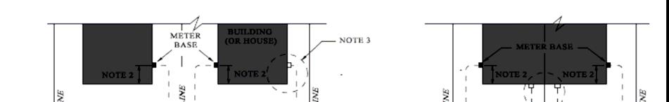
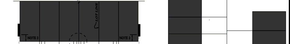
10 Subdivision and Townhome Developments March 2011 All material must conform to the requirements set out in this document including the associated standards, schematics and plan drawings. Any deviation from this must have written approval from BPI, prior to ordering. Material installed, which is not approved by BPI shall be removed and replaced at the Owner's expense. Work on any part of the Electrical Plant shall not commence until all approved material necessary for the completion of that part, has reached and been safely stored at the construction site. The Contractor shall be responsible for the security of all said material on site. The Contractor shall use proper material handling methods and equipment at all times. Where required, BPI will supply, standard locks for equipment enclosures at the Owner's / Contractor s expense. 3.9 SERVICE INSTALLATION AND METERING ON RESIDENTIAL LOTS All new and renewed meter installations for single-family residences including town homes shall be installed outdoors. Meter socket, all service conduit and conductor, load side of the meter socket shall be supplied and installed by the builder in new developments or by the owner of the serviced property in in-fill lots. All service entrance sleeves through the building wall must be a minimum of 300mm (12 ) above finished grade. All external installations shall have a unobstructed clearances as per Ontario Building Code, from the meter or gang meter installations. Meter bases shall be permanently labelled with unit and/or house numbers. No meters shall be installed by BPI on meter bases where the structure is not adequate to provide proper support for the meters or poses unsafe installation conditions for BPI personnel. All meter bases shall generally be located on the same side of the house where the secondary service enters the property line and the following criteria shall be considered: a) If the residence/unit has no garage, then the meter location shall be on the side opposite to the driveway. b) If the residence/unit has a garage and the secondary service enters the property line on the driveway side, then the meter shall be located on the side of the garage. c) Townhouse Development; i. Private Townhomes: For private townhomes, the secondary service shall enter the property line at end of a block of attached townhomes to a ganged metering location, unless otherwise approved by BPI. ii. Freehold Townhomes: For freehold town homes, the secondary service may enter the property line at each individual unit. Where meter bases cannot be installed on the side of garages, a specific location and installation details must be verified from BPI prior to installation. d) BPI standards 25U-202-1, 25U-202-2, 25U and 25U in Appendix A shall act as minimum standards for service layout. 10 of 22
11 Subdivision and Townhome Developments March 2011 NOTE: In situations where a meter base is located on the side of a residence opposite the locations where the secondary service enters the property line, it is the responsibility of the builder to have the secondary service extended or shortened in the common trench to the side of the meter location before service to the property is connected. Service crossing(s) under driveways and across other permanent structures on the property may involve under-digging / over-digging other utilities and shall only be allowed if carried out by qualified contractor and duly inspected and approved by BPI. The services shall be installed in a DB2 conduit of a minimum 100mm (4 ) diameter. Only one secondary splice shall be allowed on any secondary service. Trenching, sand bedding and backfilling from BPI s point of entry at a residential property to the meter base location shall be the responsibility of the owner. The owner shall provide sand bedding in the open trench to a depth of 75mm (3") below the electrical service. The owner shall also provide a stockpile of sand beside the trench for its full length. This sand shall be used by BPI Personnel to place the initial layer of sand over the cable/duct. The sand must be provided as specified prior to the cable being installed. After BPI s Personnel have finished, the owner shall place more sand so that there is a minimum of 150mm (6") of sand over the cable (or duct, as required). All the sand must be placed before the end of the day on which the cable is installed. BPI shall install the cable in the open, clean, dry trench provided by the owner to the line side of the meter socket and inspect and backfill sufficient to temporarily protect the cable. All trenching must be complete, sand bedding ready, and the meter socket and the conduit line side of the socket must be installed before the service conductor will be provided. BPI will assume responsibility for electrical repairs only, of the service conductor up to the line side of the outdoor meter socket, including basic restoration. The owner shall be responsible for excavating, backfilling and restoring surfaces as may be required on private property for future maintenance of the underground service LOCATION OF TRENCHES The main trench, service trench and service lateral shall be located as per Standards , , 25U and 25U All trenching shall conform to CSA Standard C22.3 No. 1 Sections 8, 9 and 10 as a minimum unless specified by BPI LOCATION OF EQUIPMENT The location of transformers, pedestals etc. shall, in general, be in accordance with the Standards and or the site plan as approved by BPI, with the latter having precedence. Any above ground metal structure such as fence, bollards, junction boxes etc., which are located within 1m of a pad-mounted transformer/switch, shall be bonded to the ground grid of that transformer/switch in at least two (02) locations. If the same is located between 1m and 3m of a pad-mounted transformer/switch it shall have its own ground grid complete with ground rods, which shall be continuously bonded with the ground grid of that transformer/switch in at least two (02) locations. A 2/0 bare Copper conductor shall be 11 of 22
12 Subdivision and Townhome Developments March 2011 used to ground and/or bond with the ground grid. Pad-mounted communication pedestals (eg. Bell or Rogers) shall be bonded directly to the ground terminal of BPI pad mounted equipment using grounding cable of appropriate size as per Ontario Electrical Safety Code LOCATION OF ROAD CROSSINGS Road crossings must not terminate under driveways. A minimum clearance of 1m shall be maintained from the edge of driveway to the road crossing. The location of the road crossings with reference to a fixed point (eg. Property line, transformer etc.) must be indicated on construction drawings. Changes to approved crossings or crossings at an angle with respect to the boulevard shall not be carried out without written consent of BPI PRE-ENERGIZATION REQUIREMENT Energization shall be carried out by BPI personnel only. Energization will only be done on the entire phase only, partial energization will not be allowed without prior approval in writing by BPI. Prior to energization of any part or parts of the Electrical Plant and prior to the release of the plan for approval: BPI shall be in receipt of the results of all inspections and tests carried out on the part or parts of the Electrical Plant to be energized, and the results of all such inspections and tests shall be satisfactory to BPI. Unless the Owner is informed otherwise by BPI, The Owner shall be responsible for submitting as-built drawings as per BPI design requirements relating to the construction of the part or parts of the Electrical Plant to be energized. In addition to the above, secondary services to individual lots within the Development, shall not be energized unless: roll-ins or lot-line splices, where required, have been completed by BPI; payment has been received for all fees; service installation including meter base, duct structures etc. have been approved by BPI; meter base connections for that service have been completed; the municipal address is clearly visible on the house; and the service has passed Electrical Safety Authority inspection 3.14 SITE SAFETY All work performed by the Owner through the Consulting Engineer and Contractor shall be in accordance with the most current revisions of the Occupational Health and Safety Act of Ontario and Regulations for Construction Projects. The Consulting Engineer is expected to exert primary controls through his or her line 12 of 22
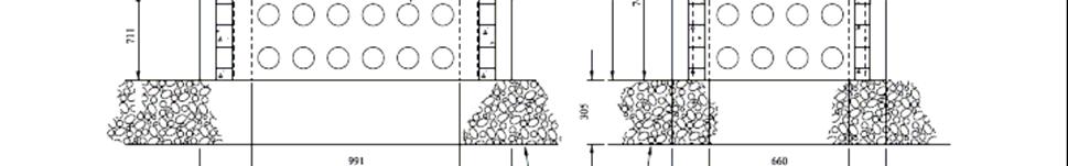
13 Subdivision and Townhome Developments March 2011 supervision to obtain desired performance from employees, contractors, sub-contractors, vendors etc. As a minimum, the following must be implemented: Housekeeping. Orderliness is a basic requirement for all jobs and the job site must be well maintained at all times. Special attention shall be given to maintaining clear walkways and roadways, removal of trash, removal of slipping and tripping hazards, proper storage of material and securing work areas. Prior to energization, on-site Contractor(s) or their designated sub-contractors shall be responsible for the safety of all individuals on their site and shall have proper safety procedures and equipment in place. A copy of this plan shall be forwarded to BPI before commencement of work. After energization of the Electrical Plant in part or whole, BPI shall be responsible for personnel safety on jobs involving handling or operation of live electrical services and shall be contacted before proceeding and to provide the necessary safety equipment for a particular job. Site safety in all other areas shall continue to be the responsibility of the on-site Contractor. Contractors shall use a regular system of work and job site safety inspections to detect, document and correct hazardous conditions, safety violations and unsafe practices WARRANTY PERIOD The Owner shall provide guarantee in the form of a performance bond for all design, construction and installation on the Development. After energization, BPI shall retain 10% of the value of the bond as guarantee for a period of one year, which shall be released upon approval by BPI of the said facilities following a final inspection. If this inspection reveals remedial work that is required from the Owner, BPI shall retain a portion of the above monies as performance warranty equivalent to the cost of the said works, for a period of one year after the completion of this work to the satisfaction of BPI Inspector. 4.0 INSTALLATION OF ELECTRICAL PLANT 4.1 TRENCH EXCAVATIONS AND BACKFILLING Trench shall be excavated to sufficient depth to accommodate the designed number of ducts and cables. The Contractor shall note that in some areas underground sewer mains and services, storm drains, telephone or communications cables, gas lines, and other below ground utilities may exist in close proximity to the work. Excavation around other utilities, pipes, culverts, and similar installations shall be done with extreme care in accordance with the latest edition of Ontario Health and Safety Act. It shall be the Contractor's responsibility to contact the Customer/operator of each utility encountered, and obtain information relative to location and depth before excavating in the area. In the event of a conflict with the location of work, the encountered utilities shall not be disturbed before approval is obtained from the utility s owner. Private utilities encountered shall be brought to the attention of BPI inspector. The Contractor shall promptly notify the utility concerned in the event of damage occurred during construction, whether caused by 13 of 22
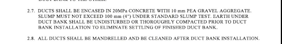
14 Subdivision and Townhome Developments March 2011 him/her or others. Locations where minimum separation between gas pipelines and the standard trench fall below 380mm (15") shall be immediately brought to the attention of the BPI inspector. Primary and secondary cable runs in a trench shall have 75mm (3") of sand below and 150mm (8") of sand above all direct buried cables/ducts, before regular backfill. The sand used shall have no smooth stone over 13mm (1/2") diameter and no crushed stone. The trench bottom shall be kept as smooth as possible to permit laying of cable or duct. If in the opinion of the inspector, any part of the bottom of the trench is found unsound or in any way unsuitable, the Contractor shall remove as much as may be required and replace accordingly. 4.2 JOINT USE OF TRENCH Unless otherwise approved by BPI, electric utility power cables shall not be placed in the same trench as Bell Canada and Cable Television facilities. If joint-use is approved by BPI, the Electrical Consulting Engineer shall arrange coordination and provision of joint-use plans. Reasonably adequate time shall be provided for Bell Canada and Cable Television to prepare for the installation of their plant. A minimum vertical separation of 300mm (12") shall be maintained between BPI cables, and Bell Canada, Rogers and other communication cables together with a red warning tape on top of BPI cables along the entire length of the joint use (see Section 4.7). Sand must be used for backfill over BPI cables. Above grade telephone and cable facilities shall be located so as not to conflict with above grade BPI facilities. Pedestals shall be placed clear of transformers so as not to interfere with access to the cable compartment. All pedestals placed within 1m. of transformers shall be effectively bonded to the transformer system ground. 4.3 CONCRETE FOR FOUNDATIONS AND DUCTS Concrete shall be poured in place or pre-cast in accordance with BPI standard details. Poured in place sections shall be constructed by pouring concrete between the fitting and the undisturbed wall of the trench. Care shall be exercised to ensure that the concrete is clear of joint accessories, bolts, nuts etc. Concrete shall be composed of Portland cement, water, 10mm pea gravel aggregate and an air-entraining, low-slump mixture. Accelerating or anti-freeze admixtures will not be permitted. No above-grade pour shall be allowed when forecasted ambient temperature is above 25 0 C or below 5 0 C within 72hours of the pour-in. Below-grade poured concrete shall be provided with adequate coverage to protect against thermal damage. Cement shall be of Type II confirming to ASTM Cl50. Preferably, water used in mixing and curing concrete shall be potable (heated and cooled seasonally). Non-potable water shall be fresh, clean and free from injurious amounts of sewage, oil, acid, alkali, salt, or organic 14 of 22
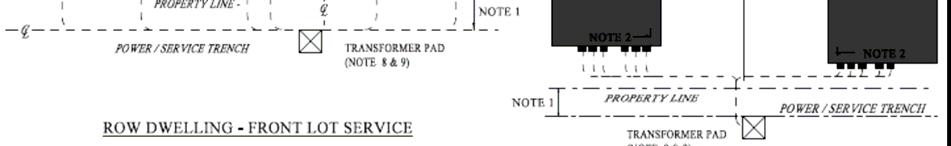
15 Subdivision and Townhome Developments March 2011 matter. Air entraining admixtures shall conform to the Specifications for Air Entraining Admixtures for Concrete (ASTM C260). Unless otherwise shown on approved design, concrete used for load bearing foundations (such as pad mounted transformer, switches, junction/pull boxes etc.) shall have a 28-day minimum compressive strength of 31 MPa. Vaults shall be pre-cast with smooth-finish tops formed with a #3 Hi-bond reinforcing steel rebar design (minimum diameter of 3/8, centred at 6 in both directions to cover the entire area) and tested for heavy wheel loading. Concrete encased duct banks shall be reinforced with non pre-stressed 15mm (5/8 ) deformed steel reinforcing bars grade 400 and conforming to CSA G30.12 (latest revision). Steel reinforcing bars shall be installed continuously; minimum 300mm overlap, tied with non-metallic ties and be located as per Standards to Concrete shall have a 28-day compressive strength of 20 MPa or more without rebar. Duct openings in concrete structures shall be flared and recessed with poly-seals. BPI shall determine if concrete testing is necessary and shall also determine the method of any concrete testing which is performed. The slump of concrete for foundations shall be the minimum that is practicable such that the concrete may be easily shaped into the desired form. Segregation of materials in the mixture shall not be permitted. When poured in place on site, forming, and placing of concrete may be inspected and shall be subject to approval by BPI. Curing and form removal for concrete sections, and requirements due to air temperature and weather conditions shall follow proper construction practices and shall be subject to approval by BPI. 4.4 INSTALLATION OF DUCTS All duct material and the associated fittings used for the construction of the Electrical Plant shall conform to CSA standard C.22-2 No MI 984 and subject to BPI approval. For above-grade installation, Rigid-PVC conduits, risers and bends (Schedule 40) shall be used. The duct(s) shall be laid end-to-end in as straight a line as possible to facilitate pulling in of the cable. Maximum number and radii of bends between pull points (i.e. manholes, hand holes, transformer bases/vaults etc.) shall be based on pull calculations. Where three (03) or more ducts are installed in one trench they must be concrete encased. "3M" EMS markers shall be installed at the termination point of all spare ducts and the ends of road crossing ducts. Where tie-ins are made to ducts left for future plant these ducts shall be continued to the next structure except where left for services. These shall be properly sealed using an approved duct seal once services are installed to prevent migration of silt. All ducts that are to terminate within a structure must terminate with a bell end placed flush with the inside wall of the structure. Where these ducts enter the vault care should be taken to maintain a seal that will not allow sediment into the structure. All direct buried cables (other than grounding cables) entering in to a structure must enter through a 1.5m minimum length of duct with a bell end also at the trench end of the duct. 15 of 22
16 Subdivision and Townhome Developments March 2011 This end shall be sealed around the conductors using an approved duct seal. Grounding/bonding cables shall enter the structure through the lifting holes, if available and an approved seal shall be made around these to prevent silt migration. A continuous 10mm (3/8 ) dia. polypropylene pull rope must be installed throughout the entire length of all spare ducts. This rope is to be tied off within the structure wherever possible, at the discretion of BPI Inspector. Following usage makes the installation of ducts mandatory by the Contractor: a) On all road allowances where the cables pass under travelled roadways, they shall be in ducts, which shall be concrete encased. b) Primary voltage cables installed direct buried shall have a spare duct installed in parallel for the buried length for exclusive use by BPI. This duct shall be installed direct buried in boulevards and concrete encased at road crossings and bends around corners in the boulevard. Only one spare duct is required per length, for either single phase or three phase installation c) In addition to above, spare ducts shall also be installed to provide future servicing to blocks of land and future extensions to the Development. d) On all service risers and crossings underneath aboveground structures DIRECT BURIED INSTALLATION Where ducts are installed direct buried, the excavation shall be carried out so that all ducts are supported on a solid bed of undisturbed earth. Ducts, which are terminated in soil, shall be plugged with plastic caps, the exact location noted on the plan and a 3M marker placed at the location. The duct lengths shall be joined together with approved couplings of the same make and bonded with PVC glue. Where two ducts are installed direct buried in a trench, each duct shall be separated from the other by at least 75mm (3"). The ends of all buried ducts and any change in the direction of the ducts shall be tied down in the field and shown on the As-Built plans. Ducts shall be terminated at poles as per Standard in Appendix A CONCRETE ENCASED INSTALLATION All concrete-encased duct banks shall be designed and installed as per Standard and Ducts shall be terminated at poles as per Standard Ducts shall be concrete encased around daylight corners and all other tight radii turns as per Standard INSTALLATION CAPACITY The number of ducts required in a concrete envelope or to provide service to future Development will depend on the cables to be installed in them. The maximum number 16 of 22
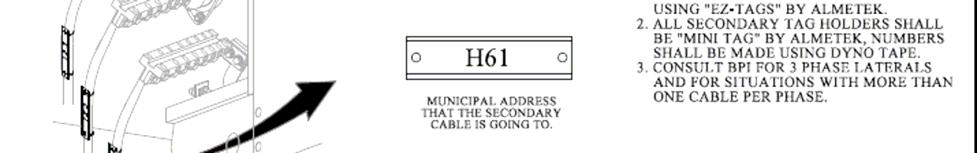
17 Subdivision and Townhome Developments March 2011 of cables in each duct shall not exceed the maximum allowable fill capacity as per the current applicable CSA standards. Different voltage cables, with the exception of grounding cable, shall not be installed in the same duct. 4.5 ROAD CROSSINGS Concrete envelopes under roadways must extend at least 300mm (1') beyond the proposed curbs and be a minimum 760mm (30") below proposed boulevard grade. In all cases, the concrete envelope below the roadway must be at a minimum depth of 1000mm (40 ). The duct ends must terminate at the main trench. Concrete road crossings shall be perpendicular to the road alignment and where possible placed across from the transformer or switch pads and the ducts carrying utility cables shall extend and terminate into the vault. All other services ducts (eg. Bell, cable etc.) shall terminate before the vault, or be routed around it. Refer to Standard in Appendix A for road crossing details. Where crossings terminate at a structure (vault, etc) the structure shall be placed first and the crossing shall be poured against the wall of the structure to the other side of the street. 4.6 CABLE INSTALLATION The Contractor will use care in storing, handling and installing the cables to prevent scuffing or otherwise damaging the protective covering. Cables shall generally be installed direct buried unless otherwise noted on the plans or as directed by BPI. All direct buried cables in a common trench on private property and street allowance shall be separated from adjacent cables of the same voltage class and supported at the bottom using sand bedding with minimum depth of 75mm (3 ) and a sand cover of 200mm (8 ) above. The exact location of any mid-span splicing or termination shall be noted on the plan and a 3M marker placed at the location, 300mm below grade. All cable ends shall be properly capped with a bonding cement and PVC cap or taped and identified at each termination location. The cables will be handled and reeled off in such a manner as to prevent kinking or bending beyond the minimum radius. The conductor shall be laid as straight as possible. Crossover of cable shall be permitted only at service entrances. Cables shall be trained into ducts with bell-end terminations in smooth bends and looped to a length generally equal to the vault perimeter, which shall be left inside the vault for connection INSTALLATION OF SECONDARY CABLES Secondary cables shall be labelled with the house numbers, which the cables services as per Standard Each dwelling unit on a single-family or semi-detached lot shall have its own individual service cable from the transformer to the meter base and shall be sized to 17 of 22
18 Subdivision and Townhome Developments March 2011 suit in accordance with the cable specification of Appendix-D. For service installation on private residential lots and meter base, refer to Section TERMINATION AND CONNECTION OF SECONDARY CABLES Cables shall be looped or snaked at termination point with sufficient cable left to ensure ease of installation. Secondary connections at transformer shall be made using connectors as specified in Appendix E. Secondary neutral cables only shall be connected to transformer by the Contractor prior to hi-pot testing. The Contractor shall also make connections for secondary service at the meter base unless the installation is done by BPI. Secondary connections (other than neutral) at the transformer shall be made by BPI. Where cables are left unconnected or exposed, they shall be capped with bonding cement and PVC cap, or if approved, sealed, with rubber tape and made waterproof as follows: a) The first layer shall consist of two (02) wraps of self-amalgamating tape, half lapped to provide the necessary electrical characteristics for 600V and sealed against ingress of moisture. b) The second layer shall consist of two (02) wraps of vinyl tape and shall be applied half lapped to enclose the first layer of tape. It shall be made and installed in a manner to eliminate unravelling (i.e. last two lengths of wraps around the circumference of the cable, are not to be stretched) INSTALLATION OF PRIMARY CABLES Primary cable shall be 1/0 AWG and as per specification in Appendix D. No splice shall be allowed in the primary cables. Primary cables shall be labelled as per Standard Primary cables shall generally be installed at the bottom of and in the same trench as the secondary cables. There shall be a minimum separation of 150mm (6 ) between the primary and the secondary cables. For primary cable installation at the dip pole refer to Standard TERMINATION OF PRIMARY CABLES Primary cables shall generally be connected by BPI, however, the Contractor shall be responsible to prepare cables terminations for final connection. Only trained electricians or linepersons experienced in primary cable terminations and approved by BPI shall install primary terminations. A list of approved cable terminations for primary cable is included in Appendix E. The primary cables shall be terminated with BPI approved 200 Amp load break elbows. The load break elbows may be left on de-energized transformer bushings to aid in storage of elbows. Protection of the local service primary loop ends shall be by RTE elbow surge protectors, if required, and placed as shown on the approved schematic. 18 of 22
19 Subdivision and Townhome Developments March 2011 High voltage dead-end caps, plugs, standoff bushings shall be as specified in the list of approved materials in Appendix E. All pole-top cable terminations shall be supplied and installed by the Owner/Contractor, for connection by BPI. The conductor shall be terminated with either a pin-type or a two-hole lug, as per BPI standard detail on the primary schematic. Overhead switches and phase terminations shall be identified as required by BPI. Loops fed directly from overhead lines shall be protected with a Surge Protector at the stress cone of the riser pole. For underground terminations, a fault indicator (Catalog # STHI in Appendix E) shall be installed on the test point of the load side load break elbow at each transformer, switch or junction location other than at a normally open point. For overhead terminations, with a line tap switch, BPI shall supply and install a fault indicator (Catalog # SDHI2 in Appendix E) on the source termination conductor feeding the subdivision TESTING The Owner shall complete all of the Electrical Plant prior to requesting testing and energization. Upon completion of all terminations and grounding, and with Contractor and BPI personnel present, the following tests must be performed. a) All cables shall be meggered and identified to verify the correctness of cable tags. Primary cables shall be submitted to a standard Hi-pot test and the standard test form in Appendix F shall be completed and submitted to BPI Inspector. Each primary cable shall be tested continuously for a period of 15 minutes. The test shall start at 25 KV for the first 5 minutes, then 50 KV for another 5 minutes, then 75KV for the final 5 minutes. All tests must be done in dry conditions. Acceptance of the tested cables shall be subject to approval by BPI inspector. Cables, whose test results are not satisfactory to BPI or have not been witnessed by BPI Inspector, shall be replaced with new ones and retested at no extra cost. No re-testing of tested cables shall be allowed INSTATALLATION OF NEUTRAL The Contractor shall install the secondary neutral wire at the transformer including all terminations. Concentric neutrals shall be bound and terminated as per termination manufacturer s recommendations. 4.7 WARNING TAPE / ELECTRONIC MARKER It is required to install an electronic marker (3M s #1256 Power), a warning tape or a 19 of 22
20 Subdivision and Townhome Developments March 2011 concrete over-lay as specified at the following locations. The tape or marker shall be installed 300mm below finished grade in all trenches. The tape shall be bright RED coloured plastic on polyethylene, 75mm -152mm wide with inscription CAUTION BURIED ELECTRIC CABLES BELOW. Where sufficient cover above the cables, of a standard trench, is not possible, mechanical protection shall also be provided by using cable bricks or concrete cover. The Contractor shall bring in and stub the secondary service cable at least 1m inside the property line with at least 3m (10 ) of cable coil left for future splicing, as shown in Standard 25U The coiled cable end shall be buried in clean sand and an EMS cable marker shall be place on top. Marker at all duct ends; Marker at splice locations (primary and secondary); Marker where there are buried cable coils; Tape over concrete over-lay (bricks or slabs) where there are non-standard cable depths; and Marker/tape with or without concrete overlay at any other area specified by BPI inspector. 4.8 INSTALLATION OF SYSTEM GROUND At each transformer, switchgear and cable termination, the case and all other non-current carrying metallic parts shall be grounded. Grounding conductors of other utilities in the area shall be bonded to the utility system ground. Grounding at all primary voltage equipment shall consist of four (04), 19mm (3/4") diameter by 3m (10') long copper clad steel ground rods, figure-8 or C type copper compression connectors, and sufficient 2/0 AWG bare copper conductor to completely encircle the equipment vault or manhole with a clearance of 1m, and connect the ground rods to the equipment ground bushings, as per Standard 41U-200 in Appendix A. Additional grounding provisions may be required if rock is encountered. An insulated ground line shall be installed from the ground grid at the transformer to the meter bases as per Standard 41U-300 in Appendix A. 4.9 INSTALLATION OF TRANSFORMERS Single-phase transformers shall be used for the supply of power to residential homes and townhouses and shall be as specified in Appendix C. Transformers shall be selected to comply with the minimum requirements set out in the latest edition of CAN/CSA - C for transformer losses and CAN/CSA for minimum efficiency values. The minimum impedance for 50kVA transformers shall be 1.5% and for 100kVA transformers, shall be 2.5%. Notwithstanding the above, all type test reports or third party inspection reports shall be made available to BPI for review and acceptance prior to installation. Pad mounted transformers shall be numbered with BPI-designated transformer numbers painted on the sides and visible from road. 20 of 22
21 Subdivision and Townhome Developments March TRANSFORMER LOCATION The transformer shall be located as close as possible to the load center. The clearances to building and property lines shall be selected to achieve the necessary space separation for oil-insulated transformers installed outdoors in accordance with electrical safety code and standards. The Electrical Consulting Engineer must select locations that are not in line with drainage swales or sufficient lot grading must be done to redirect water flow away from transformer vaults. The transformer vaults shall be located as shown on the plan view drawing of the Electrical Plant and in general, positioned on the lots in the locations shown on Standard and in Appendix A TRANSFORMER VAULTS Vaults shall be set to provide for a minimum 50mm (2 ) -150mm (6") clearance from top surface to finished grade. The earth beneath the foundation shall be un-disturbed or well tamped. Smooth clear stone of size 19mm (3/4 ) shall be laid to a depth of 300mm (1 ) under the entire structure and shall extend 200mm (8 ) beyond the outer walls of the concrete vault. The grade of the area surrounding the vault shall be sloped in such a manner that run-off is directed away from the vault. The earth material around the vault shall be prepared and maintained to prevent formation of sinkholes. The concrete vaults shall be constructed as per standard in Appendix A and be complete with steel plate and plate locking bolts. The installation of the transformer vaults shall be inspected by BPI Inspector prior to the Contractor committing any ducts or cables to them ORIENTATION AND PLACEMENT The transformers shall be mounted on concrete vaults and oriented so that the transformer opening is opposite to the direction of traffic flow and parallel to the road for ease of operation and maintenance. In the case of poured-in concrete vaults, placement of the transformer on vaults shall not be made before the poured-in foundations have reached full strength, which shall not be less than 7 days in all circumstances. A Consultant certificate verifying the designed load capacity of the vault shall be submitted to BPI, duly signed and stamped by a Professional Engineer. Any damage to the transformer after placement, as a result of this shall be the responsibility of the Developer or contractor and may delay energization of service by BPI. The transformer shall be left at all times with all penta-bolts tightened down INSTALLATION OF SWITCHGEAR Some subdivisions may require the installation of switchgear. The Owner shall purchase the switchgear and install it to the most current BPI specifications and standards. The specifications and standards will be provided at the time switchgear is required. 21 of 22
22 Subdivision and Townhome Developments March 2011 Installation of switchgear foundation and placement shall follow the same standards as required for transformers. The owner shall confirm that the dimensions and weight of the switchgear matches the foundation footprint and its load bearing capacity before placing the order. Vault catalog number (if available) and dimensions shall be provided on the plan view drawing INSTALLATION OF PRIMARY DIP POLE(S) Where primary dip poles are installed by the Owner s contractor, the pole design must be approved and stamped by a P.Eng. certified to meet the safety requirements of Ontario Regulation 22/04. All poles receiving BPI overhead primary service wires shall be rated Class-3 or higher and all unbalanced loads on the pole, supported with adequate number of guys and anchors. The installation shall be subject to BPI inspection and approval. 22 of 22
23 APPENDIX A DRAWINGS SHOWING STANDARD INSTALLATION PRACTICES
24
25
26

27
28
29
30
31
32

33


34
35
36
37
38
39
40
41
42

43
44
45
46
47
48 APPENDIX B DRAWINGS SHOWING STANDARD DRAFTING PRACTICES
49
50
51
52
53
54 APPENDIX C TRANSFORMER SPECIFICATIONS
55 16 kv LOW PROFILE SINGLE PHASE, DEAD-FRONT, PAD-MOUNTED DISTRIBUTION TRANSFORMER SCOPE This specification is for a single phase mini-pad mounted oil filled distribution transformer rated 50 to 167 kva in the 18 kv insulation class with 125 kv BIL and oil immersed primary switch and fuse protection. STANDARDS APPLICATION Canadian Standards Association (CSA): Z299 Canadian Standards Association (CSA): C Canadian Standards Association (CSA): C M 1979 Ansi: Separable Insulated Connectors: Transformer capacity and voltage class shall be specified on the request for quotation. 2. Clause 3.2 of CSA C2 shall be replaced by the following: * the winding insulation shall be 65 degrees C Class, but the nameplate kva rating shall be based on a temperature rise of 55 degrees C. PRIMARY PROTECTION The primary windings shall be protected by a removable oil immersed load break bay-onet expulsion fuse. Fuse shall be correctly rated and co-ordinated to the rating of the transformer. The owner shall also supply the manufacturer's co-ordination data to the BPI Engineer for evaluation with the tender submission. H.V. TERMINALS 1. Units are to be equipped with two 200 Amp high voltage bushing wells per phase meeting the requirements of ANSI/IEEE Standard The two HV bushings shall be joined by an internal bus capable of carrying 200 amperes and braced to withstand fault currents to 10,000 Amps symmetrical. 2. The high voltage bushing wells shall be in the standard arrangement used for feed through transformers as specified in C M The tank wall shall be fitted with a parking stand for each phase suitable for parking load break stand off plugs. LOAD BREAK SWITCH Each transformer shall be equipped with a load break switch on the High Voltage side
56 capable of isolating all primary fusing, the transformer winding and secondary side from the High Voltage feed through. The feeder connections shall be clearly marked on the transformer and a clear indication of the switch position shall be incorporated into the switch handle. The primary switch shall be an RTE, load break sectionalizing switch rated 35 kv, 200 A and braced to withstand fault currents of 10,000 Amps symmetrical. L.V. TERMINALS Secondary epoxy bushings shall be supplied with drilled bar type terminals shown in Figure 5 of CSA C227.3-M1979, suitable for copper or aluminium terminations. A strap shall interconnect externally the LV neutral bushing and external ground lug. TAP CHANGER Tap changer shall be located in the high voltage compartment and four taps shall be provided at 2 1/2%, two above and two below normal voltage. GROUNDING Primary shall be solidly grounded to the transformer tank at the same spot on the tank as the external ground. Otherwise, all grounding requirements shall be in accordance with the CSA Standard C LOSS FORMULA The final decision for selection of manufacturer and award of quotation will be made using the loss formula 5N + 2L. COMPARTMENT Cable compartment shall be fitted with hinged doors which when closed and locked make the unit completely tamper proof. IDENTIFICATION AND MARKING The nameplate and connection diagram (combination plate) shall be located in the LV compartment and be of material and construction which will withstand weathering and repeated cleaning. The connection diagram shall include a plan view of the bushing configuration and corresponding bushing designation. A 2 digit date of manufacturer, e.g. "82" shall be stamped on the nameplate in any convenient location. A separate data block is not a requirement. It must be clearly indicated on the nameplate that the oil contained in the transformer is P.C.B. free. INFORMATION TO BE SUBMITTED The Owner shall submit to BPI, two copies of an outline drawing of the transformer.
57 APPROVED TRANSFORMER MANUFACTURERS Carte Electric Limited Federal Pioneer Ferranti-Packard Transformers Inc. Moloney Electric Corporation CAM Tran Co. ASEA Brown Boveri Inc.
58 APPENDIX D PRIMARY AND SECONDARY CABLE SPECIFICATIONS
59 GENERAL SPECIFICATION FOR CONCENTRIC NEUTRAL POWER CABLE 28 KV 1) SCOPE This specification covers the requirements for 28 KV concentric neutral power cable. 2) STANDARDS All insulated power cable manufactured under this specification will conform to standards of materials, construction and testing as required by the latest revision of IPCEA Standard S and CSA Standard C ) OPERATING CONDITIONS Power cable manufactured under this specification shall be capable of continuous operation at 60 cycle A.C. at 90 o C at voltage as specified and must be suitable for installation at minus 40 o C and must be suitable for operation direct buried, in underground duct or exposed to ambient air in direct sunlight in wet or dry locations. 4) CABLE CONSTRUCTION Conductor: Strand Shield: Insulation: Annealed uncoated compressed strand copper Extruded semi-conducting cross linked Cross-linked polyethylene Insulation Shield: Semi-conducting polyethylene or cross-linked polyethylene Concentric Neutral: Jacket: Annealed copper wires, full capacity Polyvinyl chloride 5) TESTING Completed cable test reports shall be submitted to BPI prior to shipment.
60 GENERAL SPECIFICATION FOR DIRECT BURIED SECONDARY CABLE 1. SCOPE This specification covers the requirements for direct burial secondary cable for 600 Volt underground distribution system. 2. STANDARDS All cable manufactured under this specification will conform to standards of materials, construction and testing as required by CEA Specifications WCW-04 USC 90, except as modified by this specification. 3. CONSTRUCTION The finished cable shall consist of one, two or three (as required) insulated and jacketed conductors. Two and three conductor cables shall be twisted with a righthand lay not less than 25 and not more than 60 times the diameter of the finished cable. Three conductor cable shall be reduced neutral as per table COLOUR CODE The two phase conductor shall be coloured black and red and the neutral conductor shall be coloured white. Cable Sizes to be Triplexed Phase (2 conductors) Neutral (1 conductor) 2 AWG 4 AWG 1/0 AWG 2 AWG 3/0 AWG 1/0 AWG 250 AWG 3/0 AWG 500 AWG 250 AWG
61 APPENDIX E CATALOG NUMBERS OF APPROVED EQUIPMENT
62 EQUIPMENT MANUFACTURER CAT NO. Loadbreak Elbow with Test Point Cooper/RTE PLE228F06TC Bushing Well Insert Cooper/RTE LBI228 Feedthru Insert Cooper/RTE LFI228 Portable Feedthru Cooper/RTE C-01-MC Loadbreak 2-way Junction Cooper/RTE B-01-MG Loadbreak 3-way Junction Cooper/RTE B-02-MG Loadbreak 4-way Junction Cooper/RTE B-03-MG Insulated Stand Off Bushing Cooper/RTE ISB228 Protective Cap Cooper/RTE PLPC228 Splice 3M 5421-CI1/0A TPR Fault Indicator with Cooper/RTE STHI 800 Amp Trip Rating Overhead Fault Indicator Cooper/RTE SDHI2 Cold Shrink 0/H Cable 3M 5646 Termination Kit Elbow Type Lightning Arrestor Cooper/RTE C21-M Secondary Connector Utilco TUT KV 100 Amp ABB 279C790A23 Load Break Cutout O/H Lightning Arrestor 21 KV Ohio Brass ETP40 Sure-Guard 0/H Current Limiting Fuse 40 K General Electric 9F59UBD134 EMS Marker 3M 1256 NOTE: Elbow and splices are sized for use with 1/0 compact cable with insulation diameter of inches.
63 APPENDIX F CABLE HIGH POTENTIAL TEST

64 CABLE HIGH POTENTIAL TEST LOCATION: CABLE MFG. INS. TYPE: RATED VOLTAGE: SIZE: LENGTH: TIME OF DAY: TEMPERATURE: WEATHER CONDITIONS: DESCRIPTION OF ROUTE FOR CABLE UNDER TEST: o C Test Voltage Leakage Current in Microamps 1 Min 2 Min 3 Min 4 Min 5 Min 25 kv DC 50 kv DC 75 kv DC COMMENTS: TEST INSTRUMENT USED: TESTED BY: BRANTFORD POWER WITNESS: DATE:
Section 2: Underground
 Section 2: Underground GENERAL INSTALLATION REQUIREMENTS FOR UNDERGROUND FACILITIES Underground electric service and meter location will be established by NHEC upon site visit. In some instances the type,
UNDERGROUND SERVICES - GENERAL SERVICE AND MULTI-UNIT RESIDENTIAL
 UNDERGROUND SERVICES - GENERAL SERVICE AND MULTI-UNIT RESIDENTIAL 8.01 GENERAL This material is not intended to cover service from OPPD s network in the downtown Omaha area. See Chapter 12 for details
Contact Clark Public Utilities Construction Services department at (360) to initiate a request for service.
 to initiate a request for service.") CHAPTER3 Clark Public Utilities Commercial Electric Service Handbook Commercial Underground Services Preparing for the installation The following checklist will assist in preparing a project for the installation
CHAPTER3 Clark Public Utilities Commercial Electric Service Handbook Commercial Underground Services Preparing for the installation The following checklist will assist in preparing a project for the installation
TS 803 DUCTS DUCT INSTALLATION, PROTECTION AND MARKING WITHIN A TRENCH OPEN TRENCH DUCT INSTALLATION PROFILE
 TORONTO TRANSPORTATION March 2012 TS 803 DUCTS TABLE OF CONTENTS 1. DRAWINGS TTD 803.001 TTD 803.010 DUCT INSTALLATION, PROTECTION AND MARKING WITHIN A TRENCH OPEN TRENCH DUCT INSTALLATION PROFILE 2. CONSTRUCTION
SPECIAL SPECIFICATION 6664 Level (3) Communications System
 Communications System") 2004 Specifications CSJ 1200-05-014 SPECIAL SPECIFICATION 6664 Level (3) Communications System 1. Description. A. This Item will govern the installation of all facilities belonging to Level (3) Communications,
2004 Specifications CSJ 1200-05-014 SPECIAL SPECIFICATION 6664 Level (3) Communications System 1. Description. A. This Item will govern the installation of all facilities belonging to Level (3) Communications,
SPECIAL SPECIFICATION 6658 Time Warner Communications System
 2004 Specifications CSJ 1200-05-014 1. Description. SPECIAL SPECIFICATION 6658 Time Warner Communications System A. This Item will govern the installation of all facilities belonging to Time Warner Cable
[Type text] Heber Light & Power. Developers & Excavators. Electrical Service Requirements Manual
![[Type text] Heber Light & Power. Developers & Excavators. Electrical Service Requirements Manual](/thumbs/83/87082261.jpg "[Type text] Heber Light & Power. Developers & Excavators. Electrical Service Requirements Manual") [Type text] Heber Light & Power Developers & Excavators Electrical Service Requirements Manual May 2017 E.1.1 - GENERAL REQUIREMENTS PURPOSE This section was prepared to aid developers, contractors, engineers
[Type text] Heber Light & Power Developers & Excavators Electrical Service Requirements Manual May 2017 E.1.1 - GENERAL REQUIREMENTS PURPOSE This section was prepared to aid developers, contractors, engineers
Underground Residential Distribution (Specifications for Installation) PES March 2008 Spec 11
 PES March 2008 Spec 11") Underground Residential Distribution (Specifications for Installation) PES March 2008 Spec 11 Underground Residential Distribution (URD) Index General Discussion... 1-2 Description... 3-7 Drawings (Available
Underground Residential Distribution (Specifications for Installation) PES March 2008 Spec 11 Underground Residential Distribution (URD) Index General Discussion... 1-2 Description... 3-7 Drawings (Available
Please check with your local inspection authority for any additional requirements before installation.
 Specifications for Residential Underground Electric Service Installation This brochure addresses most typical residential underground service installations. Variances for the following specifications must
Merrimac Municipal Light Department. Commercial Developments Policy
 Merrimac Municipal Light Department Commercial Developments Policy General: This document provides specific instructions for the provision of underground electrical facilities associated with the construction
ELECTRICAL SAFETY Information Bulletin
 ELECTRICAL SAFETY Information Bulletin February 2019 Page 1 of 5 2018 CANADIAN ELECTRICAL CODE SUBJECT: Section 6 Services and service equipment Rule 6-102 Number of supply services permitted Row housing
CONSTRUCTION SPECIFICATION FOR GROUNDING
 ONTARIO PROVINCIAL STANDARD SPECIFICATION METRIC OPSS 609 NOVEMBER 2001 CONSTRUCTION SPECIFICATION FOR GROUNDING TABLE OF CONTENTS 609.01 SCOPE 609.02 REFERENCES 609.03 DEFINITIONS - Not Used 609.04 DESIGN
400 watt, high pressure sodium. Type C watt, high pressure sodium Collector Street Light Units
 CITY OF MEDFORD PUBLIC WORKS DEPARTMENT ENGINEERING & DEVELOPMENT DIVISION TRAFFIC ENGINEERING SECTION April 15, 2010 Street Lighting Standards and Specifications Luminaire Types Type R-100 100 watt, high
Basic Service. This Section provides information regarding a. Introduction
 Basic Service Introduction This Section provides information regarding a new electric Basic Service for a single phase service less than or equal to 400 amps, and a three phase service less than 50kW.
SECTION UNDERGROUND ELECTRICAL CONSTRUCTION
 PART 1 - GENERAL 1.1 DESCRIPTION SECTION 26 05 41 UNDERGROUND ELECTRICAL CONSTRUCTION A. This section specifies the furnishing, installation, and connection of precast manholes and pullboxes with ducts
Section 7: Specifications
 Section 7: Specifications 29 31 Building Boundary of Clear Area See Note # 1 8' Shrubs 8' Concrete Pad Equipment 8' TRAVELED WAY M Meter Pedestal 8' Curb Protective Vehicle Posts (Bollards) If Required
CHAPTER 11 CONDUITS AND FITTINGS
 CONDUITS AND FITTINGS CHAPTER 11 CONDUITS AND FITTINGS The standards and requirements for conduits and fittings used for traffic control signal and lighting systems are presented in this chapter. 11.1
CONSTRUCTION SPECIFICATION FOR INSTALLATION OF ELECTRICAL CHAMBERS
 ONTARIO PROVINCIAL STANDARD SPECIFICATION OPSS.PROV 602 NOVEMBER 2017 CONSTRUCTION SPECIFICATION FOR INSTALLATION OF ELECTRICAL CHAMBERS TABLE OF CONTENTS 602.01 SCOPE 602.02 REFERENCES 602.03 DEFINITIONS
Specifications for Electrical Underground Residential Distribution Systems
 Specifications for Electrical Underground Residential Distribution Systems Specification DDS-2 Revision 13, February 2010 ONCOR ELECTRIC DELIVERY COMPANY SPECIFICATIONS FOR ELECTRICAL UNDERGROUND RESIDENTIAL
CONDUITS AND FITTINGS
 CONDUIT AND FITTINGS Rigid Steel Conduit 3801 Rigid PVC Conduit 3803 HDPE Conduit 3803 Flexible Non Metallic Liquid Tight Conduit Type LFNC-B 3804 PVC Coated Urethane Lined Galvanized Rigid Steel Conduit
CONSTRUCTION SPECIFICATION FOR THE INSTALLATION OF ELECTRICAL CHAMBER
 ONTARIO PROVINCIAL STANDARD SPECIFICATION METRIC OPSS 602 MARCH 1993 CONSTRUCTION SPECIFICATION FOR THE INSTALLATION OF ELECTRICAL CHAMBER 602.01 SCOPE 602.02 REFERENCES 602.05 MATERIALS TABLE OF CONTENTS
SECTION GROUNDING AND BONDING FOR ELECTRONIC SAFETY AND SECURITY
 PART 1 - GENERAL 1.1 DESCRIPTION SECTION 28 05 26 GROUNDING AND BONDING FOR ELECTRONIC SAFETY AND SECURITY SPEC WRITER NOTE: Delete // // if not applicable to project. Also delete any other item or paragraph
CONSTRUCTION SPECIFICATION FOR FOOTINGS AND PADS FOR ELECTRICAL EQUIPMENT
 ONTARIO PROVINCIAL STANDARD SPECIFICATION OPSS.MUNI 616 APRIL 2018 CONSTRUCTION SPECIFICATION FOR FOOTINGS AND PADS FOR ELECTRICAL EQUIPMENT TABLE OF CONTENTS 616.01 SCOPE 616.02 REFERENCES 616.03 DEFINITIONS
CONSTRUCTION SPECIFICATION FOR FOOTINGS AND PADS FOR ELECTRICAL EQUIPMENT
 ONTARIO PROVINCIAL STANDARD SPECIFICATION METRIC OPSS 616 NOVEMBER 2008 CONSTRUCTION SPECIFICATION FOR FOOTINGS AND PADS FOR ELECTRICAL EQUIPMENT TABLE OF CONTENTS 616.01 SCOPE 616.02 REFERENCES 616.03
CONSTRUCTION SPECIFICATION FOR CABLE INSTALLATION
 ONTARIO PROVINCIAL STANDARD SPECIFICATION METRIC OPSS 604 NOVEMBER 2004 CONSTRUCTION SPECIFICATION FOR CABLE INSTALLATION TABLE OF CONTENTS 604.01 SCOPE 604.02 REFERENCES 604.03 DEFINITIONS - Not Used
Underground Service Requirements and Instructions
 This packet includes all FKEC underground service requirements, instructions, procedures and drawings. If you are considering underground power service please review this document in its entirety (3 page
CITY OF UNION, OREGON TECHNICAL SPECIFICATIONS SECTION 9 UNDERGROUND UTILITIES
 A. GENERAL 1. Scope. These specifications cover the installation of the utility systems and appurtenances for the electrical power, telephone, gas, and television as shown in the Drawings. The Work includes,
Huntsville Utilities Underground Residential Service Requirements
 Huntsville Utilities Underground Residential Service Requirements Sections: Scope General Conduit Installation Conduit Termination at Riser Pole Conduit Termination at Padmount Transformer or Secondary
A. Product Data: For surface pathways, wireways and fittings, floor boxes, hinged-cover enclosures, and cabinets.
 ALLIANT ENERGY CENTER PAVILIONS Project No. 2013 027 SECTION 27 05 28 - PART 1 - GENERAL 1.1 RELATED DOCUMENTS A. Drawings and general provisions of the Contract, including General and Supplementary Conditions
ANY SPECIFICATION DRAWINGS OR DATED PRIOR TO SEPTEMBER 2015 WILL NOT BE HONORED.
 November 30, 2015 Dear STEMC Member and Contractors, Over the years, STEMC has made many changes to its member requirements for new services and specifications associated with those requirements. As a
6. SECONDARY SERVICES (under 600 volts) 6.1 AVAILABILITY For the electrical characteristics of available secondary services see Section 3.4.
 6.1 AVAILABILITY For the electrical characteristics of available secondary services see Section 3.4.") 6. SECONDARY SERVICES (under 600 volts) 6.1 AVAILABILITY For the electrical characteristics of available secondary services see Section 3.4. 6.2 OVERHEAD SERVICES Wiring of any premises for connection
6. SECONDARY SERVICES (under 600 volts) 6.1 AVAILABILITY For the electrical characteristics of available secondary services see Section 3.4. 6.2 OVERHEAD SERVICES Wiring of any premises for connection
CONSTRUCTION SPECIFICATION FOR TUNNELLING
 ONTARIO PROVINCIAL STANDARD SPECIFICATION METRIC OPSS 415 FEBRUARY 1990 CONSTRUCTION SPECIFICATION FOR TUNNELLING 415.01 SCOPE 415.02 REFERENCES 415.03 DEFINITIONS TABLE OF CONTENTS 415.04 SUBMISSION AND
APPENDIX B STANDARD CONSTRUCTION DRAWING NOTES
 APPENDIX B STANDARD CONSTRUCTION DRAWING NOTES B-1 General Notes: SACWSD Standard Construction Drawing Notes 1. No work shall begin on any water or wastewater construction project until the construction
If a new residence s electrical service is not located within 200 feet of existing
 Primary Line Extensions CHAPTER 4 If a new residence s electrical service is not located within 200 feet of existing primary electrical facilities, a primary line extension is required to place a close
SUPPLEMENTARY SECTION: STANDARD SPECIFICATIONS PAGE 1 STORMWATER MAINS & CULVERTS MAY 2018
 STANDARD SPECIFICATIONS PAGE 1 STORMWATER MAINS & CULVERTS MAY 2018 PART 1 - GENERAL... 2 1.1 Work Included... 2 1.2 Related Sections... 2 1.3 Reference Standards... 2 1.4 Shop Drawings... 3 1.5 Certificates...
6. SECONDARY SERVICES (under 600 volts) 6.1 AVAILABILITY For the electrical characteristics of available secondary services see Section 3.4.
 6.1 AVAILABILITY For the electrical characteristics of available secondary services see Section 3.4.") 6. SECONDARY SERVICES (under 600 volts) 6.1 AVAILABILITY For the electrical characteristics of available secondary services see Section 3.4. 6.2 OVERHEAD SERVICES Wiring of any premises for connection
6. SECONDARY SERVICES (under 600 volts) 6.1 AVAILABILITY For the electrical characteristics of available secondary services see Section 3.4. 6.2 OVERHEAD SERVICES Wiring of any premises for connection
CONSTRUCTION SPECIFICATION FOR INSTALLATION OF ELECTRICAL CHAMBERS
 ONTARIO PROVINCIAL STANDARD SPECIFICATION METRIC OPSS 602 NOVEMBER 2008 CONSTRUCTION SPECIFICATION FOR INSTALLATION OF ELECTRICAL CHAMBERS TABLE OF CONTENTS 602.01 SCOPE 602.02 REFERENCES 602.03 DEFINITIONS
INSPECTION TIMING CHECKLIST FOR RESIDENTIAL FRAME BUILDING PRIOR TO INSPECTION REQUEST
 Village of Vernon Hills Community Development Department - Building Division 290 Evergreen Drive, Vernon Hills, IL 60061 Phone 847-367-3704 - Fax 847-367-2541 - http://www.vernonhills.org INSPECTION TIMING
CONSTRUCTION SPECIFICATION FOR TRAFFIC ACTUATION EQUIPMENT
 ONTARIO PROVINCIAL STANDARD SPECIFICATION METRIC OPSS 623 JANUARY 1990 CONSTRUCTION SPECIFICATION FOR TRAFFIC ACTUATION EQUIPMENT 623.01 SCOPE 623.02 REFERENCES 623.05 MATERIALS TABLE OF CONTENTS 623.05.01
SPECIAL SPECIFICATION 6666 Charter Communications System
 2004 Specifications CSJ 1200-05-014 SPECIAL SPECIFICATION 6666 Charter Communications System 1. Description. A. This Item will govern the installation of all facilities belonging to Charter Communications,
CONSTRUCTION SPECIFICATION FOR INSTALLATION OF CABLE
 ONTARIO PROVINCIAL STANDARD SPECIFICATION METRIC OPSS 604 NOVEMBER 2008 CONSTRUCTION SPECIFICATION FOR INSTALLATION OF CABLE TABLE OF CONTENTS 604.01 SCOPE 604.02 REFERENCES 604.03 DEFINITIONS - Not Used
SECTION MAINTENANCE OF EXISTING CONDITIONS
 SECTION 02 01 00 MAINTENANCE OF EXISTING CONDITIONS PART 1 GENERAL 1.1 GENERAL A. The CONTRACTOR shall protect all existing utilities and improvements not designated for removal and shall restore damaged
CONSTRUCTION SPECIFICATION FOR INSTALLATION OF CABLE
 ONTARIO PROVINCIAL STANDARD SPECIFICATION OPSS.PROV 604 NOVEMBER 2017 CONSTRUCTION SPECIFICATION FOR INSTALLATION OF CABLE TABLE OF CONTENTS 604.01 SCOPE 604.02 REFERENCES 604.03 DEFINITIONS - Not Used
San Antonio Water System Standard Specifications for Construction ITEM NO. 813 WATER SERVICE FOR FIRELINES
 ITEM NO. 813 WATER SERVICE FOR FIRELINES 813.1 DESCRIPTION: This item shall consist of water service for fire line installations in accordance with these specifications and as directed by the Engineer.
Electric Service Handbook
 Electric Service Handbook Revised August 2017 Contact Information Telephone (253): Electrical Inspection Office 502-8277 7:30 am - 4:30 pm Electrical Inspectors Area Map on Website 7:30 am - 8:30 am Automated
Effective June, Eaton-Durham Model # UTRS223ACH. Siemens, Model # SUAS877-PG. (or Landis & Gyr # UAS877-PG) Milbank. Model # U1980-O.
 Milbank. Model # U1980-O.") Siemens, Model # SUAS877-PG (or Landis & Gyr # UAS877-PG) Eaton-Durham Model # UTRS223ACH Milbank Midwest Model # U980-O UTRS223AMEP These are some examples of the single meter sockets we require for underground
Siemens, Model # SUAS877-PG (or Landis & Gyr # UAS877-PG) Eaton-Durham Model # UTRS223ACH Milbank Midwest Model # U980-O UTRS223AMEP These are some examples of the single meter sockets we require for underground
Section 4 Service Lines
 Section 4 Service Lines A. General 1. A service line is that portion of a sanitary sewer line that extends from the outer building wall or foundation wall to its connection with the sewer lateral at the
Customer Requirements Conduit Installations, High Voltage
 Application Requirements for high voltage underground conduit systems, installed by customer or contractor, which will be owned and maintained by Tacoma Power. High voltage underground conduit installations
1.01 GENERAL. l.02 PIPELINE TRENCH EXCAVATION PIPELINES AND STRUCTURES REVISION: SECTION 1 PAGE : 1-1
 1.01 GENERAL A. The Contractor shall perform all excavation, backfilling, grubbing and grading required for construction and installation of pipelines, structures and appurtenances. Excavation shall include
SCHEDULE G REGULATIONS, STANDARDS AND SPECIFICATIONS FOR THE INSTALLATION OF STREET LIGHTING
 SCHEDULE G REGULATIONS, STANDARDS AND SPECIFICATIONS FOR THE INSTALLATION OF STREET LIGHTING This is Schedule G of the District of Peachland Subdivision and Development Servicing Bylaw No. 1230, July,
Electric Service Standards
 V: 1 of 6 A. Padmounted Requirements Complete requirements are contained in FPL specifications given to Customers for individual projects. Typical pad mounted transformer requirements include, but are
A. Section includes busway and fittings including plug-in units.
 SECTION 26 25 00 ENCLOSED BUS ASSEMBLIES PART 1 - GENERAL 1.1 SUMMARY A. Section includes busway and fittings including plug-in units. 1.2 REFERENCES A. Institute of Electrical and Electronics Engineers:
REVISION OF SECTION 623 IRRIGATION SYSTEM GENERAL
 623.01 SUMMARY: GENERAL Section Includes: Landscape irrigation system as shown on the drawings for complete coverage to landscape areas. Furnish design for layout, pipe sizing, valving and head types and
UNDERGROUND SERVICES SECONDARY
 Reference UNDERGROUND SERVICES SECONDARY Underground services secondary... U- 1 General requirements for underground service... U- 2 Name of parts for underground service... U- 3 Conduit layouts... U-
SPECIFICATIONS SCOPE OF WORK
 SPECIFICATIONS SCOPE OF WORK The intent of this contract is for the supply of all necessary labour, materials, and equipment to install underground traffic signal plant, vehicles detection loops, installation
TS 804 CABLES TABLE OF CONTENTS TRAFFIC SIGNAL EQUIPMENT POLE WIRING DIAGRAM LOCATIONS WITH CENTRE MEDIANS
 TORONTO TRANSPORTATION January 2012 TS 804 CABLES TABLE OF CONTENTS 1. DRAWINGS TTD 804.001 TTD 804.002 TTD 804.003 TTD 804.005 TTD 804.006 TTD 804.007 TTD 804.010 TTD 804.015 TTD 804.020 TTD 804.025 TTD
A. All materials shall be tested and listed by an OSHA approved Nationally Recognized Testing Laboratory (NRTL).
.") 16450 GROUNDING ************************************************************************************************************* SPECIFIER: CSI MasterFormat 2004 number: 26 05 26 An optional keynote to the
16450 GROUNDING ************************************************************************************************************* SPECIFIER: CSI MasterFormat 2004 number: 26 05 26 An optional keynote to the
MATERIAL SPECIFICATION FOR PRECAST REINFORCED CONCRETE BOX CULVERTS
 ONTARIO PROVINCIAL STANDARD SPECIFICATION METRIC OPSS 1821 NOVEMBER 2015 MATERIAL SPECIFICATION FOR PRECAST REINFORCED CONCRETE BOX CULVERTS TABLE OF CONTENTS 1821.01 SCOPE 1821.02 REFERENCES 1821.03 DEFINITIONS
Electric Engineering Division RESIDENTIAL CONDUIT RULES AND REGULATION. S:\COO_ACM_US_Electric_Telecommunications\COO_ET_Engineering\Conduit Policies
 Electric Engineering Division RESIDENTIAL CONDUIT RULES AND REGULATION S:\COO_ACM_US_Electric_Telecommunications\COO_ET_Engineering\Conduit Policies 1805 NE 30TH AVE., BLDG. 400 Ocala, FL 34470-4875 Phone:
4. GENERAL REQUIREMENTS
 4. GENERAL REQUIREMENTS 4.1 APPLICATION FOR SERVICE Application for service must be made to, and accepted by, the Company before service will be furnished. At the time of application, the Customer shall
UNDERGROUND SERVICES (RESIDENTIAL) SINGLE FAMILY RESIDENTIAL, DUPLEXES, OR TOWNHOUSES
 SINGLE FAMILY RESIDENTIAL, DUPLEXES, OR TOWNHOUSES") 7.01 GENERAL UNDERGROUND SERVICES (RESIDENTIAL) SINGLE FAMILY RESIDENTIAL, DUPLEXES, OR TOWNHOUSES Also refer to Chapter 3 (Service Entrances), and Chapter 4 (Metering Installation). OPPD will install,
7.01 GENERAL UNDERGROUND SERVICES (RESIDENTIAL) SINGLE FAMILY RESIDENTIAL, DUPLEXES, OR TOWNHOUSES Also refer to Chapter 3 (Service Entrances), and Chapter 4 (Metering Installation). OPPD will install,
SECTION ELECTRICAL SITE UTILITIES
 SECTION 16402 ELECTRICAL SITE UTILITIES PART 1 GENERAL 1.01 SUMMARY A. Section Includes: Electrical site utilities and coordination of requirements with the utility company and service specifications.
NORTHEASTERN REMC ELECTRIC STANDARDS MANUAL
 NORTHEASTERN REMC ELECTRIC STANDARDS MANUAL WARNING Before digging or trenching... Call 811 Indiana Underground Protection Service 1-800-382-5544 AVOID BURIED POWER CABLES 4901 East Park 30 Drive P.O.
Specifications for Residential Underground Electric Service Installation
 Specifications for Residential Underground Electric Service Installation This brochure addresses most typical residential underground service installations. Variances for the following specifications must
T a b l e o f C o n t e n t s
 C i t y o f G l a d s t o n e P u b l i c W o r k s D e s i g n S t a n d a r d s T a b l e o f C o n t e n t s SECTION THREE SANITARY SEWER REQUIREMENTS... 1 3.0000 SANITARY SEWERS... 1 3.0010 General
(Condensed from National Electric Code)
") WIRING, SPECIFICATIONS, INSPECTION, AND METER INSTALLATION PROCEDURES FOR RESIDENTIAL CUSTOMERS SERVED BY SOUTHWEST ARKANSAS ELECTRIC COOPERATIVE CORPORATION Effective April 1, 1974 Revised February 3,
WIRING, SPECIFICATIONS, INSPECTION, AND METER INSTALLATION PROCEDURES FOR RESIDENTIAL CUSTOMERS SERVED BY SOUTHWEST ARKANSAS ELECTRIC COOPERATIVE CORPORATION Effective April 1, 1974 Revised February 3,
SECTION PROTECTION AND RESTORATION OF EXISTING FACILITIES
 PART 1 - GENERAL 1.1 GENERAL A. The CONTRACTOR shall protect all existing utilities and improvements not designated for removal and shall restore damaged or temporarily relocated utilities and improvements
All service lines shall conform to the following requirements:
 505 WATER SERVICE INSTALLATION 505.1 DEFINITION A service line is comprised of the piping and related appurtenances including the connection installed from the Des Moines Water Works water main to the
MATERIAL SPECIFICATION FOR PRECAST REINFORCED CONCRETE BOX CULVERTS AND BOX SEWERS
 ONTARIO PROVINCIAL STANDARD SPECIFICATION METRIC OPSS 1821 APRIL 2004 MATERIAL SPECIFICATION FOR PRECAST REINFORCED CONCRETE BOX CULVERTS AND BOX SEWERS TABLE OF CONTENTS 1821.01 SCOPE 1821.02 REFERENCES
1993 SPECIFICATIONS CSJ SPECIAL SPECIFICATION ITEM 4110 CONCRETE ENCASED DUCT BANK
 1993 SPECIFICATIONS CSJ 581-1-95 SPECIAL SPECIFICATION ITEM 4110 CONCRETE ENCASED DUCT BANK 1. DESCRIPTION. This Item shall govern for the furnishing and installation of all materials and equipment for
RULE NO. 16 SERVICE CONNECTIONS, METERS AND CUSTOMER S FACILITIES
 6100 Neil Road, Reno, Nevada 3rd Revised PUCN Sheet No. 49 Tariff No. Electric No. 1 Cancelling 2nd Revised PUCN Sheet No. 49 A. Service Installation Services shall be installed subject to the requirements
Welcome to Douglas County PUD
 Welcome to Douglas County PUD We are committed to providing the best possible utility services at the lowest possible cost consistent with sound business principles. To better serve you, please fill out
ELECTRICAL SERVICE REQUIREMENTS FOR MOBILE HOME DEVELOPMENTS
 Greenbook Prepared by: ABB1 ELECTRICAL SERVICE REQUIREMENTS FOR MOBILE HOME DEVELOPMENTS 052521 Asset Type: Electric Metering Function: Construction Issued by: Quoc Hoang (QxH1) Date: 08-15-17 Rev. #06:
CONSTRUCTION SPECIFICATION FOR INSTALLATION OF DUCTS
 ONTARIO PROVINCIAL STANDARD SPECIFICATION METRIC OPSS 603 APRIL 2010 CONSTRUCTION SPECIFICATION FOR INSTALLATION OF DUCTS TABLE OF CONTENTS 603.01 SCOPE 603.02 REFERENCES 603.03 DEFINITIONS 603.04 DESIGN
Specifications for Electrical Underground Distribution Systems from Overhead Transformation, Apartments & Condominiums
 Specifications for Electrical Underground Distribution Systems from Overhead Transformation, Apartments & Condominiums Specification DDS-3 OH Revision 10, March 2010 ONCOR ELECTRIC DELIVERY COMPANY SPECIFICATIONS
1. Contractor shall obtain a valid electrical permit from the Town of Perinton.
 Fairport Electric allows one electric service location per tax parcel. To obtain this service, Fairport Electric will require the following prior to energization. IN THE TOWN OF PERINTON: 1. Contractor
GENERAL NOTES PEDERNALES ELECTRIC COOPERATIVE, INC. RESIDENTIAL AND COMMERCIAL AMP METER LOOP SPECIFICATIONS
 GENERAL NOTES 1. Residential and commercial meter loops are typically used when constructing facilities for permanent service. It is important that all guidelines outlined in this document be followed
EXCAVATION WORK IN PUBLIC RIGHT-OF-WAY GENERAL NOTES
 CITY OF SANTA MONICA Department of Public Works Civil Engineering Division 1685 Main, Room 116 Santa Monica, CA 90401 Tel: (310) 458-2240 or (310) 458-8737 EXCAVATION WORK IN PUBLIC RIGHT-OF-WAY GENERAL
PUBLIC WORKS COMMISSION 2018 STREET EXCAVATION PERMIT PROCEDURE
 PUBLIC WORKS COMMISSION 2018 STREET EXCAVATION PERMIT PROCEDURE GENERAL Final restoration of areas within the public right-of-way associated with Street Excavation Permits shall be completed as determined
COMMERCIAL CONDUIT RULES AND REGULATIONS
 Electric Engineering Division COMMERCIAL CONDUIT RULES AND REGULATIONS S:\COO_ACM_US_Electric_Telecommunications\COO_ET_Engineering\Conduit Policies B - 1 1805 NE 30th Ave., Bldg. 400 Ocala, FL 34470-4875
SALEM CITY POWER ELECTRICAL REQUIREMENTS & STANDARDS MANUAL
 SALEM CITY POWER DEPARTMENT TABLE OF CONTENTS Section 1 General Requirements Purpose...1.1 Codes and Ordinances...1.1 Changes or Conflicts in Requirements and Guidelines...1.1 Application for Service...1.2
TECHNICAL PROCEDURE TABLE OF CONTENTS
 TECHNICAL PROCEDURE No. Page DATE: 07/3/5 CATEGORY UNDERGROUND STRUCTURES SUBJECT OF SMUD s UNDERGROUND TRANSMISSION TABLE OF CONTENTS PURPOSE... 2 2 REFERENCES... 2 3 MINIMUM REQUIREMENTS... 2 4 RELATED
CONSTRUCTION SPECIFICATION FOR PIPELINE INSTALLATION BY TUNNELLING
 ONTARIO PROVINCIAL STANDARD SPECIFICATION METRIC OPSS 415 NOVEMBER 2013 CONSTRUCTION SPECIFICATION FOR PIPELINE INSTALLATION BY TUNNELLING TABLE OF CONTENTS 415.01 SCOPE 415.02 REFERENCES 415.03 DEFINITIONS
SPECIFICATIONS FOR NEW UNDERGROUND RESIDENTIAL DISTRIBUTION SYSTEMS
 Page: 5-1 5.0 INSTALLATION STANDARDS The Developer and/or its agent(s) are responsible to ensure that all construction meets the conditions and/or requirements of any governing authority, other utility,
Post Office Box 500 Carson, WA Phone (509) Fax (509) Toll Free (800)
 Fax (509) Toll Free (800)") Public Utility District No. 1 of Skamania County Post Office Box 500 Carson, WA 98610 Phone (509) 427-5126 Fax (509) 427-8416 Toll Free (800) 922-5329 ELECTRIC LINE EXTENSION If you are purchasing property
Public Utility District No. 1 of Skamania County Post Office Box 500 Carson, WA 98610 Phone (509) 427-5126 Fax (509) 427-8416 Toll Free (800) 922-5329 ELECTRIC LINE EXTENSION If you are purchasing property
TOWN OF HOLLIS, NEW HAMPSHIRE
 TOWN OF HOLLIS, NEW HAMPSHIRE ROAD and DRIVEWAY SPECIFICATIONS APPENDIX (Adopted 10/7/08) APPENDIX A A. Road Design Standards 1. Pavement and drainage facilities, curbs and sidewalks, when required, shall
1. Approved Manufacturers: Carlon Electrical Products, Cantex, or approved equal.
 PART 1: GENERAL 1.01 Scope of Standard A. This standard provides general guidance concerning the specific preferences of Texas State University for for Electrical System. B. Texas State University recognizes
ITEM L-119 AIRPORT OBSTRUCTION LIGHTS DESCRIPTION
 SECTION 74 AIRPORT OBSTRUCTION LIGHTS (FAA L-119) 74-1 GENERAL The Contractor shall perform all work required by the plans and specifications for construction of obstruction lights in accordance with the
PART 5 WATER SYSTEMS
 PART 5 WATER SYSTEMS Abbreviations and Symbols Plan 501 Abbreviations and symbols for water... 205 Concrete Boxes and Hardware 502 27" Frame and cover... 207 503 38" Frame and cover... 209 505 Concrete
Residential Electric Policy
 Residential Electric Policy 7/19/16 1 Table of Contents General Information..3 Construction.3 Ownership....3 Underground Service...3 Apartments/Multi-Unit Dwellings..3 Modular and Manufactured Homes...3
CW 3620 INSTALLATION OF UNDERGROUND TRAFFIC SIGNAL SERVICES TABLE OF CONTENTS
 December 2012 CW 3620 INSTALLATION OF UNDERGROUND TRAFFIC SIGNAL SERVICES TABLE OF CONTENTS 1. DESCRIPTION... 1 1.1 General... 1 1.2 Definitions... 1 1.3 Referenced Standard Constructions Specifications...
CITY OF ROSEVILLE CONSTRUCTION STANDARDS - CST
 CITY OF ROSEVILLE CONSTRUCTION STANDARDS - CST Abbreviations AB 1-3 Section 11 Purpose and Definitions 11-1 Purpose PD 1 11-2 Construction Practice PD 1 11-3 Definitions PD 1 Section 12 Construction Area
Gainesville Technical Center 5399 Wellington Branch Drive Gainesville VA Phone (703)
") Gainesville Technical Center 5399 Wellington Branch Drive Gainesville VA 20155 Phone (703) 754-6750 Work Request # UNDERGROUND DISTRIBUTION FACILITIES AGREEMENT (FOR COMMERCIAL CUSTOMER) Developer/Builder/Owner
Gainesville Technical Center 5399 Wellington Branch Drive Gainesville VA 20155 Phone (703) 754-6750 Work Request # UNDERGROUND DISTRIBUTION FACILITIES AGREEMENT (FOR COMMERCIAL CUSTOMER) Developer/Builder/Owner
SECTION LIGHTNING PROTECTION SYSTEM
 SECTION 16670 - LIGHTNING PROTECTION SYSTEM PART 1 - GENERAL 1.01 RELATED DOCUMENTS A. General: Drawings and general provisions of the Contract, including General and Supplementary Conditions and Division
SECTION A1 EXCAVATION AND BACKFILL GENERAL
 SECTION A1 EXCAVATION AND BACKFILL GENERAL The work under this section shall include all excavation to such width and depth as shown on the drawings, specified herein, or ordered by the Engineer. Such
4. GENERAL REQUIREMENTS
 4. GENERAL REQUIREMENTS 4.1 APPLICATION FOR SERVICE Application for service must be made to, and accepted by, the Company before service will be furnished. At the time of application, the Customer shall
OVERHEAD SERVICES - RESIDENTIAL & GENERAL SERVICE. See Chapter 3, Section 3.01 for more information about point of entrance (POE).
.") 6.01 GENERAL OVERHEAD SERVICES - RESIDENTIAL & GENERAL SERVICE See Chapter 3, Section 3.01 for more information about point of entrance (POE). In all cases, the customer installs, owns, and maintains the
6.01 GENERAL OVERHEAD SERVICES - RESIDENTIAL & GENERAL SERVICE See Chapter 3, Section 3.01 for more information about point of entrance (POE). In all cases, the customer installs, owns, and maintains the
METERING INSTALLATION
 4.01 METERING SPECIFICATIONS METERING INSTALLATION Metering specifications will be issued to the customer by OPPD. Metering specifications are required before any work is started on all new wiring or additions
Title: YALE OFFICE OF FACILITIES PROCEDURE MANUAL Chapter: 01 - Yale Design Standard Division: Electrical Standards
 Change History Date Description of Change Pages / Sections Modified Change Approver Initials 8/1/17 Update sections Materials and Special Requirements 3 F. 2. 4 H. 2.; 10. & 11(added) 6/15/16 Updated division
SECTION CS-2. TRENCH EXCAVATION CONSTRUCTION STANDARDS
 SECTION CS-2. TRENCH EXCAVATION CONSTRUCTION STANDARDS CS-2-01. GENERAL: Trench excavation shall conform with the City Standard Specifications. In general a trench is defined as an excavation in which