Tensar TriAx Geogrids Design Site Assistance
|
|
|
- Christina Skinner
- 6 years ago
- Views:
Transcription

1 INSTALLATION GUIDE


 utilizing one or more layers of Tensar TriAx Geogrid.")
2 The Spectra System incorporates a mechanically stabilized base or subbase layer that offers a predictable, cost-effective solution. Tensar Geogrids The Spectra System owes its strength and durability to TriAx, Tensar s patented reinforcement geogrids. With its unique triangular structure, Tensar TriAx Geogrid represents an advancement in geogrid technology. Its multidirectional properties leverage the triangular geometry to provide in-plane stiffness through 360. Introduction > When weak subgrade, heavy loads, thick fill layers, high structural fill costs, contaminated subgrades or shallow utilities disrupt your construction schedule or budget, the Spectra Roadway Improvement System can provide an optimal solution. The Spectra System includes mechanically stabilized layers (MSL) utilizing one or more layers of Tensar TriAx Geogrid. The purpose of this Installation Guide is to provide guidance for the installation of the MSL incorporating Tensar TriAx Geogrid. Not only does this system allow access and construction for less than ideal situations, it also offers a predictable engineered solution. This solution relies on Tensar TriAx (TX) Geogrids and granular fill acting together to create a stronger composite structure. The mechanically stabilized layer increases the performance of both paved and unpaved road structures. Tensar TriAx Geogrids have proven their performance and cost-efficiency in thousands of applications. Over soft ground, Tensar TriAx Geogrids improve the soil s effective bearing capacity by distributing applied loads more efficiently, similar to the way a snowshoe supports a man s weight over soft snow. Tensar TriAx Geogrids interlock and stiffen triangular fill materials by confining granular particles within the triangular apertures, thus yielding a stronger component for increased serviceability and durability. The long-term performance of both paved and unpaved applications are predetermined by ground or foundation support. Proper geogrid installation is also based on subgrade strength. We use California Bearing Ratio (CBR) to quantify this important variable and correlate most measures of soil subgrade support values (such as R-value, SPT data, k-value, M r, and C u ) to CBR. Tensar TriAx Geogrids are used to minimize aggregate fill requirements, reduce or eliminate undercut, improve compaction, serve as a construction platform and extend service life. These features depend upon the proper installation procedures presented in this guide.* * This guide cannot account for every possible construction scenario, but it does cover most applications of the Spectra System. If you have questions regarding a specific project, call 800-TENSAR-1 or visit Spectra System Components COMPONENT Tensar TriAx Geogrids Design Site Assistance FUNCTION Stiff geosynthetic reinforcement Roadway sections developed using the latest design technology Expert Tensar personnel available to visit the project site to ensure an expedited installation The Snowshoe Effect Tensar TriAx Geogrids distribute heavy loads over soft soils just like a snowshoe supports the weight of a man over soft snow.
")


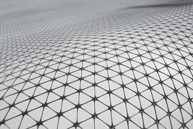
3 A A T1 TTR Tensar TriAx Geogrids have a triangular aperture structure. TDR T1 WDR 60 roll length (longitudinal) roll width (transverse) 1. Getting Started > When placing an order, communicate all pertinent project and/or application criteria, including certification requirements, if any, to your Tensar International Corporation (TIC) representative. It is normally advisable to schedule a pre-construction meeting with this representative and any other appropriate parties at this time. Upon delivery, check the Tensar TriAx Geogrid roll labels to verify that the intended product has been received. For instance, TX5 and TX7 Geogrids have a similar appearance, but different structural characteristics so their distinction is important. Inspect the geogrid to ensure it is free of any flaws or damage that may have occurred during shipping or handling. If variable roll widths are supplied, please confirm that the correct quantities have been delivered. Tensar TriAx Geogrid rolls are assigned distinct nomenclature to distinguish the roll width and length.* Store Tensar TriAx Geogrids in a manner that prevents excessive mud, wet concrete, epoxy or other deleterious materials from coming in contact with and affixing to the geogrid. Store geogrids above 20 F ( 29 C) and Tensar TriAx Geogrid Product Roll Width Roll Length Tensar TriAx TX ft (4 m) 246 ft (75 m) Tensar TriAx TX ft (4 m) 164 ft (50 m) * Additional roll characteristics can be found on page 9 of this guide under Tensar TriAx Roll Characteristics. avoid handling below 14 F ( 10 C). Please contact TIC if project conditions require storing and handling beyond these recommended limits. Tensar TriAx Geogrids may be stored uncovered for up to six (6) months in direct exposure to sunlight without any loss of certifiable structural properties (contact TIC if longer exposure is anticipated). The geogrids may be stored vertically (rolls stood on end) or horizontally in stacks not exceeding four rolls high (Image 1). Anticipate potential issues and resolve them with TIC prior to construction. To contact the local TIC representative for your area, call 800-TENSAR-1. Image 1 Storing the Tensar TriAx Geogrid rolls (horizontally). 3
, it may be beneficial to minimize subgrade disturbance and leave root mats in place.")
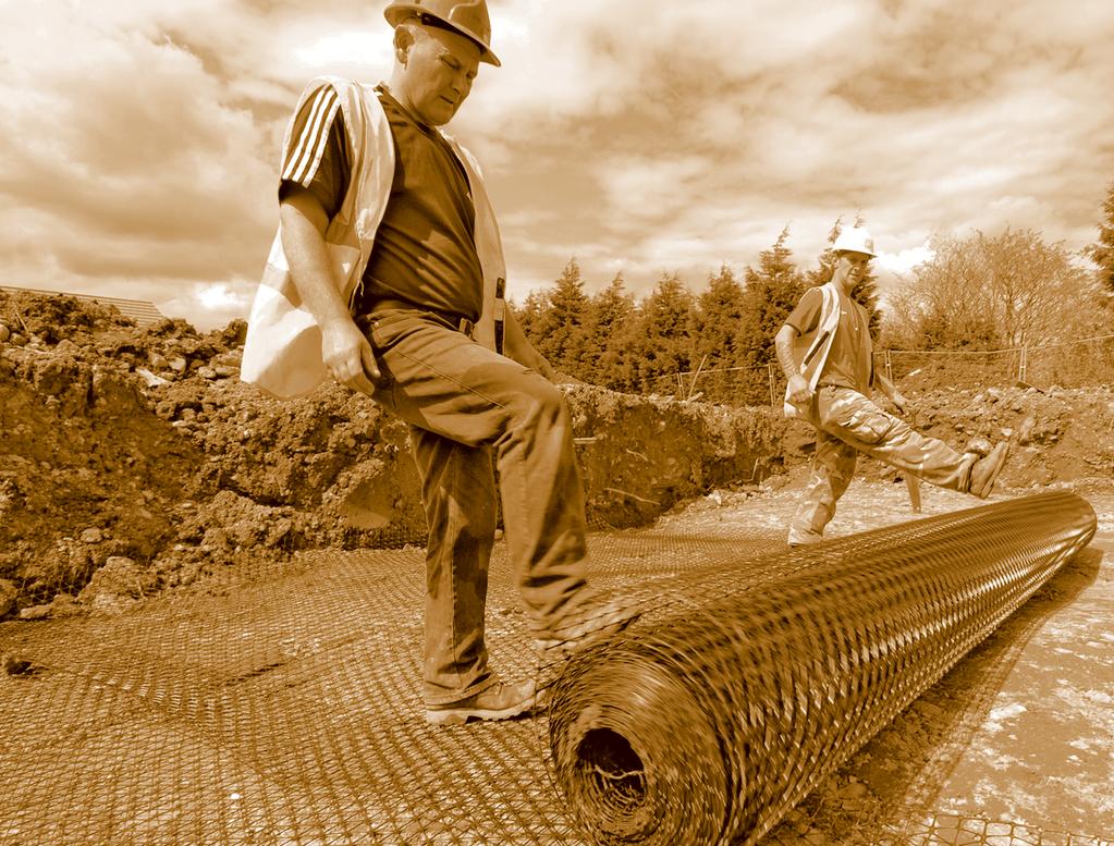
4 Image 2 Rolling out Tensar TriAx Geogrid. 2. Site Preparation > Clear, grub and excavate (if necessary) to the design subgrade elevation, stripping topsoil, deleterious debris and unsuitable material from the site. For very soft soils (CBR < 0.5), it may be beneficial to minimize subgrade disturbance and leave root mats in place. Cut stumps and other projecting vegetation as close and even to the ground surface as practical. For moderately competent soils (CBR > 2), it may be prudent to lightly proof roll the subgrade to locate unsuitable materials. When possible, backdrag to smooth out any ruts. Smooth grade and compact the soils using appropriate compaction equipment. Swampland, peat, muskeg or marshes may be difficult to smooth grade and/or compact. In these situations, create a surface that is as uniformly smooth as possible. Grade or crown the surface for positive drainage away from the construction zone. Place the rolls of Tensar TriAx Geogrid* in position, cut the roll tape and manually unroll the material over the prepared surface (Image 2). In unpaved applications, this surface will always be the subgrade. In paved applications, it may be the subgrade, the granular subbase or an elevation (ex., mid-depth) within the aggregate base course. Fine grained, non-cohesive soils such as silts present unique challenges, especially with the presence of excessive moisture. TIC recommends that a Tensar representative be contacted so that site conditions can be analyzed to ensure the geogrid performance is optimized. * Tensar International Corporation manufactures several different types of geogrid. Selection and optimization depends on structural performance requirements, subgrade and fill parameters, economic considerations and local availability. Note: Routine construction procedures are normally recommended for site preparation. Special measures are rarely required to accommodate Tensar TriAx Geogrids. Subgrade Strength Summary of Tensar TriAx Geogrid Installation Parameters Clear All Vegetation? Geogrid Orientation 3 Geogrid Overlap 4 Nylon Zip Ties? 1, 2 Direct Traffic? 5 Geotextile? 6 CBR M 0.5 N T or L 3 ft Y N Analysis Req d 0.5 M CBR M 2 Usually L 2 3 ft N N Analysis Req d 2 M CBR M 4 Y L 1 2 ft N Limited Analysis Req d 4 M CBR Y L 1 ft N N N Notes: 1. Summary is a generalized presentation; see text for specifics. 2. Y = Yes, normally required; N = No, not normally required. 3. Geogrid Orientation (roll axis in relation to traffic): T = Transverse, L = Longitudinal. 4. General Geogrid Overlap Rule: Overlap = 3 ft for CBR M 1; Overlap = 1 ft for CBR N 4; interpolate between. 5. Direct Traffic pertains only to conventional rubber-tired equipment. 6. Analysis Required = Geotextile required only if filtration criteria is not met by aggregate fill. Table 1


. A notable exception is over very soft subgrades (CBR < 0.")
5 Overlapping Tensar TriAx Geogrid in the field is quick and easy. 3. Placing and Overlapping Geogrid > Unroll the geogrid in the direction of travel so that the long axis of the roll is parallel with channelized traffic patterns. For very soft subgrades (CBR < 0.5), unrolling geogrid transversely or perpendicular to the roadway embankment alignment, may be preferred, particularly if lateral spreading and separation of overlaps is a concern (Table 1). Overlap adjacent rolls along their sides and ends in accordance with Table 1. Overlap ( shingle ) geogrids in the direction that the fill will be spread (Image 3) to avoid peeling of geogrid at overlaps by the advancing fill. To expedite the shingling process, consider placing rolls at the far end of the coverage area first, and work toward the near end from where the fill will be advanced. Weaker subgrades that are easily rutted with conventional construction traffic will require an end-dumping operation. Please refer to page 7 Dumping and Spreading Aggregate Fill for more information. Adjacent geogrid rolls are normally not connected to one another, particularly if fill is placed and spread as described herein (Table 1). A notable exception is over very soft subgrades (CBR < 0.5) where nylon cable ties (or zip ties ) can be effective in helping maintain overlap dimensions. These ties are not considered structural connections, but rather construction aids. In most applications their use is not required. Cut and overlap the geogrid to accommodate curves (Image 4). Cutting may be done with sharp shears (Image 5), a knife-like implement or handheld power (i.e., cutoff ) saws. Cut the geogrid to conform to manhole covers and other immovable protrusions such as vertical utilities. In some cases, especially on cooler days, Tensar TriAx Geogrid will exhibit roll memory where a few feet may roll back upon cutting or reaching the end of the roll. It is recommended that the installer take appropriate measures to ensure that the product lies flat during fill placement. This can be easily achieved by using sod staples, zip ties or simply adding a shovelful of fill to weigh down the product. Safety Note: The use of safety glasses and gloves is highly recommended when installing Tensar TriAx Geogrids. Image 3 Tensar TriAx Geogrid should overlap in the direction of advancing fill. Image 4 Placing Tensar TriAx Geogrid to accommodate curves. Image 5 Cutting Tensar TriAx Geogrid is easily achieved. 5


6 4. Tensioning and Anchoring > Tensar TriAx Geogrids may be anchored in place to aid in maintaining product overlaps and alignment over the coverage area. Before fully unrolling the geogrid, anchor the beginning of the roll, in the center and at the corners, to the underlying surface. Anchor the geogrid with small piles of aggregate fill (Image 6), if necessary. Alternatively, sod staples or washers and pins may also be used by driving them into the subsoil through the apertures of the geogrid. This measure is rarely required unless a significant crown or sloping of the subgrade requires some mechanical anchoring to prevent lateral sliding of the product during fill placement. Additional shoveled piles of aggregate fill may be required to hold the geogrid in place prior to placement of the aggregate fill along overlaps and the ends of rolls. When constructing over very soft soils (CBR < 1.0), it is critically important to maintain overlaps during placement of the fill material. The use of nylon zip ties placed every 5 10 ft is optional to maintain the overlap width recommended in Table 1. Unroll the geogrid. Align and pull it taut to remove wrinkles and laydown slack with hand tension, then secure in place as necessary. Because of the unique manufacturing process and roll sizes of Tensar TriAx Geogrid, maneuvering an unrolled sheet of geogrid is easily achieved. Gloves should be worn while handling Tensar TriAx Geogrids. Image 6 Tensar TriAx Geogrid anchored with small piles of aggregate.

 may drive over the geogrid at very slow speeds (less than 5 mph) and dump aggregate fill as they advance, provided this")
. For very soft subgrades (CBR < 0.")
7 5. Dumping and Spreading Aggregate Fill > Generally, at least 6 in. of compacted aggregate fill is required for the initial lift thickness over a Tensar TriAx Geogrid. However, for very soft conditions, a significantly thicker fill layer will be required to prevent excessive rutting and/or bearing capacity failure of the underlying subgrade soils. Over relatively competent subgrades (CBR > 4, see Table 1), aggregate fill may be dumped directly onto the geogrid. Standard, highway-legal, rubber-tired trucks (end dumps and belly dumps) may drive over the geogrid at very slow speeds (less than 5 mph) and dump aggregate fill as they advance, provided this construction traffic will not cause significant rutting upon bare subgrade. Turns and sudden starts and stops should be avoided. Over softer subgrades, back the trucks up and dump fill from the edge of the previously placed material (Image 7). For very soft subgrades (CBR < 0.5), extreme caution should be taken to avoid overstressing the subgrade soil both during and after fill placement. Please contact a Tensar representative at 800-TENSAR-1 for guidance with constructing over very soft subgrade soils (CBR < 0.5). Do not drive tracked equipment directly on a Tensar TriAx Geogrid. Ensure at least 6 in. of compacted aggregate fill (or the required minimum design fill thickness) is spread between the geogrid and any tracked equipment (Image 8). Over softer subgrades (CBR < 1.5), a lightweight, low ground pressure (LGP) dozer is recommended to evenly push out the initial lift of fill over the exposed geogrid. Care should be taken not to catch the dozer blade or other equipment on the geogrid. The dozer blade should be raised gradually as each lift is pushed out over the geogrid. The desired effect is fill that cascades onto the geogrid, rather than being pushed into it. When building over a soft subgrade, it is desirable to work from stronger to weaker areas. Be aware of geogrid overlaps and advance the aggregate fill with the shingle pattern. Note: When aggregate fill is spread by pushing it over the geogrid with heavy equipment, such as bulldozers, the shoving action may create a wave in the sheet of geogrid ahead of the advancing fill. Shoveled fill can trap this wave and force the geogrid up into the aggregate layer where it can be damaged by the spreading equipment. Pulling the geogrid taut will mitigate laydown slack, thereby removing waving. If significant waving occurs, the shoveled material should be removed to allow the waves to dissipate at the ends and edges of the roll. Image 7 End dumping aggregate fill on top of Tensar TriAx Geogrid over soft subgrade. Image 8 Spreading aggregate fill over Tensar TriAx Geogrid. 7


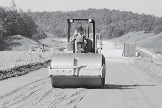
8 Image 10 Compacting the aggregate fill. 6. Compacting > Standard compaction methods may be used unless the soils are very soft. In these cases, static instead of vibratory compaction is prudent, particularly over fine-grained, non-cohesive soils such as silt. Compaction is then achieved using a light roller. Keeping the moisture content of the fill material near optimum will make compaction more efficient. Water spray is most effective with sand fill (see Image 9). For construction over very soft soils, compaction requirements are normally reduced for the initial lift as the primary intent of the initial lift is to achieve a suitable working surface. If rutting or severe pumping occurs under truck or dozer traffic, fill should be added immediately to strengthen the section. Saturated silty subgrades are particularly prone to pumping. In some cases, it may be prudent to cease operations for a period of time, allowing pore pressures to dissipate and the subgrade to stabilize. Otherwise, de-watering measures such as bleeder ditches should be considered to reduce the moisture content of the uppermost silty subgrade layer. Please contact a Tensar representative for more information. Compact aggregate fill to project specifications, after it has been graded smooth and before it is subject to accumulated traffic (Image 10). Inadequate compaction will result in surface rutting under wheel loads. Rutting reduces the total effective thickness of the fill and increases stress on the subgrade.* If the aggregate fill thickness is insufficient to support imposed load(s) when constructing over soft soil, excessive subgrade and surface rutting will result. Measures should be taken to ensure the proper thickness of granular fill is placed atop the geogrid to maximize support and minimize movement at the surface. * Note: Compaction equipment and methods should be appropriate for the type of fill being used, its thickness and the underlying subgrade conditions. Image 9 Moistening the fill before compaction.

9 Tensar TriAx Geogrid Roll Characteristics Roll Width Roll Length Roll Area Roll Weight Product (m) (ft) (m) (ft) (m 2 ) (SY) (kg) (lbs) Tensar TriAx TX Tensar TriAx TX Special Considerations > Make Repairs If Tensar TriAx Geogrids become damaged during or after installation, repair them by patching the area with the following measures: 1. Remove fill from the surface of the damaged geogrid and clear a 3-ft area around the damage. 2. The geogrid patch should cover the damaged area and extend 3 ft beyond it in all directions. Surface Rutting If deep rutting occurs beneath truck wheels, do not grade out the ruts. Rutting is normally indicative of fill that is too thin, too wet or inadequately compacted. Grading out the rut will reduce aggregate fill thickness between the wheel paths and may lead to geogrid exposure. Fill in the ruts with additional specified aggregate fill and compact. This places extra fill where it s needed and may prevent further rutting under channelized traffic. Crown the fill during the grading process to ensure rainfall runoff and to prevent fill saturation. Cold Weather At sub-freezing temperatures, the polymer in a Tensar TriAx Geogrid becomes less resistant to impact and can be fractured by applying a dynamic force (i.e., striking with a hammer). Other aspects of dynamic loading associated with very cold temperatures should be avoided. Tensar Geogrids may be installed in extremely cold climates as long as proper storage and placement procedures are employed. For more information regarding the installation of geogrids in cold climates, please consult a Tensar representative at 800-TENSAR-1. Aggregate Fill Considerations The preferred (not required) fill gradation for roadway applications is well-graded crushed aggregate fill with a maximum particle size of 1½ in. and less than 10% fines (passing #200 sieve). The gradation ranges listed below are recommended for the enhanced load distribution and positive drainage of flexible pavement applications where granular base courses are typically utilized. For unpaved applications, most clean granular fills, including sands, are acceptable. Preferred Fill Gradation Size % Passing 1½ in. 100 ¾ in # # # #200 less than 10 9


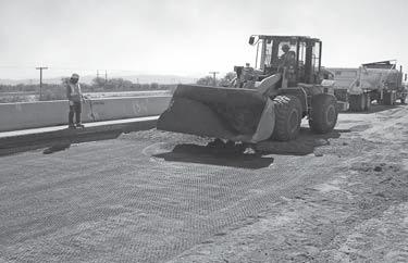
10 Excavating Through Tensar TriAx Geogrid When confined beneath and within compacted fill, the geogrid should pose no significant challenges to post-construction activities like utility trenching or driving/auguring supports for rails, signs or standards. Conventional excavation equipment will shear directly through the geogrid leaving a clean cut as shown in Image 12 Image 12 A backhoe excavation through a Tensar TriAx Geogrid. Tensar TriAx Geogrids will structurally enhance coarser or finer fill gradations, as long as the aggregate fill is compacted and placed at, or just below, optimum moisture content. For coarser fill, a graded filter analysis is recommended to guard against potential contamination from the underlying subgrade (see Table 1 on pg. 4). If the aggregate fill does not meet the requirement(s) of a graded filter over soft and saturated clays and silts it is recommended that a sand filter layer be placed at a minimum depth of 6 in. on top of the geogrid layer. The sand fill thickness may need to be increased in the event the design fill thickness requires a thicker initial lift. The use of uniformly sized coarse granular fill is not recommended as it does not compact well and may rut under repeated wheel loading, despite the improved stability brought about by Tensar TriAx Geogrids. The moisture content of the fill should not exceed optimum. Wet granular fill is not easy to compact and may perform poorly under construction equipment wheel loading. The use of poor quality and/or overly wet fill material that is difficult to prepare and compact over a firm condition, even with Tensar TriAx Geogrid, is not recommended. Preferred Equipment Soft Ground the preferred equipment imposes low contact pressure on the ground surface. This may be done with smaller machinery and/or low ground pressure (LGP) vehicle. Equipment that concentrates heavy loads over a relatively small contact area such as front-end loaders, are not recommended. In all soft ground cases, the fill must be sufficiently thick to avoid overstressing the underlying soils and Tensar TriAx Geogrid. Firm Ground the preferred equipment maximizes productivity for specific construction requirements. Over competent ground, geogrids can be trafficked directly by rubber-tired equipment, making hauling equipment (i.e., dump trucks) and spreading equipment (i.e., motor graders) ideal as shown in Image 11. Spreader boxes are not recommended wrinkling in the geogrid between the screed and wheels of the box and dump trucks can cause slack to become trapped, raising the geogrid up into the aggregate layer. Image 11 Tensar TriAx Geogrid can be trafficked directly by rubber-tired equipment.


11 2009 Tensar International Corporation. SpectraPave4 is a trademark. Restricted Distribution. For technical assistance, call 800-TENSAR-1. SPECTRA_SP4.10_ SpectraPave4-Pro Software for Paved & Unpaved Applications > Tensar International Corporation breaks new ground with the 2010 release of our industry-leading SpectraPave4-Pro Software. This design aid allows the user to accurately predict the performance of geogrid reinforced and unreinforced roads with both paved and unpaved surfaces. The software offers application-specific modules for: Unpaved roads Paved roads Cost Analyses Initial and Life Cycle Unpaved Applications Module Based on the Giroud-Han design methodology, the unpaved applications module incorporates an existing design method, which supports the use of certain geosynthetics, to reduce aggregate thickness requirements and improve the subgrade performance. It indicates the required thickness for unreinforced aggregate fill layers and aggregate fill layers reinforced with Tensar TriAx Geogrids. Paved Applications Module The SpectraPave4-Pro software includes a module for the design of Spectra System Solutions in paved road applications. This module incorporates the design methodology prescribed by AASHTO in their Pavement Design Guide (1993) and also their Interim Standard PP46-01 (2003). Tensar TriAx Geogrids can be used in an AASHTO design to extend the design life of a flexible pavement and/or reduce the thickness of the pavement layers. Cost Analysis Tools The cost analysis tools provide total in-place costs (and savings) for each design option. The results can be represented in dollars per unit area or as a lump sum giving you the flexibility to predict performance and economic benefits for a range of design scenarios. Additionally, the SpectraPave4-Pro software offers the flexibility to evaluate the long-term benefits of Tensar TriAx Geogrids for paved applications using the life cycle cost analysis tool. Technology for Unpaved and Paved Roads with Tensar TriAx Geogrids Technology for Unpaved and Paved Roads with Tensar TriAx Geogrids Version 4.10 For the latest version visit Version 4.10 SpectraPave-Pro software enables engineers to design a Spectra System Solution for paved and unpaved roads. In early 2010, the software will be available free of charge following the completion of a short training module. To apply for training and your free software, visit us online at or call 800-TENSAR-1. 11
12 Tensar International Corporation 5883 Glenridge Drive, Suite 200 Atlanta, Georgia TENSAR-1 Distributed by: 2009, Tensar International Corporation. Certain products and/or applications described or illustrated herein are protected under one or more U.S. patents. Other U.S. patents are pending, and certain foreign patents and patent applications may also exist. Trademark rights also apply as indicated herein. Final determination of the suitability of any information or material for the use contemplated, and its manner of use, is the sole responsibility of the user. Printed in the U.S.A. SPECTRA_IG_9.09
TENSAR TRIAX (TX) Geogrid INSTALLATION GUIDE
 Geogrid INSTALLATION GUIDE") TENSAR TRIAX (TX) Geogrid INSTALLATION GUIDE Tensar TriAx (TX) Geogrids provide soil reinforcement that offers a predictable, cost-effective solution. Tensar Geogrids Tensar TriAx (TX) Geogrids stand the
TENSAR TRIAX (TX) Geogrid INSTALLATION GUIDE Tensar TriAx (TX) Geogrids provide soil reinforcement that offers a predictable, cost-effective solution. Tensar Geogrids Tensar TriAx (TX) Geogrids stand the
TION GUIDE LLA A T INS
 INSTALLATION GUIDE Tensar Geogrids The Spectra System provides soil reinforcement and offers a predictable, cost-effective solution. The Spectra System owes its strength and durability to Biaxial (BX)
GEOSYNTHETICS USED IN SUBGRADE STABILIZATION
 GEOSYNTHETICS USED IN SUBGRADE STABILIZATION Prepared by: TenCate Geosynthetics Americas 365 South Holland Drive Pendergrass, GA 30567 Tel. (706) 693-2226 Fax (706) 693-2044 www.tencate.com July, 2013
Geogrids for Roadway Applications
 Geogrids for Roadway Applications NDLTAP Roundtable Meeting Killdeer ND February 24, 2015 Tensar International Corporation Scott Whaley, P.E. (Georgia) North Dakota Regional Manager Mandan, ND swhaley@tensarcorp.com
Reinforced Soil Slopes (RSS)
") Supplemental Technical Specification for Reinforced Soil Slopes (RSS) SCDOT Designation: SC-M-206-1 (4/16) 1.0 DESCRIPTION 1.1 Construct a reinforced soil slope in accordance with these specifications,
Supplemental Technical Specification for Reinforced Soil Slopes (RSS) SCDOT Designation: SC-M-206-1 (4/16) 1.0 DESCRIPTION 1.1 Construct a reinforced soil slope in accordance with these specifications,
TENSAR TriAx (TX) Geogrid OVERVIEW
 Geogrid OVERVIEW") TENSAR TriAx (TX) Geogrid OVERVIEW 2 Tensar TriAx (TX) Geogrids provide soil stabilization that offers a predictable, cost-effective solution. Tensar Geogrids Tensar TriAx Geogrids stand the test of time,
TENSAR TriAx (TX) Geogrid OVERVIEW 2 Tensar TriAx (TX) Geogrids provide soil stabilization that offers a predictable, cost-effective solution. Tensar Geogrids Tensar TriAx Geogrids stand the test of time,
INS T A LLA T I O N G U I D E
 INS T A LLA T I O N G U I D E TENSAR GEOGRIDS The System is a costeffective and easy-to-install alternative for projects with grade changes. The System owes its long-term performance and durability to
HEAVY-DUTY HAUL ROAD APPLICATION BULLETIN
 HEAVY-DUTY HAUL ROAD APPLICATION BULLETIN FEATURED PROJECT HAUL ROAD Haul Road Applications Like These and Hundreds More HAUL ROAD IN AMAZON RIVER BASIN RAINFOREST, REPUBLIC OF ECUADOR Application: A haul-and-access
SECTION MECHANICALLY STABILIZED EARTH RETAINING WALLS
 SECTION 13100 MECHANICALLY STABILIZED EARTH RETAINING WALLS PART 1 -- GENERAL 1.01 THE REQUIREMENT A. Includes all labor, material, equipment, testing and submittals required to design and complete construction
TION GUIDE ALLA T INS
 INSTALLATION GUIDE TENSAR GEOGRIDS Easier installation makes the Sierra Slope Retention System a more affordable alternative to conventional retaining walls. The Sierra System owes its strength and durability
Geosynthetic Materials for Separation and Stabilization
 Supplemental Technical Specification for Geosynthetic Materials for Separation and Stabilization SCDOT Designation: SC-M-203-1 (4/16) 1.0 DESCRIPTION 1.1 The requirements of this specification consist
Section Specification for Geogrid Base Reinforcement of Flexible Pavement Structures
 Project Name: Project Number: Section 02740 1 GENERAL Specification for Geogrid Base Reinforcement of Flexible Pavement Structures 1.1 SECTION INCLUDES A. Geogrid for use as reinforcement of base or subbase
Retaining Wall Systems
 Retaining Wall Systems Construction & Quality Control Tensar Earth Technologies, Inc. Manual CONSTRUCTION & QUALITY CONTROL This manual provides general guidelines for construction and quality control
Secugrid & Combigrid Geogrids Installation Guide Installation Guidelines: Base Reinforcement Applications
 Secugrid & Combigrid Geogrids Installation Guide Installation Guidelines: Base Reinforcement Applications NAUE GmbH & Co. KG 2005 by NAUE GmbH & Co. KG, Espelkamp-Fiestel, Germany. All rights reserved.
67665_MesaInstallationGuide_2 12/10/07 2:12 PM Page 1 E ID U G TION ALLA T INS
 INSTALLATION GUIDE Introduction The Mesa Retaining Wall Systems from Tensar International Corporation offer superior and costeffective solutions for all of your retaining wall needs. This installation
TOWN OF LAFAYETTE SPECIFICATIONS FOR HIGHWAY CONSTRUCTION. June 1984
 1 TOWN OF LAFAYETTE SPECIFICATIONS FOR HIGHWAY CONSTRUCTION June 1984 1. DEFINITIONS APPROVAL, APPROVED, ACCEPTED OR WORDS OR TERMS OF SIMILAR MEANING: Written approval of the Highway Superintendent. BASE
CITY OF LETHBRIDGE SECTION INFRASTRUCTURE SERVICES Page 1 of 7 GRANULAR BASE PREP
 INFRASTRUCTURE SERVICES Page 1 of 7 1.0 GRANULAR BASE AND SUB-BASE 1.1 DESCRIPTION.1 This section specifies requirements for supplying, producing, hauling placing and compacting processed gravel or quarried
CONCRETE SEGMENTAL RETAINING WALL SYSTEM
 CONCRETE SEGMENTAL RETAINING WALL SYSTEM PART 1: GENERAL SPECIFICATIONS 1.01 Work Included A. Work shall consist of furnishing and constructing a Rockwood Classic 8, Classic 6 and Legend unit segmental
SECTION PERMEABLE INTERLOCKING CONCRETE UNIT PAVEMENT
 SECTION 32 14 13 19 PERMEABLE INTERLOCKING CONCRETE UNIT PAVEMENT SECTION 32 14 13 19 PERMEABLE INTERLOCKING CONCRETE UNIT PAVEMENT PART 1 - GENERAL 1.1 SUMMARY A. Section Includes: 1. Permeable Articulating
SECTION SOILS REPORT
 SECTION 02300 SOILS REPORT 1. GENERAL: 1.1 All work included under this heading shall be subject to the General Conditions of the entire operation. This Contractor is required to refer especially thereto.
Suggested Guidelines for Hot Mix Asphalt (HMA) Underlayment in Track by AREMA Committee l-sub Committee No. 2 - Ballast.
 Underlayment in Track by AREMA Committee l-sub Committee No. 2 - Ballast.") Suggested Guidelines for Hot Mix Asphalt (HMA) Underlayment in Track by AREMA Committee l-sub Committee No. 2 - Ballast OVERVIEW June 11, 1998 The purpose of these Suggested Guidelines is to provide 1)
Suggested Guidelines for Hot Mix Asphalt (HMA) Underlayment in Track by AREMA Committee l-sub Committee No. 2 - Ballast OVERVIEW June 11, 1998 The purpose of these Suggested Guidelines is to provide 1)
Installation Guidelines
 815 NE 172 nd Avenue Vancouver, WA 98684 877-694-0141 Installation Guidelines Installation steps include job planning, layout, excavating and preparing the soil subgrade, applying geotextiles (optional),
BIAXIAL GEOGRID REINFORCEMENT
 F O R N I T BIAXIAL GEOGRID REINFORCEMENT FORNIT GEOGRIDS. DISCOVER THE DIFFERENCE. When you re constructing paved roads, nothing offers support like Fornit biaxial geogrids. Strong and durable, they reinforce,
SECTION EXCAVATION AND EMBANKMENT. B. Subbase Grading A samples for gradation analysis.
 PART 1 GENERAL 1.1 DESCRIPTION A. The WORK under this Section includes providing all labor, materials, tools and equipment necessary for excavation and embankment construction to the lines, grades and
SPECIFICATIONS FOR PRECAST MODULAR BLOCK RETAINING WALL SYSTEM (revised 5/8/7)
") Page 1 of 7 STONE STRONG SYSTEMS SPECIFICATIONS FOR PRECAST MODULAR BLOCK RETAINING WALL SYSTEM (revised 5/8/7) PART 1: GENERAL 1.01 Description A. Work includes furnishing and installing precast modular
Page 1 of 7 STONE STRONG SYSTEMS SPECIFICATIONS FOR PRECAST MODULAR BLOCK RETAINING WALL SYSTEM (revised 5/8/7) PART 1: GENERAL 1.01 Description A. Work includes furnishing and installing precast modular
SPECIFICATIONS FOR PRECAST MODULAR BLOCK RETAINING WALL SYSTEM (revised 9/17/18)
") Page 1 of 8 STONE STRONG SYSTEMS SPECIFICATIONS FOR PRECAST MODULAR BLOCK RETAINING WALL SYSTEM (revised ) PART 1: GENERAL 1.01 Description A. Work includes furnishing and installing precast modular blocks
Page 1 of 8 STONE STRONG SYSTEMS SPECIFICATIONS FOR PRECAST MODULAR BLOCK RETAINING WALL SYSTEM (revised ) PART 1: GENERAL 1.01 Description A. Work includes furnishing and installing precast modular blocks
SECTION MECHANICALLY STABILIZED EARTHEN SLOPES. Display hidden notes to specifier by using Tools / Options / View / Hidden Text.
 PART 1 GENERAL SECTION 02260 MECHANICALLY STABILIZED EARTHEN SLOPES Display hidden notes to specifier by using Tools / Options / View / Hidden Text. 1.1 SECTION INCLUDES A. ** NOTE TO SPECIFIER ** Delete
SECTION PERMEABLE INTERLOCKING CONCRETE UNIT PAVEMENT
 SECTION 32 14 13 19 PERMEABLE INTERLOCKING CONCRETE UNIT PAVEMENT SECTION 32 14 13 19 PERMEABLE INTERLOCKING CONCRETE UNIT PAVEMENT PART 1 - GENERAL 1.1 SUMMARY A. Section Includes: 1. Permeable Articulating
TENCATE MIRAFI RSi MULTIFUNCTIONAL WOVEN GEOTEXTILES
 TENCATE MIRAFI RSi MULTIFUNCTIONAL WOVEN GEOTEXTILES IDEAL FOR TEMPORARY ACCESS ROADS Mirafi RSI is designed to maximise use of site -won materials in temporary roads, haul roads and site access road construction.
GEOSYTHETIC SLOPE SPEC-V0704rev.doc STANDARD SPECIAL PROVISION FOR GEOSYNTHETIC REINFORCED SLOPE CONSTRUCTION
 GEOSYTHETIC SLOPE SPEC-V0704rev.doc STANDARD SPECIAL PROVISION FOR GEOSYNTHETIC REINFORCED SLOPE CONSTRUCTION I. DESCRIPTION - This work consists of furnishing the required materials and construction of
SECTION TRENCHING, BACKFILLING, COMPACTION AND GENERAL GRADING
 PART 1 GENERAL SECTION 02221 TRENCHING, BACKFILLING, COMPACTION AND GENERAL GRADING 1.01 SECTION INCLUDES A. Excavation, dewatering and backfilling with compaction of trenches for pipes, conduits, channels
INDEX DESCRIPTION MATERIALS APPROVAL FOR BASE COURSE CONSTRUCTION MEASUREMENT PAYMENT 6
 03005_Jan31_2018.pdf Page 1 of 6 INDEX Page 03005-1 DESCRIPTION 2 03005-2 MATERIALS 2 03005-3 APPROVAL FOR BASE COURSE 3 03005-4 CONSTRUCTION 3 03005-5 MEASUREMENT 6 03005-6 PAYMENT 6 03005_Jan31_2018.pdf
StormTech Construction Guide
 A division of StormTech solid end caps and pre-cored end caps StormTech chambers StormTech manifolds and fittings Acceptable fill materials per Table 1 Woven and non-woven geotextiles 80-7 DC REQUIRED
StormTech Construction Guide
 Stormtech MC-3500 Construction Guide 12/31/14 11:18 AM Page 1 M /M 00 35 C- A division of REQUIRED MATERIALS AND EQUIPMENT LIST 00 45 C- StormTech Construction Guide Detention Retention Water Quality Acceptable
MINING UNDERGROUND AND SURFACE SYSTEMS. system overview
 MINING UNDERGROUND AND SURFACE SYSTEMS system overview Tensar Mining Systems are designed to enhance value, maximize return and reduce overall costs for your mining projects. Tensar Mining Systems Our
StormTech Construction Guide
 M /M 00 35 C- A division of REQUIRED MATERIALS AND EQUIPMENT LIST 00 45 C- StormTech Construction Guide Detention Retention Water Quality Acceptable fill materials per Table 1 Woven and non-woven geotextiles
SECTION ASPHALT PAVING
 SECTION 02500 ASPHALT PAVING PART 1 GENERAL 1.1 RELATED DOCUMENTS a) Drawings and general provisions of the Contract, including the General and Supplementary General Conditions and Division 00 & 01 specification
CONSTRUCTION SPECIFICATION FOR UNTREATED SUBBASE, BASE, SURFACE, SHOULDER, SELECTED SUBGRADE, AND STOCKPILING
 ONTARIO PROVINCIAL STANDARD SPECIFICATION METRIC OPSS.PROV 314 NOVEMBER 2015 CONSTRUCTION SPECIFICATION FOR UNTREATED SUBBASE, BASE, SURFACE, SHOULDER, SELECTED SUBGRADE, AND STOCKPILING TABLE OF CONTENTS
1.02 RELATED WORK: Refer to the following sections for related work: Section 4000-Concrete Materials and Methods
 SECTION 2000- EARTHWORK PART 1- GENERAL 1.01 SCOPE: This Section covers excavation, fill, and compaction of earth and rock for roadway, embankments, structural foundations, and planted areas. Topics include
MSCAA /04 ITEM P-219 RECYCLED CONCRETE CRUSHED AGGREGATE BASE COURSE DESCRIPTION MATERIALS
 219-1.1 ITEM P-219 RECYCLED CONCRETE CRUSHED AGGREGATE BASE COURSE DESCRIPTION This item consists of a base course composed of crushed recycled concrete aggregate, crushed to meet a particular gradation,
Section 25 Aggregate Subbase
 Black text from standard FAA spec Strikeout text deletions from FAA standard spec Blue text additions to FAA standard spec Red text notes to the Engineer/won t appear in spec I. DESCRIPTION A. GRANULAR
ICBO Evaluation Service, Inc Workman Mill Road, Whittier, California
 ER-5435 Reissued May 1, 2002 ICBO Evaluation Service, Inc. 5360 Workman Mill Road, Whittier, California 90601 www.icboes.org Filing Category: DESIGN Masonry MESA RETAINING BLOCK WALL SYSTEM TENSAR EARTH
Wmega Retaining Wall Specification
 Wmega Retaining Wall Specification 1. General 1.01 Description A. This work shall consist of furnishing and installing an Ωmega Segmental Retaining Wall System in accordance with these specifications and
SECTION EMBANKMENT
 02260-1 of 8 SECTION 02260 EMBANKMENT 02260.01 GENERAL A. Description 1. Embankment shall be formed of suitable material obtained from General, Structure, Borrow, Trench, and other excavations included
BENTOMAT CL GEOSYNTHETIC CLAY LINER SPECIFICATION GUIDELINES
 BENTOMAT CL GEOSYNTHETIC CLAY LINER SPECIFICATION GUIDELINES This specification is intended for use as a GENERAL GUIDELINE for developing a specification for a specific project. It is NOT intended as a
WIND FARM APPLICATION BULLETIN
 WIND FARM APPLICATION BULLETIN FEATURED PROJECT Renaico Wind Farm Working with the Wind Energy Industry & Developing Integrated Construction Solutions APPLICATION: In the Araucanía Region of Chile, forty-four
STANDARD SPECIFICATIONS FOR PUBLIC WORKS CONSTRUCTION CITY OF WEST BEND, WISCONSIN SECTION 300 EARTHWORK, GRADING, AND GRAVELING
 STANDARD SPECIFICATIONS FOR PUBLIC WORKS CONSTRUCTION CITY OF WEST BEND, WISCONSIN SECTION 300 EARTHWORK, GRADING, AND GRAVELING Section Number Title 301 GENERAL 302 MATERIALS SPECIFICATIONS 303 CLEARING
B. Base Course: Aggregate layer placed between the subbase course and hot-mix asphalt paving.
 SECTION 312000 - EARTH MOVING PART 1 - GENERAL 1.1 SUMMARY A. Section Includes: 1. Excavating and filling for rough grading the Site. 2. Preparing subgrades for walks, curbs, pavements, and turf and grasses.
2. Pavement Materials: Consist of flexible or rigid pavements, typically HMA or PCC, respectively, or a composite of the two.
 Design Manual Chapter 6 - Geotechnical 6C - Pavement Systems 6C-1 Pavement Systems A. General Information This section addresses the importance of pavement foundations and the potential for pavement problems
City of Regina Standard Construction Specification SECTION 2350 PLACEMENT OF ASPHALTIC CONCRETE SURFACE 1.0 GENERAL. 1.1 Scope
 1.0 GENERAL 1.1 Scope 2.0 PRODUCTS 1.1.1 The work shall consist of placing asphaltic concrete to a compacted thickness conforming to the lines, grades, and cross-sections as shown on the plan or as designated
NORTH HARRIS COUNTY REGIONAL WATER AUTHORITY PORTLAND CEMENT. Section PORTLAND CEMENT STABILIZED SUBGRADE
 PART 1 GENERAL 1.01 SUMMARY Section 02338 PORTLAND CEMENT This Section includes foundation course of Portland cement stabilized natural subgrade material. 1.02 MEASUREMENT AND PAYMENT A. Unit Prices. 1.
StormTech Construction Guide An company
 SC-160LP StormTech Construction Guide An company REQUIRED MATERIALS AND EQUIPMENT LIST IMPORTANT NOTES: A. This installation guide provides minimum requirements for proper installation of chambers. Non-adherence
PERMEABLE INTERLOCKING PAVERS
 PERMEABLE INTERLOCKING PAVERS PART 1 - GENERAL 1.01 SECTION INCLUDES A. Subgrade Preparation B. Placement of Storage Aggregate C. Placement of Filter Aggregate D. Placement of Bedding Course E. Placement
ROADWAY PAVEMENT OPTIMIZATION. system overview
 ROADWAY PAVEMENT OPTIMIZATION system overview Table of Contents Paved Roads and the Need for Innovation...2 The Spectra System Reduces Construction Costs and Long-term Maintenance Needs... 3 How Tensar
SECTION EROSION CONTROL DEVICES
 SECTION 02374 PART 1 GENERAL EROSION CONTROL DEVICES 1.1 SUMMARY A. Section Includes: 1. Diversion Channels. 2. Rock Energy Dissipator. 3. Paved Energy Dissipator. 4. Rock Basin. 5. Rock Barriers. 6. Sediment
SECTION CONCRETE SEGMENTAL RETAINING WALL SYSTEM
 SECTION 02832 CONCRETE SEGMENTAL RETAINING WALL SYSTEM PART 1.: GENERAL 1.01 WORK INCLUDED A. This section includes the following: The Specifications on furnishing the design, materials and labor required
SECTION RIPRAP, BOULDERS, AND BEDDING
 SECTION 31 37 00 RIPRAP, BOULDERS, AND BEDDING PART 1 GENERAL 1.01 SECTION INCLUDES A. The WORK includes excavation, grading, and installation of riprap, boulders, soil riprap, void-filled riprap, and
ASPHALT MIX DESIGNER
 ASPHALT MIX DESIGNER EFFECT OF MIX DESIGN ON PERFORMANCE AND CONSTRUCTION OF HMA Module 8 Module 8 1, July 2005 8-1 QUALITY Meets or Exceeds the Expectations or Needs of the Customer Module 8 2, July 2005
GROUNDtrax GROUNDGRIDZ
 INSTALLATION GUIDE The product is asymmetric and must be lifted by placing the hands on the diagonally opposed corners of the central paver (as shown). 1. Place grids onto the prepared well consolidated
SECTION 503 TEMPORARY PAVEMENT RESTORATION
 SECTION 503 TEMPORARY PAVEMENT RESTORATION 503-1 DESCRIPTION: This work consists of furnishing, placing, compacting, and maintaining a temporary pavement surface suitable for driving in accordance with
Item P-219 Recycled Concrete Aggregate Base Course
 Item P-219 Recycled Concrete Aggregate DESCRIPTION 219-1.1 This item consists of a base course composed of recycled concrete aggregate, crushed to meet a particular gradation, constructed on a prepared
STATE OF OHIO DEPARTMENT OF TRANSPORTATION SUPPLEMENTAL SPECIFICATION 863 REINFORCED SOIL SLOPES. October 19, 2012
 STATE OF OHIO DEPARTMENT OF TRANSPORTATION 863.01 Description 863.02 Materials 863.03 Construction 863.04 Method of Measurement 863.05 Basis of Payment SUPPLEMENTAL SPECIFICATION 863 REINFORCED SOIL SLOPES
SECTION SPECIFICATION FOR MECHANICALLY STABILIZED EARTH TWO STAGE WALL SYSTEM
 SECTION 02830 SPECIFICATION FOR MECHANICALLY STABILIZED EARTH TWO STAGE WALL SYSTEM ## THIS SECTION IS WRITTEN IN CSI 3-PART FORMAT AND IN CSI PAGE FORMAT. NOTES TO THE SPECIFIER, SUCH AS THIS, ARE INDICATED
SECTION PERMEABLE INTERLOCKING CONCRETE PAVEMENT (1995 MasterFormat Section 02795)
") SECTION 32 14 13.19 PERMEABLE INTERLOCKING CONCRETE PAVEMENT (1995 MasterFormat Section 02795) Note: This guide specification for U.S. applications describes construction of permeable interlocking concrete
SECTION 32 14 13.19 PERMEABLE INTERLOCKING CONCRETE PAVEMENT (1995 MasterFormat Section 02795) Note: This guide specification for U.S. applications describes construction of permeable interlocking concrete
SECTION MECHANICALLY STABILIZED EARTH 1.01 SUMMARY
 SECTION 028300 PART 1 GENERAL 1.01 SUMMARY A. Section includes Basis of Design Mechanically Stabilized Earth System: SierraScape Mechanically Stabilized Earth (MSE) retaining wall system having high density
StormTech Construction Guide
 REQUIRED MATERIALS AND EQUIPMENT LIST An 80-7 DC 0/ 74 C/S 10-3 SC StormTech Construction Guide company ~ Bc^a\CTRW b^[xs T]S RP_b P]S _at R^aTS T]S RP_b ~ Bc^a\CTRW RWP\QTab ~ Bc^a\CTRW \P]XU^[Sb P]S
Foundation improvement system. system overview
 Foundation improvement system system overview By distributing loads over a larger area, the Dimension System creates a solid foundation for engineered structures. Tensar Geogrids The Dimension System owes
SECTION EARTHWORK
 SECTION 02200 EARTHWORK PART 1 - GENERAL 1.01 WORK INVOLVED A. Provide all labor, materials and equipment as required for all excavation, grading, providing borrow materials, hauling, placing and compacting
GEOSYNTHETICS ENGINEERING: IN THEORY AND PRACTICE
 GEOSYNTHETICS ENGINEERING: IN THEORY AND PRACTICE Prof. J. N. Mandal Department of civil engineering, IIT Bombay, Powai, Mumbai 400076, India. Tel.022-25767328 email: cejnm@civil.iitb.ac.in Module-5 LECTURE-
BASE CONSTRUCTION MATERIALS A Aggregate
 BASE CONSTRUCTION 2211 AGGREGATE BASE 2211.1 DESCRIPTION This work consists of placing aggregate base. 2211.2 MATERIALS A Aggregate... 3138 Provide the class of aggregate as required by the contract. 2211.3
SECTION 28 AGGREGATE BASE COURSE (FAA P-208) [For base course under runway and taxiway surfaces, use Section 29, FAA Item P-209.]
![SECTION 28 AGGREGATE BASE COURSE (FAA P-208) [For base course under runway and taxiway surfaces, use Section 29, FAA Item P-209.]](/thumbs/86/93513071.jpg "SECTION 28 AGGREGATE BASE COURSE (FAA P-208) [For base course under runway and taxiway surfaces, use Section 29, FAA Item P-209.]") 28-1 GENERAL SECTION 28 AGGREGATE BASE COURSE (FAA P-208) The Contractor shall perform all work required by the plans and specifications for construction of aggregate base course for, use under runway
28-1 GENERAL SECTION 28 AGGREGATE BASE COURSE (FAA P-208) The Contractor shall perform all work required by the plans and specifications for construction of aggregate base course for, use under runway
SPECIAL SPECIFICATION 3153 Geosynthetic Clay Liner
 2004 Specifications CSJ 0215-02-029, etc. SPECIAL SPECIFICATION 3153 Geosynthetic Clay Liner 1. Description. Install a Geosynthetic Clay Liner (GCL) in accordance with this specification and as shown on
DIVISION 4100 SITEWORK
 DIVISION 4100 SITEWORK SECTION 4115 EARTHWORK PART 1 - GENERAL 1.01 SCOPE This section covers the grading and compaction of excavations, embankments, structural foundations, and planted areas. 1.02 REFERENCES
PaveDrain Installation Manual. Table of Contents. Hand-Placement of individual PaveDrain Units. PaveDrain End Cap
 Installation Manual PaveDrain Installation Manual Table of Contents Section 1: Base Preparation Section 2: Hand-Placement of individual PaveDrain Units Section 3: Mattress Installation Section 4: PaveDrain
FOUNDATION improvement system. system overview
 FOUNDATION improvement system system overview By distributing loads over a larger area, the Dimension system creates a solid foundation for engineered structures. TENSAR GEOGRIDS The Dimension System owes
ITEM 252 IN-PLACE FULL DEPTH COLD FLEXIBLE PAVEMENT RECYCLING
 AFTER NOVEMBER 1, 2008 ITEM 252 IN-PLACE FULL DEPTH COLD FLEXIBLE PAVEMENT RECYCLING 252.1 Description. This work shall consist of a stabilized base course composed of a mixture of the existing bituminous
SECTION ASPHALT CONCRETE
 SECTION 02740 ASPHALT CONCRETE PART 1. GENERAL 1.01 SECTION INCLUDES A. Work includes but is not limited to the following: 1.02 RELATED SECTIONS 1. Provide all material, labor, and equipment to prepare
Tensar. TriAx Geogrid & New Advancements in Onsite Validation of Designs (APLT) Andrew W. Isenhour, PE Mid-Atlantic Regional Manager NC/SC/VA
 Andrew W. Isenhour, PE Mid-Atlantic Regional Manager NC/SC/VA") Tensar TriAx Geogrid & New Advancements in Onsite Validation of Designs (APLT) Andrew W. Isenhour, PE Mid-Atlantic Regional Manager NC/SC/VA Who We Are Tensar Group Overview Tensar Corporation is the parent
Tensar TriAx Geogrid & New Advancements in Onsite Validation of Designs (APLT) Andrew W. Isenhour, PE Mid-Atlantic Regional Manager NC/SC/VA Who We Are Tensar Group Overview Tensar Corporation is the parent
SECTION TRENCHING
 SECTION 31 23 17 TRENCHING PART 1 GENERAL 1.1 SUMMARY A. Section Includes: 1. Excavating trenches for utilities and utility structures. 2. Bedding. 3. Backfilling and compacting to subgrade elevations.
Best Practices for Building High-Performance Resource Roads. Road Drainage. Developed by: The Roads and Infrastructure Group
 Best Practices for Building High-Performance Resource Roads Road Drainage Developed by: The Roads and Infrastructure Group THIS GUIDE IS INTENDED FOR EQUIPMENT OPERATORS CONSTRUCTION CONTRACTORS FIELD
CITY OF LETHBRIDGE SECTION Construction Specifications SIDEWALK CONSTRUCTION PAGE 1 of 5
 Construction Specifications SIDEWALK CONSTRUCTION PAGE 1 of 5 1.0 EXCAVATION AND FILL 1.1 GENERAL.1 The excavation or fill shall be made to provide proper grade, lines and crosssection for the laying of
Geosynthetic Solutions
 Geosynthetic Solutions For Paved and Unpaved Applications Dave Lipomi Tensar Products and Applications Geogrids Uniaxial-Walls and Reinforced Slopes Biaxial-Reinforced Slopes, Roads, Foundations, Crane
SECTION ASPHALT PAVING AND SURFACING
 SECTION 02500 ASPHALT PAVING AND SURFACING PART 1 - GENERAL 1.01 WORK INCLUDED A. Traffic control as required to divert vehicular and pedestrian traffic around construction. B. Spreading and compacting
Construction Specification for General Excavation
 Engineering & Construction Services Division Standard Specifications for Road Works TS 2.10 September 2018 for General Excavation Table of Contents TS 2.10.01 SCOPE... 2 TS 2.10.02 REFERENCES... 2 TS 2.10.03
CITY OF FARGO SPECIFICATIONS GEOTEXTILES AND GEOGRIDS
 GEOTEXTILES AND GEOGRIDS PART 1 DESCRIPTION OF WORK The work to be done under this section of the Specifications and the accompanying plans consists of all labor, material, accessories, and equipment necessary
ROADWAY DRAINAGE SYSTEM SYSTEM OVERVIEW
 ROADWAY DRAINAGE SYSTEM SYSTEM OVERVIEW RoaDrain Roadway Drainage System: Enhance Pavement Performance with Synthetic Aggregate Water retention within a pavement layer is a primary cause of pavement failure.
ROADWAY DRAINAGE SYSTEM SYSTEM OVERVIEW
 ROADWAY DRAINAGE SYSTEM SYSTEM OVERVIEW RoaDrain Roadway Drainage System: Enhance Pavement Performance with Synthetic Aggregate Water retention within a pavement layer is a primary cause of pavement failure.
Utility Cut Restoration
 Design Manual Chapter 9 - Utilities 9D - Utility Cut Restoration 9D-1 Utility Cut Restoration A. General Utility cuts are made in existing pavement sections to install a myriad of utilities and to repair
Secudrain WD The NAUE Geosynthetic Drainage System Installation Recommendations
 Secudrain WD The NAUE Geosynthetic Drainage System Installation Recommendations NAUE GmbH & Co. KG Product description.......2 Shipment.....2 Storage and handling......2 Verification......3 Secudrain installation......3
CITY OF FARGO SPECIFICATIONS AGGREGATE BASES
 AGGREGATE BASES PART 1 DESCRIPTION OF WORK The work to be done under this section of the Specifications and the accompanying plans consists of all labor, material, accessories, and equipment necessary
SECTION SEGMENTAL CONCRETE UNIT MASONRY RETAINING WALL MAXIMUM HEIGHT OF 5-0 HIGH
 DIVISION 32 EXTERIOR IMPROVEMENTS SECTION 32 32 23.13 SEGMENTAL CONCRETE UNIT MASONRY RETAINING WALL MAXIMUM HEIGHT OF 5-0 HIGH PART 1: GENERAL 1.01 Scope of Standards A. This standard provides general
SPECIFICATION FOR CORNERSTONE GEOGRID REINFORCED SEGMENTAL RETAINING WALL SYSTEM
 CornerStone Specifications Geogrid Reinforced SPECIFICATION FOR CORNERSTONE GEOGRID REINFORCED SEGMENTAL RETAINING WALL SYSTEM PART 1: GENERAL 1.01 Description The work consists of supplying and installing
GUIDELINE FOR PLANTED INFILL INSTALLATIONS. Please read prior to installation, and have proper equipment and safety precautions in place.
 GUIDELINE FOR PLANTED INFILL INSTALLATIONS Please read prior to installation, and have proper equipment and safety precautions in place. For additional information please visit our website at www.soilretention.com
SECTION TRENCHING, BACKFILLING AND COMPACTION. B. Provide necessary sheeting, shoring and bracing.
 SECTION 02221 TRENCHING, BACKFILLING AND COMPACTION PART 1 GENERAL 1.01 WORK INCLUDED A. Excavation for piped utility material. B. Provide necessary sheeting, shoring and bracing. C. Prepare trench bottom
4 STANDARD SPECIFICATIONS FOR ROAD AND BRIDGE CONSTRUCTION (SSRBC) 2015 STANDARD SPECIFICATIONS
 2015 STANDARD SPECIFICATIONS") Student Manual Lesson 4 Specifications Lesson 4 STANDARD SPECIFICATIONS FOR ROAD AND BRIDGE CONSTRUCTION (SSRBC) 2015 STANDARD SPECIFICATIONS 4-1 Version 1.0 1/15 4 1 Student Manual Lesson 4 Specifications
Student Manual Lesson 4 Specifications Lesson 4 STANDARD SPECIFICATIONS FOR ROAD AND BRIDGE CONSTRUCTION (SSRBC) 2015 STANDARD SPECIFICATIONS 4-1 Version 1.0 1/15 4 1 Student Manual Lesson 4 Specifications
2.1 Backfill - General
 2.1 Backfill - General Excavations are made for the purpose of constructing bridge substructure elements, and consequently requiring competent backfill material. The backfill material must be adequately
Based on conversations with WSP personnel, the following items require Paterson s review:
 consulting engineers memorandum to: 2015-2017 RR Ltd - Mr. Jonah Bonn - jbonn@firstbay.ca to: WSP - Mr. James Johnston - james.johnston@wsp.com re: Parking Lot Rehabilitation Pavement Structure Recommendations
Geotechnical Investigation Long Timber Brewing Building Highway 99 and Kelly Street Monroe, Oregon TABLE OF CONTENTS
 Highway 99 and Kelly Street TABLE OF CONTENTS PROJECT INFORMATION... 1 FIELD EXPLORATION... 1 SITE CONDITIONS... 2 Surface Conditions:... 2 Subsurface Conditions:... 2 FILL.... 2 Topsoil.... 2 Clay Alluvium....
SECTION PERMEABLE INTERLOCKING CONCRETE UNIT PAVEMENT SECTION PERMEABLE INTERLOCKING CONCRETE UNIT PAVEMENT
 SECTION 32 14 13.19 PERMEABLE INTERLOCKING CONCRETE UNIT PAVEMENT SECTION 32 14 13 19 PERMEABLE INTERLOCKING CONCRETE UNIT PAVEMENT PART 1 - GENERAL 1.1 SUMMARY A. Section Includes: 1. Permeable Articulating
A. Texas Department Transportation 2004 Standard Specifications for Construction of Highways, Streets and Bridges (TxDOT):
:") SECTION 31 32 13.16 CEMENT STABILIZATION PART 1 GENERAL 1.1 SCOPE OF WORK A. This Section pertains to the specifications for cement stabilization of sandy or silty soil and consists of pulverizing, addition
SECTION 31 32 13.16 CEMENT STABILIZATION PART 1 GENERAL 1.1 SCOPE OF WORK A. This Section pertains to the specifications for cement stabilization of sandy or silty soil and consists of pulverizing, addition