UL PCB Recognition what is it & why do you need to know about it
|
|
|
- Mitchell Rodney Jennings
- 6 years ago
- Views:
Transcription


1 UL PCB Recognition what is it & why do you need to know about it Presented by Emma Hudson NCAB Customer Event March 2015 UL and the UL logo are trademarks of UL LLC 2015
2 Agenda What is UL and what are its aims Drivers for UL PCB Recognition Purpose of UL PCB Requirements Benefits of buying UL Recognized PCBs Types of UL PCB Recognition Elements controlled for a Recognized PCB Where to view UL PCB Recognition Considerations when specifying a PCB that needs to be UL Recognized UL Marking Requirements on the PCB 2


3 Your presenter Emma Hudson Lead PCB Engineer for Europe & Latin America at UL With UL for 9 years Formerly Process & Materials Laboratory Manager for an Automotive Electronics manufacturer BEng (Hons) in Materials Technology, gained at Coventry University in Tel: Emma.Hudson@UL.com 3
4 Agenda What is UL and what are its aims Drivers for UL PCB Recognition Purpose of UL PCB Requirements Benefits of buying UL Recognized PCBs Types of UL PCB Recognition Elements controlled for a Recognized PCB Where to view UL PCB Recognition Considerations when specifying a PCB that needs to be UL Recognized UL Marking Requirements on the PCB 4
5 What is UL? Underwriters Laboratories (UL) A global independent safety science company with more than 10,000 employees and more than 150 laboratories Over a century of expertise in innovating safety solutions A global leader in standards development, testing and certification 5
6 The aims of UL? Working for a Safer World Since 1894 Promote safe living and working environments for people by the application of safety science and hazard-based safety engineering Support the production and use of products which are physically and environmentally safe and to apply our efforts to prevent or reduce loss of life and property Advance safety science through research and investigation 6
7 What do UL do? WE Certify Validate Test Inspect Audit Advise & Educate 7
8 Agenda What is UL and what are its aims Drivers for UL PCB Recognition Purpose of UL PCB Requirements Benefits of buying UL Recognized PCBs Types of UL PCB Recognition Elements controlled for a Recognized PCB Where to view UL PCB Recognition Considerations when specifying a PCB that needs to be UL Recognized UL Marking Requirements on the PCB 8


9 Recognition Leads to Product Safety Listing UL Recognition of components is driven by end product safety concerns around: Fire: added fuel; ignitability Electric Shock: reduced spacings; insulation breakdown, mechanical strength 9

 V-1, MOT for")
 V-1, 105C MOT* UL 508 (Industrial")

10 Recognition Leads to Product Safety Listing Many end-product Standards require UL Recognized PCBs to be used Each standard will have different requirements for the PCB based on the application within the end-product For example: IEC (Audio & Video Equipment) V-0 orv-1 based on power requirements* IEC (Information Technology Equipment) V-1, MOT for application, and Direct Support compliant* IEC (Medical Equipment) V-2 min, MOT for application* IEC (Equipment for Laboratory Use) V-1, 105C MOT* UL 508 (Industrial Control Equipment) V-2 min, MOT for application, and Direct Support compliant may also be needed* * Requirements are always APPLICATION DEPENDENT and should be verified before defining what PCB type is required 10
11 Demand Driver for UL PCB Certification End Product Hazard Failure Mechanism Board Feature Test Test Method PCB Parameter Metal type Bond strength UL 796 MOT conductor adhesion Blistering/Delam i l UL 796 MOT Paste type conductor adhesion Conductive Paste Adhesion UL 796 MOT Electric Shock Reduce Spacings Silver conductors Plating adhesion Warping / Cracking Silver Migration UL 796 MOT Plating adhesion UL 796 MOT Delamination UL 796 MOT Environmental UL 746E/ CTI Contamination UL746A DSR Insulation Breakdown Board thickness Dielectric UL 746E/ RTI / MOT / Strength UL746A DSR Volume Resistivity UL 746E/ UL746A DSR MOT Maximum Operating Temperature DSR Direct Support Requirement RTI Relative Thermal Index
12 Demand Driver for UL PCB Certification End Product Hazard Flammability Failure Mechanism Board Feature Test Test Method Fuel for the fire/burn time Board thickness Coatings Self Extinguishing or Slow burn Self Extinguishing or Slow burn UL94 UL94 PCB Parameter RTI / Flame Flame Ignitability Hot wire Ignition Or Glow wire HWI UL 746E/ UL746A DSR High Arc Ignition HAI UL 746E/ UL746A DSR Mechanical Strength Ability to support components Board thickness Flexural Strength Tensile Strength Inner layer Delamination UL 746E/ UL746A UL 746E/ UL746A UL 746E/ UL746A RTI RTI RTI / MOT MOT Maximum Operating Temperature DSR Direct Support Requirement RTI Relative Thermal Index
13 Agenda What is UL and what are its aims Drivers for UL PCB Recognition Purpose of UL PCB Requirements Benefits of buying UL Recognized PCBs Types of UL PCB Recognition Elements controlled for a Recognized PCB Where to view UL PCB Recognition Considerations when specifying a PCB that needs to be UL Recognized UL Marking Requirements on the PCB 13


14 Purpose of UL s PCB Requirements Provide data characterising the behaviour of materials and PCBs - Physical, electrical, flammability, thermal, and other properties To be used as guidance in the design for safety - By the material manufacturer, the PCB fabricator, and the end product manufacturer For use as components in devices or appliances 14
15 Agenda What is UL and what are its aims Drivers for UL PCB Recognition Purpose of ULs PCB Requirements Benefits of buying UL Recognized PCBs Types of UL PCB Recognition Elements Controlled for a Recognized PCB Where to view UL PCB Recognition Considerations when specifying a board that needs to be UL Recognized UL Marking Requirements on the PCB 15
16 Benefits of UL PCB Recognition PCBs are Recognized under UL s Component Recognition Program Type Testing Provides user with confidence component initially complies with requirements Pre-selection allows for less testing by OEMs, data compared against requirements UL Recognized PCBs may be used Globally 16
17 Benefits of UL PCB Recognition To maintain UL Recognition each manufacturer is subject to an on-going compliance program Follow-Up Services (FUS) Audit Surveillance of materials and PCBs during production Each manufacturer and subcontractor is inspected four times per year For Full Recognition PCBs, production boards are subject to on-going testing, a % of board types collected annually Provides confidence the component continues to meet standard requirements moving forward 17
18 Agenda What is UL and what are its aims Drivers for UL PCB Recognition Purpose of UL PCB Requirements Benefits of buying UL Recognized PCBs Types of UL PCB Recognition Elements controlled for a Recognized PCB Where to view UL PCB Recognition Considerations when specifying a PCB that needs to be UL Recognized UL Marking Requirements on the PCB 18
19 Types of PCB Recognition Two levels of PCB Recognition that manufacturers can apply for - Full Recognition - Flammability-Only Recognition PCB Recognition type required will depend on the application of the PCB in the end product 19
20 Types of PCB Recognition Full Recognition Flame-Only Recognition Flame Rating Solder Limits Maximum Operating Temperature (MOT) Direct Support (DSR) Comparative Tracking Index (CTI) 20
21 Categorisation of PCB Constructions Along with the level of Recognition, PCBs are also categorised by construction type PCB Category Features Singlelayer Multilayer Mass Laminated External Cu layers only, on one or both sides (single-sided or double-sided) One or more internal Cu layers present PCB manufacturer creates a multilayer PCB using a pre-laminated material. Singlelayer Metal Base PCB employs a metal base or core that is not electrically connected to the circuit board, typically used for thermal applications. No internal circuitry layers. Multilayer PCB l t l b th t i t l t i ll t d t th Metal Base circuit board, typically used for thermal applications High Density Interconnect (HDI) Flexible PCB employs a metal base or core that is not electrically connected to the The PCB employs a resin coated copper (RCC) or build-up material (BUM) layer on top of the rigid dielectric material. Does not include HDI constructions made using traditional rigid laminate and prepreg only. This category is broken down into multiple sub-categories 21


22 Categorisation of Flexible PCB Constructions Flexible PCBs are categorised not only by construction but by application too Application options are - Flexible assessed for dynamic and repeated bending applications - Flex-to-Install assessed for flexing during instillation and servicing - Rigid not assessed for any flexing or bending properties Construction types are - Singlelayer, single or double-sided - Multilayer - Multilayer mass-laminated Also have Multilayer Rigid-Flex Composite constructions that are made up of multiple elements and different sections of the board can be assessed for different applications 22
23 Categorisation of PCB Constructions Technological advances may see some additional terms being used when categorising g the PCBs, for example Multilayer with embedded chip components - UL are seeing more and more requests for Recognition of PCBs with embedded components in them Multilayer rigid-flex composite constructions also employing HDI materials When a PCB includes a unique feature, such as embedded components, it will be referenced as part of the PCB Recognition 23
24 Agenda What is UL and what are its aims Drivers for UL PCB Recognition Purpose of ULs PCB Requirements Benefits of buying UL Recognized PCBs Types of UL PCB Recognition Elements Controlled for a Recognized PCB Where to view UL PCB Recognition Considerations when specifying a board that needs to be UL Recognized UL Marking Requirements on the PCB 24
25 Elements Controlled for a Recognized PCB Material Construction Parameters Manufacturing Process Recognized PCB 25
26 Materials Control the following materials for a UL Recognized PCB Dielectric material Solder resist Hole-plugging ink Marking ink used for decorative purposes Conductive pastes Adhesives Coating materials Stiffener materials & Embedded Components Dielectric & Coating materials are typically Recognized for the material manufacturer to minimise the testing the PCB manufacturer needs to conduct & - Only controlled for Flexible boards Recognized under ZPMV, not controlled for ZPXK category 26
27 Construction Control the following construction features for a UL Recognized PCB Construction Type Singlelayer Full Recognition Min laminate thickness Min starting Cu foil thickness (and max if >102microns) Single or double-sided Flame-Only Recognition Min laminate thickness Single or double-sided Surface Finish Cu Core Laminate PTH Cu Solder Resist 27
28 Construction Construction Type Multilayer Mass Laminate Full Recognition Min dielectric build-up thickness Min laminate and prepreg sheet thickness Min starting external Cu foil thickness (and max if >102microns) Max internal Cu thickness Min dielectric build-up thickness Min starting Cu foil thickness (and max if >102microns) [Min laminate and prepreg sheet thicknesses and maximum internal Cu thickness is controlled for the material manufacturer] Flame-Only Recognition Min dielectric build-up thickness Min laminate and prepreg p sheet thickness Min dielectric build-up thickness [Min laminate and prepreg sheet thicknesses controlled for the material manufacturer] Cu Core Laminate Cu Cu Plating Ex. Cu Foil Prepreg PTH Solder Resist Surface Finish 28
29 Construction Construction Type Metal Base, Singlelayer Full Recognition Min and max dielectric thickness Min metal thickness Min starting Cu foil thickness (and max if >102microns) Single or double sided Flame-Only Recognition Min and max dielectric thickness Min metal thickness Single or double sided Single Sided (SS) Example Metal Surface Finish Solder Resist Cu Insulation - May be glass fibre reinforced - May be unreinforced like HDI 29
30 Construction Construction Type Metal Base, Multilayer Full Recognition Min and max dielectric build-up thickness Min individual sheet thickness Min starting external Cu foil thickness (and max if >102microns) Max internal Cu thickness Min metal thickness Single or double-sided Flame-Only Recognition Min and max dielectric build-up thickness Min laminate and prepreg sheet thickness Min metal thickness Single or double-sided Single Sided (SS) Example Holes filled with resin during lamination PTH on core Laminate Metal Surface Finish Solder Resist Ext. Cu + Plating 2 nd Insulation - May be glass fibre reinforced - May be unreinforced like HDI Internal Cu 1 st Insulation - May be glass fibre reinforced - May be unreinforced like HDI 30
31 Construction Construction Type HDI Full Recognition Core: Min dielectric build-up thickness Min laminate and prepreg sheet thickness Min external Cu foil thickness when no HDI material applied (and max if >102microns) Max internal Cu thickness HDI: Min and max HDI layer thickness Min and max number of HDI layers that can be applied Max internal Cu thickness Min external Cu foil thickness (and max if >102microns) Flame-Only Recognition Core: Min dielectric build-up thickness Min laminate and prepreg sheet thickness HDI: Min and max HDI layer thickness Min and max number of HDI layers that can be applied Need to understand whether blind or buried vias are included within any build-up 31
32 Construction HDI Rigid PCB Example: Blind Via (L1 L2) L2) Through Hole Filled with plugging material Buried Via for L3 L6 Filled with plugging material Blind Via (L1 L3) PTH Surface Finish Buried Via L1 L2 L3 L4 L5 L6 L7 L8 Solder Resist HDI HDI Prepreg Core Laminate Prepreg HDI HDI 32
33 Construction Flexible Constructions Need to know minimum and maximum thickness of each layer within the construction and all possible build-up options For Full Recognition need to know minimum and maximum Cu thickness of each layer Need to understand which sections are to be Flexible, Flex-to-Install, and Rigid Stack-up diagrams of all possible combinations are key Cu Cu Cu Cu Cu Coverlay Film Base Film Coverlay Film Coverlay Film Base Film Coverlay Film Bondply Cu Cu Cu Cu Cu Cu Cu Cu Cu Cu Cu 33
34 Parameters Control the following materials for a UL Recognized PCB Flame Rating Maximum Operating Temperature (MOT) Pattern Limits - Minimum width conductor - Minimum edge width conductor edge conductors = any that fall within 0.4mm of the edge of the PCB - Maximum area diameter represents the largest unpierced copper area that could be used in a board Solder Limits - This parameter is meant to simulate the soldering operation(s) the board will be exposed to during the population process 34
35 Manufacturing Process Control the most severe manufacturing process that could be used Any step conducted over 100⁰C - Specify maximum temperature and maximum time - Specify maximum pressure for any lamination step Any plating step Any final finish step Any step where a coating is applied Any step conducted at a subcontract facility - All steps that are deemed to be critical and are conducted at a subcontract facility have to be identified and that subcontract facility inspected by UL 35
36 Agenda What is UL and what are its aims Drivers for UL PCB Recognition Purpose of UL PCB Requirements Benefits of buying UL Recognized PCBs Types of UL PCB Recognition Elements controlled for a Recognized PCB Where to view UL PCB Recognition Considerations when specifying a PCB that needs to be UL Recognized UL Marking Requirements on the PCB 36
37 Where to View UL PCB Recognitions All UL Recognized components have a Listing Card documenting the parameters the board is Recognized with Two tools available to view this information Online Certifications Directory UL iq Database 37
38 Online Certifications Directory Accessed by going to 38
39 Online Certifications Directory 39

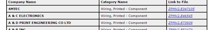
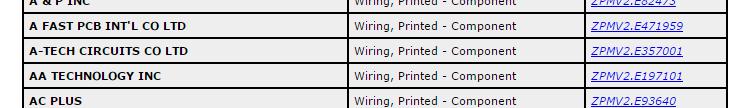
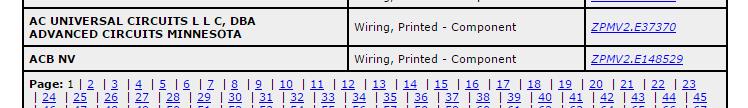
40 Online Certifications Directory Search Results for: UL Category Code = ZPMV2 ZPMV2 is the main UL category code for Recognized PCBs 40
41 Online Certifications Directory 41
42 UL iq Database Accessed by going to iq.ul.com 42
43 UL iq Database 43
44 UL iq Database 44
45 UL iq Database 45
46 UL iq Database Accessed for iq.ul.com 46
47 UL iq Database 47
48 UL iq Database 48
49 Agenda What is UL and what are its aims Drivers for UL PCB Recognition Purpose of UL PCB Requirements Benefits of buying UL Recognized PCBs Types of UL PCB Recognition Elements controlled for a Recognized PCB Where to view UL PCB Recognition Considerations when specifying a PCB that needs to be UL Recognized UL Marking Requirements on the PCB 49
50 So what board do you need? Just saying a board needs to meet UL might not get you want you need or want Could end up with something very different to what you need unless you provide the right details 50
51 Understand What Parameters Your PCB Needs It is important to specify the right PCB when asking for UL Recognition The parameters required for your PCB will be based on the application of the board in your end product May need only a flame rating or could need a flame rating, MOT, DSR compliance and a minimum CTI value If you are not sure what parameters you will need the PCB to have please engage with UL and an end product engineer will be able to help you determine this - Do this as earlier in the design phase as you can 51
52 Parameters to Consider Do You Need a Specific Flame Rating? Minimum acceptable flame class is specified by end-product requirements Classification represents small scale sample evaluation and burn time Flame Classes - V-0, V-1, V-2 - VTM-0, VTM-1, VTM-2 - HB Determined by performing UL94 burning tests on the PCB With and without coatings based on finished PCB After thermal shock (thermal stress) exposure Slide 52
53 The Flame Tests HB Horizontal Burning Most flammable Known as slow-burning materials Generally materials with little or no flame-retardant added Test measures burning rate V Vertical l Burning (20mm) Less flammable Known as self-extinguishing materials Generally have flame-retardant added A measure of the material s ability to extinguish itself once removed from the source of ignition VTM Vertical Thin Material For materials that due to their thinness, either distort, shrink and/or are consumed up to the holding clamp when tested under Vertical Flame Test PCB manufacturer can chose to conduct VTM test if the samples are less that 0.25mm in thickness and can be formed around the mandrel used for testing Slide 53
54 The 20mm Vertical Flame Test Vertically oriented sample Cotton 300 mm 2 - ten second flame applications Observe - flame/glow time - cotton indicator - extent of burn Sample dimensions are 125mm x 13mm x thickness based on product being tested Slide 54
55 The Vertical Thin Material (VTM) Flame Test Front view Side view Back view Sample dimensions are 200mm x 50mm x thickness based on product being tested Slide 55
56 The Flame Ratings Slide 56
57 Parameters to Consider Do You Need a Maximum Operating Temperature (MOT)? Represents PCB maximum continuous use temperature End-product exposure under normal operating conditions Minimum acceptable MOT specified by end-product requirements Cannot exceed base material mechanical or electrical RTI Simulated on PCBs with short-term thermal conditioning (10 or 56 days) Exposure temperature based on PCB manufacturer request MOT determined by analysis of PCB physical properties - Conductor adhesion and PCB delamination Not a property Recognized for Flammability-Only PCB types Slide 57
58 Bond Strength & Delamination Test Samples 10 mm 13 mm Max diameter 50 mm Needs to be within 0.40 A mm from edge of board 0.40 mm B A < 0.40 mm A B B C 100 mm A:Minimum width conductor B:1.60 mm wide conductor C:Edge conductor Slide 58
59 RTI vs. MOT RTI (Relative Thermal Index) - The temperature below which a critical property will not be unacceptably compromised through chemical thermal degradation, over the reasonable life of an electrical product MOT (Maximum Operating Temperature) The maximum continuous use temperature that the PCB may be thermally exposed to under normal operating conditions Slide 59
60 Parameters to Consider Do You Need Direct Support (DSR) Compliance? Direct Support Requirements (DSR) represent performance characteristics for Recognized laminates in direct contact with current carrying parts at 120V or less PCB DSR compliance is determined by the materials available to manufacture it, no tests are done directly on the PCB Not a property p Recognized for Flammability-Only y PCB types A PCB type may be able to be manufactured using materials that are DSR complaint and others that t are not. In this case the PCB will have the DSR triangle documented on the Listing Card. - When a PCB is Recognized with a and a DSR compliant material was used for manufacture then this triangle should also be marked on the board Slide 60
61 DSR Performance Tests Comparative Tracking Index (CTI) Determine spacing requirements with addition of wet contaminant ASTM D3638 test method used for UL Recognition Dielectric i Strength th (DS) Establish insulation resistance baseline at 5000V or 6.89 kv/mm High Current Arc Ignition (HAI) Simulate loose connections and broken leads Hot Wire Ignition (HWI) Determine ignition properties when adjacent to or supporting an insulated or uninsulated wire Slide 61
62 DSR Performance Tests (cont d) Volume Resistivity (VR) Determine if material is an insulator or a semi-conductive material Heat deflection Identify and restrict t the use of low temperature t polymeric materials Not required for thermoset or film materials Slide 62
63 Direct Support ( ) Slide 63
64 Parameters to Consider Do You Need A Minimum i CTI (PLC) Rating? Comparative Tracking Index (CTI) evaluated on laminate materials CTI values are reported on the Listing Card as a Performance Level Category (PLC) ASTM D3638 test method used for UL Recognition Property is not deemed to be thickness dependent Slide 64
65 CTI (PLC) Rating PCB CTI (PLC) values determined by the materials available to manufacture the board, no tests are done directly on the PCB Not a property Recognized for Flammability-Only PCB types A PCB type may be able to be manufactured using materials with different CTI (PLC) values. When this is the case a * will be documented on the Listing Card. - When a PCB is Recognized with a * for the CTI value the CTI value of the material used should be marked on the PCB Slide 65
66 Parameters to Consider What soldering processes will the PCB be exposed to during population? Solder limits represent assembly process - Maximum surface temperature - Cumulative exposure time Simulated on PCB samples with thermal shock (thermal stress) test - Designed to evaluate the physical fatigue of the anticipated assembly soldering temperatures t (solder limits) it Test with maximum temperature and maximum time, or multiple solder limit specified by PCB manufacturer Slide 66
67 Parameters to Consider Multiple Soldering Processes Assembly processes now often use Surface Mount Technology (SMT) - Traditional solder float test t (single time and temp) does not represent industry practices - PCBs exposed to at least three cycles of reflow process One cycle for single-sided; two for double-sided; three for PTH soldering or rework - Multiple solder limits are used to represent the temperature profile during the soldering operation If your PCB will be exposed to multiple reflow cycles you should be specifying a board with multiple solder limits that represent these processes Slide 67
68 Properties to Consider Does the PCB need to have Canadian Recognition? Depending on where the end product will be sold there may be a requirement for the PCB to be both US and Canadian Recognized No additional testing is required to extend Recognition from US to US and Canadian for the PCB A PCB that has both US and Canadian Recognition will be detailed as having both ZPMV2 and ZPMV8 Recognition in the Online Certifications Directory or will have the following mark on the Listing Card from the UL iq directory Slide 68
69 Properties to Consider Does the PCB need to be made using a specific UL/ANSI Material? The UL/ANSI grade of the base materials used to manufacture a PCB are not included on the Listing Card and are confidential to the PCB manufacturer All materials that the PCB manufacturer can use are documented in their UL file NCAB have worked with the PCB manufacturers to gather this information and capture it in an NCAB database, so they can source the appropriate boards Slide 69
70 FR-4 UL/ANSI Material A change to be aware of FR-4 UL/ANSI category of material has been split into two different UL/ANSI grades, FR-4.0 and FR Changes to the FR-4 materials had meant that not all FR-4 s were behaving the same and as such we could no longer consider testing of one representative for another. To allow continuation of the reduced test programs FR-4 had to be split into FR-4.0 and FR-4.1 UL/ANSI type Resin Reinforcement Material FR-4.0 a Brominated Epoxy Continuous filament woven glass fabric FR-4.1 ab Non-Halogenated Epoxy Continuous filament woven glass fabric a Total inorganic filler content equal to 45 percent maximum by weight b Total halogen content equal to 900ppm maximum Bromine or Chlorine and 1500ppm combined Bromine and Chlorine tested in accordance with UL 746E paragraph 8.12 (which references IPC-TM-650 Method ) Slide 70
71 Do you want the board manufactured in a specific country or factory? Each UL PCB file may have one or more manufacturing location detailed in it - Every manufacturer of UL Recognized PCBs has been evaluated by UL and is subject to ongoing surveillance - Each manufacturing location has to apply a factory mark that identifies which location it was made at, if there is the option of using more than one facility in their UL file Manufacturing locations are confidential to the PCB manufacturers UL file and are not shared on the Listing Card The company address provided on the UL Listing Card does not have to be a manufacturing location NCAB understand what documentation needs to be checked to verify the PCB manufacturing facility is UL Recognized to make that t PCB type Slide 71
72 Agenda What is UL and what are its aims Drivers for UL PCB Recognition Purpose of UL PCB Requirements Benefits of buying UL Recognized PCBs Types of UL PCB Recognition Elements controlled for a Recognized PCB Where to view UL PCB Recognition Considerations when specifying a PCB that needs to be UL Recognized UL Marking Requirements on the PCB 72
73 UL Marking Requirements Mandatory Marks Marking Company Identification Factory Identification Optional / Mandatory Mandatory Mandatory Board Type Designation Mandatory Comments This could be the company name, company initials, a trademark, or UL file number. Anything other than the company name or file number needs to be requested as an alternative company marking option by the PCB manufacturer. All marking options are detailed on the Listing Card. If there is more than one manufacturer detailed in the UL file that could have made the board then a factory identification mark should be present. All manufacturer location marks will be detailed in the UL file in the Authorization page. The board type designation must be applied, so the parameters of the board can be identified. The PCB manufacturer defines the name of the PCB. Canadian Recognition Mark If boards have US and Canadian Recognition it is acceptable to apply the joint Recognition mark Mandatory * * Is not applicable to all UL files. Boards must be detailed as having Canadian Recognition for this mark to be applicable for use. All mandatory marks MUST be applied to the PCB where there is sufficient space. UL 796 defines sufficient space as a space at least 2.5 mm (0.1 inch) high and of sufficient length to accommodate the marking. See section 33 of UL 796 for further information. Slide 73
74 UL Marking Requirements Optional Marks Marking Optional / Mandatory Comments US Recognition Mark Optional This mark does not have to be applied to UL Recognized PCBs. It is an optional mark. If you wish it to be applied to the PCBs you purchase this will need to be requested. Direct Support (DSR) Compliance Symbol ( ) If all base materials detailed for a PCB are considered to be DSR compliant then no DSR marking needs to be applied (indicated as "All" on the Listing Card). If a board contains base materials that are both DSR compliant and not DSR compliant then the DSR triangle may be detailed on the board Optional to signify the material used in fabrication was DSR compliant. This mark must not be applied if the base material used for fabrication was not DSR compliant. If DSR compliance is a requirement for the PCB you are purchasing and the board is Recognized with the make sure to request that your board does meet DSR requirements and is marked accordingly. gy Flame Rating CTI (PLC) Value Optional Optional The flame rating of the board designation may be marked on the board. Each board type may only have a single flame rating assigned to it and as such it is not a mandatory mark. The CTI (PLC) rating may be marked on the board. The CTI (PLC) value to be marked is that detailed for the base material used to construct it. If a minimum CTI value is requirement for the PCB you are purchasing and it is Recognized with a CTI value detailed as * make sure to request that your board is marked with the CTI value for the material a used. Slide 74
75 Summary UL Recognition of components is driven by end product safety concerns PCB requirements will be application dependant Understand the requirements your PCB needs to meet before sourcing the board, minimise the chance of problems as early in the design process as possible Ask for the appropriate parameters and marks to be applied to your UL Recognized PCB UL is here to help you! 75
76 THANK YOU.
Safety Concerns with New
 Safety Concerns with New PV Polymeric Materials Crystal Vanderpan Underwriters Laboratories Inc. October 17, 2010 Copyright 1995-2007 Underwriters Laboratories Inc. All rights reserved. No portion of this
ALTIUMLIVE 2018: NAVIGATING THE COMPLEXITIES OF PCB MATERIAL SELECTION
 ALTIUMLIVE 2018: NAVIGATING THE COMPLEXITIES OF PCB MATERIAL SELECTION Chris Hunrath Insulectro, VP of Technology San Diego October 4 Outline 1 PCB Material Overview 2 What is the Dielectric Constant of
Qualification and Performance Specification for Flexible Printed Boards
 Qualification and Performance Specification for Flexible Printed Boards Developed by the Flexible Circuits Performance Specifications Subcommittee (D-12) of the Flexible Circuits Committee (D-10) of IPC
Welcome to Streamline Circuits Lunch & Learn. Design for Reliability & Cost Reduction of Advanced Rigid-Flex/Flex PCB Technology
 Welcome to Streamline Circuits Lunch & Learn Design for Reliability & Cost Reduction of Advanced Rigid-Flex/Flex PCB Technology Accurate PCB data is critical to the tooling process. Here are some key items
Company Overview Markets Products- Capabilities
 Company Overview Markets Products- Capabilities A Simpler way for PCB production. www.purepcb.co.uk What can Pure do for you? From 1 off Circuit upward, No MOQ/MOV High Mix Production Focus. Fast Turn
IPC-AJ-820A Assembly and Joining Handbook. The How and Why of All Things PCB & PCA
 IPC-AJ-820A Assembly and Joining Handbook The How and Why of All Things PCB & PCA 1 Scope To provide guidelines and supporting info for the mfg of electronic equipment To explain the HOW TO and WHY Discussions
Qualification and Performance Specification for High Frequency (Microwave) Printed Boards
 Printed Boards") Qualification and Performance Specification for High Frequency (Microwave) Printed Boards Developed by the High Speed/High Frequency Board Performance Subcommittee (D-22) of the High Speed/High Frequency
Qualification and Performance Specification for High Frequency (Microwave) Printed Boards Developed by the High Speed/High Frequency Board Performance Subcommittee (D-22) of the High Speed/High Frequency
Trends and Developments
 Trends and Developments Monique Mayr Monique.Mayr@eu.panasonic.com European R&M Group Panasonic Corporation Electronic Material Business Division Weitere Informationen finden Sie auch auf: http://www3.panasonic.biz/em/pcbm/en/index.html
Building HDI Structures using Thin Films and Low Temperature Sintering Paste
 Building HDI Structures using Thin Films and Low Temperature Sintering Paste Catherine Shearer, James Haley and Chris Hunrath Ormet Circuits Inc. - Integral Technology California, USA chunrath@integral-hdi.com
DURAVER -E-Cu quality 104 ML
 J B-DE 104 ML DURAVER -E-Cu quality 104 ML Base materials for multilayers 2 Quality and security to give you the edge The demands imposed with regard to the performance of circuit boards are rising constantly,
Manufacturing Capacity
 Capability List Manufacturing Capacity QTA & Prototype Layer : 1L ~32 L Impedance Board Ball Grid Array ( BGA ) Blind/ Buried Via Micro Via ( Laser Drilling) Flex /Rigid Flexible PCB Series Orders Layer
Interconnection Reliability of HDI Printed Wiring Boards
 Presented in the ECWC 10 Conference at IPC Printed Circuits Expo, SMEMA Council APEX and Designers Summit 05 Interconnection Reliability of HDI Printed Wiring Boards Tatsuo Suzuki Nec Toppan Circuit Solutions,
Specification for Base Materials for Rigid and Multilayer Printed Boards
 ASSOCIATION CONNECTING ELECTRONICS INDUSTRIES Specification for Base Materials for Rigid and Multilayer Printed Boards Developed by the Laminate/Prepreg Materials Subcommittee (3-11) of the Printed Board
B-IS400 IS420/3 IS400 IS420 PCL370HR. Temperature resistant mid and high T g - base materials with low z-axis expansion CAF ENHANCED
 J B-IS4 IS42/3 IS4 IS42 PCL37HR Temperature resistant mid and high T g - base materials with low z-axis expansion CAF ENHANCED Temperature-resistant base materials with low z-axis expansion IS4, IS42 and
TEST REPORT (Self-Tested Data)
") TEST REPORT (Self-Tested Data) CLIENT: IPC Validation Services 3000 Lakeside Drive Suite 105N Bannockburn, IL 60015 USA Attention: Mr. Randy Cherry +1-847-597-5606 TEST ITEMS: Peel Strength, Volume Resistivity,
TEST REPORT (Self-Tested Data) CLIENT: IPC Validation Services 3000 Lakeside Drive Suite 105N Bannockburn, IL 60015 USA Attention: Mr. Randy Cherry +1-847-597-5606 TEST ITEMS: Peel Strength, Volume Resistivity,
Flex and Rigid-Flex Printed Circuit Design
 Flex and Rigid-Flex Printed Circuit Design Old Content - visit altium.com/documentation Modified by on 29-Nov-2016 Related Videos Bending Lines Enhanced Layer Stack Management Layer Stack Regions A rigid-flex
ATS Document Cover Page
 221-008 Item Rev Status: RELEASED printed 9/20/2017 2:27:42 PM by Les Deenin ATS: OPERATIN PROCEDURE ATS Document Cover Page Responsible Department: Supply Chain This copy is uncontrolled unless otherwise
New Developments in PCB Laminates. Dean Hattula, John Coonrod Rogers Corporation Advanced Circuit Materials Division
 New Developments in PCB Laminates Dean Hattula, John Coonrod Rogers Corporation Advanced Circuit Materials Division Overview PCB laminate properties Thermal stability Electrical performance Summary PCB
Lead-Free HASL: Balancing Benefits and Risks for IBM Server and Storage Hardware
 Lead-Free HASL: Balancing Benefits and Risks for IBM Server and Storage Hardware November 19, 2009 M.Kelly, P.Eng, MBA Senior Engineer, ECAT Interconnect Technology Lead-Free Server Development Core Team
!"#$#%&#'(() ) **+,-./01)2-,-.3)456,1) /0! **)
 ) **+,-./01)2-,-.3)456,1) /0! **)") !"#$#%&#'(() ) **+,-./01)2-,-.3)456,1) /0!7.5853-09**) B 2 IT is a Toshiba Process Technology 1. Conductive Ag bumps are printed on a sheet of Cu foil. 2. Prepreg is pierced through by the bumps 3. Another
!"#$#%&#'(() ) **+,-./01)2-,-.3)456,1) /0!7.5853-09**) B 2 IT is a Toshiba Process Technology 1. Conductive Ag bumps are printed on a sheet of Cu foil. 2. Prepreg is pierced through by the bumps 3. Another
IPC A Guideline for Defining "Low- Halogen" Electronic Products. Working Draft. IPC-4903 August August 2010
 IPC-4903 A Guideline for Defining "Low- Halogen" Electronic Products Working Draft August 2010 IPC-4903 August 2010 3000 Lakeside Drive Bannockburn, IL 60015-1249 Tel: 847-615-7100 Fax: 847-615-7105 www.ipc.org
Implementation of IECQ Capability Approval using the IPC-6010 series of Standards
 Page 1 of 13 INTERNATIONAL ELECTROTECHNICAL COMMISSION QUALITY ASSESSMENT SYSTEM FOR ELECTRONIC COMPONENTS (IECQ) DOCUMENT NUMBER: OD 301 DOCUMENT TYPE: Operational Document VERSION: Version 1 TITLE: Implementation
PCB Production Process HOW TO PRODUCE A PRINTED CIRCUIT BOARD
 NCAB Group Seminars PCB Production Process HOW TO PRODUCE A PRINTED CIRCUIT BOARD NCAB GROUP PCB Production Process Introduction to Multilayer PCBs 2 Introduction to multilayer PCB s What is a multilayer
The Anatomy of a PCB SINGLE-SIDED BOARD
 Published on Online Documentation for Altium Products (https://www.altium.com/documentation) 主页 > The Board Using Altium Documentation Modified by Jason Howie on Apr 11, 2017 Open up just about any electronic
Bending Impacts Layers
 Designing for Flexibility and Reliability Understanding factors that contribute to the reliability of a flex circuit that is formed or repeatedly flexed The name "flexible circuit" sums up the function
==========qéåüåáå~ä=ç~í~=^h^cibu h`i=eq = =
 qéåüåáå~äç~í~^h^cibu h`ieq ^h^cibu h`ieqw `çéééêä~ãáå~íéëçå~éçäóáãáçéjñáäãä~åâáåö ÑçêÑäÉñáÄäÉéêáåíÉÇÅáêÅìáíë qüé^h^cibu h`ieqéêçöê~ããé AKAFLEX KCL HT is available from KREMPEL as two-layer laminates and
Verifying The Reliability Of Connections In HDI PWBs
 Verifying The Reliability Of Connections In HDI PWBs The stacking of via holes is used effectively in the development of high density circuits on build-up printed wiring boards (PWBs). However, when micro
B-DE104. DURAVER -E-Cu quality 104 quality 104 KF quality 104 TS
 J B-DE104 DURAVER -E-Cu quality 104 quality 104 KF quality 104 TS Epoxy fibre glass laminate (FR-4) Circuit boards for computers, communications systems, industrial electronics and electronic devices in
Interconnection Evaluation Technology for Printed Wiring Boards
 Interconnection Evaluation Technology for Printed Wiring Boards Mitsuhiko Sugane Yoshihiro Morita (Manuscript received December 28, 2009) As a developer of world-class products including server and network
A NOVEL APPROACH TO MANAGE THE
 A NOVEL APPROACH TO MANAGE THE IMPLEMENTATION OF MORE SUSTAINABLE FLAME RETARDANTS Presented by Marshall Moore Director, Technology, Advocacy & Marketing Fire Retardants in Plastics 2013 June 13-14 Denver,
c/bach, 2-B Pol. Ind Foinvasa Montcada i Reixac (Barcelona) SPAIN Tel FAX
 SPAIN Tel FAX") 1- What is 2- How does it work? 3- How do we make it? 4- Applications 5- Processing? WHAT IS? Thick aluminium based substrate, cladded in ED copper foil. Designed for an effective thermal dissipation and
1- What is 2- How does it work? 3- How do we make it? 4- Applications 5- Processing? WHAT IS? Thick aluminium based substrate, cladded in ED copper foil. Designed for an effective thermal dissipation and
Axiom Electronics LLC
 1 of 8 1.0 PURPOSE and SCOPE This document defines Axiom s requirements for printed circuit board (PCB) fabrication, handling, and storage. Industry standards are referenced where appropriate. This document
Question: Are RO4000 materials compatible with lead-free processes? Answer:
 Question: Are RO4 materials compatible with lead-free processes? Answer: RO4 cores and prepregs are among the most temperature stable products available. They easily meet or exceed all expectations for
IPC Qualification and Performance Specification for Organic Multichip Module (MCM-L) Mounting and Interconnecting Structures IPC-6015
 Mounting and Interconnecting Structures IPC-6015") ASSOCIATION CONNECTING ELECTRONICS INDUSTRIES Qualification and Performance Specification for Organic Multichip Module (MCM-L) Mounting and Interconnecting Structures February 1998 A standard developed
ASSOCIATION CONNECTING ELECTRONICS INDUSTRIES Qualification and Performance Specification for Organic Multichip Module (MCM-L) Mounting and Interconnecting Structures February 1998 A standard developed
A Novel Material for High Layer Count and High Reliability Printed Circuit Boards
 A Novel Material for High Layer Count and High Reliability Printed Circuit Boards Jie Wan, Junqi Tang, Xianping Zeng Shengyi Technology Co., Ltd. No.5 Western Industry Road, North Industry District SSL
High Frequency Circuit Materials Attributes John Coonrod, Rogers Corporation
 High Frequency Circuit Materials Attributes John Coonrod, Rogers Corporation Specialty high frequency circuit materials have been used in the PCB industry for decades and for many different reasons. There
ESPANEX L Series. Technical data sheet Nishigotanda Shinagawa Tokyo, , Japan TEL FAX
 ESPANEX L Series Technical data sheet This sheet will be changed without any information in advance. The data on this sheet are solely for your reference and are not to be constructed as constituting a
Flexible Printed Circuits Design Guide
 www.tech-etch.com/flex Flexible Printed Circuits Design Guide Multilayer SMT Assembly Selective Plating of Gold & Tin-Lead Fine Line Microvias Cantilevered & Windowed Leads 1 MATERIALS CONDUCTOR Copper
Fixed Resistors INSULATED ALUMINUM SUBSTRATES. Thermal Solutions for Hi Brightness LED Applications - Application Note
 INSULATED ALUMINUM SUBSTRATES TT electronics is a leading designer and manufacturer of electronic components. As a result of our experience with power components, Anotherm substrates were developed as
NP-180R NAN YA PLASTICS CORPORATION ELECTRONIC MATERIALS DIVISION. COPPER CLAD LAMINATE DEPARTMENT NO TUNG HWA N. ROAD, TAIPEI, TAIWAN.
 New: 2014/04/30 flame retardant copper clad laminate NP-180R High Tg 175 (DSC) Excellent dimensional stability through-hole reliability Excellent electrical, chemical and heat resistance properties IPC-4101C
IMPACT OF MICROVIA-IN-PAD DESIGN ON VOID FORMATION
 IMPACT OF MICROVIA-IN-PAD DESIGN ON VOID FORMATION Frank Grano, Felix Bruno Huntsville, AL Dana Korf, Eamon O Keeffe San Jose, CA Cheryl Kelley Salem, NH Joint Paper by Sanmina-SCI Corporation EMS, GTS
PEC (Printed Electronic Circuit) process for LED interconnection
 process for LED interconnection") PEC (Printed Electronic Circuit) process for LED interconnection Higher wattage LED s/ power components or their placement in higher densities, requires a larger dissipation of heat in a more effective
PEC (Printed Electronic Circuit) process for LED interconnection Higher wattage LED s/ power components or their placement in higher densities, requires a larger dissipation of heat in a more effective
ALTIUMLIVE 2018: FLEX: SOMETHING NEW FOR EVERYONE
 ALTIUMLIVE 2018: FLEX: SOMETHING NEW FOR EVERYONE Tara Dunn Omni PCB President San Diego October 5, 2018 Applications That Span Technology Today s Discussion: 1. Basic processing steps for both subtractive
Boards: Get the Bare Facts on Bare Boards
 Welcome to the EPTAC Webinar Series: Boards: Get the Bare Facts on Bare Boards You are connected to our live presentation delivered via the internet. The webinar will begin shortly. You will see the presentation
FLEXIBLE & RIGID-FLEX CIRCUITS TECHNICAL ENGINEERING GUIDE. Delivering Quality Since 1952.
 FLEXIBLE & RIGID-FLEX CIRCUITS TECHNICAL ENGINEERING GUIDE Delivering Quality Since 1952. DELIVERING QUALITY SINCE 1952. Epec Engineered Technologies designs and manufactures customized, built-to-print,
: GA-170-LL/ GA-170B-LL
 Grace Electron Corp. Processing Guide Phenolic Cured Material Laminate/ Prepreg : GA-170-LL/ GA-170B-LL Grace Electron Corp. Tech. & QA Dept. Revision 2010/6/14 Page 1 of 6 @2010Grace Group Grace Declaration:
PCB Fabrication Specification
 Original Author: Steve Babiuch Process Owner: Steve Babiuch Page 2 of 8 1.0 Purpose This specification establishes the NEO Tech fabrication requirements for printed circuit boards. The order of precedence
Long Term Thermal Reliability of Printed Circuit Board Materials
 Long Term Thermal Reliability of Printed Circuit Board Materials Eva McDermott, Ph.D., Bob McGrath, and Christine Harrington Amphenol Printed Circuit Board Technology Nashua, NH 03062 Abstract This paper
Sherlock 4.0 and Printed Circuit Boards
 Sherlock 4.0 and Printed Circuit Boards DfR Solutions January 22, 2015 Presented by: Dr. Nathan Blattau Senior Vice President 9000 Virginia Manor Rd Ste 290, Beltsville MD 20705 301-474-0607 www.dfrsolutions.com
All-Polyimide Thermal Interface Products
 All-Polyimide Thermal Interface Products SMTA Harsh Environment Electronics Workshop Dearborn, MI 6/24/03 Jim Fraivillig Fraivillig Technologies Boston, MA Why polyimide? HARSH ENVIRONMENT ELECTRONICS.
Accreditation Scope by Certification Test Order
 Organization NEMA MW 1000 NEMA RE-2 Section 4.11 ASTM D149 ASTM D150 ASTM D256 ASTM D257 ASTM D495 ASTM D570 ASTM D635 ASTM D638 ASTM D790 ASTM D882 ASTM D1653 ASTM D1676 ASTM D1822 ASTM D1830 ASTM D1876
TECHNICAL DATA SHEET 1 P a g e Revised January 9, 2014
 1 P age Revised January 9, 2014 TAIYO PSR-4000 CC01SE (UL Name: PSR-4000JV / CA-40JV) LIQUID PHOTOIMAGEABLE CURTAIN COAT SOLDER MASK Curtain Coat Application Aqueous Developing Solder Mask RoHS Compliant
: GA-HF-14/ GA-HFB-14
 Grace Electron Corp. Processing Guide Halogen Free Material Laminate/ Prepreg : GA-HF-14/ GA-HFB-14 Grace Electron Corp. Tech. & QA Dept. Revision 2009/5/18 Page 1 of 7 @2009Grace Group Grace Declaration:
FABRICATING HIGH CURRENT, HEAVY COPPER PCBS
 Royal Circuit Solutions 21 Hamilton Ct, Hollister, CA 95023 (831) 636-7728 www.royalcircuits.com FABRICATING HIGH CURRENT, HEAVY COPPER PCBS INTRODUCTION All printed circuit boards (PCBs) carry current
PSR-4000 HFX Satin Colors (UL Name: PSR-4000DE / CA-40HF)
") PSR-4000 HFX Satin Colors (UL Name: PSR-4000DE / CA-40HF) LIQUID PHOTOIMAGEABLE SOLDER MASK Application by Screen Printing Available in Black, Blue, Clear, Red and White Satin Finish All Colors are Halogen-Free
PSR-4000 HFX Satin Colors (UL Name: PSR-4000DE / CA-40HF) LIQUID PHOTOIMAGEABLE SOLDER MASK Application by Screen Printing Available in Black, Blue, Clear, Red and White Satin Finish All Colors are Halogen-Free
Phosphinates, the Flame Retardants for Polymers in Electronics. Public Dr. S. Hörold Development Flame Retardants ATPG
 FR Polymers in the E&E Industry Demanding requirements Slide 2 Material properties (selection) small parts, thin wall, low density Surface Mount Technology lead free soldering laser markability / weldability
Lead Free Assembly: A Practical Tool For Laminate Materials Selection
 Lead Free Assembly: A Practical Tool For Laminate Materials Selection Erik J. Bergum David Humby Isola Abstract: The impending European RoHS legislation, restricting the use of lead containing solders,
VT-45PP VT-47PP VT-447PP
 & Prepreg General Information Ventec provides a series of and Prepregs with different glass style and resin content. These products have good bonding and thermal performance in applications of heat sink
IPC-6012DA with Amendment 1. Automotive Applications Addendum to IPC-6012D Qualification and Performance Specification for Rigid Printed Boards
 A with Amendment 1 Automotive Applications Addendum to Qualification and Performance Specification for Rigid s FINAL DRAFT FOR INDUSTRY REVIEW MAY 2018 0.1 Scope This addendum provides requirements to
TENDER NO. PGVCL/PROC/HT SMC Meter Box/872
 TECHNICAL SPECIFICATION FOR HT AMR METER BOXES MADE FROM GLASS REINFORCED POLYSTER SHEET MOULDING COMPOUNDS (SMC). 1.0 SCOPE: 1.1 This specification covers the design, manufacturing and testing of anticorrosive,
B-IS620i/3. IS620i. Base material. for high-frequency. applications CAF. Enhanced
 J B-/3 Base material for high-frequency applications CAF Enhanced Low loss base material with a stable dielectric behaviour over frequency is a base material for high frequency applications, especially
NCAB Group PCB Specification
 NCAB Group Seminar no. 9 NCAB Group PCB Specification NCAB GROUP NCAB Group PCB Specification 14 key features for durable and reliable PCB s NCAB GROUP NCAB Group PCB Specification 2 Are all PCB s created
Modeling Printed Circuit Boards with Sherlock 3.2
 Modeling Printed Circuit Boards with Sherlock 3.2 DfR Solutions September 23, 2014 Presented by: Dr. Nathan Blattau Senior Vice President 9000 Virginia Manor Rd Ste 290, Beltsville MD 20705 301-474-0607
ELECTRONIC POTTING & ENCAPSULATING COMPOUNDS
 ELECTRONIC POTTING & ENCAPSULATING COMPOUNDS Epoxies Product UL Recognized Mix Ratio by Weight Mix Ratio by Volume Mixed Viscosity @ 25 C (in cps) Gel Time @25 C Glass Transition Temp. (Tg) 0155 No 1 Component
Annular Ring and Feature Clearances. Track to Feature Clearances
 Hi-Tech Corporation Technical Capabilities Annular Ring and Feature Clearances Outer Value layer min (mm) A 75 B 125 C 150 Inner Value layer min (mm) A 100 B 150 C 150 Track to Feature Clearances Outer
3M Electromagnetic Compatible Products
 3M Electromagnetic Compatible Products 3Innovation Faster, smaller, lighter, easier the skyrocketing development of today s electronics requires new solutions for significant new problems. These solutions
AISMALIBARR COBRITHERM R IGAV
 AISMALIBA COBITHEM IGAV AISMALIBA AISMALIBA started in the winding wire production in 1934, becoming one of the biggest European wiring companies in the world. Several years later, the company entered
IPC-6013A Amendment 2
 ASSOCIATION CONNECTING ELECTRONICS INDUSTRIES IPC-6013A Amendment 2 Qualification and Performance Specification for Flexible Printed Boards IPC-6013A Amendment 2 March 2006 A standard developed by IPC
The Pros of Conformal Coatings
 The Pros of Conformal Coatings Choosing the right coating to preserve and protect electronics in harsh environments Introduction Many chemicals found in the oil, gas, and petrochemical industries can consign
Welcome to the KEMET Ceramic Capacitor Flex Crack Mitigation product training module. This module will review sources of stress in surface mount
 1 Welcome to the KEMET Ceramic Capacitor Flex Crack Mitigation product training module. This module will review sources of stress in surface mount multilayer ceramic capacitors, provide board layout recommendations,
Deepen your knowledge
 FLEX & RIGID-FLEX PRINTED CIRCUIT BOARDS Deepen your knowledge What are Flex & Rigid-flex Printed Circuit Boards? What are their similarities and differences? Their capabilities? And the design rules.
Space product assurance
 ECSS-Q-ST-70-10C Space product assurance Qualification of printed circuit boards ECSS Secretariat ESA-ESTEC Requirements & Standards Division Noordwijk, The Netherlands Foreword This Standard is one of
Flex-Rigid Design Guide
 DESIGN GUIDE Version 1.2 / March 2018 Flex-Rigid Design Guide The trend to miniaturization in electronics continues. Integrated circuit board solutions are becoming more and more popular as a means of
mtc an acal group company Thermally Conductive Products
 mtc MTC About us Features MODERN COMPANY WITH LONG TRADITION MTC is specialized on the protection of electronic circuits and the environment from high frequency electromagnetic radiation. Therefore we
GRAPHIC MANUFACTURING CAPABILITY Q217-18
 All features are design dependent and may not be achievable in combination Reduced Yield / Special values up ( or down ) to the standard limit are design and application dependent Standard features only
PRINTED CIRCUITS HANDBOOK
 PRINTED CIRCUITS HANDBOOK Clyde F. Coombs, Jr. Sixth Edition Me Graw New York Chicago San Francisco Lisbon London Madrid Mexico City Milan New Delhi San Juan Seoul Singapore Sydney Toronto CONTENTS List
TECHNYL C 50H2 NATURAL
 TECHNYL C 50H2 NATURAL Description TECHNYL C 50H2 Natural is a unreinforced melamine cyanurate flame retarded polyamide 6. This product is heat stabilised and can be used for injection moulding and extrusion
Environment-friendly Halogen-free Materials for PWBs
 Environment-friendly Halogen-free Materials for PWBs Yoshiyuki Takeda*/Kenichi Ikeda*/Nozomu Takano** *R & D Group, Electronic Laminates Div., Hitachi Chemical Co., Ltd. **Research & Development Center,
NF-2000 NF-2000M08 NF-2000VUNS2 N-7S
 POLYCARBONATE RESIN SHEET & FILM INDUSTRIAL APPLICATIONS GENERAL GRADE Polycarbonate Sheet NF-2000 NF-2000M08 NF-2000VUNS2 N-7S Polycarbonate Film FE-2000 FE-2000M01 FE-2000M12 FE-2000N-7 Polycarbonate
High Tg Bromine-free Laminates for PWB Applications
 Presented at IPC Printed Circuits EXPO www.ipcprintedcircuitexpo.org High Tg Bromine-free Laminates for PWB Applications Marty Choate Isola Abstract The development of halogen free materials has been a
ESA s approach to quality control of the supply chain for PCBs. Stan Heltzel European Space Agency
 ESA s approach to quality control of the supply chain for PCBs Stan Heltzel European Space Agency Outline A. ESA s approach to supply chain control for PCBs B. Case study: contamination in PCBs 1. Problem
Last Updated: August, / 5
 Vydyne 21SPF is a general-purpose PA66 resin. Available in natural, it is designed principally for injection-molding fabrication. This grades offer a well-balanced combination of engineering properties
Valox* Resin V3900WX Asia Pacific: COMMERCIAL
 PBT/PC blend - Unreinforced - Flame Retardant. This is a UV-stabilized grade designed for outdoor enclosure applications requiring UL 746C F1 weatherability performance. MECHANICAL Tensile Stress, yield
ROLINX Laminated Busbar. Design Rules Version 01 (12/2015)
") ROLINX Laminated Busbar Design Rules Version 01 (12/2015) Content 1. Introduction... 03 7. Features... 13 2. Configuration...03 8. Thermal parameters... 14 3. Products... 04 9. General parameters... 14
ROLINX Laminated Busbar Design Rules Version 01 (12/2015) Content 1. Introduction... 03 7. Features... 13 2. Configuration...03 8. Thermal parameters... 14 3. Products... 04 9. General parameters... 14
IPC -7095C Design and Assembly Process Implementation For BGAs
 IPC -7095C Design and Assembly Process Implementation For BGAs 1 Overview With the introduction of BGA components, things had to change: New design New assembly process New repair process New inspection
When a standard or other referenced document referred to in this specification is superseded by an approved revision, the revision shall apply.
 I. References When a standard or other referenced document referred to in this specification is superseded by an approved revision, the revision shall apply. II. Listing The conduit shall be listed by
(13) PCB fabrication / (2) Focused assembly
 PCB fabrication / (2) Focused assembly") Company Fact Sheet TTM Technologies, Inc. is a world-wide leader in the manufacture of technologically advanced PCBs, backplane and sub-system assemblies. Our Global Presence / Local Knowledge approach
Company Fact Sheet TTM Technologies, Inc. is a world-wide leader in the manufacture of technologically advanced PCBs, backplane and sub-system assemblies. Our Global Presence / Local Knowledge approach
Troubleshooting. for. Printed Board. Manufacture. and Assembly IPC PE-740. Revision A December Developed by THE INSTITUTE FOR INTERCONNECTING
 IPC PE-740 Revision A December 1997 Troubleshooting for Printed Board Manufacture and Assembly IPC 1997 Developed by THE INSTITUTE FOR INTERCONNECTING AND PACKAGING ELECTRONIC CIRCUITS December 1997 IPC-PE-740
ICDs (InterConnect Defects) What are they? Where do they come from? How can we make them go away? Doug Trobough Suixin Zhang
 What are they? Where do they come from? How can we make them go away? Doug Trobough Suixin Zhang") ICDs (InterConnect Defects) What are they? Where do they come from? How can we make them go away? Doug Trobough Suixin Zhang Definition of ICD ICDs are any defect that occurs adjacent to the innerlayer
ICDs (InterConnect Defects) What are they? Where do they come from? How can we make them go away? Doug Trobough Suixin Zhang Definition of ICD ICDs are any defect that occurs adjacent to the innerlayer
10 Manor Parkway, Suite C Salem, New Hampshire
 Micro-Precision Technologies (MPT) is an independent manufacturer of hybrid integrated circuits, multichip modules, and high-precision thick film substrates for the military, medical, avionics, optoelectronics,
SECTION FIBERGLASS REINFORCED PLASTIC (FRP) DOORS AND FIBERGLASS RESIN TRANSFER MOLDED DOOR FRAMES
 DOORS AND FIBERGLASS RESIN TRANSFER MOLDED DOOR FRAMES") SECTION 08220 FIBERGLASS REINFORCED PLASTIC (FRP) DOORS AND FIBERGLASS RESIN TRANSFER MOLDED DOOR FRAMES FIB-R-MAX SINGLE 3070 DOOR FIRE RATED SERIES MEETING UL 10(C) POSITIVE PRESSURE AND UL 10(B) NEGATIVE
SECTION 08220 FIBERGLASS REINFORCED PLASTIC (FRP) DOORS AND FIBERGLASS RESIN TRANSFER MOLDED DOOR FRAMES FIB-R-MAX SINGLE 3070 DOOR FIRE RATED SERIES MEETING UL 10(C) POSITIVE PRESSURE AND UL 10(B) NEGATIVE
A3X2G7. Product Information Ultramid 07/2015 PA66-GF35 FR. BASF SE Ludwigshafen, Germany
 Product Information Ultramid A3X2G7 07/2015 PA66-GF35 FR Product description A glass fibre reinforced injection moulding grade with improved flame retardance. Flame retardant based on red phosphorus; giving
: GA-170-LE/ GA-170B-LE
 Grace Electron Corp. Processing Guide Phenolic Cured Material Laminate/ Prepreg : GA-170-LE/ GA-170B-LE Grace Electron Corp. Tech. & QA Dept. Revision 2010/3/30 Page 1 of 7 @2010Grace Group Grace Declaration:
An Assessment of the Impact of Lead-Free Assembly Processes on Base Material and PCB Reliability
 An Assessment of the Impact of Lead-Free Assembly Processes on Base Material and PCB Reliability Edward Kelley Isola Abstract Environmental regulations are forcing the elimination of lead (Pb) from electronic
SCOPE OF ACCREDITATIONTO ISO/IEC 17025:2005
 SCOPE OF ACCREDITATIONTO ISO/IEC 17025:2005 LYDALL THERMAL / ACOUSTICAL GROUP MATERIAL TESTING LABORATORIES 1241 Buck Shoals Road Hamptonville, NC 27020 Mr. Bill Hammond Phone: 336 355 1507 MECHANICAL
SCOPE OF ACCREDITATIONTO ISO/IEC 17025:2005
 SCOPE OF ACCREDITATIONTO ISO/IEC 17025:2005 LYDALL THERMAL / ACOUSTICAL GROUP MATERIAL TESTING LABORATORIES 1241 Buck Shoals Road Hamptonville, NC 27020 Mr. Shane Jolly Phone: 336 468 8598 MECHANICAL Valid
Sn-Pb plating or Tin plating
 2/14 Unit mm L a a Code letter Dimension L 2..2 W 1.25.2 W t a b.4.1.4.2.4.2 t b b Fig.1 Construction and dimensions NOTE : Resistive element Electrode Protective coat Substrate Nichrome alloy thin film