SERVICE ENTRANCE SPECIFICATIONS FOR RESIDENTIAL AND COMMERCIAL
|
|
|
- Basil Young
- 6 years ago
- Views:
Transcription

1 SERVICE ENTRANCE SPECIFICATIONS FOR RESIDENTIAL AND COMMERCIAL AMPERES AT SINGLE-PHASE, 3 WIRE THREE-PHASE, 4 WIRE 120/240 VOLTS 120/240 VOLTS * 240/480 VOLTS 277/480 VOLTS Y 120/208 VOLTS 120/208 VOLTS Y *NOT AVAILABLE FROM UNDERGROUND PRIMARY SYSTEMS 10/28/2009
2 DESCRIPTION TABLE OF CONTENTS LIST OF ILLUSTRATIONS PAGE i iii SECTION 100. GENERAL NOTES 1 General Rules and Recommendations SECTION 200. EXCAVATION AND CIVIL WORK Trenching Notes 2.1 Backfill Specifications SECTION 300. SAFETY AND ACCESS CONSIDERATIONS Clearances 3.1 Service Entrance and Meter Locations SECTION 400. SERVICE DISCONNECTS AND METERING Commercial and Residential Services Amps 4.1 Service Disconnect Amps 4.2 Meter Socket and Metering Amps 4.3 Residential and Commercial Services 201 TO 400 Amps Main Service Disconnect Metering for Services Amps 4.4 Single-phase 320 AMP Meter/main for Underground Installations 4.5 Commercial and Residential Services Amps Main Service Disconnect Metering for Services Amperes 4.6 Commercial and Residential Services Amps Main Service Disconnect Metering for Services Amps 4.7 Multiple Metered Installations SECTION 500. SERVICE CONDUIT AND CONDUCTORS Service Conduit (Overhead Services) 5.1 Service Lateral Riser Conduit (Underground Services) 5.2 Service Entrance Conductors Overhead Service Entrance Conductors 5.3 Service Lateral Conductors (Underground Services) SECTION 600. SERVICE BONDING AND GROUNDING Service Bonding 6.1 Grounding Electrode Conductor 6.2 Grounding Electrode 10/28/2009 i
3 SECTION 700. MOUNTING AND FASTENING 75 SECTION 800. TEMPORARY SERVICES 76 SECTION 900 FAULT CURRENTS 78 SECTION MOTOR START REQUIREMENTS Protection of Motors and Other Equipment 10.3 Voltage Fluctuation Limits 10.4 Motor Starting Variables 10.5 Frequency Drives & 1Ø to 3Ø Converter Requirements 10.6 Air-Conditioning Units(Compressor Motors) 10.7 Service Entrance Requirements for Motor Loads SECTION CO-GENERATION AND UTILITY INTERCONNECTION Types of Installations 11.2 Installation Procedure Summaries 10/28/2009 ii
4 LIST OF ILLUSTRATIONS AND TABLES FIGURE PAGE JOINT TRENCH CONDUIT AND SWEEP APPLICATIONS HILL HOLDER BARRIER POST CONDUIT STUB DETAIL THREE-PHASE RISER (3 RISERS) SINGLE-PHASE RISER THREE-PHASE RISER (6 INCH) RESIDENTIAL SERVICE RISER CONCRETE CAP DETAIL SHALLOW TRENCH CONDUIT ENCASEMENT DETAIL TYPICAL ROAD CROSS SECTION TRANSFORMER PAD DETAIL KVA TRANSFORMER PAD DETAIL KVA SINGLE-PHASE TRANSFORMER PAD & CONDUIT DETAIL SINGLE-PHASE SWITCH PAD & CONDUIT DETAIL THREE-PHASE TRANSFORMER PAD & CONDUIT DETAIL THREE-PHASE SWITCH PAD & CONDUIT DETAIL SECONDARY PEDESTAL CONDUIT DETAIL STAKING DETAIL STREETLIGHT DETAIL SAFE WORKING CLEARANCES OVERHEAD LINES WORKING CLEARANCES PAD-MOUNT EQUIPMENT WORKING CLEARANCE SERVICE ENTRANCE ELECTRIC AND GAS METER SEPARATION METER LOCATIONS A METER/MAIN COMBINATION POLE-MOUNTED OVERHEAD SERVICE OVERHEAD METER/MAIN ON WALL UNDERGROUND METER/MAIN ON WALL METER PEDESTAL METER PEDESTAL HIGHWAY INSTALLATION METER PEDESTAL NOTES SINGLE-PHASE COMMERCIAL WITH TEST BLOCK BYPASS THREE-PHASE COMMERCIAL WITH LEVER BYPASS METER BASE APPLICATIONS AMP WALL-MOUNTED CT CAN AMP METER/MAIN UNDERGROUND AMP METER/MAIN OVERHEAD AMP CT CAN ON FABRICATED PANEL--UG AMP CT CAN ON FABRICATED PANEL OH 56 10/28/2009 iii
5 FIGURE PAGE AMP FREE-STANDING SES FREE-STANDING SES WITH REMOTE METER AND SHUNT SHUNT TRIP WIRING SCHEMATIC WALL-MOUNTED SIX OR LESS MULTIPLE-METERS FREE-STANDING MULTIPLE-METERS COLD-SEQUENCE FREE-STANDING OVER SIX MULTIPLE-METERS OVERHEAD SERVICE ATTACHMENT DETAIL RESIDENTIAL WIRE TABLE TEMPORARY UNDERGROUND SERVICE MINIMUM FAULT CURRENT TABLE MANUAL ISOLATION TRANSFER SWITCH 86 10/28/2009 iv
6 SECTION 100. GENERAL NOTES 1.0 General Rules and Recommendations 1.1. The scope of this specification has been expanded to include more information regarding the excavation, conduit placement, and utility cabinet installation of underground primary and secondary distribution systems provided by homeowners, contractors, and developers where that work will necessarily interface with that of SSVEC Line extensions may include primary and secondary lines, as well as services, and may be aerial (overhead) lines, underground lines, or a combination of any of these configurations. Routing and construction configurations of power lines will be worked out with the customer through the guidance and direction provided by SSVEC line extension personnel. The customer is responsible for all costs associated with new line extensions, except any part of the work that may be deemed for the exclusive benefit of SSVEC. This will be determined at the sole discretion of SSVEC Poles and other equipment for SSVEC overhead extensions are installed exclusively by SSVEC crews. For underground installations, unless otherwise directed by SSVEC, the customer will be responsible for excavations and other civil work. The customer is responsible for supplying and installing all PVC conduit unless otherwise directed by SSVEC personnel. This specification is intended to be helpful in detailing the customer s responsibilities It is the intention of this specification to insure the workmanship and materials of all service entrances, meet or exceed the requirements of the National Electrical Code (NEC--2008) and the National Electric Safety Code (NESC--2007). Any item not specifically mentioned in this specification shall meet or exceed the requirements of these two codes. Specified equipment shall be manufactured according to Electric Utility Service Entrance Requirements Committee (EUSERC) Standards or, if no EUSERC standard exists, then the equipment shall be listed by a nationally recognized testing laboratory (e.g. UL) and shall so be labeled It is recommended that the customer or contractor consult qualified SSVEC personnel before starting work on any service entrance, to determine which specification applies, type of service available, permissible service entrance location, etc. The SSVEC Service Representative at either the Willcox or Sierra Vista office will answer questions or refer to other qualified SSVEC personnel All parts of the service entrance shall be furnished and installed by the customer or contractor unless the specification states that it will be furnished and installed by SSVEC. All parts of the service entrance that are furnished by the customer shall remain the property of the customer, but all meters, metering transformers, enclosures, etc., that are furnished by SSVEC, shall remain the property of SSVEC. 10/28/2009 1
7 1.7. It is strongly recommended that the customer install devices to protect equipment from voltage surges, phase imbalance, phase loss and reversal. It is the customer s responsibility to provide adequate protective devices to protect the customer s equipment from high or low voltage, phase loss or reversal, or any unusual condition. SSVEC shall not be liable to the customer for any loss, injury, or damage resulting from the customer s use of his/her equipment or from the use of the energy from SSVEC beyond the point of connection of SSVEC equipment (load side) When an inspection certificate is required by a local authority, SSVEC will not connect the service entrance until an inspection certificate is obtained. It is the customer s sole responsibility to coordinate with any local or state inspection agency having jurisdiction and to abide by the appropriate procedures and requirements of those agencies Prior to connecting a service entrance, in areas where an inspection certificate may not be required, SSVEC personnel will inspect the service entrance for conformity with this specification No service entrance shall be connected that does not comply with all provisions of this specification, unless permission for variance is granted in writing by qualified SSVEC personnel. Personnel authorized to grant variances are: The Manager of Engineering Or, others designated by him/her. 10/28/2009 2
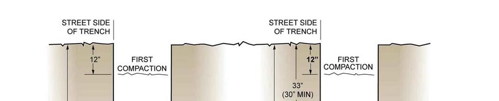
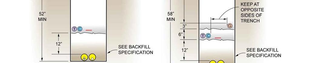
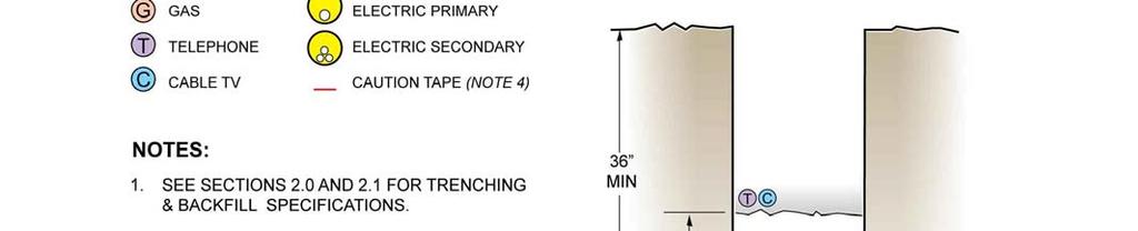
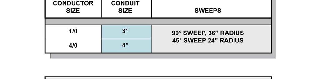
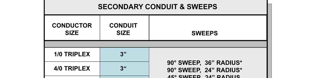
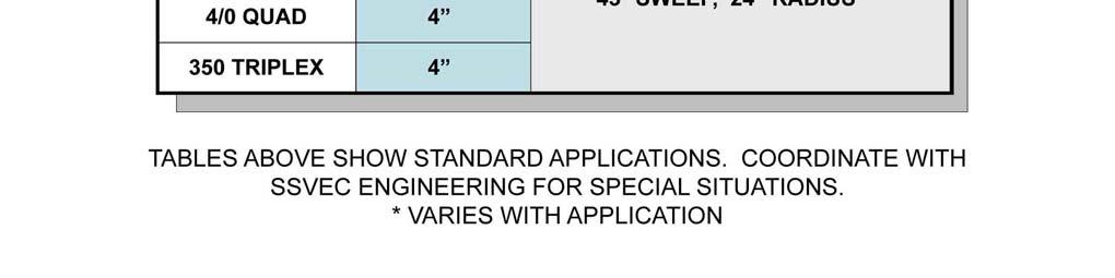
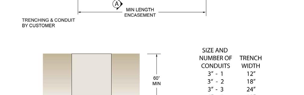
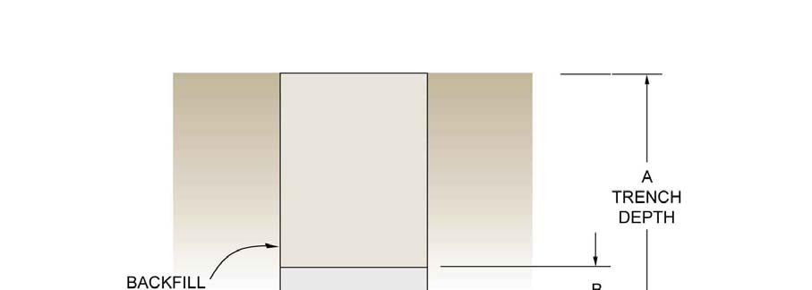
8 SECTION 200. EXCAVATION AND CIVIL WORK 2.0 Trenching and Installation Specifications In order to improve the reliability of underground electric service, the Cooperative has elected to install underground electric conductors in protective conduit, i.e. PVC or CIC (Cable-In-Conduit). Unless otherwise directed by SSVEC, the customer will be responsible for supplying and installing underground PVC conduit required for new line extensions and developments. The customer shall also furnish all necessary trenching, select backfill, warning tape, compaction, and concrete work to the specifications of the Cooperative and other local codes The following are minimum requirements for typical installations; however, field conditions may dictate other requirements. Specifications on construction drawings and/or specifications determined during the pre-construction meeting supersede the information shown here Minimum depth (measured from final grade to the bottom of the trench) for a primary system shall be 52 in a non-joint trench and 58 in a joint trench. Minimum depth from final grade for secondary system shall be 36 for non-joint and joint trenches (See Figure 200.2). Trench bottom shall be smooth, level and free of rocks and debris (NO SHARP ROCKS). Trench shall be parallel or at right angles to clearly staked right of way or property lines and be as close to right of way line as possible. Spoil shall be a minimum of 2 from trench wall. Do not mechanically excavate within 2 feet of existing facilities. Relocation of lines due to deviations from minimum cover requirements, improper location, etc., shall be done at the total expense of the developer All permits and easements for the job must be secured prior to the release of the work order. The customer is responsible for acquiring private easements and any permits required by the governing agencies. SSVEC will help facilitate the permit and easement process when deemed appropriate by SSVEC Unless otherwise indicated on the work order, all primary, secondary, and service conductors shall be installed in Schedule 40 PVC conduit with the printed specification label clearly visible on the upper side of the conduit When installing PVC conduit apply purple primer/cleaner ASTM F656 to all PVC joints prior to applying a coating of gray PVC to PVC cement ASTM D Unless otherwise indicated on the final design provided by SSVEC, sweeps/bends shall be installed in accordance with the conduit applications shown in Figure The conduit sweeps at device locations shall extend 6 inches above the floor of the basement pad. Service conduit stub-out locations shall be indentified by subdivision lot number using a permanent black ink marker. 10/28/2009 3
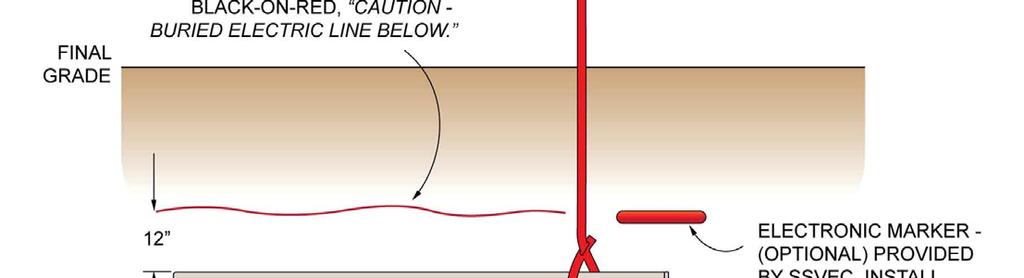
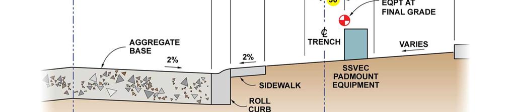
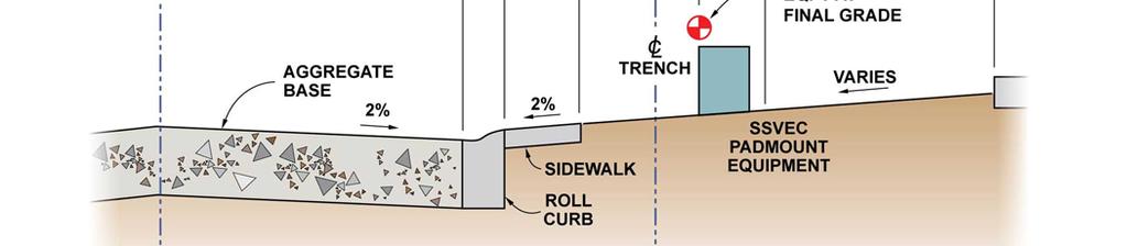
9 2.0.9 The customer shall provide and install a concrete skirt around three-phase transformer pads as shown in Figures and , and install SSVEC provided equipment box pads and junction cabinets per the final SSVEC design and work order. Conduit stubs shall be positioned in equipment as specified on the work order drawings or details. SSVEC will provide ground rods with all box pads. The customer shall install the ground rod as specified in the approved drawing details Minimum 95 percent soil compaction is required at all equipment locations (compacted area to extend 1 out from equipment). In the event of an inconsistency or conflict with other agency specifications, the more stringent specification shall apply The customer shall provide an excavation at each transformer and switch cabinet location according to the approved detail drawings. These excavations must be sufficiently deep to accommodate the conduit sweeps and box pads as illustrated in the figures attached to Section 200 of this specification or other details supplied by SSVEC. After the conduits are installed, the excavations must be backfilled and leveled to allow for the pad. The pad depth and installation must be coordinated with SSVEC construction personnel. Other excavations may be required as situations warrant Trenches should not be opened before coordination with the SSVEC Construction Foreman or the SSVEC Inspector The SSVEC Inspector shall approve trench depth changes due to obstructions encountered while digging There shall be a 12 minimum radial clearance between the electric lines and all other utilities. Crossings require a minimum of 12 vertical separation between SSVEC facilities and other utilities, including water and sewer taps. Sewer may not be placed in the same trench. Water lines are also normally in a separate trench. See Figure for the proper separation between parallel utilities. In no circumstance, will other utilities be allowed underneath SSVEC pad-mounted equipment Electric lines shall not be situated under inhabitable/enclosed structures or other utility equipment The conduit system shall be proven after backfill is completed. Unless otherwise directed by SSVEC, a mandrel, appropriately sized for the conduit, will be routed through the conduit installation leaving a mule tape of 2,500 lb. pulling capacity accessible at both ends of the conduit. All empty conduit ends shall be plugged at equipment locations. Future conduit stub-outs shall be capped and a locate marker installed per the attached drawing (See Figure ). Tape is not an acceptable substitute for caps or plugs Trench depths and pad excavation depths are based on final grade. Any change in the final grade will require replacement of line and equipment at the customer s expense All equipment pad excavations shall be level and smooth. 10/28/2009 4
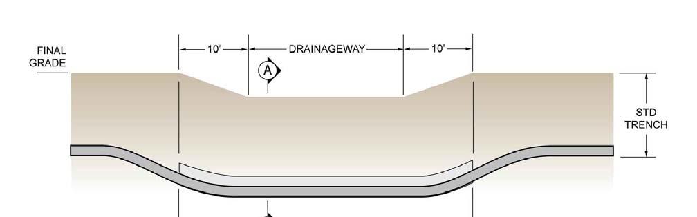
10 SSVEC approved and customer provided concrete caps shall be installed over conduit in trenches which may cross through drainage areas, washes and other areas subject to erosion and as required by the SSVEC inspector. Concrete caps shall consist of 3000 psi concrete at 28 days. The concrete cap shall cover the entire width of the trench up to a level of 6 inches above the conduit (See Figure ). Shallow trenches are also subject to concrete caps (See Figure for details) The customer shall call the SSVEC Inspector whenever excavating closer than 5 feet from existing poles and guy wires The customer shall restore to its original condition, at customer s expense, any landscaping or property which has been damaged due to customer-provided trenching, backfilling, or equipment installations SSVEC personnel must inspect and approve all trenching and backfill material prior to any item being installed in the trench. SSVEC shall be responsible for inspecting all trench, conduit and equipment installations. SSVEC will not pull underground cables until the trench and conduit have been properly inspected and completely backfilled A mandatory pre-construction meeting shall take place a minimum of five (5) working days prior to construction of primary installations. The SSVEC Inspector will initiate and help coordinate the pre-construction meeting. 2.1 Backfill Specifications % of the bedding and shading material shall pass through a 1½ standard sieve and shall not have sharp edges. This padding material shall be of sufficient quantity to provide 6 of material along side and above the pipe, and shall be approved by SSVEC personnel prior to installation of the pipe and padding material. The first 6 lift above and around the conduit shall be 1½ minus and shall be installed by the developer During the course of this installation all bedding, shading, backfill, sleeve, warning tape, material procurement, compaction, material export, site restoration, required blacktop, concrete cuts and repairs, construction staking, compaction testing, required permits, design specifications of drainage crossings, certification of grade and blue-stake notifications shall be the sole responsibility of the developer. All work shall meet the requirements of Sulphur Springs Valley Electric as well as other utility and governmental organizations under whose jurisdiction the work is to be done SSVEC reserves the right to inspect all and every part of Customer s work during or after completion of trenching, conduit installation, shading, backfilling, or compaction. If all of any part of the work has not been done according to SSVEC specifications, Customer shall take corrective action at Customer s expense. SSVEC may perform the corrective action at the Customer s expense. Neither inspection of the work by SSVEC nor lack of same shall relieve Customer of the responsibility to provide and perform the work according to SSVEC specifications. In all cases, the Customer is responsible for conduit system location, integrity and usefulness until SSVEC conductors are energized. 10/28/2009 5
11 2.2 Service Drop Installations Unless a service work order specifically calls for CIC (cable pre-installed in conduit and direct buried), the customer is required to install a 3 minimum PVC conduit preparatory to the cable installation. All line drops are coordinated on an individual basis by the line crew foreman (See Figure ) The customer is responsible for coordinating the service trench and conduit inspection with the SSVEC Construction Foreman. This inspection coordination should begin prior to opening the trench. The SSVEC Foreman will provide important information regarding the installation and inspection coordination process. The Sierra Vista Engineering Service Representative or the Construction Clerk at your local office can help connect you with the SSVEC Construction Foreman for your job All service conductors shall be installed in Schedule 40 PVC conduit with the printed specification label clearly visible on the upper side of the conduit. Unless otherwise directed by SSVEC, the conduit will be 3 diameter When installing PVC conduit apply purple primer/cleaner ASTM F656 to all PVC joints prior to applying a coating of gray PVC to PVC cement ASTM D The trench and conduit shall be inspected before the service crew visits the site. SSVEC will not pull underground cables until the trench and conduit have been properly inspected and completely backfilled SSVEC reserves the right to inspect all and every part of Customer s work during or after completion of trenching, conduit installation, shading, backfilling, or compaction. If all of any part of the work has not been done according to SSVEC specifications, Customer shall take corrective action at Customer s expense. SSVEC may perform the corrective action at the Customer s expense. Neither inspection of the work by SSVEC nor lack of same shall relieve Customer of the responsibility to provide and perform the work according to SSVEC specifications. In all cases, the Customer is responsible for conduit system location, integrity and usefulness until SSVEC conductors are energized Refer all questions to the SSVEC Construction Foreman or SSVEC Engineering. 10/28/2009 6
12 10/28/2009 7
13 10/28/2009 8

14 10/28/2009 9
15 10/28/
16 10/28/

17 10/28/
18 10/28/

19 10/28/
20 10/28/
21 10/28/


22 10/28/
23 Figure " 12" 39" 45" FRONT 76" 16" 44" 16" WIRE MESH OR REBAR BACK REMOVABLE LID 12" TOP VIEW TOP OF CONCRETE FLUSH WITH TOP OF PAD 6" FINAL GRADE 3 #4 REBAR OR 6 X 6 NO. 10 WIRE MESH FIBERGLASS PAD SUPPLIED BY SSVEC SIDE VIEW *NOTE-- REQUIREMENT: 10' CLEARANCE FROM FRONT OF TRANSFORMER PAD 2' CLEARANCE FROM BACK & SIDES OF PAD **NOTE: FOR TRANSFORMERS LARGER THAN 300 KVA, PAD DIMENSIONS ARE 96" X 96". (SEE A SPECS) SCALE DATE DR'N AP'VD TITLE KRS NORDIC.DWG NONE SULPHUR SPRINGS VALLEY ELECTRIC CO-OP, INC. CKD. Revised Pad Size For REVISIONS KVA Transformer** TRANSFORMER PAD DETAIL KVA NO. BY JMS DATE 6/93 SH 1 OF 1 10/28/
24 FIGURE " 12" 39" 45" 26" WIRE MESH OR REBAR FRONT 96" 44" BACK 26" REMOVABLE LID 12" 3 TOP VIEW TOP OF CONCRETE FLUSH WITH TOP OF PAD 6" FINAL GRADE #4 REBAR OR 6 X 6 NO. 10 WIRE MESH FIBERGLASS PAD SUPPLIED BY SSVEC SIDE VIEW *NOTE-- REQUIREMENT: 10' CLEARANCE FROM FRONT OF TRANSFORMER PAD 2' CLEARANCE FROM BACK & SIDES OF PAD **NOTE: FOR TRANSFORMERS SMALLER THAN 500 KVA, PAD DIMENSIONS ARE 76" X 96". SCALE DATE DR'N AP'VD TITLE NONE CKD. KRS NORDIC.DWG SULPHUR SPRINGS VALLEY ELECTRIC CO-OP, INC. Revised Pad Size For KVA Transformer TRANSFORMER PAD DETAIL KVA REVISIONS BY DATE NO. JMS 6/93 10/28/
25 FIGURES THROUGH These are typical specifications only and changes may occur during the course of a specific project. Conduit placement is subject to details shown on each SSVEC construction drawing provided with each job and may vary. Coordinate all civil work with SSVEC Engineering prior to installation. SSVEC reserves the right to inspect all and every part of Customer s work during or after completion of trenching, conduit installation, shading, backfilling, or compaction. If all of any part of the work has not been done according to SSVEC specifications, Customer shall take corrective action at Customer s expense. SSVEC may perform the corrective action at the Customer s expense. Neither inspection of the work by SSVEC nor lack of same shall relieve Customer of the responsibility to provide and perform the work according to SSVEC specifications. In all cases, the Customer is responsible for conduit system location, integrity and usefulness until SSVEC conductors are energized. TYPICAL CONDUIT DETAILS FIGURE FIGURE FIGURE FIGURE FIGURE PHASE TRANSFORMER PAD 1 PHASE SWITCH CABINET 3 PHASE TRANSFORMER PAD 3 PHASE SWITCH CABINET SECONDARY PEDESTAL STAKING DETAIL FIGURE STREET LIGHT FOUNDATION DETAIL FIGURE /28/
26 10/28/
27 10/28/
28 10/28/
29 10/28/
30 10/28/
31 10/28/
32 FIGURE /28/
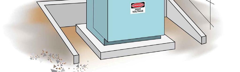
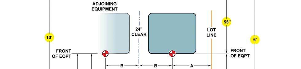
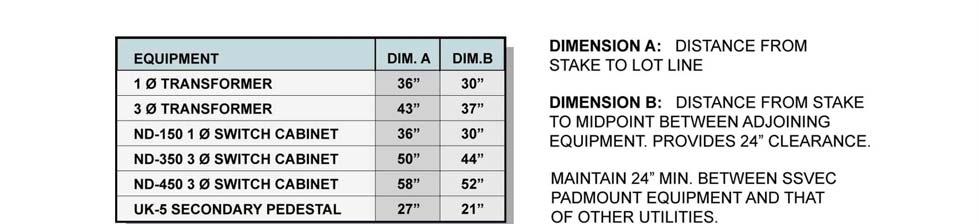
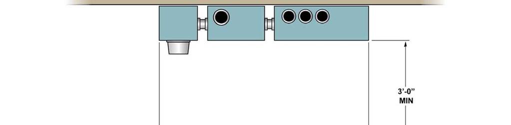
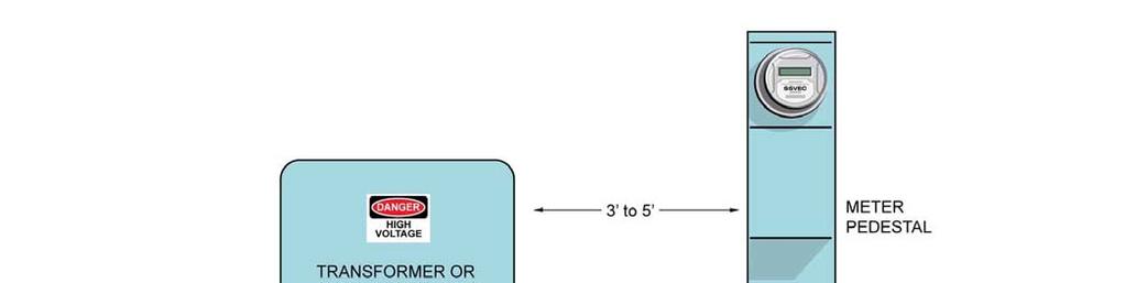
33 SECTION 300. SAFETY AND ACCESS CONSIDERATIONS 3.0 CLEARANCES Vertical clearance of service conductors above roofs and the ground shall be in compliance with NESC Table and NEC Article Clearance from Building Openings. NEC Article Service conductors... shall have a clearance of not less than 3 feet from windows, that are designed to be opened, doors, porches, fire escapes or similar locations. Exception: Conductors run above the top level of a window shall be permitted to be less than the 3 feet requirement above Clearance from Swimming Pools: Service conductor clearance over or close to swimming pools shall comply with NEC Article and other appropriate sections of the National Electrical Code. The customer or contractor may contact qualified Engineering Department personnel for advice on clearances from swimming pools A minimum of 3 feet of clearance shall be maintained from the front of any service entrance equipment A minimum of 10 feet of working clearance shall be maintained from the front of any pad-mounted equipment A minimum of 3 feet of working clearance shall be maintained from the sides of any padmount equipment No fence, barricade, or structure shall be erected or used to impede access to SSVEC poles or equipment located in any legal utility easement. Property owners served from SSVEC lines and equipment will help provide proper access to that equipment A minimum of 10 feet of working clearance from energized SSVEC overhead distribution conductors shall be maintained at all times by non-ssvec personnel in the course of construction and other duties. This safe working clearance needs to be increased accordingly for line voltages rated over 50 kv. If this clearance cannot be maintained at all times, even in windy conditions, contact qualified SSVEC personnel in construction or engineering to make other arrangements. 10/28/
34 10/28/


35 10/28/
36 10/28/


37 10/28/
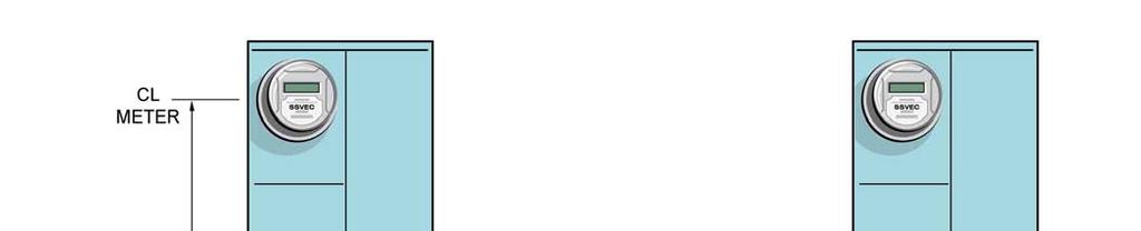
38 3.1 SERVICE ENTRANCE AND METER LOCATIONS Service entrances shall be installed in an outside location approved by SSVEC. Where practicable, service entrances should be installed so that the meter will face a dedicated alley or street for convenience of meter reading (See figure meter quadrants). All meters shall face a direction in which they can be read with binoculars from a vehicle Meters (as well as other SSVEC facilities located in dedicated easements on private property) shall not be placed behind a fence or any obstacle which will prevent SSVEC personnel from having free access to its facilities. The service entrance shall be installed in a place accessible to SSVEC and emergency personnel at all times. The service entrance shall not be locked except by an arrangement that is agreeable to both the customer and SSVEC Service entrances shall not be installed under carports or open porches or similar places that are often subject to future enclosure, nor shall they be enclosed or obstructed later. Service entrances enclosed or obstructed after service connection so that the meters cannot be read in the normal manner, shall be re-established in an outside location approved by SSVEC, or such obstruction shall be removed. Failure to comply with this rule, within a reasonable time after notification by SSVEC, shall be grounds for service disconnection. 10/28/


39 10/28/
. This combination unit shall conform to EUSERC requirements as shown on the following pages of this specification.")
 is the preferred underground service entrance installation for manufactured homes, domestic wells, and other situations where wall-mounting is impractical. 4.0.2 Similarly, underground three-phase services up to 200 amps shall use a meter base with a bottom-feed termination section.")
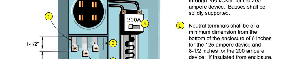
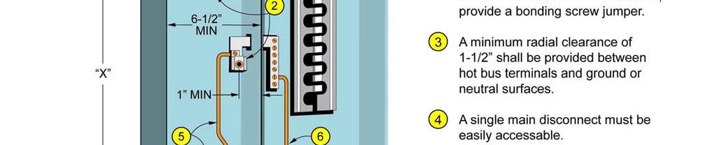
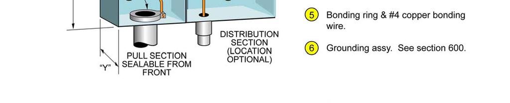
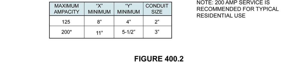
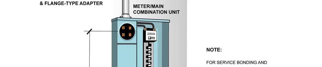
40 SECTION 400. SERVICE DISCONNECTS AND METERING 4.0 COMMERCIAL AND RESIDENTIAL SERVICES AMPS All underground residential single-phase services shall use a combination meter base with built-in single main service disconnect and pull section (See Figures through 400.8). This combination unit shall conform to EUSERC requirements as shown on the following pages of this specification. The combination meter base is also the preferred installation for overhead services. A meter pedestal (Figure ) is the preferred underground service entrance installation for manufactured homes, domestic wells, and other situations where wall-mounting is impractical Similarly, underground three-phase services up to 200 amps shall use a meter base with a bottom-feed termination section. Landing lugs shall accommodate aluminum conductors and have a range up to 250 kcmil (350 kcmil if possible). Gutter type service entrance installations are NOT approved for underground use Without prior approval by SSVEC Engineering, commercial applications will be required to supply a meter socket with a bypass (lever or test block see 4.2.3) and may utilize a separate main disconnect in those cases. 10/28/
41 4.1 SERVICE DISCONNECT AMPS All service entrances up to 200 amps shall be equipped with a single main disconnect device which shall, for this specification, determine the ampacity of the service entrance SSVEC service ampacity requirements are as follows: 60 amps is the minimum disconnect size for: (NEC D) 1. Multifamily dwelling units 2. Stock or domestic wells 3. Special approved applications 100 amps is the minimum disconnect size for: (NEC C) ** 1. One-family dwellings 2. Mobile homes 3. Small commercial ** It is strongly recommended by SSVEC that a 200 amp minimum rated service entrance be installed for any single-family dwelling or manufactured home The service disconnect over-current device shall be a single fused switch or circuit breaker. The disconnect shall be rain tight and of a type approved for service equipment, in compliance with the NEC, Article It shall disconnect all ungrounded service entrance conductors from the service load Except for motor loads, the main service disconnect nameplate ampacity is used to determine the ampacity of the service entrance.. The nameplate ampacity of a fused main switch determines the service disconnect ampacity regardless of the fuse size installed. In a circuit breaker type service disconnect, the nameplate ampacity of the main circuit breaker determines the disconnect ampacity. Where multiple disconnects are allowed for multiple-metered installations (See paragraphs and 4.7.5), the sum of the ratings of the main fused switches or circuit breakers shall not be permitted to exceed the ampacity of any main bus or the de-rated ampacity of the service conductors Services which have emergency equipment such as a water pump that may be used for fire fighting or emergency lighting, exits, etc. (see NEC ), may have additional disconnect devices connected ahead of the main disconnect device through which only the emergency equipment may be supplied. The additional device shall not affect the ampacity required for the service entrance (NEC Excep. 4), provided that the service entrance would be adequate if the emergency equipment were connected through the main disconnect The service entrance disconnect device shall be plainly and permanently labeled with the word MAIN. The emergency equipment device (if any) shall be plainly and permanently labeled with the word MAIN and the emergency function such as PUMP or EMERGENCY LIGHTS, etc. 10/28/
42 4.1.7 The disconnect device shall be located outside, in a place accessible to SSVEC and emergency personnel at all times. It shall not be locked except by arrangement that is agreeable to both the customer and SSVEC Where more than one service is permitted on a building, a permanent plaque or directory shall be installed at each service equipment location denoting all other services on that building or structure and the area served by each (NEC 230-2, E) OVERCURRENT PROTECTION: A fuse or circuit breaker shall be in series with each ungrounded conductor to provide overload protection. Interrupting Rating: The customer shall install service entrance equipment and protective devices capable of interrupting and withstanding available short-circuit current. All service disconnect devices (i.e. fused switch or circuit breaker) shall have a minimum interrupting capacity (A IC ) of 10,000 amps. Higher A IC ratings may be required at locations with higher available fault currents (NEC 110-9). Consult qualified SSVEC Engineering Department personnel for the available fault current for multiple services and for service from large transformers. When available fault current exceeds 10,000 amps (as calculated by SSVEC), the customer shall provide equipment to meet the expected maximum fault current (see NEC and 230, section VII). The customer has the option of providing service equipment with an increased A IC rating or installing equipment with current limiting fuses which would limit the maximum fault current to less than 10,000 amps For multiple metered installations, the service entrance for each occupancy shall be plainly and permanently labeled to designate the suite, room, or address of the served occupancy. 4.2 METER SOCKET AND METERING AMPS For services through 200 amps, an SSVEC approved meter base shall be furnished and installed on the supply side of the service disconnect, by the customer All meter sockets shall be U.L. listed and be so labeled. Meter/main combinations shall be labeled as a unit. Any field modifications of the unit that are non-factory approved will make void the U.L. label Residential meter sockets, up to 200 amps, may be general duty sockets rated at not less than the service disconnect ampacity. Services other than residential shall use meter sockets rated for continuous duty. The continuous duty ampacity shall not be smaller than that of the service disconnect ampacity. The recommended minimum ampacity for all residential and commercial applications is 200 amps. Commercial installations shall be equipped with bypass provisions, either test block (equivalent to a Milbank 127TB) or lever type (equivalent to a Milbank U7423-RXL) The customer shall not reroute any metered conductor through the meter socket enclosure, metering compartment, raceways, or other security sealed areas. 10/28/
43 10/28/


44 10/28/


45 10/28/

46 10/28/


47 10/28/
48 10/28/
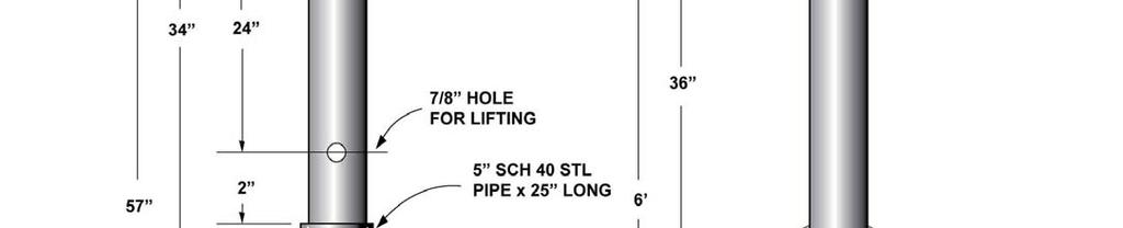
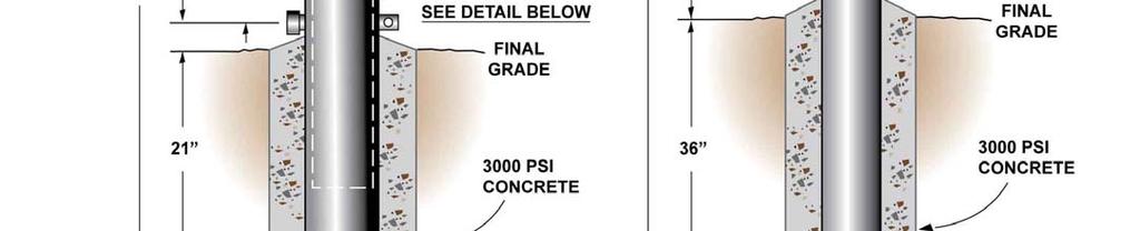
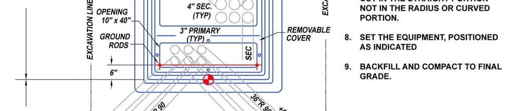
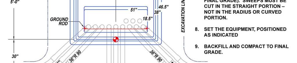
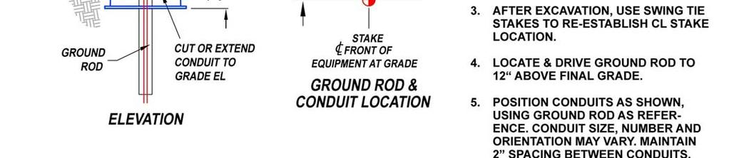
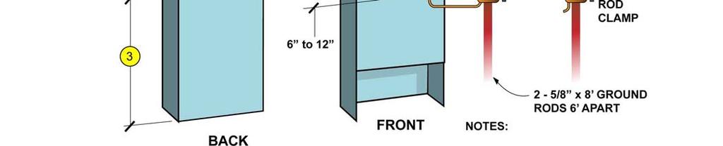
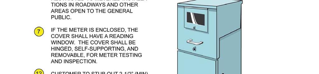
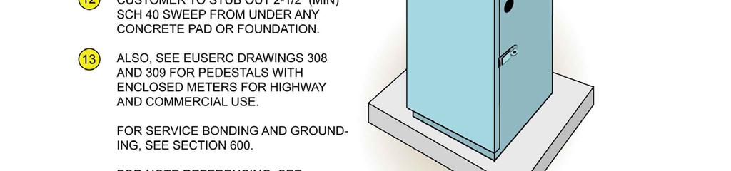
49 FIGURE NOTES FOR RESIDENTIAL AND COMMERCIAL METER PEDESTALS (FIGURES & ) 200 AMPERES, 240 VOLTS MAXIMUM 1. This type pedestal shall have a single main disconnect with a minimum rating of 100 amperes. The unit shall be of a type approved by Underwriters Laboratory (UL) and be labeled as such. 2. The post shall have a minimum cross-sectional dimension of 4 x Unless mounted on a concrete base, the unit shall be set at least 24 below existing grade, with an opening in the base to permit the service lateral conduit sweep to enter the post from the front (meter) side. The rear panel (below the service pull and termination section) shall extend 2 to 6 above grade. 4. Adequate ventilation shall be provided to inhibit condensation of moisture within the enclosure, per UL Meter shall be at least 48 above ground when exposed, or 36 when the meter is enclosed. 6. The service pull and termination section shall be accessible from either the front or rear of the post by removing a sealable full-width panel. The removable panel shall extend from the top of the unit and, when removed, allow full access to the terminating lugs. This section shall be restricted to SSVEC use only. 7. If the meter is enclosed, the cover shall have a reading window. The cover shall be hinged and self supporting, and removable for meter testing or inspection. 8. The main disconnect section shall be isolated from the service pull and termination section and to unmetered conductors. 9. The service termination lugs shall be twin, aluminum-bodied, pressure-type, No. 2 to 350 kcmil. Distance from the bottom of the panel opening to the bottom of the lug assembly shall be 18 to 48. Distance from terminating lugs to panel surfaces and any grounded surface shall be at least 1-1/2. Rigid insulating barriers are required which project at least ¼ beyond the energized parts to provide protection if the normal space is reduced. Terminating lugs may be positioned either inline or staggered. Access around pedestal shall be unobstructed when service conductors are in place. 10. An equipment grounding lug shall be provided, accessible from the grounding lug in the main disconnect section. The ground wire requires a protective sheath. 11. The meter base shall be fabricated with components tested by Underwriters Laboratory, and shall be provided with a sealing ring. The meter socket shall be mounted on a support and attached to the meter panel. The meter socket shall be factory wired with the conductors located in a separate section from the service terminating lugs to the meter socket. The conductors which extend from the meter socket to the service terminating lugs shall be connected independently of the connections for the service lateral conductors. 12. Commercial/highway pedestals with enclosed meters, mounted on a concrete base, will have a minimum 2 ½ sweep stubbed out from under the pad to accommodate CIC. 13. See EUSERC drawings 308 and 309 for specifications for pedestals with enclosed meters for highway and commercial use. 10/28/

50 10/28/


51 10/28/

52 10/28/
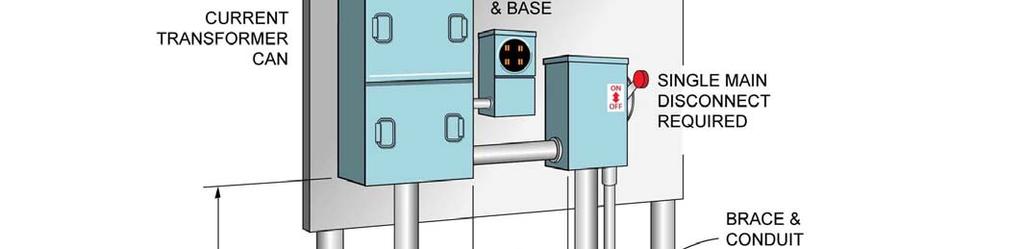
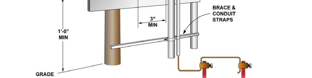
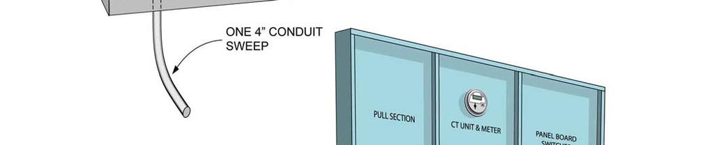
53 4.3 RESIDENTIAL AND COMMERCIAL SERVICES 201 TO 400 AMPERES MAIN SERVICE DISCONNECT All service entrances over 200 amps shall be equipped with a single main disconnect switch or circuit breaker. However, the 320 amp meter/main and multiple-meter sections with six or less meters may have more than one main disconnect as described in Sub-sections 4.4 and 4.7 of this specification. The disconnect enclosures shall be rain-tight and of a type approved for service equipment, in compliance with the NEC and the switches shall disconnect all loads from the ungrounded conductors The main service disconnect shall be plainly and permanently labeled with the word MAIN. A separate emergency equipment disconnect (if any) may be allowed and shall be plainly and permanently labeled with the word MAIN and its emergency function such as PUMP or EMERGENCY LIGHTS, etc. The disconnect device shall be located outside, in a place accessible to SSVEC personnel at all times, or shall be operable to an open position from an outside location accessible to SSVEC personnel at all times. It shall not be locked except by an arrangement agreeable to SSVEC The main service disconnect(s) shall be connected on the load side of the metering Except for motor load services, the nameplate ampacity of the main service disconnect determines the ampacity of the service entrance. If more than one main disconnect is allowed, as described in Sub-sections 4.4 and 4.7, the sum of the ampacities shall determine the ampacity of the service entrance. WHENEVER A DETERMINATION IS MADE BY SSVEC REGARDING THE LIKELY POSSIBILITY THAT MODULES, SECTIONS, OR DISCONNECTS COULD BE ADDED IN THE FUTURE, THE AMPACITY RATING OF THE BUS WILL BE USED TO QUALIFY THE TOTAL RATING OF THE SERVICE SECTION, AS WELL AS THE NEED FOR A MAIN DISCONNECT. IN NO CASE SHALL SERVICE ENTRANCE CONDUCTORS BE SIZED FOR LESS THAN THE AMPACITY RATING OF THE BUS The service entrance ampacity of a circuit breaker type of main disconnect shall be determined by the nameplate ampacity of the circuit breaker(s). The service entrance ampacity of a fused-switch type of main disconnect shall be determined by the nameplate ampacity of the switch regardless of the fuse size installed METERING FOR SERVICES AMPS CURRENT TRANSFORMER ENCLOSURE: For service entrances of 201 to 400 amperes, as determined by the nameplate ampacity of the service disconnect, a rain-tight current transformer enclosure, constructed of code gauge metal, with an approved mounting base for bar-type current transformers shall be used. The enclosure shall be furnished and installed by the customer or contractor. An approved free-standing service entrance section conforming to EUSERC requirements may be used as an alternative. 10/28/
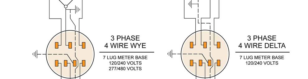
54 For single-phase three-wire services, the enclosure shall be equivalent or superior to Circle A W or Milbank Products with minimum dimensions of 24 x 36 x 11. The customer will supply the mounting base for the CT s, equivalent to a Beeline 6019-A, and bi-metal supply termination lugs with an upward range to 350 kcmil For four-wire services, delta (such as 120/240 volt) or wye (such as 120/208 or 277/480 volt), the enclosure shall be equivalent or superior to Circle A W or Milbank Products, 36 x 42 x 11 N3R CT, with a Beeline mounting base 6067-A, or equivalent, installed along with the appropriate termination lugs as noted above Any hub used to accommodate a riser shall be rain-tight in all cases The current transformer enclosure shall be equipped with a neutral termination block METER SOCKET ENCLOSURES: Meter socket enclosures, and potential transformer enclosure if needed, will be furnished and installed by SSVEC POSITION OF POWER LEG: On three-phase, four wire delta services, the power leg shall be installed in the right hand position in the meter socket and the CT enclosure INSTRUMENT TRANSFORMER METERING: Instrument transformers are used when the current or voltage of a service is too great for a self-contained meter installation. Current and potential (voltage) transformers, where required, and all associated meter circuit wiring will be furnished and installed by SSVEC at the time of service connection GROUNDED (NEUTRAL) CONDUCTOR SIZE: The neutral conductor shall be equivalent in size to the ungrounded conductors and may not be reduced in size for this specification. See warning regarding possible harmonic current in the neutral in paragraph of this specification. 10/28/


55 10/28/
56 4.4 SINGLE-PHASE 320 AMP METER/MAIN FOR RESIDENTIAL SERVICE ONLY Single-phase, continuous-rated 320 ampere meter/main enclosures which have been tested, listed and labeled by a nationally recognized testing laboratory may be used under the following conditions: Individually metered residential services may use an approved 320 amp meter socket enclosure if the disconnect ampacity does not exceed 400 amperes. This unit is typically utilized for underground installations. An auxiliary raceway is available for overhead installations (or a CT can may be utilized see Sub-section 4.5) The 320 amp meter socket is not approved for use on commercial installations. (Commercial installations require the use of CT cans see Sub-section 4.5) The service entrance will be capable of carrying the total current of the service supplied to the customer and of being directly connected to the line voltage of the service. The socket will accommodate a standard self-contained meter. SSVEC will supply the meter. Bolt-in type 400 ampere meter sockets are not acceptable This specification allows for two 200 amp disconnects to be used, which is standard for the 320 amp meter/main combination Underground services shall use a 3 conduit for the service entrance riser. 10/28/


57 10/28/
58 10/28/
59 4.5 COMMERCIAL & RESIDENTIAL SERVICES AMPERES MAIN DISCONNECT (SSVEC REQUIRES A SINGLE MAIN DISCONNECT--SEE 4.3.1) CURRENT TRANSFORMER ENCLOSURE: For service entrances of 401 to 800 amperes, as determined by the nameplate ampacity of the service disconnect, a weather tight current transformer enclosure, with an approved mounting base for bar-type current transformers shall be used. The enclosure shall be furnished and installed by the customer or contractor. An approved free-standing service entrance section conforming to EUSERC requirements may be used as an alternative. (For specifications regarding service entrance sections, see section 4.7) For single-phase three-wire services, the enclosure shall be equivalent or superior to Circle A W or Milbank Products with minimum dimensions of 24 x 48 x 11 N3R CT (UL Standard 414) For four-wire services, delta (such as 120/240 volt) or wye (such as 120/208 or 277/480 volt), the enclosure shall be equivalent or superior to Circle A W or Milbank Products, 36 x 48 x 11 N3R CT (UL Standard 414) Please note that a 3 or 4 hub is optional for the 800 ampere cabinet. A 3 hub is factory type for the 400 ampere enclosures. Where a larger hub is needed, a knockout type weather-tight hub shall be used The current transformer enclosure shall be equipped with a neutral termination block METER SOCKET ENCLOSURES: Meter socket enclosures, and potential transformer enclosure if needed, will be furnished and installed by SSVEC POSITION OF POWER LEG: On three-phase, four wire delta services, the power leg shall be installed in the right hand position of the meter socket and the CT enclosure INSTRUMENT TRANSFORMER METERING: Instrument transformers are used when the current or voltage of a service is too great for a self-contained meter installation. Current and potential (voltage) transformers, where required, and all associated meter circuit wiring will be furnished and installed by SSVEC at the time of service connection GROUNDED (NEUTRAL) CONDUCTOR SIZE: The neutral conductor shall be equivalent in size to the ungrounded conductors and shall not be reduced in size for this specification. See warning regarding possible harmonic current in the neutral in paragraph of this specification. 10/28/


60 10/28/

61 10/28/


62 10/28/
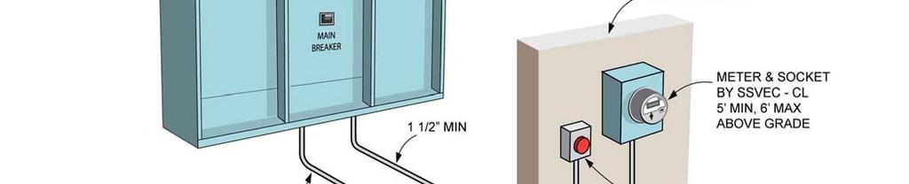
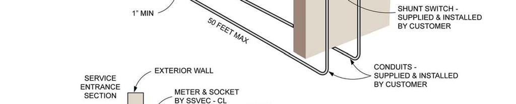
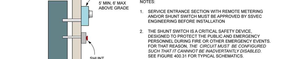
63 4.6 COMMERCIAL & RESIDENTIAL amperes / volts MAIN DISCONNECT (SSVEC REQUIRES A SINGLE MAIN DISCONNECT--SEE 4.3.1) DETERMINATION OF SERVICE ENTRANCE AMPACITY: The service entrance ampacity shall not be larger than 3000 amperes for this specification and, except for some multiple-metered installations and motor loads, the nameplate ampacity of the main service disconnect determines the ampacity of the service entrance which shall not exceed the ampacity of the bus. In all cases, service conductors shall be sized to accommodate the ampacity of the bus. Customers requiring more than 3000 amperes shall consult the SSVEC Engineering Department for special design requirements The service entrance ampacity of a circuit breaker type of main disconnect shall be determined by the nameplate ampacity of the circuit breaker The service entrance ampacity of a fused or solid state type of main disconnect shall be determined by the ampacity rating of the bus SERVICE ENTRANCE SECTION: A free-standing service entrance section, conforming to EUSERC specifications, mounted on a concrete pad or floor shall be furnished and installed by the customer or contractor on all services from 801 to 3000 amperes. A free-standing service entrance section, conforming to EUSERC specifications, is acceptable but not required for services rated less than 801 amperes. All free-standing service entrance equipment is subject to being rejected unless it has the appropriate manufacturer s drawings submitted to SSVEC Engineering for approval prior to ordering and installing said equipment SERVICE ENTRANCE SECTION LOCATION: Service entrance sections shall be permitted to be located inside buildings only under the following conditions: SSVEC personnel shall be permitted to have access to the service entrance at all reasonable times The main disconnect device shall be operable by a shunt trip device (powered directly from the main bus) located outside and accessible to SSVEC personnel at all times The customer or contractor shall run separate conduits for the metering circuit (1 RIGID minimum) and for remote operation of the main disconnect (1/2 RIGID minimum) a distance not to exceed 50 (fifty) feet to an approved outside location accessible to SSVEC personnel at all times (See Figure ). This requirement may be waived when the customer has made prior arrangements with SSVEC to have the metering equipment installed in a dedicated transformer If any of the above conditions is not met, the service entrance section shall be located outside in a place accessible to SSVEC employees at all times, and shall not be locked except by an arrangement agreeable to both the customer and SSVEC. 10/28/
64 If located outside, the service entrance section shall be raintight (NEMA 3R) METER SOCKET ENCLOSURES: For outside service entrances, meter sockets and panels, per EUSERC drawings, shall be furnished and installed by the customer or contractor in the manufactured service entrance section. When the service entrance equipment is located inside with metering conduit run outside, meter sockets and enclosures will be furnished and installed by SSVEC CURRENT AND POTENTIAL TRANSFORMERS: Current transformers, meter test switches and potential transformers, if required, will be furnished and installed at the time of service connection by SSVEC personnel in the space provided by the customer DRAWING SUBMITTAL: To avoid costly changes, the customer or contractor shall have the manufacturer submit service entrance drawings to SSVEC for review and approval by the Line Extension Services Manager before the equipment is manufactured. Faxed submittals are not acceptable for approval purposes GROUNDED (NEUTRAL) CONDUCTOR SIZE: The neutral conductor shall be equivalent in size to the ungrounded conductors and shall not be reduced in size for this specification. See warning regarding possible harmonic current in the neutral in paragraph of this specification. 10/28/
65 10/28/
66 10/28/


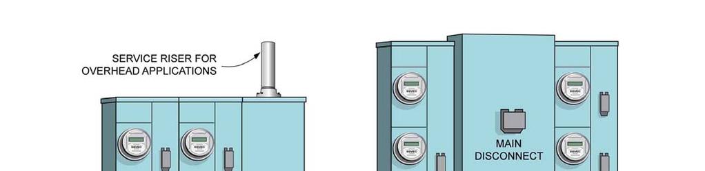
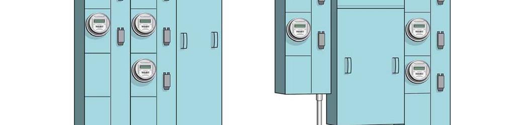
67 4.7 MULTIPLE METERED INSTALLATIONS For this specification, there are three types of service configurations generally accepted by SSVEC. Prior to the installation of any multiple metered service entrance, the customer shall submit a configuration drawing to SSVEC for approval Type I installations shall be used on multiple occupancy buildings or mobile home parks where the customer chooses to group not more than 6 meters at a common location (NEC ) and the total service ampacity does not exceed 800 amps***. TYPE I Type II and Type III installations shall be used on multiple occupancy buildings when more than 6 meters are grouped at a common location and/or the total service ampacity exceeds 800 amps***. TYPE II TYPE III Note: Gutter type installations are not approved for use except in specific pre-approved applications. ONLY QUALIFIED ENGINEERING PERSONNEL ARE AUTHORIZED TO ALLOW PRIOR APPROVALS FOR THE USE OF A GUTTER IN CERTAIN MULTIPLE- METER SITUATIONS. 10/28/
68 4.7.4 The service entrance to each occupancy shall be equipped with a single disconnect device. The nameplate ampacity of this device shall determine the service ampacity for each occupancy. 200 amps is the maximum disconnect size allowed for each individual occupancy for Types I and II (wall-mounted) installations. Any combination of selfcontained or instrument rated metering may be allowed for Type III (free-standing SES). For configuration types II and III, in addition to the disconnect device for each occupancy, a central main disconnect ( cold sequence ) device will also be required. A cold sequence disconnect device is optional for Type I installations Where multiple disconnects are allowed for multiple-metered installations (See paragraph 4.7.2), the sum of the ratings of the main fused switches or circuit breakers shall not be permitted to exceed the ampacity of any main bus or the derated ampacity of the service conductors. AT THE SOLE DISCRETION OF SSVEC, THE AMPACITY RATING OF THE BUS MAY BE USED TO QUALIFY THE TOTAL RATING OF THE SERVICE SECTION, AS WELL AS THE NEED FOR A MAIN DISCONNECT, WHENEVER A DETERMINATION IS MADE BY SSVEC REGARDING THE POSSIBILITY OF MODULES, SECTIONS, OR DISCONNECTS BEING ADDED IN THE FUTURE For multiple metered installations, the service entrance for each occupancy shall be plainly and permanently labeled to designate the suite, room, or address of the served occupancy For residential services, to determine the total service ampacity, multiply the sum of the ampacities of the single disconnect devices by the demand factors found in the NEC, Table Example Demand Factors: 2 units None 3-5 units 45% 8 10 units 43% Example Calculation for 14 units with a demand factor of 40%: Determine the total service ampacity for a service consisting of fourteen services, nine 60 amp and five 100 amp disconnects. 9 x 60 amps = 540 amps 5 x 100 amps = 500 amps 1040 amps total 1040 amps x 40%= 416 amps In this example, the central main disconnect and service entrance conductors must be sized to carry at least 416 amps For commercial services, the total service ampacity is based on the calculated or computed load as per the NEC /28/

69 10/28/


70 10/28/
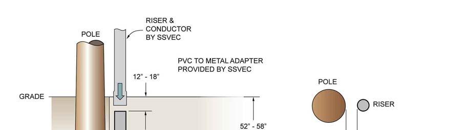
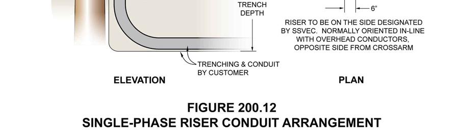
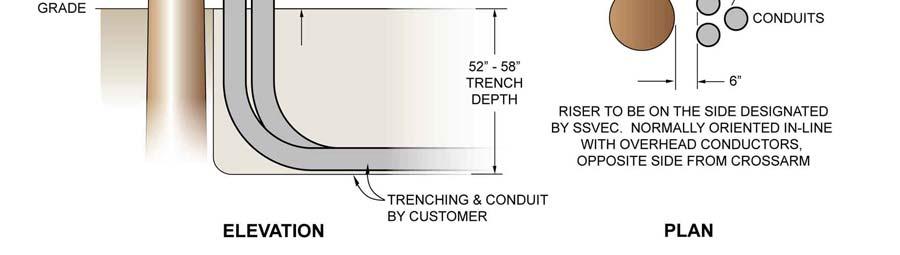
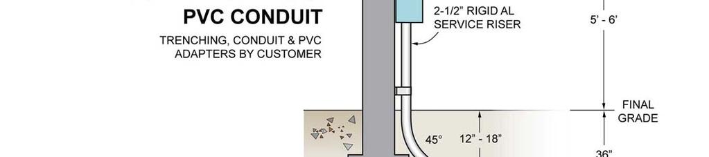
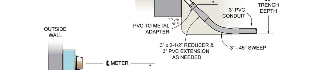
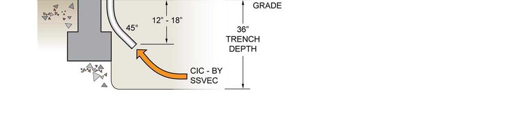
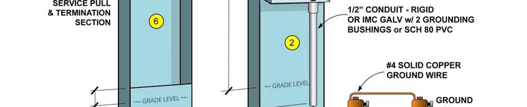
71 SECTION 500. SERVICE CONDUIT AND CONDUCTORS 5.0 SERVICE CONDUIT (OVERHEAD SERVICES) The customer shall furnish the service entrance riser conduit. This conduit shall be galvanized rigid metallic conduit or intermediate metal conduit (IMC) and shall be factory stamped as "RIGID" or "IMC". NEC (conductor protection). Galvanized water pipe or thinner walled electric metallic tubing (EMT) are not acceptable. The service entrance conductors for overhead services shall be installed in conduit no smaller than is permitted by the NEC for the size and number of conductors used Where the service entrance conduit extends through the roof and supports the service drop attachment, conduit no smaller than 2" (trade size) shall be used for single-phase services and 3" (trade size) is the minimum acceptable conduit size for three-phase services The service entrance conduit shall be capped by an approved service entrance weather head and the service entrance conductor shall be left extending from it a minimum of 3 feet. A rain-tight hub shall be used to connect the service entrance conduit to the meter base, gutter, or other approved enclosure To determine proper conduit sizes, refer to the conduit size table of the National Electric Code Appendix C. 5.1 SERVICE LATERAL RISER CONDUIT (UNDERGROUND SERVICES) Service lateral conduit from the transformer or secondary pedestal to the service lateral riser conduit will be installed by the customer unless SSVEC elects to utilize CIC (Cable in Conduit) The customer shall furnish the service lateral riser conduit. This conduit shall be galvanized rigid metallic conduit or intermediate metal conduit (IMC) and shall be factory stamped as RIGID or IMC (see NEC ). Galvanized water pipe or thinner walled electric metallic tubing (EMT) are not acceptable for use as service lateral riser conduit Rigid conduit no smaller than 2 ½ shall be used for all single-phase services up to 400 amps and three-phase services up to 200 amps. A minimum diameter of 3 shall be used for single-phase services from amperes and for three-phase services from amps. A 45º kick (bend) shall be required to clear the footer Two parallel conduits, 4 minimum diameter, are suitable for amp services. Conduits shall be stubbed out beyond any concrete pads or foundations for easy access by the utility. Consideration should be given, in sizing encased conduits, future requirements and possible upgrades. 10/28/
72 5.1.5 The rigid conduit shall be run to a point not less than 12 inches and not more than 18 inches below finished grade Both ends of the rigid conduit shall be reamed and threaded, with an insulated bushing installed on the top end. A PVC adapter will be installed on the bottom end by SSVEC Rigid metallic conduits and fittings installed underground or in concrete shall be protected against corrosion by half-wrapping with an approved plastic tape or by a coating of an approved corrosion-resistant material. NEC a, b & c. 10/28/


73 10/28/
74 5.2 SERVICE ENTRANCE CONDUCTORS GENERAL The customer or contractor shall not reroute any metered conductor through the meter socket enclosure, metering compartment, raceways or other security sealed areas Because of high ambient temperatures likely to be encountered in outdoor service entrances, no conductor with insulation rated lower than 75 degrees C. shall be used. All service entrance conductors shall be stranded. Manufactured service entrance equipment shall be listed by a nationally recognized testing laboratory and the factory installed conductors shall be accepted at nameplate rating of the unit Service entrance conductor ampacity shall be determined from Table of the latest edition of the NEC Service entrance conductors for overhead services shall be furnished and installed by the customer or contractor. The conductors will exit the upper end of a rigid steel conduit through an approved weatherhead. Overhead services using bus duct shall have entrance heads conforming to EUSERC requirements OVERHEAD SERVICE ENTRANCE CONDUCTORS No more than four conductors per phase shall be used. All service entrance conductors shall be stranded All service entrance conductors in the riser (and also any conductors that run from the load side of CT section to the disconnect device) shall be furnished and installed by the customer. The service entrance conductors shall have ampacities sufficient to carry the load as determined by the service disconnect ampacity. Conductor ampacities can be limited by correction factors determined by conditions of excessive heat (see NEC Tables ,B,2,a and ) All ungrounded conductors of three-phase services shall be clearly identified at both ends by tape or other effective means. Phase B shall be the power leg (highest voltage to ground) on three-phase four-wire delta services and shall be durably and permanently marked by an outer finish that is orange in color or by other effective means (NEC ) On three-phase four wire delta services, the power leg shall be connected to the right hand meter base and CT enclosure terminals. The power leg conductor, on three phase four wire delta services, shall not be reduced in size from that of the other ungrounded conductors. 10/28/
75 For all services, the grounded conductor (neutral) shall not be reduced in ampacity from that of the ungrounded conductors. NOTE: Electric discharge lighting, data processing equipment, and variable speed motors may create harmonic currents in the neutral that may exceed the load current in the ungrounded conductors. Although not mandated by SSVEC, it may be appropriate to require an oversized feeder neutral conductor depending on the total harmonic distortion contributed by the equipment to be supplied The grounded conductor shall enter the service entrance or service lateral conduit, continuing straight through the meter base to terminate at the neutral lug in the main disconnect switch. The grounded conductor must be bonded at the meter base but may not be spliced at the meter base neutral lug The grounded conductor (neutral) if copper may be bare. If insulated conductor is used, the insulation shall be white or natural gray or shall be permanently identified at both ends with white or natural gray tape. (NEC 230-4, A and NEC 200-6) 10/28/
76 FIGURE RESIDENTIAL WIRE SIZE TABLE AMPERAGE COPPER WIRE SIZE ALUMINUM WIRE SIZE 100 #3 MINIMUM #2 MINIMUM 125 #2 #1/0 150 #1 #2/0 200 #3/0 #4/0 400 PARALLEL #3/0 PARALLEL 300 kcmil Notes: #1. Information for wire size tables taken from National Electrical Code Article and Table All wire sizes in the table above are based on 90 C. Conductors rated 75 C. may also be used but must be adjusted per NEC Table The wire sizes in the table above are only suggestions based on minimum requirements and are for residential services only. See Note 2 below for commercial applications. #2. Commercial services usually have a higher load factor than residential services. SSVEC uses the ampacity correction factors for an ambient temperature of 36 to 40 C. (97 to 104 F.) to determine the allowable ampacity for conductors used for commercial services. Conductors with 75 C. insulation are derated to 88% and those with 90 C. insulation are derated to 91%. #3. Only insulation types RHH, THHN, XHHW 90 C. and RH, RHW, RUH, THW, THWN, XHHW, USE 75 C. are acceptable for service entrances on SSVEC's system. #4. No cable with an extra covering such as romex shall be used for service entrance conductors. #5. When 90 C. insulation is used all lugs shall also be rated 90 C. 10/28/
77 5.3 SERVICE LATERAL CONDUCTORS (UNDERGROUND SERVICES) SSVEC will furnish and install all service lateral conductors up to and including 800 amps. Conductors for services larger than 800 amperes and where conductors are under or inside a building shall be furnished and installed by the customer or contractor. SSVEC will furnish and install connectors at the transformer up through 800 amps No conductor larger than 750 kcmil, no more than six copper conductors per phase or seven aluminum conductors per phase, and no conduit larger than six inch trade size shall be used without special review and prior approval by qualified SSVEC personnel. For services requiring larger conductor or conduit, approved bus duct shall be used SSVEC will connect the service lateral conductors up through 800 amps to the landing lugs at the customer s meter base or termination section and at the transformer or secondary pedestal in all cases SSVEC will not furnish, install, or assume responsibility for conductors under or inside of any building. 10/28/
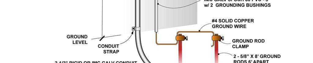
78 SECTION 600. SERVICE BONDING AND GROUNDING 6.0 SERVICE BONDING The neutral conductor and all service equipment enclosures shall be effectively bonded together (see NEC ) A wire, bus, screw or similar suitable conductor may be used for bonding. If a wire is used, it shall be no smaller than 6 AWG copper. For other acceptable means of bonding, see NEC GROUNDING ELECTRODE CONDUCTOR An unspliced copper grounding electrode conductor shall be connected, on the supply side in the service disconnect enclosure, to the grounded (neutral) conductor and run to an approved grounding electrode When the Grounding Electrode Conductor is installed in an outside location such as on a service pole or on the outside of a building the conductor shall be installed in a protective conduit The protective conduit shall be galvanized rigid metallic conduit, intermediate metal conduit (IMC) or sunlight resistant Schedule 80 PVC conduit, and shall be factory stamped as "RIGID" or "IMC" or Schedule 80. The protective conduit shall attach to the service disconnect or other approved enclosure in a weather-tight manner and run to a point not less than 6" or more than 12" below finished grade. Rigid metallic conduits and fittings installed underground or in concrete shall be protected against corrosion by half wrapping with an approved plastic tape or by a coating of an approved corrosion resistant material. (NEC 300-6, A & B). When a metallic protective conduit is installed, the grounding electrode conductor shall be bonded to the metallic protective conduit at its entrance and exit points. (NEC , E) When approved by SSVEC and an authorized municipal or county building official, the grounding electrode conductor may be routed up through the inside of a wall. A protective conduit will not be required for this type of installation Local codes require the grounding electrode conductor to be no smaller than #4 AWG, even to a ground rod, and no smaller than allowed by the NEC for the size of service connected (NEC Table ). 10/28/
79 6.2 GROUNDING ELECTRODE All service entrances shall be connected to an approved grounding electrode. SSVEC will accept grounding electrodes as follows: When a metal underground water pipe (a metal water pipe in direct contact with the earth for 10 feet or more) or a metal well casing is located within 25 feet of the service entrances, the water pipe or casing shall be used as the grounding electrode. This type of grounding electrode shall be supplemented by one of the following grounding electrodes. (NEC Article ) A minimum of two 5/8 inch by 8 foot copper or copperweld ground rods installed 6 feet apart may be used as the grounding electrode and installed such that at least 8 feet of length is in contact with the soil. All reasonable means will be used to insure the upper end of the ground rod is driven vertically to a point not less than 6 inches below finished grade and after inspection by SSVEC shall be covered. If vertical driving is not possible because of a rock bottom, the rod may be driven at an oblique angle not to exceed 45 degrees from vertical (NEC Article , G). Any other ground rod applications or configurations are not approved unless through special review and consideration by qualified SSVEC personnel If an outside metal underground water pipe is located more than 25 feet from the service entrance, the consumer may bond this water pipe to the grounding electrode to obtain a better grounded system Other grounding electrodes (e.g. UFER) as specified in the NEC Article , (c) will be accepted only if previous arrangements have been made with SSVEC personnel to permit inspection before cover up. The Cooperative will accept as a "previous arrangement" the inspection of an authorized municipal or county building official qualifying that a UFER ground was properly installed Any grounding electrode which does not have a resistance to ground of 25 ohms or less, as measured by SSVEC, shall be augmented by one or more additional electrodes, until the combined electrodes have a resistance to ground of 25 ohms or less as measured by SSVEC (NEC ). Note: City, county, and state specifications require a minimum of two ground rods, spaced 6 feet apart, for all services where an adequate UFER ground has not been installed If there is reason to believe that a driven ground rod may not be of the required eight foot length, as decided by SSVEC, an additional electrode may be required The grounding electrode conductor clamp, including the bolt or screw, shall be solid brass or bronze or stainless steel, to prevent failure by corrosion. (NEC ) 10/28/
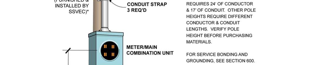
80 SECTION 700. MOUNTING AND FASTENING 7.1 The service entrance equipment shall be securely fastened to a wall or other permanent structure in a safe and workmanlike manner. The structure shall be constructed to last the thirty-five year life of the service. Acceptability of materials and workmanship shall be determined by SSVEC. 7.2 Service entrances shall be installed so that the meter is level and not more than six feet and no less than five feet above finished grade to the center of the meter socket. Mobile home type meter pedestals shall be no more than five feet and no less than three feet above finished grade to the center of the meter socket. 7.3 Nipples connected to the meter base shall not be shorter than 3 inches nor longer than 6 inches. Holes made in meter bases, disconnect enclosures, etc., shall be made in a neat and workmanlike manner and unused holes shall be covered with suitable rain-tight metallic covers. Damage to the finish, paint galvanizing, etc., of all exposed ferrous metal parts shall be touched up with paint or a suitable coating to restore corrosion resistance. Poorly painted, bare non-galvanized or rusty steel enclosures shall be painted to provide corrosion resistance. 7.4 All conduit straps used to fasten service entrance conduit to a wall or other structure shall be the two hole type rigid conduit strap or clamp type conduit hanger, and of proper size for the conduit. 7.5 No more than two conduits shall be mounted vertically on any SSVEC service pole. 10/28/
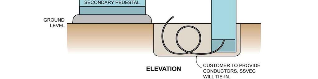
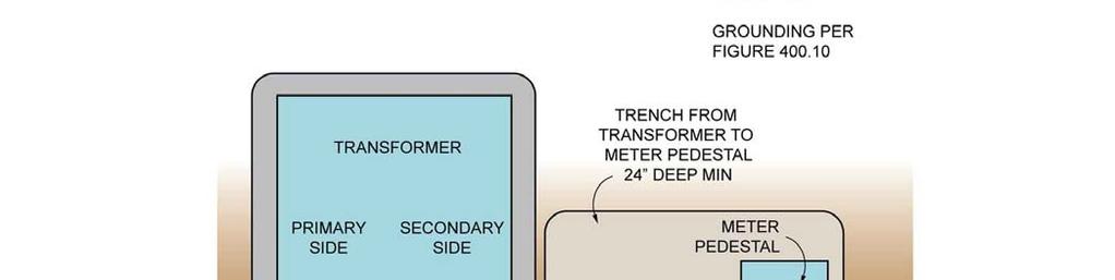
81 SECTION 800. TEMPORARY SERVICES 8.1 TEMPORARY SERVICE ENTRANCES: Temporary service entrances shall meet the same requirements as permanent service entrances. 8.2 TEMPORARY SERVICE ENTRANCE CHARGES: The customer or contractor shall pay in advance the installation and removal cost (up and down charge) for each specific temporary service connection. This cost will be determined by the SSVEC Engineering Service Representative or Field Technicians at the Sierra Vista, Benson, or Willcox offices. 8.3 TEMPORARY OVERHEAD SERVICES: Temporary overhead service entrances may be mounted on an existing SSVEC power pole supplying the appropriate voltage. Customer installed poles are not allowed. Customers are encouraged to check with SSVEC Engineering prior to the installation in order to verify the adequacy of power poles for temporary use. 8.4 TEMPORARY UNDERGROUND SERVICES: The preferred temporary underground service equipment is an approved mobile home type meter pedestal (See Figure 800.1) of this specification. With advanced approval by SSVEC Engineering, other configurations may apply for jobsite installations. 8.5 For underground temporary services, SSVEC will utilize the customer s conductor, if existing and properly rated for the ampacity of the service disconnect, and tie it into the transformer or secondary pedestal. Otherwise, for an additional charge, SSVEC may furnish and install the conductors from the transformer or secondary power pedestal and make connection to the terminals in the customer or contractor furnished meter pedestal. The meter pedestal should be installed within five (5) feet of the transformer or power pedestal. The trench shall be furnished by the customer or contractor and shall not be less than twenty-four (24) inches deep. 10/28/


82 10/28/
83 SECTION 900 FAULT CURRENTS AVAILABLE SHORT CIRCUIT CURRENT AT THE TRANSFORMER The National Electrical Code, State, County and Municipal Codes and/or Regulations require that service entrance equipment shall be suitable for the short-circuit current available at its supply terminals. It is the responsibility of the Customer to install service entrance equipment and protective devices (fuses or circuit breakers) capable of interrupting and withstanding the available fault current. Table illustrates standard interrupting and bracing capabilities commonly manufactured in service equipment for residential and commercial applications up through 400 amps. These A IC ratings represent minimum interruption and bracing capabilities to be provided by the customer in the service equipment. The ratings are typically within the short-circuit limits of any standard SSVEC transformer utilized for service applications. In some cases where a transformer feeds or will feed more than one section, the utility contribution at the delivery point may exceed the stated value. Customers should consult qualified SSVEC Engineering Department personnel for the available fault current for multiple services and for services over 400 amps, specific to the design of the actual SSVEC distribution system which will serve them. Actual fault current values are based on an infinite bus calculation at the transformer. The Customer s load shall not exceed the power quality impact described in IEEE-519, Recommended Practices and Requirements for Harmonic Control in Electric Power Systems. TABLE MINIMUM SERVICE EQUIPMENT SHORT CIRCUIT CAPABILITIES SERVICE EQUIPMENT SERVICE EQUIPMENT PHASE TYPICAL SSVEC A IC RATING AMPERAGE VOLTAGE TRANSFORMER SIZE kva 25 kva 10, RESIDENTIAL & 3 15 kva 25 kva 22,000 & COMMERCIAL RESIDENTIAL & 3 25 kva 37.5 kva 22,000 & COMMERCIAL & 3 10 kva 50 kva 14,000 10/28/
84 SECTION MOTOR START REQUIREMENTS GENERAL MOTOR LOAD (0-500 HORSEPOWER / volts) (compare to Exhibit H as filed with the ACC effective 9/1/2009) GENERAL REQUIREMENTS Note: Before any motor installation larger than 50 HP is planned qualified personnel in the Engineering Department should be consulted To assure all customers of uniform, well regulated service, it is necessary that the following motor requirements and general information be adhered to for installations on SSVEC lines Abnormal loads are those requiring non-standard voltages, or three phase motors 200 HP or larger, or single phase motors larger than 10 HP, or single phase to three phase converters, or intermittent loads (large welders, electric furnaces, elevators), or other requiring non-standard service characteristics. SSVEC may at its option extend service to an abnormal load Motors and equipment can have special load requirements that cause excessive voltage/current and harmonic changes to SSVEC s system. When SSVEC must install special equipment to protect against SSVEC system problems caused by the Customer s equipment, the Customer shall pay the excess costs SSVEC reserves the right to inspect and test all motors and other devices and equipment which are owned by the Customer and which are, or shall be, connected to SSVEC s lines PROTECTION OF MOTORS AND OTHER EQUIPMENT Under/Over voltage, overload, phase failure (single phasing), phase reversal, power interruptions and short circuit protection is strongly recommended for each motor installation It is the customer s responsibility to provide adequate protective equipment to protect the customer s equipment from high or love voltage, Phase loss or reversal or any unusual condition SSVEC will not be responsible in any way for damage to Customer s equipment due to failure of the Customer to provide adequate protective devices, or due to any failure of such devices VOLTAGE FLUCTUATION LIMITS High starting (locked-rotor) currents create voltage dip which may cause objectionable light flicker and problems operating other equipment. The voltage dip shall not exceed 4% and must be maintained within tolerable limits. 10/28/
85 Voltage dip caused by the Customer s equipment in excess of these limits may require SSVEC to disconnect the Customer s service until corrective action is taken by the customer to the satisfaction of SSVEC In addition to complying with starting requirements, running motors with fluctuating loads shall not cause excessive voltage fluctuations MOTOR STARTING Single-Phase Motors Below 10 HP: Do not require reduced voltage/current starters HP or Larger: Considered an abnormal load and may be extended service at SSVEC s option. SSVEC engineering will determine on a case by case basis if motor may be extended service. Will require reduced voltage/current starting Written Pole Motors up to 60 HP: Reduced voltage/current starting limits current at no more than 50% of locked rotor values. SSVEC engineering will also need to determine if motor may be extended service Will be limited to 60 HP maximum on SSEVC service Three-Phase Motors Up to 60 HP: Do not require reduced voltage/current starters HP: Reduced Starting Requirements (Use one of the following starting methods) Primary Resistor or Reactor: For resistor starting, resistor shall be sized to limit starting currents to no more than 60% of locked rotor current. Autotransformer: Required 50% tap Wye-Delta Solid-State (soft start): Required 50% or less of starting current setting. Part Winding motor may be considered if starting current is limited to 60% (typical range is 60%-75%) of locked-rotor. SSVEC engineering will determine if service can be extended on a case by case basis HP It is preferred for these motors to utilize a soft start set at 50% or less of normal starting current, plus a SSVEC engineering study to determine the expected voltage dip to determine soft start settings. Other reduced starting methods may be considered for these motors once the engineering study has 10/28/
86 been completed. Motors 200 hp or larger are considered abnormal loads and may be extended service at SSVEC s option HP or Larger Customer will need to provide engineered design. Design should include at a minimum a one-line diagram, load information, and motor starting information Engineered design must be signed by an Electrical Engineer with a State of Arizona P.E. license Design must be approved by SSVEC engineering before Customer can proceed with project If after installation, voltage dip limits are exceeded, the service will be disconnected until corrective action is taken by Customer to the satisfaction of SSVEC VARIABLE FREQUENCY DRIVES 1Ø to 3Ø CONVERTER REQUIREMENTS Variable Frequency Drives The Customer s load shall not exceed the power quality impact described in IEEE-519, Recommended Practices and Requirements for Harmonic Control in Electric Power Systems The customer shall be responsible to make sure the installation complies with the guidelines set forth in IEEE-519 as measured at the point of common coupling (PCC). At the very least, if the Customer is unable to verify performance, the Customer shall install one of the following at Customer s expense: 6-Pulse Drive w/5% Line Reactor 6-Pulse Drive w/3% DC Link Choke 6-Pulse Drive w/drive-applied harmonic filter 12-Pulse Drive w/delta-delta drive isolation transformer Single-Phase to Three-Phase Converters Considered an abnormal load and may be extended service at SSVEC s option The Customer s load shall not exceed the power quality impact described in IEEE-519, Recommended Practices and Requirements for Harmonic Control in Electric Power Systems Customer will need to provide an engineered design. Design should include at a minimum a one-line diagram, load information, and motor starting information. 10/28/
87 Design must be signed by an Electrical Engineer with a P.E. license Design must be approved by SSVEC engineering before Customer can proceed with project If after installation, voltage dip limits are exceeded, the service will be disconnected until corrective action is taken by the customer AIR-CONDITIONING UNITS (Compressor Motors) The high starting (locked-rotor) currents of the compressor motor may cause objectionable light flicker seen by the customer. In the case of Customer complaints, a three-wire Hard Start or Kickstart kit will be required by SSVEC. The Hard Start or Kickstart kit s installation and costs are the Customer s responsibility. Customers may check with a local HVAC dealer for information on Hard Start or Kickstart kits If light flicker still persists after the Hard Start or Kickstart installations, SSVEC will take corrective action if the voltage at the Customer s meter extends into Range B voltage, set forth by ANSI/IEEE standards SERVICE ENTRANCE REQUIREMENTS FOR MOTOR LOADS Customer to Supply Motor Nameplate Information to SSVEC Engineering HP- Horsepower RPM - Speed DES. Design Letters (describes motor torque characteristics) o A for Low o B for medium o C for special o D for high with high slip CODE NEMA locked-rotor Code letter. Ex:G is for KVA/HP 5.6 to 6.3 VOLT - Voltage rating Example: /460 FLA. Full load Amp rating. Example: /10.8 FLEF Full load efficiency FLPF Full load power factor MAIN DISCONNECT (SSVEC REQUIRES A SINGLE MAIN DISCONNECT SEE 4.3.1) DETERMINATION OF SERVICE ENTRANCE AMPACITY: The service entrance ampacity shall be 125% of the single motor ampacity determined from the National Electrical Code (NEC) but not less than 60 amperes. To determine the service entrance ampacity of multiple motor loads, see the NEC Article 430. The service disconnect may be larger, but not smaller than the required minimum ampacity. 10/28/
88 OVER-CURRENT PROTECTION: All installations under this specification shall have a running overload protection device such as a trip coil, relay or thermal cutout installed in all ungrounded conductors unless there is such a device integral with the motor being protected METERING REQUIREMENTS: METER GROUNDING: All motor frames shall be grounded by a copper equipment grounding conductor, run in the same raceway with the non-grounded conductors. The equipment grounding conductor shall be connected to the grounded conductor and shall be no smaller than allowed by the National Electrical Code. The point that the equipment grounding conductor fastens to the motor frame shall be made with a connector designed and suitable for the purpose THROUGH 125 HORSEPOWER: Meter Socket. An SSVEC approved 7-jaw meter socket with a bypass and continuous ampacity rating at least equal to the ampacity required of the rest of the service entrance, shall be furnished and installed by the customer or contractor. Position Of Power Leg. On three-phase four wire delta services the power leg shall be connected to the right hand meter base terminals. Grounded Conductor Size. The grounded conductor may be reduced in size from that of the ungrounded conductors, but may be no smaller than allowed by the National Electrical Code THROUGH 200 HORSEPOWER: Current Transformer Enclosure (CT can) Required. Service entrances for motors of 126 through 200 horsepower shall use an approved raintight current transformer enclosure, which shall be furnished and installed by the customer or contractor. The approved enclosure for this specification shall be equivalent or superior to Circle A W or Milbank Products, 36 x 42 x 11 N3R CT, with a Beeline mounting base 6067-A, or equivalent, installed along with bi-metal supply termination lugs with an upward range of 350 kcmil. Please note that 3 hub is the largest factor type hub available for these boxes. Where a larger hub is needed, a rain-tight knockout type hub shall be used. Grounded (Neutral) Conductor Size. The grounded conductor may not be reduced in size from that of the ungrounded conductors. 10/28/
89 If significant size load is to be connected to ground, neutral size shall be increased accordingly. Current transformer enclosures served from underground shall be equipped with a neutral termination block. Meter Socket and Enclosure. The meter socket and enclosure and potential transformer enclosure (if required) will be furnished and installed by SSVEC THROUGH 500 HORSEPOWER: Current Transformer Enclosure (CT Can) Required. The approved current transformer enclosure for this specification shall be equivalent or superior to Circle A W or Milbank Products, 36 x 48 x 11 N3R CT (UL Standard 414), with a raintight hub through the top on overhead services. When served by underground conductors, the transformer enclosure shall be equipped with a neutral termination block. Meter Socket and Enclosure. The meter socket and enclosure and potential transformer enclosure will be furnished and installed by SSVEC. Grounded (Neutral) Conductor Size. The grounded conductor may not be reduced in size from that of the ungrounded conductors MOTOR LOADS LARGER THAN 500 HORSEPOWER: Special Case. Motor loads larger than 500 horsepower may be served on a special case basis. The customer shall consult qualified personnel in the Engineering Department before designing the installation. 10/28/
90 SECTION CO-GENERATION AND UTILITY INTERCONNECTION 11.1 Types of Installation A traditional standby generator with a transfer switch that will never parallel with our system. A new system involving solar, wind, traditional generator, or any combination thereof that has the capability of operating in parallel with our system and installed on an existing service. A previously stand-alone generation system that will connect to the grid and installed on a new service Installation Procedure Summaries Standby Generators That Will Never Parallel Our System There are three main requirements for standby generators. o They must have an open (break before make) transfer switch (See Figure ). o The transfer switch must be UL approved. o The entire installation must be NEC compliant and meet local codes as required. The following information shall be forwarded to the designated Distributed Generation Engineer (DGE) at SSVEC. o Make and model of the transfer switch; o SSVEC Facility ID# or Location # of the service the generator will connect to. Any generator/system that varies from these requirements must obtain written permission from the DGE or other qualified SSVEC personnel New Systems on Existing Services Contact SSVEC for the appropriate specifications and procedures prior to designing and connecting new distributed-generation or co-generation units Old DG system on a New Service Converting an existing stand-alone system to tie to the grid can be very complicated. These installations are usually not designed to connect to the grid, so the system will probably need to be reworked to accommodate the connection. If not connected properly, these systems present a potential safety hazard and can back-feed onto the SSVEC distribution system. Contact SSVEC for the appropriate specifications and procedures prior to designing and connecting new distributed-generation or cogeneration units. 10/28/


91 10/28/
Please check with your local inspection authority for any additional requirements before installation.
 Specifications for Residential Underground Electric Service Installation This brochure addresses most typical residential underground service installations. Variances for the following specifications must
[Type text] Heber Light & Power. Developers & Excavators. Electrical Service Requirements Manual
![[Type text] Heber Light & Power. Developers & Excavators. Electrical Service Requirements Manual](/thumbs/83/87082261.jpg "[Type text] Heber Light & Power. Developers & Excavators. Electrical Service Requirements Manual") [Type text] Heber Light & Power Developers & Excavators Electrical Service Requirements Manual May 2017 E.1.1 - GENERAL REQUIREMENTS PURPOSE This section was prepared to aid developers, contractors, engineers
[Type text] Heber Light & Power Developers & Excavators Electrical Service Requirements Manual May 2017 E.1.1 - GENERAL REQUIREMENTS PURPOSE This section was prepared to aid developers, contractors, engineers
a) Line and load compartments must be separated by a stable barrier.
 Line and load compartments must be separated by a stable barrier.") 1.00 GENERAL 1.01 The electric utility shall furnish and connect all meters, instrument transformers, test switches, and meter control wiring necessary to complete the meter installation. 1.02 The customer
1.00 GENERAL 1.01 The electric utility shall furnish and connect all meters, instrument transformers, test switches, and meter control wiring necessary to complete the meter installation. 1.02 The customer
UNDERGROUND SERVICES - GENERAL SERVICE AND MULTI-UNIT RESIDENTIAL
 UNDERGROUND SERVICES - GENERAL SERVICE AND MULTI-UNIT RESIDENTIAL 8.01 GENERAL This material is not intended to cover service from OPPD s network in the downtown Omaha area. See Chapter 12 for details
NORTHEASTERN REMC ELECTRIC STANDARDS MANUAL
 NORTHEASTERN REMC ELECTRIC STANDARDS MANUAL WARNING Before digging or trenching... Call 811 Indiana Underground Protection Service 1-800-382-5544 AVOID BURIED POWER CABLES 4901 East Park 30 Drive P.O.
6. SECONDARY SERVICES (under 600 volts) 6.1 AVAILABILITY For the electrical characteristics of available secondary services see Section 3.4.
 6.1 AVAILABILITY For the electrical characteristics of available secondary services see Section 3.4.") 6. SECONDARY SERVICES (under 600 volts) 6.1 AVAILABILITY For the electrical characteristics of available secondary services see Section 3.4. 6.2 OVERHEAD SERVICES Wiring of any premises for connection
6. SECONDARY SERVICES (under 600 volts) 6.1 AVAILABILITY For the electrical characteristics of available secondary services see Section 3.4. 6.2 OVERHEAD SERVICES Wiring of any premises for connection
Electric Service Requirements. Residential Overhead. Engineering Specification T002. February
 Electric Service Requirements Residential Overhead Engineering Specification T002 February 2017 0362-16 ENG. SPEC. T002 REV. 3 RESIDENTIAL OVERHEAD INSTALLATIONS page 1 of 12 Table of Contents 1 GENERAL
ELECTRICAL SERVICE REQUIREMENTS FOR MOBILE HOME DEVELOPMENTS
 Greenbook Prepared by: ABB1 ELECTRICAL SERVICE REQUIREMENTS FOR MOBILE HOME DEVELOPMENTS 052521 Asset Type: Electric Metering Function: Construction Issued by: Quoc Hoang (QxH1) Date: 08-15-17 Rev. #06:
METERING INSTALLATION
 4.01 METERING SPECIFICATIONS METERING INSTALLATION Metering specifications will be issued to the customer by OPPD. Metering specifications are required before any work is started on all new wiring or additions
Basic Service. This Section provides information regarding a. Introduction
 Basic Service Introduction This Section provides information regarding a new electric Basic Service for a single phase service less than or equal to 400 amps, and a three phase service less than 50kW.
UNDERGROUND SERVICES (RESIDENTIAL) SINGLE FAMILY RESIDENTIAL, DUPLEXES, OR TOWNHOUSES
 SINGLE FAMILY RESIDENTIAL, DUPLEXES, OR TOWNHOUSES") 7.01 GENERAL UNDERGROUND SERVICES (RESIDENTIAL) SINGLE FAMILY RESIDENTIAL, DUPLEXES, OR TOWNHOUSES Also refer to Chapter 3 (Service Entrances), and Chapter 4 (Metering Installation). OPPD will install,
7.01 GENERAL UNDERGROUND SERVICES (RESIDENTIAL) SINGLE FAMILY RESIDENTIAL, DUPLEXES, OR TOWNHOUSES Also refer to Chapter 3 (Service Entrances), and Chapter 4 (Metering Installation). OPPD will install,
Large Basic Service. This Section applies to members requiring new. Introduction. Service Types
 Large Basic Service Introduction This Section applies to members requiring new Large Basic electric service installations, greater than 400 amps single phase and greater than 50kW three phase. This Section
ELECTRIC METERING GENERAL
 1.0 INDEX 1.0 INDEX 2.0 SCOPE 3.0 GENERAL REQUIREMENTS 4.0 EQUIPMENT 5.0 METER REQUIREMENTS 6.0 METER FACILITIES 7.0 ELECTRICAL CONNECTIONS 2.0 SCOPE This guide covers general requirements and codes for
NORTHEASTERN REMC ELECTRIC STANDARDS MANUAL
 NORTHEASTERN REMC ELECTRIC STANDARDS MANUAL WARNING Before digging or trenching... Call Indiana Underground Protection Service 1-800-382-5544 AVOID BURIED POWER CABLES CONTENTS Page # 100-200 OR 400 AMP
RESIDENTIAL QUICK REFERENCE
 RESIDENTIAL QUICK REFERENCE PROVO CITY POWER STANDARDS ELECTRICAL ENGINEERING UPDATED: 2016 SPECIFICATIONS SUBJECT TO CHANGE WITHOUT NOTIFICATION. 18" MIN. OF TAIL. (NEUTRAL CONDUCTOR MUST BE WHITE OR
Contact Clark Public Utilities Construction Services department at (360) to initiate a request for service.
 to initiate a request for service.") CHAPTER3 Clark Public Utilities Commercial Electric Service Handbook Commercial Underground Services Preparing for the installation The following checklist will assist in preparing a project for the installation
CHAPTER3 Clark Public Utilities Commercial Electric Service Handbook Commercial Underground Services Preparing for the installation The following checklist will assist in preparing a project for the installation
COMMERCIAL CONDUIT RULES AND REGULATIONS
 Electric Engineering Division COMMERCIAL CONDUIT RULES AND REGULATIONS S:\COO_ACM_US_Electric_Telecommunications\COO_ET_Engineering\Conduit Policies B - 1 1805 NE 30th Ave., Bldg. 400 Ocala, FL 34470-4875
Specifications for Residential Underground Electric Service Installation
 Specifications for Residential Underground Electric Service Installation This brochure addresses most typical residential underground service installations. Variances for the following specifications must
OPERATING PROCEDURE NO. 310
 OPERATING PROCEDURE NO. 310 Related Operating Procedures: 310A; 310B; 310C; 310D SUBJECT: Conditions of Service Issued: February 10, 2014 Revised: March 28, 2016 OBJECTIVE: To establish the rules, regulations
ELECTRICAL SERVICE UPGRADE RESIDENTIAL AND COMMERCIAL QUICK INFORMATION REFERENCE
 ELECTRICAL SERVICE UPGRADE RESIDENTIAL AND COMMERCIAL QUICK INFORMATION REFERENCE PROVO CITY POWER STANDARDS ELECTRICAL ENGINEERING UPDATED: 2015 SPECIFICATIONS SUBJECT TO CHANGE WITHOUT NOTIFICATION.
UNDERGROUND SERVICES SECONDARY
 Reference UNDERGROUND SERVICES SECONDARY Underground services secondary... U- 1 General requirements for underground service... U- 2 Name of parts for underground service... U- 3 Conduit layouts... U-
SERVICE ENTRANCES. OPPD S Electrical Service Designer (ESD) shall designate the Point Of Entrance.
 shall designate the Point Of Entrance.") SERVICE ENTRANCES 3.01 POINT OF ENTRANCE General Service The customer, or the customer s electrician, should provide OPPD with a site plan, load schedule, and voltage requirements when requesting service.
SERVICE ENTRANCES 3.01 POINT OF ENTRANCE General Service The customer, or the customer s electrician, should provide OPPD with a site plan, load schedule, and voltage requirements when requesting service.
(Condensed from National Electric Code)
") WIRING, SPECIFICATIONS, INSPECTION, AND METER INSTALLATION PROCEDURES FOR RESIDENTIAL CUSTOMERS SERVED BY SOUTHWEST ARKANSAS ELECTRIC COOPERATIVE CORPORATION Effective April 1, 1974 Revised February 3,
WIRING, SPECIFICATIONS, INSPECTION, AND METER INSTALLATION PROCEDURES FOR RESIDENTIAL CUSTOMERS SERVED BY SOUTHWEST ARKANSAS ELECTRIC COOPERATIVE CORPORATION Effective April 1, 1974 Revised February 3,
Indianapolis Power & Light Company
 Indianapolis Power & Light Company Electric Service and Meter Manual The Electric Service & Meter Manual is not copyrighted and permission is hereby given to reproduce this document. However, the Indianapolis
Effective June, Eaton-Durham Model # UTRS223ACH. Siemens, Model # SUAS877-PG. (or Landis & Gyr # UAS877-PG) Milbank. Model # U1980-O.
 Milbank. Model # U1980-O.") Siemens, Model # SUAS877-PG (or Landis & Gyr # UAS877-PG) Eaton-Durham Model # UTRS223ACH Milbank Midwest Model # U980-O UTRS223AMEP These are some examples of the single meter sockets we require for underground
Siemens, Model # SUAS877-PG (or Landis & Gyr # UAS877-PG) Eaton-Durham Model # UTRS223ACH Milbank Midwest Model # U980-O UTRS223AMEP These are some examples of the single meter sockets we require for underground
Electric Engineering Division RESIDENTIAL CONDUIT RULES AND REGULATION. S:\COO_ACM_US_Electric_Telecommunications\COO_ET_Engineering\Conduit Policies
 Electric Engineering Division RESIDENTIAL CONDUIT RULES AND REGULATION S:\COO_ACM_US_Electric_Telecommunications\COO_ET_Engineering\Conduit Policies 1805 NE 30TH AVE., BLDG. 400 Ocala, FL 34470-4875 Phone:
Specifications for Residential Overhead Electric Service Installation
 Specifications for Residential Overhead Electric Service Installation This brochure addresses most typical residential overhead service installations. Variances for the following specifications must be
Specifications for Residential Overhead Electric Service Installation
 Specifications for Residential Overhead Electric Service Installation This brochure addresses most typical residential overhead service installations. Variances for the following specifications must be
DOWNTOWN UNDERGROUND NETWORK SECONDARY SERVICES GUIDELINES
 Guidelines effective March 5, 2007 NES is committed to providing safe, reliable electric service at a reasonable price for all of our customers. These guidelines offer direction for activities relating
Section 7: Specifications
 Section 7: Specifications 29 31 Building Boundary of Clear Area See Note # 1 8' Shrubs 8' Concrete Pad Equipment 8' TRAVELED WAY M Meter Pedestal 8' Curb Protective Vehicle Posts (Bollards) If Required
Indianapolis Power & Light Company
 Indianapolis Power & Light Company Electric Service and Meter Manual The Electric Service & Meter Manual is not copyrighted and permission is hereby given to reproduce this document. However, the Indianapolis
PRIMARY LINE EXTENSION
 PRIMARY LINE EXTENSION Installation of new electric service to an empty parcel/lot or extending a transformer to within 150' of proposed meter location. This includes installing a permanent branch, addition,
Welcome to Douglas County PUD
 Welcome to Douglas County PUD We are committed to providing the best possible utility services at the lowest possible cost consistent with sound business principles. To better serve you, please fill out
GENERAL NOTES PEDERNALES ELECTRIC COOPERATIVE, INC. RESIDENTIAL AND COMMERCIAL AMP METER LOOP SPECIFICATIONS
 GENERAL NOTES 1. Residential and commercial meter loops are typically used when constructing facilities for permanent service. It is important that all guidelines outlined in this document be followed
OVERHEAD SERVICES - RESIDENTIAL & GENERAL SERVICE. See Chapter 3, Section 3.01 for more information about point of entrance (POE).
.") 6.01 GENERAL OVERHEAD SERVICES - RESIDENTIAL & GENERAL SERVICE See Chapter 3, Section 3.01 for more information about point of entrance (POE). In all cases, the customer installs, owns, and maintains the
6.01 GENERAL OVERHEAD SERVICES - RESIDENTIAL & GENERAL SERVICE See Chapter 3, Section 3.01 for more information about point of entrance (POE). In all cases, the customer installs, owns, and maintains the
OVERHEAD SERVICES - SECONDARY
 OVERHEAD SERVICES - SECONDARY Contents - Overhead Services... O-1 General Requirements for Overhead Service... O-2 Names of Parts for Overhead Service... O-3 Service Attachment on an Unguyed Service Mast...
Rule No. 16. Service Extensions Page 1 of 15
 GOLDEN STATE WATER COMPANY (U 913-E) Revised Cal. P.U.C. Sheet No. 2117-E SAN DIMAS, CALIFORNIA 91773-9016 Canceling Revised Cal. P.U.C. Sheet No. 1018-E Page 1 of 15 APPLICABILITY: This rule is applicable
Member Service Electric Wiring Guidelines
 Member Service Electric Wiring Guidelines Table of Contents A. Definitions... 2 B. Member Service Wiring Guidelines... 2 C: Meter located on the house from an underground source - pad transformer or j-box....
4. GENERAL REQUIREMENTS
 4. GENERAL REQUIREMENTS 4.1 APPLICATION FOR SERVICE Application for service must be made to, and accepted by, the Company before service will be furnished. At the time of application, the Customer shall
Underground Residential Distribution (Specifications for Installation) PES March 2008 Spec 11
 PES March 2008 Spec 11") Underground Residential Distribution (Specifications for Installation) PES March 2008 Spec 11 Underground Residential Distribution (URD) Index General Discussion... 1-2 Description... 3-7 Drawings (Available
Underground Residential Distribution (Specifications for Installation) PES March 2008 Spec 11 Underground Residential Distribution (URD) Index General Discussion... 1-2 Description... 3-7 Drawings (Available
4. GENERAL REQUIREMENTS
 4. GENERAL REQUIREMENTS 4.1 APPLICATION FOR SERVICE Application for service must be made to, and accepted by, the Company before service will be furnished. At the time of application, the Customer shall
Electric Service Requirements Service Assembly Guide. Homer Electric Association, Inc Lake St. Homer, AK
 2018 Electric Service Requirements Service Assembly Guide Homer Electric Association, Inc. 3977 Lake St. Homer, AK 99603 907.235.3351 280Airport Way Kenai, AK 99611 907.. For your safety and to help prevent
OVERHEAD SERVICE. Table of Contents - Section 400
 OVERHEAD SERVICE Table of Contents - Section 400 PARAGRAPH 400.0 OVERHEAD SERVICES (0-600 VOLTS)... 1 400.1 GENERAL 1 400.2 IDENTIFICATION OF CONDUCTORS. 1 400.3 MAXIMUM SERVICE ENTRANCE CONDUCTOR SIZE
8. REVENUE METERING. Operational Excellence Model. 8.1 Introduction
 8. 8.1 Introduction The purpose of this section is to outline requirements of the customer, as set forth herein by PSEG Long Island, as they pertain to Electric Revenue Metering at Primary and Secondary
Central Lincoln PUD Commercial Service Guidelines & Standards
 Central Lincoln PUD Commercial Service Guidelines & Standards Overview of Hook-Up Procedures: The following is a general outline of how you get a new electrical service for commercial and other non-residential
Inspection Guide for PV Systems in One- and Two- Family Dwellings (For Rooftop Photovoltaic Systems meeting the Standard Plan)
") TOOLKIT DOCUMENT #7 Inspection Guide for PV Systems in One- and Two- Family Dwellings (For Rooftop Photovoltaic Systems meeting the Standard Plan) This document has two sections. Neither section is all-inclusive
TOOLKIT DOCUMENT #7 Inspection Guide for PV Systems in One- and Two- Family Dwellings (For Rooftop Photovoltaic Systems meeting the Standard Plan) This document has two sections. Neither section is all-inclusive
Revisions for the 2015 Edition of the "Specifications and Requirements for Electric Installations (Bluebook)"
") Revisions for the 2015 Edition of the "Specifications and for Electric Installations (Bluebook)" PAGE NUMBER OF 2015 EDITION Front Cover Front Cover i i PAGE NUMBER OF 2007 EDITION Front Cover Front Cover
Revisions for the 2015 Edition of the "Specifications and for Electric Installations (Bluebook)" PAGE NUMBER OF 2015 EDITION Front Cover Front Cover i i PAGE NUMBER OF 2007 EDITION Front Cover Front Cover
If a new residence s electrical service is not located within 200 feet of existing
 Primary Line Extensions CHAPTER 4 If a new residence s electrical service is not located within 200 feet of existing primary electrical facilities, a primary line extension is required to place a close
A. Provide a complete Distribution Panelboard system as indicated on the drawings, and as specified herein.
 16470 PANELBOARDS ************************************************************************************************************* SPECIFIER: CSI MasterFormat 2004 number: 26 24 16 An optional keynote to
METERING INSTALLATIONS (GENERAL REQUIREMENTS)
") 1. METER SOCKETS Meter sockets are supplied and installed by the customer or an electrical contractor. The meter socket shall be mounted so the socket jaws are in true horizontal and vertical planes and
1. METER SOCKETS Meter sockets are supplied and installed by the customer or an electrical contractor. The meter socket shall be mounted so the socket jaws are in true horizontal and vertical planes and
Residential Electric Policy
 Residential Electric Policy 7/19/16 1 Table of Contents General Information..3 Construction.3 Ownership....3 Underground Service...3 Apartments/Multi-Unit Dwellings..3 Modular and Manufactured Homes...3
Electric Service Standards
 V: 1 of 6 A. Padmounted Requirements Complete requirements are contained in FPL specifications given to Customers for individual projects. Typical pad mounted transformer requirements include, but are
Electric Service Handbook
 Electric Service Handbook Revised August 2017 Contact Information Telephone (253): Electrical Inspection Office 502-8277 7:30 am - 4:30 pm Electrical Inspectors Area Map on Website 7:30 am - 8:30 am Automated
A. Section includes busway and fittings including plug-in units.
 SECTION 26 25 00 ENCLOSED BUS ASSEMBLIES PART 1 - GENERAL 1.1 SUMMARY A. Section includes busway and fittings including plug-in units. 1.2 REFERENCES A. Institute of Electrical and Electronics Engineers:
MECKLENBURG COUNTY. Land Use and Environmental Service Agency Code Enforcement 7/14/10 ELECTRICAL CONSISTENCY MEETING. Code Consistency Questions
 MECKLENBURG COUNTY Land Use and Environmental Service Agency Code Enforcement 7/14/10 ELECTRICAL CONSISTENCY MEETING Code Consistency Questions 1. We were turned down for an underground installation of
Standard of Practice - Campus Electrical Distribution System
 A26.3 Standard of Practice - Campus Electrical Distribution System NOTE: Significant revisions or additions to the previous standards are highlighted in italics. GENERAL Designers shall verify that all
SALEM CITY POWER ELECTRICAL REQUIREMENTS & STANDARDS MANUAL
 SALEM CITY POWER DEPARTMENT TABLE OF CONTENTS Section 1 General Requirements Purpose...1.1 Codes and Ordinances...1.1 Changes or Conflicts in Requirements and Guidelines...1.1 Application for Service...1.2
Electric Service Requirements (Service Assembly Guide)
") 20 Electric Service Requirements (Service Assembly Guide) TABLE OF CONTENTS INTRODUCTION... 3 ONECALL LOCATE NUMBERS... 4 SECTION 1 GENERAL INFORMATION... 5 101 PURPOSE... 5 SECTION 2 -- SERVICE... 6 201
20 Electric Service Requirements (Service Assembly Guide) TABLE OF CONTENTS INTRODUCTION... 3 ONECALL LOCATE NUMBERS... 4 SECTION 1 GENERAL INFORMATION... 5 101 PURPOSE... 5 SECTION 2 -- SERVICE... 6 201
8.1.2 Under no circumstances shall a service entrance be left unmetered. Notify the Company if an unmetered service is encountered.
 2012 Edition Redbook 8.0 REVENUE METERING 8.1 INTRODUCTION The purpose of this section is to outline requirements of the Customer, as set forth herein by LIPA, as they pertain to Electric Revenue Metering
City of Santa Monica Building and Safety Division
 This is to be used as a general checklist; it is not inclusive of all code requirements and inspection criteria. General requirements Verify that address on permit matched Address, Description and Approvals:
SECTION SECONDARY UNIT SUBSTATIONS
 SECTION 26 12 16 SECONDARY UNIT SUBSTATIONS PART 1 GENERAL 1.1 SUMMARY This section describes metal-clad, indoor or outdoor, secondary unit substations with integral primary fused disconnect switches,
Post Office Box 500 Carson, WA Phone (509) Fax (509) Toll Free (800)
 Fax (509) Toll Free (800)") Public Utility District No. 1 of Skamania County Post Office Box 500 Carson, WA 98610 Phone (509) 427-5126 Fax (509) 427-8416 Toll Free (800) 922-5329 ELECTRIC LINE EXTENSION If you are purchasing property
Public Utility District No. 1 of Skamania County Post Office Box 500 Carson, WA 98610 Phone (509) 427-5126 Fax (509) 427-8416 Toll Free (800) 922-5329 ELECTRIC LINE EXTENSION If you are purchasing property
An altered service that is moved, upgraded (ex., 200 to 400 amp) or changed to meet today's standards for electric service.
 or changed to meet today's standards for electric service.") ALTERED SERVICE An altered service that is moved, upgraded (ex., 200 to 400 amp) or changed to meet today's standards for electric service. Customer Responsibilities Provide, install and maintain all required
ALTERED SERVICE An altered service that is moved, upgraded (ex., 200 to 400 amp) or changed to meet today's standards for electric service. Customer Responsibilities Provide, install and maintain all required
PLANNING GUIDE FOR SINGLE CUSTOMER SUBSTATIONS SERVED FROM TRANSMISSION LINES
 Prepared by: NIB/EOB PLANNING GUIDE FOR SINGLE CUSTOMER SUBSTATIONS SERVED FROM TRANSMISSION LINES 05503 Department: Electric T&D Section: T&D Engineering and Technical Support Approved by: G.O. Duru (GOD)
ANY SPECIFICATION DRAWINGS OR DATED PRIOR TO SEPTEMBER 2015 WILL NOT BE HONORED.
 November 30, 2015 Dear STEMC Member and Contractors, Over the years, STEMC has made many changes to its member requirements for new services and specifications associated with those requirements. As a
Section 2: Underground
 Section 2: Underground GENERAL INSTALLATION REQUIREMENTS FOR UNDERGROUND FACILITIES Underground electric service and meter location will be established by NHEC upon site visit. In some instances the type,
Underground Service Requirements and Instructions
 This packet includes all FKEC underground service requirements, instructions, procedures and drawings. If you are considering underground power service please review this document in its entirety (3 page
EFFECTIVE DATE: November 1, 2011, unless a later date is cited at the end of a section. [ NMAC - Rp,
 TITLE 14 CHAPTER 10 PART 4 HOUSING AND CONSTRUCTION ELECTRICAL CODES 2011 NEW MEXICO ELECTRICAL CODE 14.10.4.1 ISSUING AGENCY: The Construction Industries Division of the Regulation and Licensing Department.
SUBSTRUCTURE ELECTRIC CONSTRUCTION STANDARDS TABLE OF CONTENTS SECTION 1 GENERAL INFORMATION CONTENTS
 ELECTRIC STANDARDS SECTION 1 GENERAL INFORMATION CONTENTS ELECTRIC S INSTALLATION GUIDE INFORMATION - INFO GENERAL INFORMATION TO VOLUME HOLDERS...SHEET 1.2.2 ELECTRIC INSTALL GUIDE - GENERAL #1 PURPOSE...SHEET
SERVICES CHAPTER 35. wire. For all other installations, the rating of the ungrounded conductors shall be not less than 60 amperes.
 CHAPTER 35 SERVICES SECTION E3501 GENERAL SERVICES E3501.1 Scope. This chapter covers service conductors and equipment for the control and protection of services and their installation requirements. E3501.2
Central Lincoln PUD Single-Family Residential Guidelines & Standards April 21, 2017
 Central Lincoln PUD Single-Family Residential Guidelines & Standards April 21, 2017 Overview of Hook-Up Procedures: The following is a general outline of how you get a new electrical service for a single-family
Electric Service Requirements & Guidelines
 Electric Service Requirements & Guidelines Revised: 2013 Reprinted: Jan. 2014 Table of Contents 1 Getting Started.. 1 1 2 General Responsibilities Who Does What..3 Easements... 4 Permits.. 5 3 Meter Accessibility....6
Electric Service Standards
 Electric Service Standards Ordinance No. 066, 2016 Utilities Customer Service Office 117 N. Mason Street Fort Collins, CO 80524 Phone: (970) 212-2900 Fort Collins Utilities 700 Wood Street P.O. Box 580
Huntsville Utilities Underground Residential Service Requirements
 Huntsville Utilities Underground Residential Service Requirements Sections: Scope General Conduit Installation Conduit Termination at Riser Pole Conduit Termination at Padmount Transformer or Secondary
1. Contractor shall obtain a valid electrical permit from the Town of Perinton.
 Fairport Electric allows one electric service location per tax parcel. To obtain this service, Fairport Electric will require the following prior to energization. IN THE TOWN OF PERINTON: 1. Contractor
Specifications for Electrical Underground Residential Distribution Systems
 Specifications for Electrical Underground Residential Distribution Systems Specification DDS-2 Revision 13, February 2010 ONCOR ELECTRIC DELIVERY COMPANY SPECIFICATIONS FOR ELECTRICAL UNDERGROUND RESIDENTIAL
The Official Meter Manual of JCREMC. Created by the Engineering Dept.
 The Official Meter Manual of JCREMC Created by the Engineering Dept. 1 This copy of the revised Electric Service and Meter Manual is provided to you for your use in the layout and installation of electrical
Merrimac Municipal Light Department. Commercial Developments Policy
 Merrimac Municipal Light Department Commercial Developments Policy General: This document provides specific instructions for the provision of underground electrical facilities associated with the construction
VOLUME 15 Section 6: Gas Metering Guidelines
 VOLUME 15 Section 6: Gas Metering Guidelines GMXXXG SECTION 6 GAS METERING GUIDELINES GENERAL GUIDELINES-GM0010G PURPOSE... PAGE 2 POLICY... PAGE 2 PROCEDURE... PAGE 2 LOCATION REQUIREMENTS... PAGE 2 GAS
2003 International Residential Code ELECTRICAL PROVISIONS ONLY October 2005 EDITORIAL CHANGES SEVENTH PRINTING
 2003 International Residential Code ELECTRICAL PROVISIONS ONLY October 2005 EDITORIAL CHANGES SEVENTH PRINTING E3305.3: now reads The space equal to the width and depth of the panelboard and extending
PUBLIC UTILITY DISTRICT NO. 1 OF CLALLAM COUNTY ELECTRIC SERVICE REQUIREMENTS
 PUBLIC UTILITY DISTRICT NO. 1 OF CLALLAM COUNTY ELECTRIC SERVICE REQUIREMENTS April 2, 2018 Adopted by Resolution 2100-18 i CONTENTS SECTION 1: GENERAL RULES... 9 Section 1.1 Application for Service Contract...
Electric Service Handbook
 R E S I D E N T I A L Electric Service Handbook 2015 Building or remodeling a home in Clark County? This handbook provides information regarding current Clark Public Utilities standards and requirements
SECTION LOW-VOLTAGE TRANSFORMERS
 PART 1 GENERAL 1.1 DESCRIPTION SECTION 26 22 00 SPEC WRITER NOTE: Use this section only for NCA projects. Delete between // // if not applicable to project. Also, delete any other item or paragraph not
The Canadian Electrical Code (Saskatchewan Amendments) Regulations, 1999
 Regulations, 1999") CANADIAN ELECTRICAL CODE 1 The Canadian Electrical Code (Saskatchewan Amendments) Regulations, 1999 Repealed by Chapter E-6.3 Reg 8 (effective June 24, 2003). Formerly Chapter E-6.3 Reg 6 (effective March
CANADIAN ELECTRICAL CODE 1 The Canadian Electrical Code (Saskatchewan Amendments) Regulations, 1999 Repealed by Chapter E-6.3 Reg 8 (effective June 24, 2003). Formerly Chapter E-6.3 Reg 6 (effective March
SECTION 8 METERING CONTENTS
 SECTION 8 CONTENTS GENERAL - GM0001M INDEX...SHEET 8.2.3 SCOPE...SHEET 8.2.3 GENERAL REQUIREMENTS...SHEET 8.2.3 EQUIPMENT...SHEET 8.2.4 METER REQUIREMENTS...SHEET 8.2.4 METER FACILITIES...SHEET 8.2.8 AL
Revision History. Corrected issue with spacing at top of overhead temporary drawings Corrected errors in numbered bullets in all drawings
 Revision History Version 1 Spring 2016 Original Document Release Version 1.1 Summer 2016 Corrected issue with spacing at top of overhead temporary drawings Corrected errors in numbered bullets in all drawings
SECTION GROUNDING AND BONDING FOR ELECTRONIC SAFETY AND SECURITY
 PART 1 - GENERAL 1.1 DESCRIPTION SECTION 28 05 26 GROUNDING AND BONDING FOR ELECTRONIC SAFETY AND SECURITY SPEC WRITER NOTE: Delete // // if not applicable to project. Also delete any other item or paragraph
SECTION GROUNDING
 SECTION 16450 GROUNDING PART 1 - GENERAL 1.1 DESCRIPTION A. This section specifies general grounding and bonding requirements of electrical and telecommunication installations for personnel safety, equipment
Commercial Electric Policy
 Commercial Electric Policy 7/19/16 1 Table of Contents General Information..3 Construction.3 Ownership.3 Underground Primary/Service....3 Multi-Unit/Multi-Service Buildings....3 Secondary Termination Enclosures.4
Specifications for Electrical Underground Distribution Systems from Overhead Transformation, Apartments & Condominiums
 Specifications for Electrical Underground Distribution Systems from Overhead Transformation, Apartments & Condominiums Specification DDS-3 OH Revision 10, March 2010 ONCOR ELECTRIC DELIVERY COMPANY SPECIFICATIONS
STREET LIGHTING. Springville City Power standard street lights will be installed in accordance with Springville City Power's Line Extension Policy.
 General The following general requirements shall apply to street lights installed in new underground residential subdivisions or developments located within the service area of Springville City Power (within
ELECTRICAL SAFETY Information Bulletin
 ELECTRICAL SAFETY Information Bulletin February 2019 Page 1 of 5 2018 CANADIAN ELECTRICAL CODE SUBJECT: Section 6 Services and service equipment Rule 6-102 Number of supply services permitted Row housing
INDEX. Page SECTION 1.0: SCOPE Toronto Hydro Requirements Ontario Electrical Safety Code 1 SECTION 2.0: PURPOSE 1
 INDEX Page SECTION 1.0: SCOPE 1 1.1 Toronto Hydro Requirements 1 1.2 Ontario Electrical Safety Code 1 SECTION 2.0: PURPOSE 1 SECTION 3.0: DEFINITIONS AND THE INTERNATIONAL SYSTEM OF UNITS 1 3.1 Definitions
UNITED COOPERATIVE SERVICES. SPECIFICATIONS FOR SELF-CONTAINED METER INSTALLATIONS August 2014
 UNITED COOPERATIVE SERVICES SPECIFICATIONS FOR SELF-CONTAINED METER INSTALLATIONS August 2014 A member may obtain a new, single phase service from the Cooperative by providing or purchasing a meter loop.
MECKLENBURG COUNTY. Land Use and Environmental Service Agency Code Enforcement 11/10/10 ELECTRICAL CONSISTENCY MEETING. Code Consistency Questions
 MECKLENBURG COUNTY Land Use and Environmental Service Agency Code Enforcement 11/10/10 ELECTRICAL CONSISTENCY MEETING Code Consistency Questions 1. If a microwave oven, or refrigerator or freezer has a
MECKLENBURG COUNTY. Land Use and Environmental Service Agency Code Enforcement 5/12/10 ELECTRICAL CONSISTENCY MEETING. Code Consistency Questions
 MECKLENBURG COUNTY Land Use and Environmental Service Agency Code Enforcement 5/12/10 ELECTRICAL CONSISTENCY MEETING Code Consistency Questions 1. Is it illegal to install a wet-niche luminaire face-up
New Construction Handbook
 New Construction Handbook New Construction Services & Engineering Garkane Energy Cooperative 120 W. 300 S Loa, UT 84747 800-747-5403 www.garkaneenergy.com Revised Jun 28, 2018 TABLE OF CONTENTS General
POOLS, SPAS AND HOT TUBS
 POOLS, SPAS AND HOT TUBS City of San Juan Capistrano Development Services Department 32400 Paseo Adelanto San Juan Capistrano, CA 92675 Phone: (949) 493-1171 Fax: (949) 661-5451 http://www.sanjuancapistrano.org/
SECTION MOTOR CONTROL CENTER
 SECTION 16445 MOTOR CONTROL CENTER PART 1 GENERAL 1.01 DESCRIPTION A. This section covers the contract item Motor Control Center (MCC). The contract item includes demolition and removal of existing MCC;