INSTALLATION INSTRUCTIONS HD MODERN TRIPOD SWING Please read the entire manual before beginning installation.
|
|
|
- Gwen Mosley
- 6 years ago
- Views:
Transcription

1 INSTALLATION INSTRUCTIONS HD MODERN TRIPOD SWING Please read the entire manual before beginning installation. 1 CTN 2 WF 7 PIPE 10 TOTAL PCS 365# WEIGHT CLASS 70 1
2 TAB SECTION INDEX 1. 3D AND 2D DRAWINGS 2. INSTALLATION GUIDE 3. INSTALLATION STEPS 4. COMPONENT INSTALLATION 5. APPENDIX 6. ORIGINAL COMPONENT MAINTENANCE FORMS 7. COMPLETED COMPONENT MAINTENANCE FORMS 2
3 Table of Contents 3D DRAWING... Error! Bookmark not defined. TOP DOWN VIEW... Error! Bookmark not defined. FOOTING VIEW... Error! Bookmark not defined. Important... 6 When your receive your playground... 6 Before you begin... 6 Safety Surfacing... 8 Tools and Materials... 9 BEFORE BEGINNING SITE REQUIREMENTS MAINTENANCE: PLAY AREA: Installation Punch List... Error! Bookmark not defined. Footing Layout Example... Error! Bookmark not defined. Step 1: Layout Step 2: Holes Step 3: Deck, Post & Component Installation Step 4: Concrete Step 5: Last Step Four Hole Bracket & Panel Bracket Installation... Error! Bookmark not defined. Other Installation Tips SUPERVISION GUIDE HARDWARE DRAWINGS COMPONENT INSTALLATION INSTRUCTION SETS APPENDIX FINAL INSTALLATION STEPS MAINTENANCE AND INSPECTION 3
4 4
5 5
6 Important Please read completely before beginning installation. This equipment has been designed for safety as well as challenge and fun. This equipment has been designed to reduce injuries and therefore must be installed Step by Step per our Instructions. The U.S. Consumer Product Safety Commission (CPSC) published a report stating 79% of all playground injuries treated in U.S. Emergency Rooms was the result of a fall. It is critical that you refer to the Protective Surfacing section of these instructions, located on the next page prior to installing your playground. As the owner you are responsible for the safe installation of not only the play equipment, but also the safety of the site. When your receive your playground Identify all parts by comparing them to the part list and component instruction pages. Always compare the number of pallets, cartons or other items the BOL has listed with the number actually received. Note the any discrepancies on the BOL. Also note any obvious damage to the packing materials, pallets or components on the BOL. Equipment should be inventoried and installed within a few days of receipt. The packing materials are meant to protect the equipment during shipping and not for storage. Heat, weather and sunlight can damage the packing materials, which can impact the components. If storage is required you must store the equipment in a controlled environment away from heat, moisture and sunlight. SportsPlay recommends carefully unpacking the unit and taking an inventory before storing the equipment. Care should be taken with all powder coated and thermoplastic-coated parts to prevent damage to the coating. You have 30 days from receipt of your equipment to file a claim for missing or damaged parts. Before you begin Review your playground footing and top view drawings to ensure your site is large enough. These guidelines are available from the CPSC (contact information for the CPSC is located on the next page). Read through the entire instruction booklet before beginning the actual installation. Before you begin preparing the site or digging any holes you must first contact you local utility companies so they can visit the site and mark all of the buried utilities. In the U.S. you may call 811 and your call will be routed to your local utility center. This equipment was designed to install on a clear and level site. There should be no more than 3 of grade variations in a 10 span. Footing layout is the first critical step once the installation begins. Mark all holes using the footing diagram. Prior to digging holes compare the measurements from the footing diagram to the actual site markings to ensure accuracy. Then check it again! (Footing info is located on pg 16 in this guide) Our posts are manufactured to accommodate 12 of protective surfacing. Evaluate the site for drainage. To ensure good drainage around the equipment consult a local professional. Do not leave the jobsite un-attended during installation unless all access points to the play area are secure, all bolts and fasteners are tight and all ground holes are covered. 6
7 SportsPlay Equipment inc. has provided two warning labels that state: WARNING Installation over a hard surface such as concrete, asphalt or packed earth may result in serious injury or death from falls. These labels must be installed on vertical posts as per ASTM F1487. Instructions for the placement of these labels are included in the appendix of this booklet. SportsPlay will provide manufacturer identification labels that must be installed on the structure during installation per ASTM F1487. Installation instructions for these labels are included in the appendix of this instruction manual. Labels must be replaced when they are no longer legible. Contact your distributor for replacement labels. 7
8 Safety Surfacing WARNING! INSTALLATION OVER A HARD SURFACE SUCH AS CONCRETE, ASPHALT OR PACKED EARTH MAY RESULT IN SERIOUS INJURY OR DEATH FROM A FALL Because accidental falls are likely to occur around play equipment, SportsPlay Equipment Inc. recommends that a resilient safety surfacing that will meet standard ASTM F1292 be placed under and around the structure and extend throughout the entire use zone. SportsPlay Equipment Inc. does not manufacture safety surfacing. All manufacturers of safety surfacing require different depths of surfacing for fall heights. Consult your surfacing supplier about the required safety surfacing depth for your play equipment. SportsPlay Equipment Inc. manufactures all playgrounds to accommodate 12 of safety surfacing. If you intend to adjust the height of the surfacing you will need to adjust the depth of the footing to accommodate the surfacing height. Refer to the CPSC Handbook for Public Playground Safety for the recommended type and depth of the protective surfacing as well as all other playground safety concerns. For a copy of the most current issue of the CPSC Handbook for Public Playground Safety, write to: U.S. Consumer Product Safety Commission Office of Information and Public Affairs Washington DC, USA For a copy of either the standard for surfacing (ASTM F1292) or for play equipment (ASTM 1487) write to: American Society for Testing and Materials 100 Bar harbor drive West Conshohocken PA, USA Call Web Site You must consider the type of safety surfacing you will use before beginning the installation process. There are two general types, organic/loose fill or synthetic unitary (pour in place). You must know which type of surfacing you are going to use prior to installing the playground. This unit was designed for 12 of loose fill surfacing so if the customer wants to use a synthetic unitary product that has a much smaller height than 12 you must dig the footing holes deeper to allow for the difference. If loose fill surface material is to be used (example: wood mulch) you will need to consider containment borders. There are many products to choose from including hard plastic and natural products such as wood (Creosoted railroad ties are NOT recommended for use as borders in a play area). Loose fill materials are easily displaced so use of some type of containment border is necessary to keep the surfacing material inside the intended area. Some customers also prefer to have a weed mat installed to prevent weed growth. Choose a mat that will prevent growth but will also allow for drainage. Call (US and Canada only) Call Direct Link - 8
9 Tools and Materials List is for tools and materials needed that are not included with the playground Follow manufacturer s guidelines for proper use of tools and materials. The best method (also the easiest) to dig the postholes is using a tractor with a 12 auger attachment. Shovels (long handled spades) Post hole digger Files and sand paper Safety surfacing Spray paint to mark holes String line Cement (2,500 psi minimum) Straight line or transit level (and tripod) for ensuring hole depths are at the same level Wheelbarrow Large construction bar (5 ) Claw hammer Large dead-blow rubber hammer Small sledgehammer to use in blocking the posts Strong and sturdy step ladders Extension cords & power supply Levels Magnetic torpedo and 4 long levels Scrap lumber to use for shims in post holes to keep posts level Blocking materials for the post holes (bricks, concrete blocks, etc.) 9
10 BEFORE STARTING INSTALLATION OF YOUR PLAYGROUND, PLEASE READ INSTRUCTIONS THOROUGHLY. BEFORE BEGINNING SITE REQUIREMENTS The Playground system is designed to suit a level site. Should there be any falls or slopes on the site; care should be taken to accommodate the entry and exit points and to maintain the correct height. There should not be more than 3 of drop in grade per every 10. The site must be inspected for natural obstacles such as roots or rocks that may be a trip hazard, poor drainage and sharp objects such as glass. Every state has different rules and regulations governing digging, some are stricter than others. In addition, 62 separate One Call Centers serve different areas of the country; now 811 will connect you directly to your local One Call Center. Prior to digging, be sure to call 811 or the local One Call Center to prevent accidentally disrupting local utility service. MAINTENANCE: As an owner, it is most important that you are aware of your responsibility to insure safe use of your new equipment. It is necessary to install equipment according to the installation instructions provided and inspect the equipment at regular intervals. During inspection, if any part is found damaged or excessively worn, equipment should be closed immediately. A maintenance section is included in the appendix of this instruction booklet. If a part is missing or damaged the playground must be put out of service while the part is replaced. Lack of maintenance will result in premature wear, reduced life expectancy, and possible failure that may result in injury. All SportsPlay Equipment play events have been engineered to meet all applicable safety guidelines, but if installed Improperly, these problems may occur: Entrapment gaps (between 3 1/2 and 9 ) String Entanglements Protrusions Make sure that any bolt end that protrudes more than 2 threads past the face of the nut is trimmed and de-burred smoothly. Always double-check your work. Installation must adhere to the manufacturer s assembly manual and all other applicable safety guidelines. PLAY AREA: The area immediately above and around the play structure must be free of any obstructions such as: Trees Other Play Equipment Buildings Overhead Power lines Make sure the play area has all the required safety surfacing and the minimum fall zones as required by the safety guidelines. These guidelines can be found at CHILDREN MUST BE SUPERVISED AT ALL TIMES. No playground is safe without adult supervision! There may be situations that require you to modify the layout or use your own judgment. If you have any questions contact you distributor. Reading this entire manual before beginning the installation will help you to ensure your equipment is installed and maintained correctly. 10
11 Step 1: Layout FOOTING SIDE VIEW 1. Lay structure in the desired location using the top view layout drawing. Measure from each post to ensure there is adequate space for any component and the components fall zone. This drawing is a standard drawing and does not represent the actual playground you are installing. 2. Most installers like to orientate the playground so that the entry point of the playground is facing either the sidewalk or the direction from which the children are entering the play area. Step 2: Holes 1. If the site grade is not level you have to adjust the footing depth to maintain a level footing. Check with building codes to ensure you meet required hole depth and width. If a deeper footing is required you must add blocking materials to the hole to keep the post depth in accordance with the footing side view drawing on the next page. 2. Once the structure is in the desired location within the play area, mark the locations of the post by inserting a stake into the center of each post location (see drawing below for an example). If using spray paint to mark location please be careful not to spray the post. 3. Match the post location marks with the footing layout in the front of this booklet. Dig your holes using the main post footing drawing below. If your surface grade is not level you should start with the lowest point and use that hole depth to level all other holes too. The footing drawing below indicates a depth of 22 plus the thickness of a brick (or the thickness of whatever blocking material you will use instead of a brick). This depth is for 12 of surfacing only. If you are using something other than 12 of surfacing, such as 3 of rubber your hole depth would have to be 31 plus the thickness of a brick to allow for less surfacing material. 4. It is recommended that you use a transit to level the remaining post holes to the first hole in order to ensure that the posts are level. 11
12 Step 3: Post & Component Installation 1. We recommend installing the posts once the post are square and level you may add the concrete (concrete with a minimum of 2,500 psi should be used). Mix concrete per manufacturers instructions and let it cure for at least 24 hours before continuing. 2. NEVER LEAVE THE INSTALLATION SITE UNATTENDED WITHOUT ROPING OFF THE AREA AND EQUIPMENT, INSTALLING ALL HARDWARE, SECURING TOOLS AND EQUIPMENT, AND COVERING OPEN HOLES WITH A RIGID MATERIAL (PLYWOOD). CHILDREN WILL TRY TO USE THE EQUIPMENT EVEN THOUGH ITS NOT FULLY ASSEMBLED. YOU MUST TAKE ACTION TO PREVENT INJURY AND DAMAGE. 5. SportsPlay recommends having a CPSI (certified playground safety inspector) present during installation. If that s not possible you should have the completed playground (after surfacing is in place) inspected by a CPSI. Step 5: Last Step 1. After concrete has completely set, backfill all holes with dirt. 2. Install surfacing. Step 4: Concrete 1. Verify all swing posts and fittings are tight, level and square. Once the unit is verified to be level and square you may start installing concrete. You must use concrete with a minimum of 2,500 psi. 2. Always pre mix the concrete to the manufactures directions before pouring it into the hole. Never put dry concrete in the hole. Typically each main posthole requires two 80-pound bags of concrete. 3. Allow concrete to set in accordance with manufacturers directions. Fill holes too about 2 below the surface with concrete. Once the hole has been filled with concrete, slope the top of the concrete down and away from the post to keep water from seeping between the post and the concrete. 4. Secure playground area to prevent access while the concrete is setting for a minimum of 48 hours. 12
13 Other Installation Tips If you are mocking up components with the intention of removing the hardware at some point, you may want to apply lubricating oil to the hardware. Stainless steel hardware has a tendency to seize so if you are planning on removing the hardware you may want to apply lubricant to prevent this. Unless specified in the specific component instruction step, do not tighten the hardware completely until the entire unit is assembled. 13
14 SUPERVISION GUIDE Although the equipment is designed, installed and maintained in accordance with all safety guidelines adult supervision is required. Not all equipment is appropriate for all ages. Direct children to age appropriate equipment. Younger children will require more supervision than older children. While eliminating accidents is not likely, following these guidelines will help minimize accidents. Loose clothing, hoods, strings or jewelry shall be tight or not worn while playing to prevent strangulation. Ensure the temperature of the equipment is not hazardous. Direct sunlight exposure can increase the temperature of the equipment high enough to cause injury. Inspect the playground every day using the General Inspection Checklist located in the appendix of this manual The easiest method for performing the daily inspection with the checklist is to laminate the checklist and use a dry erase marker to mark the items off before opening the play area Basic playground safety for supervisors: Make sure all safety surfacing is in place and at the correct height. Inspect area for hard or sharp objects and remove them. No dangerous horseplay in the play area. (Jumping from dangerous heights, displacing of surfacing, etc ) Inspecting for missing or broken equipment. (Do not allow children to play on broken equipment or equipment with missing components). Make sure there are no unsafe modifications (especially ropes tied to equipment). Remove all unsafe modifications and close the equipment for play until they are removed. Keep children in the designated play area. Do not let children play on wet equipment. Prevent overcrowding on play equipment. 14


 15")
15 3/16 ALLEN WRENCH (YELLOW BAG) 1/2 X 3/4 SET SCREW D-SHACKLE ¼ ALLEN WRENCH (BLUE BAG) ½ X ½ SET SCREW 3 1/2 SWING HANGER 5/16 ALLEN WRENCH (RED BAG) 15
16 COMPONENT INSTALLATION INSTRUCTIONS 16

17 INSTALLATION INSTRUCTION INSTALLATION DETAILS Recommended crew (Adult): 2 Installation time: 4 hr User age: 5-12 Use zone: 32 x 33 Weight: 345 lbs SURFACING: Use of safety surfacing in compliance with ASTM specification F1292 is required. MAINTENANCE: As the owner of the playground you are responsible for maintenance of the equipment and play area. A maintenance schedule must be developed and the equipment inspected frequently. A maintenance section that includes component specific maintenance requirements is included at the end of this manual. Be sure to inspect surfacing for foreign objects that could cause injury and that sufficient surfacing are in place in accordance with ASTM and CPSC standards. September 11,
18 INSTALLATION INSTRUCTION PARTS LIST ID PART # DESCRIPTION QTY Swing End A 2 3/8 x 11 Pipe ½ x 11 Pipe /2 Swing Hanger Cut Proof Belt Seat /O Chain x 5 6 Long D Shackle ½ x ½ Socket Set Screw ½ x 3/4 Socket Set Screw BPK 5/16 Socket Key ¼ Socket Key Warning Label SportsPlay Label Locktite 1 NOTE: Keep a copy of these instructions on file to assist you with maintenance and replacement parts. September 11,
19 INSTALLATION INSTRUCTION FOOTING INFORMATION Total footing depth is 24 less the height of the surfacing plus the height of the blocking material. If you are using 12 of surfacing the footing hole would need to be 12 plus the height of the blocking material (refer to both the side and front cutaway views to the right). If the Play structure is installed on an unlevel grade you must adjust the footing depth to accommodate the grade. For instance, if the grade for this component is 1 higher than the surface grade of the main playground post you must dig your footing hole 1 deeper. You must place the bottom of the support post or slide leg on a suitable flat blocking material to prevent it from sinking further into the soil. We recommend you use a brick, block of wood or several inches of gravel. The footing depth does not include this blocking material since materials used often vary. It is the owner/installers responsibility to check local building codes and to comply with those codes. All footing depths listed here are recommendations and local soil types and frost lines may require a deeper and/or wider footing depth. If that s the case you must add more blocking material to accommodate the deeper footing, as the post length will still only be installed at the depth listed in this instruction manual. Assemble the entire unit before adding the concrete unless instructed to do so in the individual component instruction sections. September 11,
20 INSTALLATION INSTRUCTION ELEVATION AND FOOTING LAYOUT VIEW September 11,
21 INSTALLATION INSTRUCTION SPECIFICATIONS Tube FloCoat Galvanized 2 3/8 O.D. and 3 1/2 O.D. Hardware Stainless steel & tamper resistant SPECIAL SAFETY & ASTM COMPLIANCE NOTES INSTALLATION TIPS & TROUBLE SHOOTING Apply locktite to all bolts during assembly prior to completely tightening them. Stainless Steel hardware can occasionally be difficult to use particularly if you need to take them out to make an adjustment. It is recommended that you add a drop of oil to bolts that may have to be removed before you install them. Do not tighten bolts all the way until the unit is completely assembled and all components are square and level. Identify and separate all parts by referencing the detail drawings and the parts list. As you unpack and separate the components use the cardboard sheets that were used for packing and shipping to prevent damage to the components. This is particularly true all Powder Coated and Thermoplastic coated components, by setting the components on top of the cardboard. September 11,
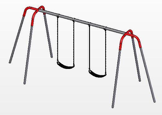
22 INSTALLATION INSTRUCTION BEFORE YOU BEGIN In addition to the components on the packing list you will need a tape measure, post hole digger, level and a dry erase marker. INSTALLATION STEPS 1) Review all instructions before beginning: 2) Unpack, organize, and identify all components: Be sure to place all painted components on a protective surface (cardboard, cloth, etc ) to prevent damage. 3) Assemble Swing Frame: Layout parts so that when frame is erected, legs will be in approximately correct position. Assemble swing frame on side, on ground. If more than one section, assemble section by section. 4) Attach Swing End to Legs: To do this you will need four 2 3/8 x 11 pipe (2), two swing end fittings (1). Place the swing legs into the swing end fittings and tighten set screws. See (Detail A) 5) Attaching Middle Post to Swing End: You will need one 3 1/2 x 11 pipe (3), slide the pipe over the swing end fitting and secure it with the set screws. See (Detail B). September 11,
23 INSTALLATION INSTRUCTION INSTALLATION STEPS CONTIUDE 6) Attaching Swing Hangers: You will need four swing hangers (4), four D Shackles (7), four 4/O Chain (6). Assemble the D- shackles and chain to the swing hangers. Attach the swing hangers to the top rail following spacing on page 4. See (Detail C). 7) Attaching Seats: To attach seats to the chain. You will need the two cut proof seats (5), four of the D shackles (7). Use the D shackles and hook the chain and the cut proof belt seat to it. Make sure the bolt is down towards the belt seat. Then tighten the bolt that holds the chain and seat. See (Detail D). 8) Dig footing holes: Footing holes may be marked out and dug from footing layout; however, it is easier to position swing in proper location, mark holes, move swing aside, and dig holes. 9) Stand swing upright onto legs and brace in footing holes so that 2 3 of pipe will be under intended level of resilient surfacing and the top rail is at desired height. Plumb and level entire unit. Tighten all set screws. 10) Once the entire playground has been installed and you have verified that the entire playground is level you can add the concrete to the footing holes. Be sure to use concrete with a minimum 2,500 psi and mix the concrete per the manufacturer s directions before you pour it into the footing hole. Once the footing has been filled with concrete you should rope of the area for a minimum of 48 hours to allow the concrete set properly. September 11,
24 INSTALLATION INSTRUCTION INSTALLATION STEPS CONTINUED 11) Once the concrete has set, back fill dirt over the footing holes; inspect the area and components for tools, hazardous debris and sharp edges. Verify all components are installed and all hardware is tight and then install the safety surfacing. 12) Inspect the components: for sharp edges and if necessary file them down and apply touch up paint. September 11,
H 12 Heavy Duty Modern Tripod 8 Seat Swing Heavy Duty Hangers
 Page 1 IMPORTANT Please retain this instruction sheet in your files. It contains important replacement parts information. All equipment should be installed in accordance with these instructions. It is
IMPORTANT. Use of safety surfacing (wood mulch) in compliance with ASTM specification F1292 is required. WARNING
 in compliance with ASTM specification F1292 is required. WARNING") INSTALLATION DETAILS Recommended crew (Adult): 2-3 Installation time: 8-12 Hours not including concrete cure time User age: 5-12 Use zone: 22 Diameter Weight: 990 Actual Dimension: 120 Diameter MAINTENANCE:
INSTALLATION DETAILS Recommended crew (Adult): 2-3 Installation time: 8-12 Hours not including concrete cure time User age: 5-12 Use zone: 22 Diameter Weight: 990 Actual Dimension: 120 Diameter MAINTENANCE:
6 Tunnel Slide O rder # Modular Structure Installation Booklet
 6 Tunnel Slide O rder # Modular Structure Installation Booklet Tool and Material Checklist To dig holes, the best method is a tractor with an auger. Use a 12 auger bit. No matter what you use, there
WARNING- THIS EQUIPMENT IS DESIGNED FOR ADULTS ONLY. ONLY HEALTHY PEOPLE AGES 13 AND UP SHOULD USE THE EQUIPMENT.
 INSTALLATION DETAILS Recommended crew (Adult): 2 Installation time: 2 hours (plus time for concrete to cure) User age: 13 and up Weight: 163 lbs MAINTENANCE: As the owner of the equipment you are responsible
Installation Instructions
 Installation Instructions Installation Instructions Playworld Systems Models ZZXX0059, ZZXX0060, and ZZXX0061 Diggables Installation Preparation Recommended Crew:... Two (2) adults Installation Time:...
Model # 362S-RDP. 9/17/2012 Page 1 of 12
 Model # 362S-RDP 9/17/2012 Page 1 of 12 9/17/2012 Page 2 of 12 1675 Locust Street Red Bud, IL 62278 Phone: 618-282-8200 Fax: 618-282-8202 WARRANTY & TERMS WARRANTY: 5 Year Limited Warranty on Thermoplastic
Model # 800SM-PS3. 8/3/2016 Page 1 of 8
 Model # 800SM-PS3 8/3/2016 Page 1 of 8 /3/2016 Page 2 of 8 1675 Locust Street Red Bud, IL 62278 Phone: 618-282-8200 Fax: 618-282-8202 WARRANTY & TERMS WARRANTY: 5 Year Limited Warranty on Thermoplastic
FITNESS PLAYGROUND ITEM NO: 8010
 FITNESS PLAYGROUND ITEM NO: 8010 OWNER S MANUAL CAUTION: This unit is designed to be used safely by up to 4 children between the ages of 3 years to 8 years old with a maximum weight of 100 pounds (45.4
Model # 940S-P6-BB. 6/7/2017 Page 1 of 10
 Model # 940S-P6-BB 6/7/2017 Page 1 of 10 /7/2017 Page 2 of 10 1675 Locust Street Red Bud, IL 62278 Phone: 618-282-8200 Fax: 618-282-8202 WARRANTY & TERMS WARRANTY: 5 Year Limited Warranty on Thermoplastic
Model # 815P-VCA3. 3/31/2011 Page 1 of 10
 Model # 815P-VCA3 3/31/2011 Page 1 of 10 3/31/2011 Page 2 of 10 1675 Locust Street Red Bud, IL 62278 Phone: 618-282-8200 Fax: 618-282-8202 WARRANTY & TERMS WARRANTY: 5 Year Limited Warranty on Thermoplastic
Model # 338S-PR. 5/1/2014 Page 1 of 12
 Model # 338S-PR 5/1/2014 Page 1 of 12 /1/2014 Page 2 of 12 1675 Locust Street Red Bud, IL 62278 Phone: 618-282-8200 Fax: 618-282-8202 WARRANTY & TERMS WARRANTY: 5 Year Limited Warranty on Thermoplastic
Meadow Park Site Improvements APPENDIX A PLAY EQUIPMENT INFORMATION AND INSTALLATION
 Meadow Park Site Improvements APPENDIX A PLAY EQUIPMENT INFORMATION AND INSTALLATION MEADOW PARK WILLAMALANE SITE PLAN ADA ACCESSIBILITY GUIDELINE - ADAAG CONFORMANCE ELEVATED ACCESSIBLE RAMP ACCESSIBLE
Model # 158-P4. 12/12/2013 Page 1 of 11
 Model # 158-P4 12/12/2013 Page 1 of 11 2/12/2013 Page 2 of 11 1675 Locust Street Red Bud, IL 62278 Phone: 618-282-8200 Fax: 618-282-8202 WARRANTY & TERMS WARRANTY: 5 Year Limited Warranty on Thermoplastic
Model # 338S-P. 7/31/2012 Page 1 of 13
 Model # 338S-P 7/31/2012 Page 1 of 13 7/31/2012 Page 2 of 13 1675 Locust Street Red Bud, IL 62278 Phone: 618-282-8200 Fax: 618-282-8202 WARRANTY & TERMS WARRANTY: 5 Year Limited Warranty on Thermoplastic
Model #369S-PR. 8/23/2016 Page 1 of 11
 Model #369S-PR 8/23/2016 Page 1 of 11 /23/2016 Page 2 of 11 1675 Locust Street Red Bud, IL 62278 Phone: 618-282-8200 Fax: 618-282-8202 WARRANTY & TERMS WARRANTY: 5 Year Limited Warranty on Thermoplastic
Model # 504S-P. 9/14/2011 Page 1 of 9
 Model # 504S-P 9/14/2011 Page 1 of 9 9/14/2011 Page 2 of 9 1675 Locust Street Red Bud, IL 62278 Phone: 618-282-8200 Fax: 618-282-8202 WARRANTY & TERMS WARRANTY: 5 Year Limited Warranty on Thermoplastic
Model # 238HS-P8. 4/27/2011 Page 1 of 11
 Model # 238HS-P8 4/27/2011 Page 1 of 11 4/27/2011 Page 2 of 11 1675 Locust Street Red Bud, IL 62278 Phone: 618-282-8200 Fax: 618-282-8202 WARRANTY & TERMS WARRANTY: 5 Year Limited Warranty on Thermoplastic
Model # 338S-RDP. 7/31/2012 Page 1 of 13
 Model # 338S-RDP 7/31/2012 Page 1 of 13 7/31/2012 Page 2 of 13 1675 Locust Street Red Bud, IL 62278 Phone: 618-282-8200 Fax: 618-282-8202 WARRANTY & TERMS WARRANTY: 5 Year Limited Warranty on Thermoplastic
1675 Locust Street Red Bud, IL Phone: Fax: WARRANTY & TERMS
 Model # 349S-P6 1675 Locust Street Red Bud, IL 62278 Phone: 618-282-8200 Fax: 618-282-8202 WARRANTY & TERMS WARRANTY: 5 Year Limited Warranty on Thermoplastic coated elements. Ultra Play guarantees all
Model #369S-RDP. 8/23/2016 Page 1 of 11
 Model #369S-RDP 8/23/2016 Page 1 of 11 /23/2016 Page 2 of 11 1675 Locust Street Red Bud, IL 62278 Phone: 618-282-8200 Fax: 618-282-8202 WARRANTY & TERMS WARRANTY: 5 Year Limited Warranty on Thermoplastic
Model # 358-OP. 8/5/2014 Page 1 of 12
 Model # 358-OP 8/5/2014 Page 1 of 12 /5/2014 Page 2 of 12 1675 Locust Street Red Bud, IL 62278 Phone: 618-282-8200 Fax: 618-282-8202 WARRANTY & TERMS WARRANTY: 5 Year Limited Warranty on Thermoplastic
Model # V. 1/31/2014 Page 1 of 8
 Model # 110-16V 1/31/2014 Page 1 of 8 /31/2014 Page 2 of 8 1675 Locust Street Red Bud, IL 62278 Phone: 618-282-8200 Fax: 618-282-8202 WARRANTY & TERMS WARRANTY: 5 Year Limited Warranty on Thermoplastic
Model # 358PS-OP. 12/13/2013 Page 1 of 12
 Model # 358PS-OP 12/13/2013 Page 1 of 12 2/13/2013 Page 2 of 12 1675 Locust Street Red Bud, IL 62278 Phone: 618-282-8200 Fax: 618-282-8202 WARRANTY & TERMS WARRANTY: 5 Year Limited Warranty on Thermoplastic
Model # 338SM-OP. 9/30/2011 Page 1 of 12
 Model # 338SM-OP 9/30/2011 Page 1 of 12 9/30/2011 Page 2 of 12 1675 Locust Street Red Bud, IL 62278 Phone: 618-282-8200 Fax: 618-282-8202 WARRANTY & TERMS WARRANTY: 5 Year Limited Warranty on Thermoplastic
Model # 358PS-RDP. 12/13/2013 Page 1 of 12
 Model # 358PS-RDP 12/13/2013 Page 1 of 12 2/13/2013 Page 2 of 12 1675 Locust Street Red Bud, IL 62278 Phone: 618-282-8200 Fax: 618-282-8202 WARRANTY & TERMS WARRANTY: 5 Year Limited Warranty on Thermoplastic
Model # 357-MC. 8/13/2018 Page 1 of 12
 Model # 357-MC 8/13/2018 Page 1 of 12 /13/2018 Page 2 of 12 1675 Locust Street Red Bud, IL 62278 Phone: 618-282-8200 Fax: 618-282-8202 WARRANTY & TERMS WARRANTY: 5 Year Limited Warranty on Thermoplastic
Model #369SM-RDP. 8/23/2016 Page 1 of 10
 Model #369SM-RDP 8/23/2016 Page 1 of 10 /23/2016 Page 2 of 10 1675 Locust Street Red Bud, IL 62278 Phone: 618-282-8200 Fax: 618-282-8202 WARRANTY & TERMS WARRANTY: 5 Year Limited Warranty on Thermoplastic
Model # 238-U6. 5/24/2013 Page 1 of 11
 Model # 238-U6 5/24/2013 Page 1 of 11 /24/2013 Page 2 of 11 1675 Locust Street Red Bud, IL 62278 Phone: 618-282-8200 Fax: 618-282-8202 WARRANTY & TERMS WARRANTY: 5 Year Limited Warranty on Thermoplastic
Model # 358H-PR. 4/8/2011 Page 1 of 12
 Model # 358H-PR 4/8/2011 Page 1 of 12 4/8/2011 Page 2 of 12 1675 Locust Street Red Bud, IL 62278 Phone: 618-282-8200 Fax: 618-282-8202 WARRANTY & TERMS WARRANTY: 5 Year Limited Warranty on Thermoplastic
Model #967- S6. 7/7/2016 Page 1 of 14
 Model #967- S6 7/7/2016 Page 1 of 14 /7/2016 Page 2 of 14 1675 Locust Street Red Bud, IL 62278 Phone: 618-282-8200 Fax: 618-282-8202 WARRANTY & TERMS WARRANTY: 5 Year Limited Warranty on Thermoplastic
Model # BT238-U6. 9/30/2014 Page 1 of 12
 Model # BT238-U6 9/30/2014 Page 1 of 12 /30/2014 Page 2 of 12 1675 Locust Street Red Bud, IL 62278 Phone: 618-282-8200 Fax: 618-282-8202 WARRANTY & TERMS WARRANTY: 5 Year Limited Warranty on Thermoplastic
Model # 338S-OP. 9/30/2011 Page 1 of 13
 Model # 338S-OP 9/30/2011 Page 1 of 13 9/30/2011 Page 2 of 13 1675 Locust Street Red Bud, IL 62278 Phone: 618-282-8200 Fax: 618-282-8202 WARRANTY & TERMS WARRANTY: 5 Year Limited Warranty on Thermoplastic
Model # 940PPS-V3. 2/12/2014 Page 1 of 10
 Model # 940PPS-V3 2/12/2014 Page 1 of 10 /12/2014 Page 2 of 10 1675 Locust Street Red Bud, IL 62278 Phone: 618-282-8200 Fax: 618-282-8202 WARRANTY & TERMS WARRANTY: 5 Year Limited Warranty on Thermoplastic
Playground Review and Maintenance Process
 Playground Review and Maintenance Process Line of Business: General Liability Risk Control Strategy/Key Issues: Establish procedures for existing playground equipment review to comply with current safety
SCHOOL BUS CONTAINED PLAY INSTALLATION INSTRUCTION
 INSTALLATION DETAILS! Recommended crew (Adult): 2! Installation time: 4-8 Hours (8-16 total man hours)! User age: 2-5 Years! Use zone: 9 3 x 5 11! Weight: 1,700 MAINTENANCE As the owner of the play equipment
Model # 95-S8. Page 1 of 8
 Model # 95-S8 Page 1 of 8 Page 2 of 8 WARRANTY & TERMS WARRANTY: 5 Year Limited Warranty on Thermoplastic coated elements. Ultra Play guarantees all items for one full year to be free of defects in workmanship
Model # 358-R48. 7/7/2011 Page 1 of 11
 Model # 358-R48 7/7/2011 Page 1 of 11 7/7/2011 Page 2 of 11 1675 Locust Street Red Bud, IL 62278 Phone: 618-282-8200 Fax: 618-282-8202 WARRANTY & TERMS WARRANTY: 5 Year Limited Warranty on Thermoplastic
Minimo Product Specification Rotationally Molded Plastics All Rotationally Molded Products are manufactured from Low density polyethylene with U
 Minimo - 3.5 Product Specification Rotationally Molded Plastics All Rotationally Molded Products are manufactured from Low density polyethylene with UV-stabilized color. The tensile strength of this material
Model # 922-S4. 12/18/2013 Page 1 of 8
 Model # 922-S4 12/18/2013 Page 1 of 8 2/18/2013 Page 2 of 8 1675 Locust Street Red Bud, IL 62278 Phone: 618-282-8200 Fax: 618-282-8202 WARRANTY & TERMS WARRANTY: 5 Year Limited Warranty on Thermoplastic
1675 Locust Street Red Bud, IL Phone: Fax: WARRANTY & TERMS
 Model # 347SM-V8 1675 Locust Street Red Bud, IL 62278 Phone: 618-282-8200 Fax: 618-282-8202 WARRANTY & TERMS WARRANTY: 5 Year Limited Warranty on Thermoplastic coated elements. Ultra Play guarantees all
Model # 940SM-P8. Page 1 of 10
 Model # 940SM-P8 Page 1 of 10 Page 2 of 10 WARRANTY & TERMS WARRANTY: 5 Year Limited Warranty on Thermoplastic coated elements. Ultra Play guarantees all items for one full year to be free of defects in
EASY RIDER (MUSTANG) EASY RIDER (PONY) EASY RIDER (ZEBRA) EASY RIDER (BRONCO)
 EASY RIDER (PONY) EASY RIDER (ZEBRA) EASY RIDER (BRONCO)") Page 1 * IMPORTANT * PLEASE RETAIN THIS INSTRUCTION SHEET IN YOUR FILES. IT CONTAINS IMPORTANT REPLACEMENT PARTS INFORMATION. ALL EQUIPMENT SHOULD BE INSTALLED IN ACCORDANCE WITH THESE INSTRUCTIONS. IT
Page 1 * IMPORTANT * PLEASE RETAIN THIS INSTRUCTION SHEET IN YOUR FILES. IT CONTAINS IMPORTANT REPLACEMENT PARTS INFORMATION. ALL EQUIPMENT SHOULD BE INSTALLED IN ACCORDANCE WITH THESE INSTRUCTIONS. IT
Model # 940SM-V8. Page 1 of 10
 Model # 940SM-V8 Page 1 of 10 Page 2 of 10 WARRANTY & TERMS WARRANTY: 5 Year Limited Warranty on Thermoplastic coated elements. Ultra Play guarantees all items for one full year to be free of defects in
Model # BARK /26/2012 Page 1 of 5
 Model # BARK-430 6/26/2012 Page 1 of 5 6/26/2012 Page 2 of 5 1675 Locust Street Red Bud, IL 62278 Phone: 618-282-8200 Fax: 618-282-8202 WARRANTY & TERMS WARRANTY: 5 Year Limited Warranty on Thermoplastic/Canine
Model # BARK-358-RDP
 Model # BARK-358-RDP 1675 Locust Street Red Bud, IL 62278 Phone: 618-282-8200 Fax: 618-282-8202 WARRANTY & TERMS WARRANTY: 5 Year Limited Warranty on Thermoplastic/Canine coated elements. guarantees all
Installation Instructions
 Installation Instructions Installation Instructions Universal Model UN4448 Free Standing Adventure Crawl Tube Installation Preparation Recommended Crew:...Two (2) adults Installation Time:...3 man-hours
1675 Locust Street Red Bud, IL Phone: Fax: WARRANTY & TERMS
 Model # BARK-420 1675 Locust Street Red Bud, IL 62278 Phone: 618-282-8200 Fax: 618-282-8202 WARRANTY & TERMS WARRANTY: 5 Year Limited Warranty on Thermoplastic/Canine coated elements. guarantees all items
Model # PR /21/2018 Page 1 of 10
 Model # PR-32 11/21/2018 Page 1 of 10 1/21/2018 Page 2 of 10 1675 Locust Street Red Bud, IL 62278 Phone: 618-282-8200 Fax: 618-282-8202 WARRANTY & TERMS WARRANTY: 5 Year Limited Warranty on Thermoplastic
Model # 964-S6. 2/3/2015 Page 1 of 8
 Model # 964-S6 2/3/2015 Page 1 of 8 /3/2015 Page 2 of 8 1675 Locust Street Red Bud, IL 62278 Phone: 618-282-8200 Fax: 618-282-8202 WARRANTY & TERMS WARRANTY: 5 Year Limited Warranty on Thermoplastic coated
Instructions for 12 IGT system
 Instructions for 12 IGT system Step 1: IGT Site Preparation Site Location Several factors must be considered when choosing the site for your new In-Ground Trampoline (IGT) system. Since local soil and
1675 Locust Street Red Bud, IL Phone: Fax: WARRANTY & TERMS
 Model # BARK-470 1675 Locust Street Red Bud, IL 62278 Phone: 618-282-8200 Fax: 618-282-8202 WARRANTY & TERMS WARRANTY: 5 Year Limited Warranty on Thermoplastic/Canine coated elements. guarantees all items
Model # 5803SM. 6/15/2018 Page 1 of 5
 Model # 5803SM 6/15/2018 Page 1 of 5 6/15/2018 Page 2 of 5 1675 Locust Street Red Bud, IL 62278 Phone: 618-282-8200 Fax: 618-282-8202 WARRANTY & TERMS WARRANTY: 5 Year Limited Warranty on Thermoplastic
Installation Instructions
 Installation Instructions Installation Instructions Playworld Systems Accessible EZ Digger Installation Preparation Recommended Crew:...One (1) adult Installation Time:...1 hour Required:...0.11 cubic
Natural Balance Beam, Straight #7014
 A Collaborative Program of Arbor Day Foundation and Dimensions Educational Research Foundation Natural Balance Beam, Straight #7014 Assembly Instructions Please open and inspect all items upon receipt.
Model # 600H-D. 4/2/2012 Page 1 of 6
 Model # 600H-D 4/2/2012 Page 1 of 6 4/2/2012 Page 2 of 6 1675 Locust Street Red Bud, IL 62278 Phone: 618-282-8200 Fax: 618-282-8202 WARRANTY & TERMS WARRANTY: 5 Year Limited Warranty on Thermoplastic coated
Model # 612H. 7/11/2016 Page 1 of 6
 Model # 612H 7/11/2016 Page 1 of 6 /11/2016 Page 2 of 6 1675 Locust Street Red Bud, IL 62278 Phone: 618-282-8200 Fax: 618-282-8202 WARRANTY & TERMS WARRANTY: 5 Year Limited Warranty on Thermoplastic coated
Model # 91-S6. 6/19/2014 Page 1 of 5
 Model # 91-S6 6/19/2014 Page 1 of 5 /19/2014 Page 2 of 5 1675 Locust Street Red Bud, IL 62278 Phone: 618-282-8200 Fax: 618-282-8202 WARRANTY & TERMS WARRANTY: 5 Year Limited Warranty on Thermoplastic coated
Model # SV-R32AU. 2/13/2015 Page 1 of 11
 Model # SV-R32AU 2/13/2015 Page 1 of 11 /13/2015 Page 2 of 11 1675 Locust Street Red Bud, IL 62278 Phone: 618-282-8200 Fax: 618-282-8202 WARRANTY & TERMS WARRANTY: 5 Year Limited Warranty on Thermoplastic
PRODUCT INFORMATION Dero Hoop Rack
 PRODUCT INFORMATION Dero Hoop Rack 2946 Larimer St. Denver, CO 80205 303-295-1100 / 800-373-7693 FAX 303-295-2464 Email info@snyderequipment.com www.snyderequipment.com H O O P R A C K The Hoop Rack is
Thanks again & remember to tell your friends about your product from Component Playgrounds!
 Dear Customer: Thank you for purchasing your equipment from Component Playgrounds!!! We are proud of our commercial grade products made for kids of all ages & sizes, and we are confident that you will
Model #CL-36FT. 6/22/2017 Page 1 of 6
 Model #CL-36FT 6/22/2017 Page 1 of 6 /22/2017 Page 2 of 6 1675 Locust Street Red Bud, IL 62278 Phone: 618-282-8200 Fax: 618-282-8202 WARRANTY & TERMS WARRANTY: 5 Year Limited Warranty on Thermoplastic
Thanks again & remember to tell your friends about your product from Component Playgrounds!
 Dear Customer: Thank you for purchasing your equipment from Component Playgrounds!!! We are proud of our commercial grade products made for kids of all ages & sizes, and we are confident that you will
A Collaborative Program of Arbor Day Foundation and Dimensions Educational Research Foundation. Tube Drums #7000. Assembly Instructions
 A Collaborative Program of Arbor Day Foundation and Dimensions Educational Research Foundation Tube Drums #7000 Assembly Instructions Please open and inspect all items upon receipt. If you have any questions
Installation Instructions
 Installation Instructions Playworld Systems Whirligig Installation Preparation Recommended Crew:... Two (2) adults Installation Time:... 3 man-hours Concrete Required:... 0.13 cubic yard (0,10 cubic meters)
Instructions for 12 and 15 IGT systems (12 pictured)
") Instructions for 12 and 15 IGT systems (12 pictured) Step 1: IGT Site Preparation Site Location Several factors must be considered when choosing the site for your new In-Ground Trampoline (IGT) system.
Instructions for 12 and 15 IGT systems (12 pictured) Step 1: IGT Site Preparation Site Location Several factors must be considered when choosing the site for your new In-Ground Trampoline (IGT) system.
PE45 AMAZON MONKEY BARS OWNER'S MANUAL
 PE45 AMAZON MONKEY BARS OWNER'S MANUAL WARNING! The disassembled product may contain small parts which pose a choking hazard to children under 3. IMPORTANT: This product may contain sharp points and small
MODEL # MSC-4120-BM. Spring Breeze with Me and My Toddler Metal Swing Chair OWNER S MANUAL
 MODEL # MSC-4120-BM Spring Breeze with Me and My Toddler Metal Swing Chair OWNER S MANUAL ASSEMBLY, INSTALLATION, CARE, MAINTENANCE AND USER INSTRUCTIONS FOR RESIDENTIAL USE ONLY WARNING This product is
Heartland Perma-Column 1841 E 1450 Rd. Lawrence, KS (785)
") Perma-Column Installation Instructions Unlike any other concrete post-frame foundation system, Perma-Column Precast Concrete Piers use 10,000 psi concrete and our unique Sturdi-Wall Plus wet-set bracket
Perma-Column Installation Instructions Unlike any other concrete post-frame foundation system, Perma-Column Precast Concrete Piers use 10,000 psi concrete and our unique Sturdi-Wall Plus wet-set bracket
FitTech UP171F ELLIPTICAL (FOOTING) UP171I ELLIPTICAL (IN GROUND) UP171S ELLIPTICAL (SURFACE) Parts List
 UP171I ELLIPTICAL (IN GROUND) UP171S ELLIPTICAL (SURFACE) Parts List") ELLIPTICAL BASE COVER DESCRIPTION FOOTBUCK WELD ASS'Y HARDWARE COMPLETE HARDWARE COMPLETE HARDWARE COMPLETE /" ANCHOR ROD 3/" x " HEX HEAD CAP SCREW 3/" WEDGE ANCHOR 3/" ANCHOR BOLT 3/" FLATWASHER (" O.D.)
ELLIPTICAL BASE COVER DESCRIPTION FOOTBUCK WELD ASS'Y HARDWARE COMPLETE HARDWARE COMPLETE HARDWARE COMPLETE /" ANCHOR ROD 3/" x " HEX HEAD CAP SCREW 3/" WEDGE ANCHOR 3/" ANCHOR BOLT 3/" FLATWASHER (" O.D.)
2/24/2015 Page 1 of 5
 2/24/2015 Page 1 of 5 2/ 24/ 2015 Page 2 o f 5 WARRANTY & TERMS WARRANTY: 5 Year Limited Warranty on Thermoplastic/Canine coated elements. Guarantees all items for one full year to be free of defects in
1675 Locust Street Red Bud, IL Phone: Fax: WARRANTY & TERMS
 Model # BARK-480 1675 Locust Street Red Bud, IL 62278 Phone: 618-282-8200 Fax: 618-282-8202 WARRANTY & TERMS WARRANTY: 5 Year Limited Warranty on Thermoplastic/Canine coated elements. Bark Park guarantees
FitTech UP166F CHEST PRESS (FOOTING) UP166I CHEST PREES (IN GROUND) UP166S CHEST PRESS (SURFACE)
 UP166I CHEST PREES (IN GROUND) UP166S CHEST PRESS (SURFACE)") CHEST PRESS BASE COVER DESCRIPTION FOOTBUCK WELD ASSEMBLY HARDWARE COMPLETE HARDWARE COMPLETE HARDWARE COMPLETE /" ANCHOR ROD 3/" x " HEX HEAD CAP SCREW 3/" WEDGE ANCHOR 3/" ANCHOR BOLT 3/" FLATWASHER
CHEST PRESS BASE COVER DESCRIPTION FOOTBUCK WELD ASSEMBLY HARDWARE COMPLETE HARDWARE COMPLETE HARDWARE COMPLETE /" ANCHOR ROD 3/" x " HEX HEAD CAP SCREW 3/" WEDGE ANCHOR 3/" ANCHOR BOLT 3/" FLATWASHER
Highlander. Owner s Manual And Assembly Instructions
 Highlander Owner s Manual And Assembly Instructions Highlander Thank you for purchasing an Highlander Playcenter. We hope it will bring you and your children many years of safe and enjoyable backyard fun.
COPYRIGHT 2001 BY: GAMETIME REVISED: 08/09/01
 COPYRIGHT 2 BY: GAMETIME REVISED: 8/9/ 627 FITKID PARALLEL BAR NOTE: 627 2'-6" PARALLEL BAR 628 3' PARALLEL BAR 629 3'-" PARALLEL BAR 63 3'-6" PARALLEL BAR 63 3'-" PARALLEL BAR 632 '-2" PARALLEL BAR 633
 Instruction Manual Span Scaffolds! W A R N I N G! Before using Instant UpRight Scaffolds, read, understand and follow all Safety Rules, Erection Instructions and Maintenance Rules. Keep this manual for
PE57 HOLT 2 DOUBLE SWING OWNER S MANUAL
 PE57 HOLT 2 DOUBLE SWING OWNER S MANUAL - Not suitable for children under 36 months due to small parts, cords and the design of the product. - For children ages 3-12 years and must be used under adult
To Contact PS DOORS:
 MODELS Stainless Steel (SS) Powder Coat Yellow (PCY) Hot Dipped Galvanized (GAL) TABLE OF CONTENTS PAGE Warranty Information General Paired LSG Information Installing the Support Channels 3 Installing
Instruction Manual Span Scaffolds
 Instruction Manual Span Scaffolds QUALITY & STRENGTH YOU CAN TRUST! W A R N I N G! Before using Instant UpRight Scaffolds, read, understand and follow all Safety Rules, Erection Instructions and Maintenance
GROUND MOUNT INSTALLATION MANUAL
 GROUND MOUNT INSTALLATION MANUAL Contents DISCLAIMER 1 CHECKLIST 2 1. ERECT BASe 3 2. CONNECT PIPES 3 3. PLACE RAILS 4 4. SECURE LUGS 4 5. CLAMP MODULES 5 DIAGONAL BRACES (OPTIONAL) 6 UNDER CLAMPS (OPTIONAL)
JUNGLE CONTAINED PLAY INSTALLATION INSTRUCTIONS 1
 WWW.SPORTSPLAYINC.COM 1 TOP DOWN VIEW SIDE VIEW WWW.SPORTSPLAYINC.COM 2 Bird/ PANEL 1 PANEL 2 PANEL 3 PANEL 4 PANEL 5 PANEL 6 PANEL 7 PANEL 8 WWW.SPORTSPLAYINC.COM 3 902-795 JUNGLE CONTAINED PLAY PANEL
Playground Maintenance Handbook MIRACLE DESIGNING PLAY
 Playground Maintenance Handbook Playground Maintenance Checklist Location: Inspected By: Date: Time: OK Not Condition Recommendation/ Action Taken OK Survey area for dangerous trash such as, large rocks,
PE21 AMBER DOUBLE SWING OWNER S MANUAL
 PE21 AMBER DOUBLE SWING OWNER S MANUAL - Not suitable for children under 36 months due to small parts, cords and the design of the product. - For children ages 3-12 and must be used under adult supervision.
GroundTrac. Installation Manual
 APPLICATION: The GroundTrac system is designed with a minimum amount of installed footings at greatly reduced labor. The system integrates with ordinary 1-1/2 schedule #40 galvanized water pipe. This ground
PORTABLE GARAGE CAR CANOPY
 PORTABLE GARAGE CAR CANOPY 40544 ASSEMBLY INSTRUCTIONS 3491 Mission Oaks Blvd., Camarillo, CA 93011 Copyright 1999 by Harbor Freight Tools. All rights reserved. No portion of this manual or any artwork
VERsacourt LED Light System Installation Instructions
 VERsacourt LED Light System Installation Instructions PART LIST TEE BAR ASSEMBLY 10 12 LIGHT ASSEMBLY (hardware included) EXTENSION COLLAR BASE POLE EXTENSION POLE ANCHOR PAGE 1 REQUIRED TOOLS AND MATERIALS
PV Mounting System 2703 SERIES 200 UL GROUND MOUNT SYSTEM. SnapNrack Residential PV Mounting Systems Code Compliant Installation Manual
 PV Mounting System 2703 SERIES 200 UL GROUND MOUNT SYSTEM SnapNrack Residential PV Mounting Systems Code Compliant Installation Manual Series 200 UL Introduction Series 200 UL Introduction SnapNrack Series
SECTION 1208 CHAIN LINK FENCING DESCRIPTION
 SECTION 1208 CHAIN LINK FENCING 1208-1 DESCRIPTION This item covers the requirements for furnishing materials and constructing new chain link fences and gates in accordance with the details included herein
WARNING! Please follow all these Safety, Maintenance and Assembly Instructions. Failure to do so could result in serious or fatal injury.
 HERACLES SEESAW INSTRUCTION MANUAL No. 8035 Ages: 3-8 DO NOT DISCARD: IMPORTANT LITERATURE. PLEASE READ & FOLLOW INSTRUCTIONS CAREFULLY BEFORE ASSEMBLY AND USE OF THIS PRODUCT. PLEASE KEEP THIS INSTRUCTION
SK2000 Boltless Pallet Rack Installation and Assembly Manual
 SK2000 Boltless Pallet Rack Installation and Assembly Manual Steel King Industries, Inc. 2700 Chamber St Stevens Pont, WI 54481 (800) 826 0203 www.steelking.com info@steelking.com ASSEMBLY INSTRUCTIONS:
INSTALLATION GUIDE PLEASE READ ENTIRE INSTRUCTION MANUAL BEFORE PROCEEDING!
 DURA - TRENCH INSTALLATION GUIDE This guide is intended to aide in the installation of Dura-Trench systems. There are many different applications and situations for the use of this product and the installation
PATENTS ARE PENDING. Building Dimensions. Exterior Dimensions Roof Edge to Roof Edge
 Assembly Manual 8x5 PATENTS ARE PENDING Approximate Size 7980303 Storage Area Building Dimensions Exterior Dimensions Roof Edge to Roof Edge Interior Dimensions Wall to Wall Sq. Ft. Cu. Ft. Width Depth
Unirac Code-Compliant Installation Manual
 Planning and Assembly Installer responsibility The installer is solely responsible for: Complying with all local or national building codes, including any that may supercede this manual. Ensuring that
Installation Manual. ArchCast Bridge. 3-Sided Precast Concrete Bridge Structure
 ArchCast Bridge 3-Sided Precast Concrete Bridge Structure Installation Manual Salem Location: 749 West Commercial Ave. Salem, IL 62881 (618) 548-1190 countymaterials.com Email: info@countymaterials.com
MAINTENANCE MANUAL. IMPORTANT! This manual contains maintenance, safety and repair information
 MAINTENANCE MANUAL IMPORTANT! This manual contains maintenance, safety and repair information WARNING: Read this manual thoroughly before installation. Improper assembled or maintained playground equipment
PATENTS ARE PENDING. Building Dimensions. Exterior Dimensions Roof Edge to Roof Edge
 Assembly Manual 8x9 PATENTS ARE PENDING Approximate Size 7640303 Storage Area Building Dimensions Exterior Dimensions Roof Edge to Roof Edge Interior Dimensions Wall to Wall Sq. Ft. Cu. Ft. Width Depth
Community Services Dept., City of Mississauga Subdivision Requirements Manual Page 1 of 11 Specifications Revised: January 31, 2003
 Subdivision Requirements Manual Page 1 of 11 PART I - GENERAL 1.1 Related Work.1 Playground Sand : Section 02861.2 Topsoil and Finish Grading : Section 02212.3 Sodding : Section 02938 1.2 Scope of Work.1
Freedom Barrier Free Shower Pan Installation Instructions
 Tools & Materials you might need for proper installation Materials: 2-1 gallon buckets of solid wood flooring adhesive (non-shrink) or 100% silicone adhesive 20-1.25 wood screws 1 - tube of non-shrink
Freedom Barrier Free Shower Pan Installation Instructions
 Tools & Materials you might need for proper installation Materials: 2-1 gallon buckets of solid wood flooring adhesive (non-shrink) or 100% silicone adhesive 20-1.25 wood screws 1 - tube of non-shrink
Deck Design Mike & Melissa Deck Option #02
 Deck Design Mike & Melissa Deck Option #02 Congratulations! You just completed your Trex deck design. This report will provide the following information: Deck Layout Diagrams Basic Installation Tips Deck