PACIFIC SHORING, LLC ALUMINUM SHORING PRODUCTS PSH. TABULATED DATA Effective December 10, 2013 RED
|
|
|
- Calvin Rodgers
- 6 years ago
- Views:
Transcription


 575-9014")

1 1 Effective December 10, 2013 PSH Construction Engineering Resource 265 Roberts Avenue Santa Rosa, Ca (707) Wright Street Santa Rosa, Ca (707)
2 2 Contents Contents... 2 Description... 2 General Information for use of Pacific Shoring Modular Aluminum Buildable Box... 3 Classification of s... 5 Determining Buildable Box Shoring Configurations... 6 Buildable Box Components... 7 Determining Buildable Box Weight... 8 Geometric Properties for Engineering Design... 9 Allowable Buildable Box Wall Panel Spans Allowable Corner Post Spans Allowable Strut Lengths Buildable Box Medium Clearance Spreader Applications Buildable Box High Clearance Strut Applications Buildable Box Installation and Removal Safe Handling and Use of Buildable Box Shoring System Description The Pacific Shoring Modular Buildable Box is an aluminum shoring system consisting of 2'8" x 8" T&G panels, corner posts, and a strut system at the ends. The system can be constructed in 2 sided, 3 sided, and 4 sided configurations. The posts, panels, and struts are pinned in place. This allows construction and modification of the box at the site. Hydraulic aluminum struts are also available thereby allowing the buildable box system to become a hydraulic shoring system. The panel lengths are available from 3 ft to 16 ft long. Corner posts vary in length from 2 ft to 12 ft. Boxes may be stacked and have allowable depths to 25 ft. Additional depths may be achieved thru design by a registered engineer. Hand adjustable struts, static struts, and hydraulic struts adjusting to maximum 12 ft may be used with the system. Pacific Shoring also manufactures a medium high clearance strut and a high clearance strut for two and three sided boxes. A 4 sided configuration may be used up to 16 ft x16 ft. These boxes may be used in a static or dynamic configuration. A static configuration assumes that the box wall does not necessarily touch the sides of the excavation and that there is no pressure being exerted on the soil. A dynamic configuration requires that the shield walls are pressurized against the soil. Pressurization sets up soil arching and delivers some of the soil pressure directly to the corners and therefore results in less pressure on the box walls. With this configuration, slightly longer wall lengths can be achieved and the possibility of shoring wall collapse and surrounding existing facility damage can be prevented. This shoring system is generally used in utility work where differing conditions and excavation geometry occur on a daily basis. The system can be easily loaded onto a truck and constructed at the site as the excavation dimensions and obstructions reveal themselves. Parts may be handled by one person and constructed boxes can be handled with a backhoe.
3 3 General Information for use of Pacific Shoring Modular Aluminum Buildable Box 1. The buildable box shoring system tabulated here is based on requirements of Federal OSHA 29CFR, Part 1926, Subpart P-Excavations, and Trenches (c)(2)-Option (2) - Designs Using Manufacturer's Tabulated Data (c)(2)(i) -Design of support systems, shield systems, or other protective systems that are drawn from manufacturer's tabulated data shall be in accordance with all specifications, recommendations, and limitations issued or made by the manufacturer. All provisions of Subpart P apply when utilizing this tabulated data. The contractor s competent person shall use this data to select allowable trench depth, box wall, and strut configuration. The competent person utilizing this tabulated data shall be experienced and knowledgeable of all requirements of Subpart P, and trained in the use and safety procedures for shoring box applications. 2. Use of this tabulated data is dependent on first classifying the soil in accordance with OSHA Appendix A, Soil Classification. Classification shall be just prior to installing shoring box. Soil conditions may change at a later date and require revaluation of the strength and allowable depth. 3. Modular aluminum buildable boxes are tabulated based on the effect of a 20,000 lb surcharge load set back 2 ft from the edge of the trench and the equivalent weight effect of the OSHA soil type, see classification of soil types, The depth and spacing given in Tables 1, 2, and 3 governs the use of Pacific Shoring Buildable Boxes and not tabulations given by other manufacturers. This tabulated data applies to buildable boxes manufactured by Pacific Shoring, LLC; however, all parts are interchangeable with Speed- Shore Modular Aluminum Panel Shields, MAPS. Speed-Shore MAPS parts may be interchanged and used with Pacific Shoring Buildable Boxes under this tabulated data. Any alterations to the boxes or variance from this tabulated data shall be indicated in a site-specific plan prepared and approved by a registered engineer. 5. Faces of excavations shall be vertical and the shoring walls shall be within 12" of the excavation wall. 6. Aluminum Buildable Boxes may be stacked or longitudinally connected. 7. Aluminum Buildable Boxes shall be installed and removed from outside the trench, see installation and removal procedure. 8. The competent person shall continually monitor the shored excavation for changed conditions such as water seepage, soil movement cracks at the surface, sloughing or raveling, proper surcharge load weight less than 20,000 lbs and setback a minimum of 2 ft that may damage the shores. 9. Workers shall always enter, exit, and work inside the shored area of the trench.
4 4 10. Aluminum Buildable Boxes may be stacked as long as they are pinned together. 11. Aluminum Buildable Boxes may be set a maximum of 2 ft from the bottom of the excavation. The trench depth is the full distance to the bottom of the excavation.
5 5 Classification of s 1. Soil classification shall be in accordance with OSHA Appendix A and classified just prior to installing hydraulic vertical shores. Soil conditions may change at a later date and require hydraulic vertical shores to be reset at a different spacing. 2. The equivalent weight of OSHA soil types* is assumed to be as follows: OSHA Type A Soil 25 PSF per ft of depth OSHA Type B Soil 45 PSF per ft of depth Type C-60 Soil 60 PSF per ft of depth** OSHA Type C Soil 80 PSF per ft of depth * These equivalent weights were adapted from OSHA 1926 Subpart P App C, Timber Shoring for Trenches, Tables C-1.1, C-1.2, and C-1.3 ** Type C-60 soil is not identified or classified in OSHA Appendix A 3. Type C-60 soil is soil that does not qualify as OSHA Type A, or Type B, can be cut with vertical walls and will stand up long enough to safely insert and pressurize the hydraulic shore. 4. Buildable boxes may be used in C-80 soil provided they are dug into the excavation and not driven into the soil.
6 6 Determining Aluminum Buildable Box Shoring Configurations Shoring use and configurations shall be determined by the user (employer and designated competent person). The following steps are necessary to properly configure and construct a buildable box shoring system: 1. Define soil type in accordance with OSHA Appendix A 2. Determine surcharge loading. All shoring equipment is designed for a maximum of a 20,000 lb surcharge load set back 2 ft from the edge of the trench. Larger loads shall be set back further or reduced. The competent person shall have training and knowledge in proper determination of surcharge loads. 3. Determine length, width, and depth of shoring requirement. 4. Determine existing facilities and depths that they will enter into the shoring configuration. 5. Determine depths, locations, and clearance requirements of facilities that will be constructed inside the shoring. 6. Determine components of the Buildable Box system needed to fit the requirements of the system. These components will at a minimum consist of: Wall panels Corner posts Strutting for 2 and 3 sided boxes High clearance strutting for constructed facilities entering or exiting the shoring system 7. Determine allowable depths and settings for components as follows: a) Wall Panels - Table 1 - Allowable for Buildable Box wall Panels b) Corner posts - Table 2 - Allowable Corner Post Spans. Corner posts have an allowable cantilever span and allowable strut spacing span based on the depth of the excavation. These tables apply to hydraulic spreaders, pinned end struts, and screw jack struts. c) Struts - Table 3 - Allowable Strut Lengths d) High clearance strutting - Table 4 - Allowable using Medium High Clearance Spreader Table 5 - Allowable using High Clearance Spreader Note - The medium high clearance spreader allows more depth than the high clearance spreader 8. Determine approximate shoring system weight before rigging. Rigging equipment and connections should have a 5:1 factor of safety.

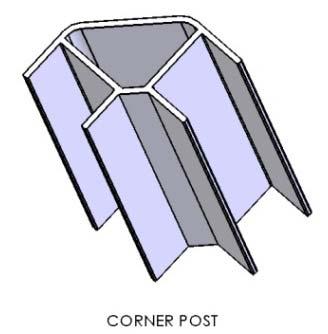
7 7 Buildable Box Components
8 8 Buildable Box components are manufactured in several different sizes that can then be pinned together in practically any size box. Sizes available are as follows: 2 ft wall panel 4 ft 6 ft 8 ft 10 ft 12 ft 16 ft Corner Post 2 ft 4 ft 8ft 10 ft 12 ft End Strut 4 ft to 6 ft 6 ft to 8 ft 8 ft to 12ft 12 ft to 16 ft Screw Jack Strut 4 ft to 6 ft 6 ft to 8 ft 8 ft to 12ft Custom Length Medium Clearance Strut 4 ft to 6 ft 6 ft to 8 ft 8 ft to 12ft Hydraulic Strut 26" to 40" 32" to 50" 38" to 59" 44" to 68" 56" to 92" Strut extensions are available to allow maximum 12 ft span High Clearance Strut 56" to 144" Determining Buildable Box Weight To determine the weight of the constructed box use the weights given in Tables W1 and W2. Example - Determine the weight of a Buildable Box 8 ft deep x 12 ft long x 6 ft wide Total Weight of 3 Sided Box length 12 ft width 6 ft sides 3 ea 12' long x 6' wide struts 2 ea End Strut qty Description Unit Weight qty Weight 8 2'x12' Wall Panels 172 lbs ea 1379 lbs 4 2' x 6' wall panels 89 lbs ea 356 lbs 32 lf corner post 6.57 lbs / lf 210 lbs 24 pins 1 lbs ea 24 lbs 12 lf end strut 17 lbs/lf 204 lbs Total Weight 2173 lbs TABLE W 2 Miscellaneous Parts Weight Corner posts 6.57 lbs/lf Pins* 1 lbs ea Screw Jack 10 lbs/lf End strut 17 lbs/lf *Allow 2 pins per 2 ft panel TABLE W 1 Panel Weights Length Weight (ft) (ft) (lbs)
9 9 Geometric Properties for Engineering Design MATERIAL Extruded Aluminum 6061-T6 Ultimate Tensile Strength Ftu = 45,000 psi Tensile Yield Strength F ty = 40,000 psi Modulus of Elasticity = 10,000 ksi Buildable Box Panel Properties per foot AREA = 5.83 IN 2 WEIGHT = 6.94 LB/LF MOMENT OF INERTIA = 6.94 IN 4 SECTION MODULUS = 5.38 IN 3 Corner Post Properties per AREA = 5.28 IN 2 WEIGHT = 6.58 LB/LF MOMENT OF INERTIA = IN 4 SECTION MODULUS = 4.96 IN 3
10 10 Allowable Buildable Box Wall Panel Spans To determine the allowable depth for a buildable box panel length use Table 1 below. Example - If the longest wall panel element is 12 ft long and to be used in C-60 soil, from Table 1 the box may be used to a depth of 11 ft. TABLE 1 ALLOWABLE DEPTH FOR WALL PANELS Panel Length OSHA (ft) (PSF) A25 B45 C60 C Table 1 Notes Panel Capacity Maximum for (ft) 1. Wall panels are Pacific Shoring Buildable Box Panels as detailed in this tabulated data. 2. The longest box wall in the constructed box shall govern the allowable depth given in Table 1 3. Two and three sided boxes shall be strutted. See Table 2 for allowable corner post spans and Table 3 for allowable strut lengths. 4. If the box is used with hydraulic struts and is pressurized against the trench wall, the allowable depth may be increased by 2 ft but may never be set more than 25 ft deep. 5. Panel lengths are overall dimension from outside of corner post to outside of opposite corner post. Panel lengths are the minimum excavation length required to fit the box inside the excavation. 6. Tabulated s are limited to 25 ft deep. Additional depth may be achieved when the design is by a registered civil engineer.
11 11 Allowable Corner Post Spans On two and three sided boxes, use Table 2 to determine the allowable corner post cantilever and strut spacing. Example- If the longest wall panel element on a 3-sided box is 12 ft long and to be used in C-60 soil at 11 ft deep, from Table 2-12, the maximum corner post cantilever can be 2 ft and the maximum strut spacing can be 4 ft. TABLE 2 3 ALLOWABLE CORNER POST SPANS FOR TABLE 2 4 ALLOWABLE CORNER POST SPANS FOR WALL PANEL LENGTH = 3 ft WALL PANEL LENGTH = 4 ft (ft) A25 B45 C60 C80 A25 B45 C60 C80 (ft) A25 B45 C60 C80 A25 B45 C60 C TABLE 2 5 ALLOWABLE CORNER POST SPANS FOR TABLE 2 6 ALLOWABLE CORNER POST SPANS FOR WALL PANEL LENGTH = 5 ft WALL PANEL LENGTH = 6 ft (ft) A25 B45 C60 C80 A25 B45 C60 C80 (ft) A25 B45 C60 C80 A25 B45 C60 C
12 12 TABLE 2 8 ALLOWABLE CORNER POST SPANS FOR WALL PANEL LENGTH = 8 ft (ft) A25 B45 C60 C80 A25 B45 C60 C TABLE 2 10 ALLOWABLE CORNER POST SPANS FOR WALL PANEL LENGTH = 10 ft (ft) A25 B45 C60 C80 A25 B45 C60 C TABLE 2 12 ALLOWABLE CORNER POST SPANS FOR WALL PANEL LENGTH = 12 ft (ft) A25 B45 C60 C80 A25 B45 C60 C TABLE 2 14 ALLOWABLE CORNER POST SPANS FOR WALL PANEL LENGTH = 14 ft (ft) A25 B45 C60 C80 A25 B45 C60 C TABLE 2 16 ALLOWABLE CORNER POST SPANS FOR WALL PANEL LENGTH = 16 ft (ft) A25 B45 C60 C80 A25 B45 C60 C Table 2 Notes 1. These tables apply to all strut types, hydraulic struts, pinned end strut, and screw jack strut. 2. Always use a minimum of two struts per corner post. 3. Short sectional corner posts shall have a strut top and bottom. 4. Long corner posts shall have strutting spaced as shown in these tables. 5. Interpolation between tables is OK 6. Two sided and three sided boxes shall have continuous corner post, for example an 8 ft tall two sided box must have an 8 ft long corner posts. Strut spacing shall be as shown in Table 2.
 A25 B45 C60 C80 10 16 14 12 10 16 14 12 10 8 20 12 10 8 6 Table 3 2 ALLOWABLE SCREW JACK STRUT LENGTH (FT) A25 B45 C60 C80 10 12 10 8 6 16 10 10 6 6 20 8 8 6")
13 13 Allowable Strut Lengths Table 3 gives the maximum strut length allowed for any Buildable Box configuration. Longer lengths may be allowed as determined by a registered engineer. TABLE 3 1 ALLOWABLE END STRUT LENGTH (FT) A25 B45 C60 C Table 3 2 ALLOWABLE SCREW JACK STRUT LENGTH (FT) A25 B45 C60 C Table 3 Notes 1. Struts shall be pinned in place. 2. End Struts and Screw Jacks may be either aluminum or steel.

14 14 Buildable Box Medium Clearance Spreader Applications The medium clearance strut is used to achieve additional clearance below the strut. This strut can be used with buildable boxes constructed 6 ft and 8 ft high. Additional boxes may be stacked above the medium clearance strutted box. Table 4 Notes TABLE 4 1 ALLOWABLE DEPTH WHEN USING MEDIUM HIGH CLEARANCE SPREADER (ft) Panel Clearance = 4 ft Clearance = 6 ft Length (ft) A25 B45 C60 C80 A25 B45 C60 C End posts must be continuous from bottom of box to top strut. 2. There must always be a single strut used on the same end post set above the medium clearance strut. 3. On excavations to 10 ft deep and maximum 10 ft wide in A, B & C-60 soil, it is allowable to use sheet pile and timber lagging set against the spreaders at the ends.

15 15 Buildable Box High Clearance Strut Applications The high clearance strut is used to achieve additional clearance below the strut. This strut can be used with buildable boxes constructed 6 ft and 8 ft high. Additional boxes may be stacked above the high clearance strutted box. Table Notes TABLE 5 1 ALLOWABLE DEPTH WHEN USING HIGH CLEARANCE SPREADER Panel Length ALLOWABLE DEPTH (FT) (ft) A25 B45 C60 C End posts must be continuous from bottom of box to top strut 2. There must always be a single strut used on the same end post set above the medium clearance strut. 3. On excavations to 10 ft deep and maximum 10 ft wide in A, B & C-60 soil, it is allowable to use sheet pile and timber lagging set against the spreaders at the ends.
16 16 Buildable Box Installation and Removal Installation Procedure Buildable boxes must be constructed prior to setting inside the trench. Step 1 Step 2 Step 3 Pin panels into corner posts. Build in a stable configuration starting from corners and setting panels in opposite directions. Pin in and adjust spreaders into the corner posts. Lower shore into trench with lifting equipment such as backhoe, boom truck or crane. Removal Procedure Step 1 Remove the box using equipment operated from outside the trench. Workers are not allowed inside the box when it is being set, moved, or removed from the trench. Safe Handling and Use of Buildable Box Shoring System When Buildable Boxes are set in trenches that are sloped above, extend the box 18" above the hinge point. Slopes shall be in accordance with OSHA Appendix B sloping and benching. When there is sloping beyond the top of the box depth of the excavation is limited to 20 ft without a design by a registered engineer. Workers are not allowed inside the box when it is being set, moved, or removed from the trench. Provide safe access such as ladders for workers to enter and exit the shoring system. Use cables and slings for lifting that have a 5:1 factor of safety. A competent person is to determine the total lift weight. Pacific Shoring provides handrail with gate systems for Buildable Box systems under separate tabulated data.
PACIFIC SHORING, LLC ALUMINUM SHORING PRODUCTS. TABULATED DATA Effective March 22, 2017 RED
 1 Effective March 22, 2017 PSH 265 Roberts Avenue Santa Rosa, Ca. 95407 (707) 575-9014 Construction Engineering Resource 1837 Wright Street Santa Rosa, Ca. 95404 jmtengr2@aol.com (707) 484-4704 2 Contents
PACIFIC SHORING, LLC ALUMINUM SHORING PRODUCTS PSH. w/ CUSTOM LENGTH PANELS 13 AND 7. TABULATED DATA Effective December 10, 2013 YELLOW
 1 w/ CUSTOM LENGTH PANELS 13 AND 7 Effective December 10, 2013 ALUMINUM PSH 265 Roberts Avenue Santa Rosa, Ca. 95407 (707) 575-9014 Construction Engineering Resource 1837 Wright Street Santa Rosa, Ca.
PACIFIC SHORING, LLC ALUMINUM SHORING PRODUCTS. TABULATED DATA Effective August 27, 2014
 1 Effective August 27, 2014 PSH 265 Roberts Avenue Santa Rosa, Ca. 95407 (707) 575-9014 Construction Engineering Resource 1837 Wright Street Santa Rosa, Ca. 95404 jmtengr2@aol.com (707) 484-4704 2 Contents
PACIFIC SHORING, LLC ALUMINUM SHORING PRODUCTS ALUMINUM S-PANEL SHIELDS. TABULATED DATA Effective April 01, 2014
 1 ALUMINUM S-PANEL SHIELDS Effective April 01, 2014 PSH 265 Roberts Avenue Santa Rosa, Ca. 95407 (707) 575-9014 Construction Engineering Resource 1837 Wright Street Santa Rosa, Ca. 95404 jmtengr2@aol.com
PACIFIC SHORING, LLC ALUMINUM SHORING PRODUCTS PSH HYDRAULIC STRUT. TABULATED DATA Effective December 10, 2013
 1 Effective December 10, 2013 PSH 265 Roberts Avenue Santa Rosa, Ca. 95407 (707) 575-9014 Construction Engineering Resource 1837 Wright Street Santa Rosa, Ca. 95404 jmtengr2@aol.com (707) 484-4704 2 Contents
(c) Presentation of Information. Information is presented in several forms as follows:
 Presentation of Information. Information is presented in several forms as follows:") CONSTRUCTION SEQUENCE FOR TIMBER SHORING FOR TRENCHES (a) Scope. This appendix contains information that can be used when timber shoring is provided as a method of protection from cave-ins in trenches
CONSTRUCTION SEQUENCE FOR TIMBER SHORING FOR TRENCHES (a) Scope. This appendix contains information that can be used when timber shoring is provided as a method of protection from cave-ins in trenches
29 CFR 1926 Construction Subpart P
 Industry code # 1781 Water Well Drilling Special trade contractors primarily engaged in water well drilling. (Establishments primarily engaged in drilling oil or gas field water intake wells on a contract
Contents. Before you begin. Introduction: Installing trench support 1. Element 1: Planning and preparing 3
 Contents Contents Before you begin v Introduction: Installing trench support 1 Element 1: Planning and preparing 3 Section 1.1 Accessing, interpreting and applying compliance documentation 4 to the work
Tabulated Data Waler Rails
 Tabulated Data Waler Rails Revised June 1, 1999 Copyright, U.S.A.,Griswold Machine & Eng., Inc., 1998 594 West Highway M-60, Union City, MI 49094 (800) 248-2054 Fax: (517) 741-7483 CAUTION EXCAVATION PROCEDURES
 800-836-5011 www.iconjds.com 6807-017ICON ICON-O-LITE.indd 1 1/5/11 12:36:39 PM ICON-O-LITE locking pin makes it even easier to assemble into the desired size of box on site. The ICON-O-LITE aluminum trench
Tabulated Data Hydraulic Vertical Shores
 Tabulated Data Hydraulic Vertical Shores Revised June 1, 1999 Copyright, U.S.A.,Griswold Machine & Eng., Inc., 1998 594 West Highway M-60, Union City, MI 49094 (800) 248-2054 Fax: (517) 741-7483 CAUTION
Aluminum Hydraulic Shoring
 AMERICA S TRENCH BOX BUILDER Aluminum Hydraulic Shoring EFFICIENCY PRODUCTION Hydraulic Shoring Tab Data Tabulated Data Effective January 4, 2010 Revised: October 28, 2014 - with CHANGE THREE America s
TRENCH SAFETY TRAINING
 TRENCH SAFETY TRAINING TRENCH SAFETY TRAINING TRENCHING ACCIDENTS ACCOUNT FOR MORE THAN 100 DEATHS A YEAR ON U.S. SOIL. 11 TIMES MORE WORKERS ARE INJURED 1% OF ALL CONSTRUCTION ACCIDENTS INJURY RATE FOR
Risk Control at United Fire Group
 INTRODUCTION work can be a very hazardous exposure to employees and other contractors on construction job sites. is one of the most hazardous construction operations. The most feared hazard is excavation
Trench Safety & Qualified Person Presented by: Mike Ross National Training Director
 Trench Safety & Qualified Person Presented by: Mike Ross National Training Director Excavation Hazards Excavation has always been dangerous work. Workers in the underground industry have a 112% better
Hydraulic Aluminum Shoring
 AMERICA S TRENCH BOX BUILDER Hydraulic Aluminum Shoring Vertical Hydraulic Shoring System EFFICIENCY PRODUCTION, Hydraulic Shoring Tab Data - EU Units Edition Tabulated Data - EU Units Edition Effective
High Clearance Shores
 04/07/04 WED 10:30 FAX 15172788997 S 0 S ~002 Tabulated Data High Clearance Shores March 1, 2004 Copyright, U.S.A.,Griswold Machine & Eng., Inc., 2004 594 West Highway M-60, Union City, MI 49094 (800)
Purpose of Excavation Training
 EXCAVATIONS Purpose of Excavation Training Provide an overall awareness of hazards associated with excavation sites. Competent Person Underground Utility Lines Protective Systems (Sloping, Shoring, Shielding
Marshall Municipal Utilities EXCAVATIONS AND TRENCHING Effective August 1, 2011 Revised August 17, 2017
 Marshall Municipal Utilities EXCAVATIONS AND TRENCHING Effective August 1, 2011 Revised August 17, 2017 POLICY This policy applies to all open excavations and trenches; including those excavations and
OSH INFORMATION MEMORANDUM: 90-X-84. Inspection Procedures for Enforcing the Excavation Standard, Subarticle 7, 1926, Subpart C
 OSH INFORMATION MEMORANDUM: 90-X-84 TO: FROM: All OSH Compliance Personnel W. M. Lybrand DATE: June 1, 1990 SUBJECT: Inspection Procedures for Enforcing the Excavation Standard, Subarticle 7, 1926, Subpart
EXCAVATION AND TRENCHING SAFETY REQUIREMENTS
 1.0 PURPOSE The purpose of this standard is to outline OSHA requirements as they apply to ecavations for Sierra Pacific Power Company s underground facilities. Facilitiy installation will not be accepted
Trench Shoring Company is the authorized distributor for:
 SBH SLIDE RAIL SYSTEM SERVICE SALES RENTAL Trench Shoring Company is the authorized distributor for: Slide Rail System Widest Widths. Strongest Rails. Longer Panels. Maximum Clearances. The Slide Rail
SLIDE RAIL SHORING SYSTEMS
 SLIDE RAIL SHORING SYSTEMS THE LEADING PRODUCER & DISTRIBUTOR OF TRENCH SHIELDING & SHORING EQUIPMENT SINCE 1995 Pro-Tec Equipment Slide Rail Shoring Systems What is Pro-Tec Equipment s Slide Rail? The
TRENCH SAFETY SPECIFICATIONS FOR THE DENTAL DEPOT CITY OF THE COLONY, TEXAS. Prepared for BLUESTONE PARTNERS. Project # 18115
 TRENCH SAFETY SPECIFICATIONS FOR THE DENTAL DEPOT CITY OF THE COLONY, TEXAS Prepared for BLUESTONE PARTNERS Project # 18115 US TREN-TECH, LLC 828 HOWELL DR. COPPELL, TEXAS 75019 TBPE#F9824 Anderson Consultant
Client Project Job # Wall Loc. SBWall Report deg 120 pcf 950 psf deg 0.0 ft. 6.0 ft 6.0 ft 2.0 ft. W16x50.
 SBWall Report Soils Data Soil Friction Angle, phi Soil Unit Weight, gamma Soil Surcharge (uniform), qs Passive Resistance, FSp Passive Wedge Width, PW*B Backfill Slope Angle, beta Ignore Passive Resistance,
SECTION TRENCH SAFETY PART 1 - GENERAL
 SECTION 31 41 33 - TRENCH SAFETY PART 1 - GENERAL A. This Section is intended to provide specifications for the minimum requirements for trench safety. The Contractor shall endeavor to insure the safety
Excavations. OSHA Office of Training and Education 1
 Excavations OSHA Office of Training and Education 1 Excavation Hazards Cave-ins are the greatest risk Other hazards include: Asphyxiation due to lack of oxygen Inhalation of toxic materials Fire Moving
Excavation & Trench Safety 1
 Excavation & Trench Safety 1 Excavation Hazards 2 Cave-ins are the greatest risk Other hazards include: Asphyxiation due to lack of oxygen Inhalation of toxic materials Fire Moving machinery near the edge
Safety Meeting Topic #21 Trenches/Excavations
 Safety Meeting Topic #21 Trenches/Excavations Excavation and trenching cave-ins result in more than 100 fatalities annually in the United States. With little or no warning, an unsupported, improperly-shored
Weekly Safety Talks: Excavation & Trenching Application
 Weekly Safety Talks: Excavation & Trenching Application Review when we need to go into a trench. Ask can we do it any other way? Review soil types in the area and prevention methods preferred. Discuss
TRENCHING AND EXCAVATION
 TRENCHING AND EXCAVATION The following guide is an aid intended for students who have completed the ClickSafety training course or module associated with Trenching and Excavation. This guide is a resource
INVITATION to BID. 11:00 a.m.
 L E G A L N O T I C E INVITATION to BID The Town of Ridgefield invites all interested parties to submit sealed bids on the following: Bid DUE DATE: June 22, 2017 Bid DUE TIME: Bid ITEMS: 11:00 a.m. Aluminum
SafeDeck Supported Scaffold System
 SafeDeck Supported Scaffold System Table of Contents Origination 1 Range of Motion 1 Installation Efficiency 2 Third-Party Testimonial 2 SafeDeck Specifications 3 Competent Person 4 Tools Required 4 Components
Excavation &Trenching
 Excavation &Trenching The Hazards of Excavation and Trenching and How to Control Them Whitman College Department of Environmental Health & Safety and the Washington State Department of Labor & Industries
CHAPTER. Jones and Bartlett Publishers. NOT FOR SALE OR DISTRIBUTION
 CHAPTER Jones and Bartlett Publishers. NOT FOR SALE OR DISTRIBUTION 14 Protective Systems in Trench Operations Objectives Explain the proper use of sheeting for trench rescue operations. Explain the proper
TRENCH SAFETY FINAL EXAMINATION
 TRENCH SAFETY FINAL EXAMINATION 1. Trench accidents occur: a. Mostly in dry, compact soil b. Mostly in clay soil c. Mostly in wet soil d. Any type of soil 2. Trench collapse occurs: a. Over several days
UNDERPINNING A CRANE FOUNDATION
 UNDERPINNING A CRANE FOUNDATION Donald R. McMahon, P.E., McMahon & Mann Consulting Engineers, P.C., Buffalo, New York, USA Andrew J. Nichols, P.E., McMahon & Mann Consulting Engineers, P.C., Buffalo, New
Selection of Proprietary Shoring Equipment
 CPA Safety Guidance Selection of Proprietary Shoring Equipment Introduction Every contractor involved with groundwork must ensure the safe support of trenches and excavations as part of their risk assessment.
Title- Excavations Effective Date: 03 Jan 05 Revision-0
 Whaley Steel Corp Environment, Health & Safety Manual Section- 29.0 Title- Excavations Effective Date: 03 Jan 05 Revision-0 1.0 PURPOSE 1.1 This program outlines procedures and guidelines for the protection
SECTION 1208 CHAIN LINK FENCING DESCRIPTION
 SECTION 1208 CHAIN LINK FENCING 1208-1 DESCRIPTION This item covers the requirements for furnishing materials and constructing new chain link fences and gates in accordance with the details included herein
Edge Support Trench Lining System
 User Guide Conquip Trench Box Edge Support Trench Lining System Introduction The Conquip 3.5m Trench Box is a simple to assemble, two sided trench lining support system designed to be installed by an excavator
Excavation & Trenching. A Trenching Tragedy
 Excavation & Trenching 1926 Subpart P A Trenching Tragedy False sense of security Knew they were out of compliance Thought the soil was stable Conditions changed overnight A worker died 1 What Is an Excavation
Trenching and Shoring Guidelines
 Trenching and Shoring Guidelines June 2018 TABLE of CONTENTS I. General II. Definition III. Requirements IV. Soil Types V. Test Methods and Evaluating Soil Types VI. Ingress and Egress VII. Exposure to
Section 13. Guidelines for the Design of Ground Mounted Sign Supports
 Section 13 BDC11MR-04 13.1 Introduction Highway signs fall into two main categories, which are subdivided as follows: 1. Overhead Signs a. Sign Bridge Structures (GO) b. Sign Cantilever Structures (GO)
EXCEL MODULAR STANDARD SCAFFOLD COMPONENT TECHNICAL MANUAL
 EXCEL MODULAR STANDARD SCAFFOLD COMPONENT TECHNICAL MANUAL EMSLC-TSM-1001 Engineering Approval: Lance Smith Manual Release Date: 04/25/2017 Release Authorization: ECN EMSLC-0191 Revision: AK TABLE OF
New Zealand s Excavation Safety Specialists.
 New Zealand s Excavation Safety Specialists www.shorenz.co.nz Company overview Trench Shoring New Zealand Ltd (TSNZ) TSNZ was formed in 2007 for the purposes of supplying proprietary shoring equipment
TILT-UP LIFTING PRODUCTS
 TILT-UP LIFTING PRODUCTS 37 Super-Lift www.meadowburke.com 877-518-7665 STRONGBACKS When will they be needed? A. If a panel looks like it would fall over when standing up. The strongback acts as a crutch
MEMORANDUM. From: Moffatt & Nichol. Date: April 3, Subj: Wharf J-10 Evaluation of Structure for EIR Document. M&N File No:
 2001 North Main St, Ste 360, Walnut Creek, CA 94596 Ph: 925-944-5411 ; Fax: 925-944-4732 MEMORANDUM To: Ed Byrne From: Moffatt & Nichol Date: April 3, 2006 Subj: Wharf J-10 Evaluation of Structure for
Universal-Fit LIFT HOOK - Model 1371B
 4101 GARLAND DR, FORT WORTH, TX 76117 Ph 817-485-6073 Fax 817-428-6008 www.starindustries.com Bulletin LH- OM0510B Universal-Fit LIFT HOOK - Model 1371B Installation, Use & Safety Precautions SPECIFICATIONS:
 Civil and Structural Engineering CONSTRUCTION OF BRIDGE STRUCTURES SHALL BE IN ACCORDANCE WITH THE FOLLOWING SPECIFICATIONS, LISTED IN ORDER OF PRECEDENCE: 1. CDOT STANDARD SPECIFICATIONS FOR ROAD AND
BACKGROUND: SUBSURFACE CONDITIONS:
 2 BACKGROUND: The planned project consists of a prefabricated modular apartment building with underground parking, located on the site bounded by Dexter Avenue N. to the east, multi-story residential/commercial
ANCHORAGE MUNICIPAL LIGHT & POWER ENGINEERING DIVISION
 ANCHORAGE MUNICIPAL LIGHT & POWER ENGINEERING DIVISION ML&P ELECTRICAL FACILITY CLEARANCE REQUIREMENTS FOR CONSTRUCTION OR MAINTENANCE NEAR ELECTRICAL FACILITIES July 31, 2014 MUNICIPAL LIGHT & POWER ELECTRICAL
ENGINEERING SPECIFICATIONS
 ENGINEERING SPECIFICATIONS REINFORCED CONCRETE FILL Units 800 Series Factored Moment Capacities with1, 2 and 4 rebar Bending Stiffness with1, 2 and 4 rebar Factored Shear Capacities See tables 1, 4 and
Grade Separation Systems. Single-Span Rail Bridge Construction Procedure. An innovation from art engineering inc.
 Grade Separation Systems Single-Span Rail Bridge Construction Procedure An innovation from art engineering inc. GSS Single-Span Example Shown: An existing railroad grade crossing. Existing railroad Existing
Truss Technology in Building:
 Truss Technology in Building: Crane Equipment & Proper Truss Handling by Sean D. Shields Coming in January 2006, a new TTB document will show proper truss hoisting and crane rigging techniques for jobsite
3. Multi Span beam simply supported at multiple locations (All deck products listed)
") July 31, 2012 398 East Dania Beach Blvd. Suite 338 Dania Beach, FL 33004 954.399.8478 PH 954.744.4738 FX contact@buildingdrops.com Manufacturer: 1604 Athens Highway Gainesville, GA 30507 Report: PER 2144
July 31, 2012 398 East Dania Beach Blvd. Suite 338 Dania Beach, FL 33004 954.399.8478 PH 954.744.4738 FX contact@buildingdrops.com Manufacturer: 1604 Athens Highway Gainesville, GA 30507 Report: PER 2144
BNSF RAILWAY COMPANY
 BNSF RAILWAY COMPANY GUIDELINES FOR PREPARATION OF BRIDGE DEMOLITION & REMOVAL PLAN OVER THE BNSF RAILWAY OFFICE OF DIRECTOR BRIDGE ENGINEERING KANSAS CITY, KANSAS August 21, 2008 INDEX ITEM PAGE I. General
Scaffolding Safety. Scaffolding
 Scaffolding Safety Scaffolding 1926.450 - Scope, Application Covers all scaffolds used in workplaces Does not apply to crane or derrick suspended personnel platforms, which are covered by 1926.550(g) Aerial
American Residential Deck Railing Design Guide
 American Residential Deck Railing Design Guide Intended for use by Designers & Architects Engineers & Professional Installers 8 th Edition ProbuiltRailings.com TABLE OF CONTENTS ProBuilt Design Manual
Two (2) Working Days before you dig, call Underground Service Alert at (811) or 1-(800)
 Working Days before you dig, call Underground Service Alert at (811) or 1-(800)") Chapter 11 Excavation & Trenching Chapter 11 - Excavation & Trenching Two (2) Working Days before you dig, call Underground Service Alert at (811) or 1-(800) 227-2600 Purpose The purpose of this policy
Chapter 11 Excavation & Trenching Chapter 11 - Excavation & Trenching Two (2) Working Days before you dig, call Underground Service Alert at (811) or 1-(800) 227-2600 Purpose The purpose of this policy
JPods, LLC. Cost Estimate. Structural Support Systems. for 12/08/06 SHEET N 1 OF 16 CALC N
 1 OF 16 12/08/06 Cost Estimate of Structural Support Systems for JPods, LLC 2 OF 16 TABLE OF CONTENTS SUBJECT: PAGE 1. Purpose.. 3 2. Methodology. 3. 3. Assumptions. 4 4. Input Data... 5 5. Loading Combinations
DuPage County Environmental, Safety, Health & Property Loss Control Program Excavation & Trenching Confined Space Procedure
 1.0 Purpose: The purpose of this program is to establish guidelines to be followed to control excavation activities. All excavations will be done in full compliance of OSHA 29 CFR 1926.650, Subpart P.
Earth Retention Systems
 haywardbaker.com Earth Retention Systems Mark W. Goodsell, P.E., D.GE Senior Engineer 2 Earth Retention Systems Focus of Presentation Different Types and Purposes of Earth Retention Systems Design Considerations/Geotechnical
DOUBLE SLIDE RAIL INSTALLATION METHOD. Double Slide Rail August
 Double Slide Rail August 2015 1 DOUBLE SLIDE RAIL INSTALLATION METHOD Introduction Slide rail shoring systems can be used for trenches up to 12m wide and 6m deep. Module length is determined by panels
MGF Laddersafe part of the Shoring Safety Product Range EDGESAFE MGF TECHNICAL FILE Issue 4. Tel
 MGF Laddersafe part of the Shoring Safety Product Range EDGESAFE 6.1.4 MGF are comitted to improving site safety in and around excavations through innovation. The Shore-Safe range of excavation safety
Rehabilitation of the Ramalho Ortigão Viaduct
 Rehabilitation of the Ramalho Ortigão Viaduct Edited by Kelly M. Page The Ramalho Ortigão Viaduct is an overpass carrying a high volume of traffic. The viaduct goes over one of the main Lisbon, Portugal,
GEOTECHNICAL INVESTIGATION PROPOSED OUTFALL LOCATION CITY OF MORGAN S POINT DRAINAGE HARRIS COUNTY, TEXAS REPORT NO
 GEOTECHNICAL INVESTIGATION PROPOSED OUTFALL LOCATION CITY OF MORGAN S POINT DRAINAGE HARRIS COUNTY, TEXAS REPORT NO. 1140198001 Reported to: SIRRUS ENGINEERS, INC. Houston, Texas Submitted by: GEOTEST
Interior Hangers. Application
 Application Interior bridge deck hangers are typically fabricated using two heavy duty sheet metal end clips that have been electrically resistance welded to an appropriate sized wire or formed metal connecting
Flotation Docking Systems, Inc.
 GENERAL SPECIFICATIONS The following data outlines the design calculations and specifications around which Flotation Docking Systems, Inc. products are constructed. The use of such information for contract
HANDLING OF BRIDGE BEAMS ON SITE
 TECHNICAL ADVICE NOTE HANDLING OF BRIDGE BEAMS ON SITE PRESTRESSED CONCRETE ASSOCIATION Additional advice may be obtained direct from PCA member companies, who will assist at the earliest stages of planning,
Masonry Wall Bracing. A Simplified Approach To Bracing Masonry Walls Under Construction. Masonry Bracing Task Force.
 Masonry Wall Bracing A Simplified Approach To Bracing Masonry Walls Under Construction Produced by the Masonry Wall Bracing A Simplified Approach to Bracing Masonry Walls Under Construction Produced by
Field and Laboratory Performance of FRP Bridge Panels
 Field and Laboratory Performance of FRP Bridge s D. Stone, A. Nanni, & J. Myers University of Missouri Rolla, Rolla, Missouri, USA ABSTRACT: The objective of this research project is to examine the use
Subpart P. Trenching & Excavating CLIENT SAFETY SERVICES
 Subpart P Trenching & Excavating CLIENT SAFETY SERVICES We typically start here 54 CLIENT SAFETY SERVICES Aren t Protective Systems Easier? CLIENT SAFETY SERVICES Begin with another end in mind Experience
ENGINEERED SOLUTIONS. ArmorFlex Installation Guide
 ENGINEERED SOLUTIONS ArmorFlex Installation Guide ArmorFlex Installation Guide The purpose of the ArmorFlex Installation Guide is to provide recommendations for the proper installation of Articulating
Steel Forming System BROCHURE. A durable, all-steel forming system that is ideal for pier caps and self-spanning applications.
 Max-A-Form Steel Forming System BROCHURE A durable, all-steel forming system that is ideal for pier caps and self-spanning applications. Max-A-Form System Design The Max-A-Form Forming System combines
DECK DAMAGE AND PENETRATIONS
 DECK DAMAGE AND PENETRATIONS Prepared By Richard B. Heagler, P.E. SDI CONSULTANT Copyright 1987 (Rev. 2000) All rights reserved P.O. Box 25 Fox River Grove, IL 60021 Phone: (847) 458-4647 Fax: (847) 458-4648
Investigation for the Removal of Steel Tie Rods in a Historic Segmental Arch Floor
 Investigation for the Removal of Steel Tie Rods in a Historic Segmental Arch Floor J. Lan 1, R. Gilsanz 2, and M. Lo 3 1 Gilsanz Murray Steficek, LLP, 129 West 27 th St., 5 th Floor, New York, NY 10001
Draft. Not yet Approved
 2016 Part 3.2.5 Recommended Design Criteria and Functional/Operating Guidelines for Overhead Bridge and Cantilever Structures and Placement of Grade Crossing Warning Devices Revised 2017 (8 Pages) A. Purpose
NORFOLK SOUTHERN CORPORATION UNDERPASS GRADE SEPARATION DESIGN CRITERIA
 NORFOLK SOUTHERN CORPORATION UNDERPASS GRADE SEPARATION DESIGN CRITERIA PURPOSE AND SCOPE These criteria modify and supplement the applicable sections of the AREMA Manual of Recommended Practice in connection
Safety Overview. Falls Scaffolding Excavation. Risky Business. But is construction dangerous?
 Safety Overview Falls Scaffolding Excavation Risky Business Between 1980 and 1989, how many people died from occupational injuries? A. over 10,000 B. over 30,000 C. over 50,000 C is right: 63,589 died
DEPARTMENT OF LICENSING AND REGULATORY AFFAIRS DIRECTOR'S OFFICE CONSTRUCTION SAFETY STANDARDS PART 9. EXCAVATION, TRENCHING, AND SHORING
 DEPARTMENT OF LICENSING AND REGULATORY AFFAIRS DIRECTOR'S OFFICE CONSTRUCTION SAFETY STANDARDS (By authority conferred on the director of the department of licensing and regulatory affairs by sections
Atkinson Engineering, Inc.
 Atkinson Engineering, Inc. Atkinson Engineering, Inc. One of the problems in underpinning a typical post-tensioned foundation is support for the slab part that spans between the stiffening beams. An example
Excavation and trenching safety
 Excavation and trenching safety MNOSHA Compliance fatality investigations FFYs 2012 through 2016 During the period from Oct. 1, 2011, through Sept. 30, 2016, the annual average number of fatalities under
Excavation Safety Program
 Excavation Safety Program Excavation, Trenching & Shoring Safety I. Purpose The purpose of this policy is to establish safe operating procedures for any earthwork or underground work that is done on a
Central Washington University
 Central Washington University Excavation, Trenching and Shoring Program Plan prepared by: Central Washington University Office of Environmental Health & Safety 400 East University Way Ellensburg, WA 98926
Contents. Introduction
 Liner Plates 2 Contents Introduction...3 Fields of Application...4 Main Advantages...4 System Components...4 System Description...4 Specifications...5 Characteristics...10 Liner Plate Support Types...10
MODULAR ACCESS SYSTEMS PRODUCT OVERVIEW
 MODULAR ACCESS SYSTEMS PRODUCT OVERVIEW WE CARE FIXFAST Providing maximum safety with minimum fuss to workers at height. Our extensive range of safe access products and fall protection systems are designed
2 Solid Decking P roduct Description
 2 Solid Decking P roduct Description Species: Douglas Fir, Alaska Cedar, Western Red Cedar, Ponderosa Pine. Timberweld inventories Select Grade Douglas Fir. Special Products: FSC Douglas fir is available.
Supported Scaffold Inspections
 Supported Scaffold Inspections May 2016 Inspect scaffolds and scaffold parts daily, before each work shift, and after any event that may have caused damage. Check to see if power lines near scaffolds are
OSHA New Confined Space Rule
 OSHA New Confined Space Rule OSHA CLAIMS NEW CONFINED SPACE RULE WILL PREVENT 780 INJURIES A YEAR The Occupational Safety and Health Administration issued a final rule to increase protections for construction
Atlas Column Forms COLUMN FORM SYSTEMS MULTI-CHANNEL AL-SPEED
 COLUMN FORM SYSTEMS Atlas Column Forms AL-SPEED MULTI-CHANNEL Atlas offers AL-SPEED aluminum and Atlas Multi-Channel high strength, adjustable steel column form systems. Both systems offer the advantages
Sabah Shawkat Cabinet of Structural Engineering 2017
 3.9 Concrete Foundations A foundation is a integral part of the structure which transfer the load of the superstructure to the soil without excessive settlement. A foundation is that member which provides
Section G1. Design of Cast-In-Place Box Conduits
 G1-1 Economy of Design 1. Height to Width Ratio Section G1 Design of Cast-In-Place Box Conduits Careful economic studies should be made to determine the greatest economy of the entire storm drain. As an
Excavation Safety. Basic
 Excavation Safety Basic This course introduces the student to the safety hazards, precautions, and requirements within OSHA 1926, Subpart P, Excavations. This course provides general information about
Upon speaking with the representatives with Technical Foundations as well as Walder Foundations, it was determined that:
 As part of our analyses, we have considered the design and construction of the cantilever retaining wall that will be located along the north side of Lucks Lane, between Falling Creek and Gladstone Glen
FINAL CONTRACT REPORT DETERMINATION OF REMAINING FATIGUE LIFE OF WELDED STUD DETAILS ON OVERHEAD ALUMINUM SIGN PANELS IN VIRGINIA
 FINAL CONTRACT REPORT DETERMINATION OF REMAINING FATIGUE LIFE OF WELDED STUD DETAILS ON OVERHEAD ALUMINUM SIGN PANELS IN VIRGINIA Jeremy L. Lucas Graduate Research Assistant Thomas E. Cousins, Ph.D., P.E.
MGF GRiPSHORE. safe working environments LIGHTWEIGHT SHORING RANGE VERSATILE SHORING SOLUTIONS FOR SHALLOW EXCAVATIONS
 R MGF GRiPSHORE LIGHTWEIGHT SHORING RANGE VERSATILE SHORING SOLUTIONS FOR SHALLOW EXCAVATIONS Supporting our customers to create safe working environments Lightweight, modular GRP shoring equipment that
MGF TECHNICAL FILE MGF 305 UC BRACE. Description. Product Notes Issue 4
 Description Simple to assemble, highly versatile, modular hydraulic bracing system comprising interchangeable hydraulic ram assemblies and various length waler extension bars. 305 UC is designed to be
Excavation and Trenching Safety Program
 Page 1 of 12 Sec: 1.0 PURPOSE 2.0 SCOPE This program outlines procedures and guidelines for the protection of employees working in and around excavations and trenches. This program requires compliance
ALARIS CONSOLE ABOUT ALARIS CONSOLE ALARIS CONSOLE FEATURES. Product Specification Document Date Published: September 17, 2004
 Product Specification Document Date Published: September 17, 2004 ALARIS CONSOLE ABOUT ALARIS CONSOLE Alaris is designed specifically for mission critical operations such as in Air Traffic Control (ATC)