Fire protection solutions
|
|
|
- Magdalene Shonda Gibbs
- 6 years ago
- Views:
Transcription
1 Fire Protection FPS-13R Fire protection solutions


2 Eaton and Cooper united. Energizing a world that demands more. Discover today s Eaton. Powering business worldwide s a global diversifi ed power management company, we help customers worldwide manage the power needed for buildings, aircraft, trucks, cars, machinery and businesses. Eaton s innovative technologies help customers manage electrical, hydraulic and mechanical power more reliably, effi ciently, safely and sustainably.


3 We deliver: Electrical solutions that use less energy, improve power reliability and make the places we live and work safer and more comfortable Hydraulic and electrical solutions that enable machines to deliver more productivity without wasting power erospace solutions that make aircraft lighter, safer and less costly to operate, and help airports operate more efficiently Vehicle drivetrain and powertrain solutions that deliver more power to cars, trucks and buses, while reducing fuel consumption and emissions We provide integrated solutions that help make energy, in all its forms, more practical and accessible. With 2012 sales of $16.3 billion, Eaton has approximately 103,000 employees around the world and sells products in more than 175 countries. Eaton s electrical business Eaton is a global leader with expertise in: Power distribution and circuit protection Backup power protection Solutions for harsh and hazardous environments Lighting and security Structural solutions and wiring devices Control and automation Engineering services Eaton is positioned through its global solutions to answer today s most critical electrical power management challenges. With 100 years of electrical experience behind us, we re energized by the challenge of powering up a world that demands twice as much energy as today. We re anticipating needs, engineering products, and creating solutions to energize our markets today and in the future. We are dedicated to ensuring that reliable, efficient and safe power is available when it s needed most. Eaton.com


4 Introduction For over 45 years, the TOLCO brand has been synonymous with innovative, labor saving pipe hanger and seismic bracing solutions for the fire protection industry. Products & Services TolBrace Seismic Bracing Software One of the broadest lines of pipe hangers, strut and seismic bracing in the industry Fire Protection Team Our Fire Protection team actively participates in the fire protection industry, including: Membership in the NFP Technical Committee on Hanging and Bracing of Water Based utomatic Fire Sprinkler Systems MSS 403 Standards Committee for Pipe Hanging and Seismic Bracing Product Certifications Many of the products shown in this catalog are certified with the following: Listed by Underwriters Laboratories (UL) in U.S. and Canada Factory Mutual Engineering pproved (FM) Pre-approved by the State of California, Office of Statewide Health, Planning and Development (OSHPD) as shown in our OP-0300 Seismic Bracing Guidelines Our catalog is intended to aid design engineers, specifying engineers, uthorities Having Jurisdiction (HJs) and others seeking solutions to their pipe support and seismic bracing system installations and design challenges. For more information on B-Line pipe hangers and supports, and TOLCO seismic bracing solutions utilized in other applications, such as mechanical or plumbing systems, please refer to our Pipe Hangers & Supports and Strut Systems catalogs, and the State of California OSHPD Pre-pproved Seismic Restraint Guidelines OP These resources and other valuable information can be found online at NOTICE Eaton s B-Line Business reserves the right to change the specifications, materials, equipment, prices or the availability of products at any time without prior notice. While every effort has been made to assure the accuracy of information contained in this catalog at the time of publication, we are not responsible for inaccuracies resulting from undetected errors or omissions. Manufacturers Standardization Society of the Valve and Fitting Industry, Inc. ISO 9001:2008 Main Office Fire Protection Customer Service Eaton s B-Line Business Eaton s B-Line Business 509 West Monroe Street 1375 Sampson venue Highland, Illinois Corona, C Phone: Phone: Fax: Fax:
5 Table of Contents Fire Protection Information... 2 pplication Photos... 3 Pictorial Index Upper ttachments Ceiling Flange ngle Supports Swivel ttachment Bolted & Welded Clevis Concrete Plates Beam Clamps C-Clamps Retaining Straps Bar Joist Hanger Composite Wood Joist Clamp Threaded ccessories Eye Nuts U-Bolts Rods, Rod Stiffeners, Couplings, Washers & Hardware Pipe Hangers Clevis Hangers - NFP Band Hangers Split Clamps U Hangers Pipe Clamps Risers Underground Clamps Clamps Straps CPVC Hangers & Surge Restrainers Pipe Supports Stands Supports Seismic Bracing Swivel ttachment & Rod Stiffeners Sway Bracing Pipe Clamps Sway Brace Main Pipe ttachments Concrete Inserts Concrete Deck Inserts Spot Inserts & Insert Nuts Brackets Light Duty Medium Duty Brackets with U-Bolts nchor Load Charts NFP WSD / Powers Power-Stud+ SD2 Seismic Wedge nchors... L1 - L5 NFP Wood-Knocker... L6 - L10 SCE WSD / Powers Power-Stud+ SD2 Seismic Wedge nchors... L11 - L15 SCE Wood-Knocker... L16 - L20 Reference Data Metric Conversions Miscellaneous Charts Piping, Tubing, Threaded Rod, etc Beam Data Charts Trapeze Hanger Chart MSS & Federal Specification Charts B-Line Compliances & pprovals Cross References TOLCO to B-Line B-Line to TOLCO nvil/grinnell to B-Line/TOLCO Erico to B-Line/TOLCO PHD to B-Line/TOLCO Super Strut to B-Line/TOLCO C & P to B-Line/TOLCO Empire to B-Line/TOLCO Index Mark shown in this document is the property of its respective owner. 1


6 Fire Protection Information Fire Protection Information Seismic Restraints System SRSG-13 Seismic restraints system guidelines OP for mechanical, electrical, plumbing and fire sprinkler systems Many TOLCO brand products are included in our OSHPD pre-approved seismic guidelines. For specific information please visit to view the OSHPD OP catalog. 2

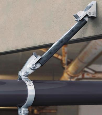
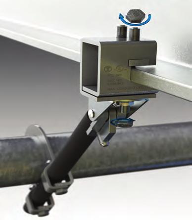
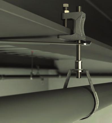
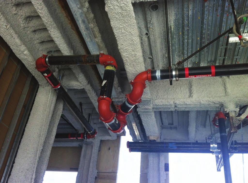
7 TOLBrace TOLBrace Fire Protection Software llows you to create a submittal sheet, with all relevant information, at the click of a mouse! TOLBrace 7.0 includes a feature that will automatically update your software, via the internet, when new products are added; when there are updates to codes and standards, and any necessary software upgrades. pplication Photos TOLBrace software assists a Fire Sprinkler system designer with the following: Seismic force factor calculations (Fp) Zone of influence calculations Sway brace orientation and angle selection Structural attachment of sway braces Brace material selection ppropriate selection of UL Listed and FM pproved sway brace components Creating a submittal sheet with all relevant information with the click of a mouse! TOLBrace follows the requirements of: NFP 13, 1999, 2002, 2007 & 2010 Uniform Building Code International Building Code National Building Code of Canada California Office of Statewide Health Planning & Development (OSHPD) Seismic Bracing Services & Products for Mechanical, Electrical and Plumbing Systems In addition to our long reputation as a provider of sway bracing products and software for the Fire Sprinkler Industry, we also provides a line of products and services directed to the installers of all other non-structural building systems. We provide: Pre-project bid assistance to contractors ssist building owner, architect and design engineer with code compliance and design questions Review and updates to product specifications Pre-pproved (OSHPD) and/or Project Specific Engineered Seismic Restraint Details Layout of Seismic Restraints on Project Drawings Product in "kit" or "bulk" shipments to meet all project management and budget requirements Installer training Post installation jobsite inspection For more information, visit 3


 Reversible")

 Fig.")


8 Pictorial Index Beam Clamps Pictorial Index B3037 Z-Purlin Beam Clamp Page 10 Fig. 66 Reversible Steel C-Clamp With Locknut 1 1 /4 Throat Page 14 Pipe Hangers B3033 Wide Jaw Top Flange C-Clamp Page 10 Fig. 67SS ( 3 /4 Throat) Fig. 68SS (1 1 /4 Throat) Reversible Stainless Steel C-Clamp With Locknut Page 15 B3034 Top Flange C-Clamp Page 11 Fig. 69 Retaining Strap Page 16 Fig. 68S ( 3 /4 Throat) Fig. 68W (1 1 /4 Throat) Malleable, Reversible Beam Clamps Page 12 Fig. 69R Retrofit Capable Retaining Strap Page 17 Fig. 65XT- 3 /8 Reversible Steel C-Clamp With Locknut 3 /4 Throat Page 13 B3042 (TOLCO 61T) Bar Joist Hanger Page 18 Fig. 65 Reversible Steel C-Clamp With Locknut 3 /4 Throat Page 13 Fig. 130 Composite Wood Joist Clamp Page 19 Fig. 1NFP NFP Clevis Hanger Page 20 Fig. 2 djustable Band Hanger Page 22 Figure 120 U Hanger Page 26 Fig. 2F Felt Lined djustable Band Hanger Page 22 Fig. 200 Trimline djustable Band Hanger Page 21 Fig. 200M Band Hanger Metric Rod Sizes Page 23 Fig. 200F Felt Lined Trimline djustable Band Hanger Page 21 Fig. 200C Plastic Coated Trimline djustable Band Hanger Page 21 B3198H (TOLCO 302) Hinged Extension Split Pipe Clamp Page 25 Fig. 200 H Heavy Duty Trapeze Band Hanger Page 24 Fig. 120MJ Mutt & Jeff U Hanger Page 27 Fig. 120W Wrap round U Hanger Page 27 Fig. 120RW Retrofit Wrap round U Hanger Clamp Page 28 B3198HCT (TOLCO 301CT) Copper Tubing Hinged Extension Split Pipe Clamp Page 25 u u DUR-COPPER Finish 4
 Standard Riser Clamp Page 29 B3373C")
 Two-Bolt")

 Plastic Coated")

 Washer Page 31 B2400")


 Base")
 Threaded Base Stand")
9 Pictorial Index Pipe Clamps B3373 (TOLCO 6) Standard Riser Clamp Page 29 B3373C (TOLCO 6PVC) Plastic Coated Standard Riser Clamp Page 29 B3132 (TOLCO 9) Two-Bolt Underground Clamp Page 30 B3134 (TOLCO 14) Four-Bolt Underground Clamp Page 31 B3140 (TOLCO 4) Standard Pipe Clamp Page 32 B3140C (TOLCO 4PVC) Plastic Coated Standard Pipe Clamp Page 32 Fig. 4B Pipe Clamp For Sway Bracing Page 33 B3132W (TOLCO 9X) Lug Washer Page 30 B3134W (TOLCO 14X) Washer Page 31 B2400 (TOLCO 2STR) Standard Pipe Strap Page 34 Pictorial Index Fig. 22 Single Fastener CPVC Strap Page 35 Fig. 22L2 One Hole Hanger/Restrainer for CPVC & Steel Pipe Page 36 Fig. 23 Double Fastener CPVC Strap Page 37 Fig. 24 Double Fastener Side Mounted CPVC Strap Page 38 Fig. 25 Surge Restrainer Page 38 Fig. 27B Speed Nut Page 39 Pipe Supports Fig. 28 Stand-Off Hanger & Restrainer for CPVC & IPS Pipe Page 40 Fig. 28M Offset Hanger & Restrainer for CPVC & IPS Pipe Page 41 Fig. 29 Double Offset Hanger & Restrainer for CPVC Pipe Page 42 Fig. B3184 Light Duty Offset Hanger for CPVC & IPS Pipe Page 43 B3088 (TOLCO 316) Base Stand B3088S Seismic Base Stand Pages 44 & 45 B3088T (TOLCO 316T) Threaded Base Stand B3088ST Seismic Threaded Base Stand Pages 44 & 45 B3092 (TOLCO 318) djustable Pipe Saddle Support With Yoke Page 46 B3093 (TOLCO 317) djustable Pipe Saddle Support Page 47 5


10 Pictorial Index Seismic Bracing Fig. 75 Swivel ttachment Page 48 Fig. 98B Rod Stiffener with Break Off Bolt Head Page 48 Fig. 4 Pipe Clamp For Sway Bracing Page 49 Fig. 4L Longitudinal In- Line Sway Brace ttachment Pages 50 & 51 Fig. 4L Longitudinal In- Line Sway Brace ttachment Pages 52 & 53 Fig. 800 djustable Sway Brace ttachment To Steel Pages 54 & 55 Pictorial Index Fig. 825 Sway Brace ttachment to Steel Pages 56 & 57 Fig. 828 Universal Sway Brace ttachment to Steel Pages 58 & 59 Fig. 825 Sway Brace ttachment to Steel Page 60 Fig. 906 Sway Brace Multi-Fastener dapter Page 61 Fig. 907 Multi-ngle ttachment Page 62 Fig. 909 No-Thread Swivel Sway Brace ttachment Page 63 Fig. 910 Threaded Swivel Sway Brace ttachment Page 64 Fig. 975 Straight Sway Brace Fitting Page 65 Fig. 980 Universal Swivel Sway Brace ttachment Pages 66 & 67 Fig Fast Clamp Sway Brace ttachment Pages 68 & 69 Fig Sway Brace ttachment Pages 70 & 71 Fig Sway Brace ttachment Page 72 Concrete Inserts Fig. 109 Concrete Deck Insert Pages 74 & 75 Fig. 109F Concrete Insert Pages 76 & 77 B2500 (TOLCO 310) Light Duty Spot Insert Page 78 N2500 (TOLCO 310N) Steel Insert Nut Page 78 B3014 (TOLCO 309) Malleable Iron Spot Insert Page 79 B3014N (TOLCO 309N) Malleable Iron Insert Nut Page 79 6
 Light Duty Welded Bracket Page 80")
")
 O Bracket Page 82 Upper")


 ngle Bracket Page 84")

 Rod ttachment Concrete Plate")


 Weldless Eye")
")
11 Pictorial Index Brackets B3065 (TOLCO 30L) Light Duty Welded Bracket Page 80 B3066 (TOLCO 30M) Medium Duty Welded Bracket Page 81 B3069W (TOLCO 31-M) Welded Knee Brace Page 82 B3069E (TOLCO 31-O) O Bracket Page 82 Upper ttachments Pictorial Index Fig. 78 ll Steel Ceiling Plate Page 83 Fig. 51 Side Beam Bracket For NFP Rod Page 83 Fig. 50 Side Beam Bracket For NFP Rod & Fastener Sizing Page 84 Fig. 56 Tapped Side Beam Connector Page 84 B3061 (TOLCO 42) ngle Bracket Page 84 Fig. 58 Threaded Side Beam Bracket Page 85 Fig. 75 Swivel ttachment Page 86 B3085 (TOLCO 35) Rod ttachment Concrete Plate Page 88 B3084 (TOLCO 33) Single Lug Concrete Plate Page 89 B3083 (TOLCO 305) B3083WO (TOLCO 304) Welded Beam ttachment Page 87 Threaded ccessories B3205 (TOLCO 103) Machine Threaded Rod Page 94 B3200 (TOLCO 330) Weldless Eye Nut Page 90 B501 (TOLCO 111) Light Weight U-Bolt Page 91 B3188 (TOLCO 110) Standard U-Bolt Pages 92 & 93 B3188C Plastic Coated Standard U-Bolt Pages 92 & 93 TR (TOLCO 99 & 100) ll Threaded Rod Page 94 7

 Linked Eye Rod Page")
 Coach Screw Rod Page 96 B3210")
 Welded Eye Rod Page 97 B655 (TOLCO 70) Steel Rod")
 J-Bolt Page 99")
 #16 x 2\" Drive Screw Page 99 B3220 (TOLCO")
 Square Washer Page 101 B3248 (TOLCO 118) Steel")
 Hex Nut HHN (TOLCO 114) Heavy")
 Lock Washer Page 103 FFW (TOLCO 119) Flat")
12 Pictorial Index Threaded ccessories Pictorial Index Fig. 98B Rod Stiffener with Break Off Bolt Head Page 95 Fig. 98 Rod Stiffener Page 95 B3214 (TOLCO 106) Tie Bolt Page 96 B3210X B3210XL (TOLCO 102L) Linked Eye Rod Page 98 B3211X B3211XL (TOLCO 101L) Linked Welded Eye Rod Page 98 B3213 (TOLCO 105) Coach Screw Rod Page 96 B3210 B3210L (TOLCO 102) Eye Rod Page 97 B3211 B3211L (TOLCO 101) Welded Eye Rod Page 97 B655 (TOLCO 70) Steel Rod Coupling Page 100 B656 (TOLCO 70R) Steel Reducer Rod Coupling Page 100 B3212 (TOLCO 104) J-Bolt Page 99 B3228 (TOLCO 126) Hex Head Lag Bolt Page 99 DS 16 x 2 (TOLCO 125) #16 x 2" Drive Screw Page 99 B3220 (TOLCO 71) Malleable Iron Rod Coupling Page 100 B200 (TOLCO F13-F17) Square Washer Page 101 B3248 (TOLCO 118) Steel Washer Plate Page 101 B3234 (TOLCO 116) Bevel Washer Page 101 HN (TOLCO 113) Hex Nut HHN (TOLCO 114) Heavy Hex Nut Page 102 FW (TOLCO 115) Flat Washer Page 103 LW (TOLCO 117) Lock Washer Page 103 FFW (TOLCO 119) Flat Fender Washer Page 103 8

 Fig.")
 Copper")


")
 Extended Leg Pipe")


 Pipe")
 Pipe Saddle With Strap")
")
 djustable Pipe")
 Light Duty Welded Bracket")
 Heavy Duty")

")


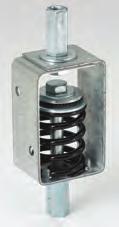
13 Pictorial Index Other Products (Refer to Pipe Hanger Catalog at for more information) Fig. 1CBS Clevis Pipe Spacer B3170CT (TOLCO 202) Copper Tubing djustable Swivel Ring B3170CTC Copper Tubing Plastic Coated djustable Swivel Ring B3198R Extension Split Pipe Clamp B3198RCT Copper Tubing Extension Split Pipe Clamp B3262 Light Duty Spring Hanger Pictorial Index B3148 (TOLCO 7) Offset Pipe Clamp B3180FL (TOLCO 20S) Flush Mount Pipe Strap B3180 (TOLCO 20) Extended Leg Pipe Strap B3096 (TOLCO 312) djustable Pipe Saddle Support B3089 (TOLCO 319) Pipe Support djuster B3090 (TOLCO 318) Pipe Saddle Support With U-Bolt B3095 (TOLCO 317) Pipe Saddle Support B3097 (TOLCO 311) Pipe Saddle With Strap B3195 (TOLCO 84) I.P.S. Isolator B3195CT (TOLCO 83) Copper Tubing Isolator B3098 (TOLCO 313) djustable Pipe Support w/u-bolt B3068 (TOLCO 30) Light Duty Welded Bracket B3064 djustable Strut Bracket B3067 (TOLCO 30H) Heavy Duty Welded Bracket Fig. 981 Fast-ttach Universal Swivel Sway Brace ttachment (For bracing of CPVC pipe) B3082 (TOLCO 337) Single Lug Concrete Plate B3086 (TOLCO 34) Clevis Concrete Plate TB (TOLCO 123) Toggle Bolt W (TOLCO 209) Wedge nchor B3203 (TOLCO 333) Extension Piece B3223 Offset Eye Socket SHE Isolation Spring Hanger RH Neoprene Hanger HSL/HS Vibration Spring Hanger HESL/HES Combination Spring & Neoprene 9
 for up to 4 (100mm) pipe.")
 Design Load: 400 Lbs. (1.78kN) Setscrew Torque: Per MSS SP-58 14.2.")
 Bottom Hanger Rod Threads 3/8\"-16 B3033 - Wide Jaw Reversible C-Clamp (TOLCO Fig.")
14 Beam Clamps B Z-Purlin Malleable C-Clamp Material: Malleable Iron Function: Designed for attaching a 3 /8"-16 hanger rod to the bottom flange of a Z-purlin. pprovals: Underwriters Laboratories Listed (culus) for up to 4 (100mm) pipe. Conforms to Federal Specification WW-H-171E & , Type 23 and Manufacturers Standardization Society NSI/MSS SP-69 & SP-58, Type 23. Finish: Plain or Electro-Galvanized Order By: Figure number and finish. Weight: pprox. Wt./ Lbs. (40.8kg) Design Load: 400 Lbs. (1.78kN) Setscrew Torque: Per MSS SP /8-16 set screws = 5 ft./lbs. (7 Nm) Caution should be taken not to over-tighten set screws. Set Screw and Locknut Included 3" (76.2) Throat Opening 31/32" (24.6) 3 13 /32" (86.5) Bottom Hanger Rod Threads 3/8"-16 B Wide Jaw Reversible C-Clamp (TOLCO Fig. 68) Size Range: 3 /8"-16 thru 3 /4"-10 rod Material: Cast Malleable Steel with hardened cup point set screw and jam nut Function: For attachment to structural shapes requiring wider throat especially under roof with bar joist construction. This clamp may be used with the set screw in the up or down position. pprovals: Underwriters Laboratories Listed (culus) and Factory Mutual Engineering pproved (FM) for 3 /8-16 and 1 /2-13 rod sizes. Conforms to Federal Specification WW-H-171E Type 19 & , Type 19 & 23 and Manufacturers Standardization Society NSI/MSS SP-69 & SP-58, Type 19 & 23. Factory Mutual Engineering pproved only with the setscrew in the down position. Finish: Plain. Contact B-Line for alternative finishes and materials. Order By: Figure number, rod size and finish Setscrew Torque: Per MSS SP /8-16 set screws = 5 ft./lbs. (7 Nm) 1 /2-13 set screws = 11 ft./lbs. (15 Nm) 5 /8-11 set screws = 21 ft./lbs. (28 Nm) Caution should be taken not to over-tighten set screws. Designed to meet or exceed requirements of FM DS 2-0. Beam Clamps Throat Opening 1 1 /4" (31.7) for B /8 & 1 /2 1 5 /16" (33.3) for B /8 & 3 /4 C Set Screw and Locknut Included D B (Rod Size) Hanger Rod Not Included Top Flange ttachment pplications Bottom Flange ttachment pplications Part Rod Set Screw Maximum Iron pprox. No. Size Size B C D Pipe Size Per UL Wt./100 in. (mm) in. (mm) in. (mm) in. (mm) Lbs. (kg) B /8 3 /8"-16 3 /8"-16 x /4" (57.1) 2" (50.8) 1 1 /8" (28.6) 4" (100) 54 (24.5) B /2 1 /2"-13 1 /2"-13 x 2 1 /2 2 5 /16" (58.7) 2 3 /16" (55.6) 1 1 /4" (31.7) 8" (200) 51 (23.1) B /8 5 /8"-11 1 /2"-13 x 2 1 /2 2 5 /8" (66.7) 2 1 /2" (63.5) 1 3 /8" (34.9) 8" (200) 70 (31.7) B /4 3 /4"-10 5 /8"-11 x 2 1 / /16" (68.3) 2 1 /2" (63.5) 1 7 /16" (36.5) 10" (250) 98 (44.4) 10
. Features: May be used on top or bottom flange of the beam. Beveled lip allows hanging from top flange where clearance is limited.")
 and Factory Mutual Engineering pproved (FM) for 3 /8-16 and 1 /2-13 rod sizes.")
 Listed to support up to 4\" (100mm) pipe with the set screw in the down position, up to 3\" (75mm) pipe with the set screw in the up position.")

15 Beam Clamps B C-Clamp Size Range: 3 /8"-16 thru 3 /4"-10 rod Material: Cast Malleable Steel with hardened cup point set screw and jam nut Function: Recommended for hanging from steel beam where flange thickness does not exceed 3 /4" (19.0mm). Features: May be used on top or bottom flange of the beam. Beveled lip allows hanging from top flange where clearance is limited. May be installed with the set screw in the up or down position. Offset design permits unlimited rod adjustment by allowing the rod to be threaded completely through the clamp. The rear window design permits inspection of thread engagement. pprovals: Underwriters Laboratories Listed (culus) and Factory Mutual Engineering pproved (FM) for 3 /8-16 and 1 /2-13 rod sizes. Conforms to Federal Specification WW-H-171E & , Type 23 and Manufacturers Standardization Society NSI/MSS SP-69 & SP-58, Type /8"-16 is (culus) Listed to support up to 4" (100mm) pipe with the set screw in the down position, up to 3" (75mm) pipe with the set screw in the up position. 1 /2"-13 is (culus) Listed to support up to 8" (200mm) pipe with the set screw in the down position, up to 6" (150mm) pipe with the set screw in the up position. Factory Mutual Engineering pproved only with the setscrew in the down position. Finish: Plain. Contact B-Line for alternative finishes and materials. Order By: Figure number, rod size and finish Setscrew Torque: Per MSS SP /8-16 set screws = 5 ft./lbs. (7 Nm) 1 /2-13 set screws = 11 ft./lbs. (15 Nm) Caution should be taken not to over-tighten set screws. Throat Opening 3/4" (19.0) C Set Screw and Locknut Included Top Flange ttachment pplications B D (Rod Size) Hanger Rod Not Included Beam Clamps B /8" and B /4" sizes ttach only as shown. C D Throat Opening 3/4" (19.0) Set Screw and Locknut Included B (Rod Size) Hanger Rod Not Included Bottom Flange ttachment pplications Part Rod Set Screw Maximum Iron pprox. No. Size Size B C D Pipe Size Per UL Wt./100 in. (mm) in. (mm) in. (mm) in. (mm) Lbs. (kg) B /8 3 /8"-16 3 /8"-16 x 1 1 /2 1 5 /8" (41.3) 2" (50.8) 7 /8" (19.0) 4" (100) 30 (13.6) B /2 1 /2"-13 1 /2"-13 x 1 1 / /16" (46.0) 2 3 /16" (55.6) 1 3 /16" (30.2) 8" (200) 47 (21.3) B /8 5 /8"-11 1 /2"-13 x /4" (44.5) 2 1 /8" (54.0) 1 1 /4" (31.7) (26.3) B /4 3 /4"-10 1 /2"-13 x 2 2" (50.8) 2 1 /4" (57.2) 1 1 /4" (31.7) (35.0) 11
 Throat Opening (bottom of page) Beam Clamps Size Range: 3 /8\"-16 rod sizes thru 7 /8\"-9 rod sizes Material: Cast Malleable Steel with hardened cup point set screw and jam nut Function:")

16 Beam Clamps Fig. 68S - Reversible Malleable Beam Clamp 3 /4 (19.0mm) Throat Opening Fig. 68W - Reversible Malleable Beam Clamp 1 1 /4 (31.7mm) Throat Opening (bottom of page) Beam Clamps Size Range: 3 /8"-16 rod sizes thru 7 /8"-9 rod sizes Material: Cast Malleable Steel with hardened cup point set screw and jam nut Function: Recommended for hanging from steel beam where flange thickness does not exceed 3 /4 (19.0mm) on Fig. 68S or 1 1 /4 (31.7mm) on Fig.68W. Features: May be used on top or bottom flange of beam. Beveled lip allows hanging from top flange where clearance is limited. May be installed with set screw in up or down position. Offset design permits unlimited rod adjustment by allowing the rod to be threaded completely through the clamp. The rear window design permits inspection of thread engagement. F pprovals: Factory Mutual Engineering pproved. Underwriters Laboratories Listed. Conforms to Federal Specification WW-H-171E, Type 23 and Manufacturers Standardization Society SP-58, Type 19. Fig. 68S- 3 /8 is culus Listed to support up to 4 (100mm) pipe with the set screw (Rod Size) in the down position and up to 3 (80mm) pipe with the set screw in the up position. Hanger Rod Fig. 68S- 1 Not Included /2 is culus Listed to support up to 8 (200mm) pipe with the set screw in the down position and up to 6 (150mm) pipe with the set screw in the up position. Fig. 68S Fig. 68W- 3 /8 is culus Listed to support up to 4 (100mm) pipe with the set screw in the down position and up to 4 (100mm) pipe with the set screw in the up position. Fig. 68W- 1 D = Depth of Throat /2 is culus Listed to support up to 6 (150mm) pipe with the set screw in the down position and up to 6 (150mm) pipe with the set screw in the up position. Factory Mutual Engineering pproved (FM) only with the set screw in the down position. (OSHPD). For additional load spacing and placement information relating OSHPD projects, please refer to the Seismic Restraint System Guidelines. F Finish: Plain. Contact B-Line for Electro-Galvanized or HDG finishes. Order By: Part number and finish Setscrew Torque: Per MSS SP /8-16 set screws = 5 ft./lbs. (7 Nm) 1 /2-13 set screws = 11 ft./lbs. (15 Nm) 5 /8-11 set screws = 21 ft./lbs. (28 Nm) Caution should be taken not to over-tighten set screws. Fig. 68S Fig. 68W (Rod Size) Hanger Rod Not Included Fig. 68W B B Set Screw and Locknut Included D D E C E C Fig. 68S Set Screw and Locknut Included C Max Rec. Load Max Rec. Load pprox. Part Rod Size B Min. D E F Set Screw Up Set Screw Down Wt./100 No. in. (mm) in. (mm) in. (mm) in. (mm) in. (mm) Lbs. (kn) Lbs. (kn) Lbs. (kg) 68S- 3 /8 3 / /16 (39.7) 3 /4 (19.0) 1 1 /8 (28.6) 7 /16 (11.1) 7 /8 (22.2) 610 (2.71) 610 (2.71) 32 (14.5) 68S- 1 /2 1 / /8 (41.3) 3 /4 (19.0) 1 (25.4) 7 /16 (11.1) 1 1 /8 (28.6) 750 (3.33) 1130 (5.02) 54 (24.5) 68S- 5 /8 5 / /16 (39.7) 3 /4 (19.0) 1 (25.4) 9 /16 (14.3) 1 1 /8 (28.6) 750 (3.33) 1130 (5.02) 50 (22.7) 68S- 3 /4 3 / /4 (44.4) 3 /4 (19.0) 1 1 /8 (28.6) 9 /16 (14.3) 1 1 /4 (31.7) 750 (3.33) 1130 (5.02) 81 (36.7) 68S- 7 /8 7 / /4 (44.4) 3 /4 (19.0) 1 1 /8 (28.6) 9 /16 (14.3) 1 5 /16 (33.3) 750 (3.33) 1130 (5.02) 75 (34.0) Fig. 68W C Max Rec. Load Max Rec. Load pprox. Part Rod Size B Min. D E F Set Screw Up Set Screw Down Wt./100 No. in. (mm) in. (mm) in. (mm) in. (mm) in. (mm) Lbs. (kn) Lbs. (kn) Lbs. (kg) 68W- 3 /8 3 / /16 (39.7) 1 1 /4 (31.7) 1 1 /8 (28.6) 7 /16 (11.1) 7 /8 (22.2) 610 (2.71) 610 (2.71) 41 (18.6) 68W- 1 /2 1 / /16 (39.7) 1 1 /4 (31.7) 1 (25.4) 5 /8 (15.9) 1 1 /8 (28.6) 750 (3.33) 1130 (5.02) 66 (29.9) 68W- 5 /8 5 / /2 (38.1) 1 1 /4 (31.7) 1 (25.4) 9 /16 (14.3) 1 1 /8 (28.6) 750 (3.33) 1130 (5.02) 68 (30.8) 68W- 3 /4 3 / /4 (44.4) 1 1 /4 (31.7) 1 1 /8 (28.6) 3 /8 (19.5) 1 1 /4 (31.7) 750 (3.33) 1130 (5.02) 110 (49.9) 68W- 7 /8 7 / /4 (44.4) 1 1 /4 (31.7) 1 1 /8 (28.6) 9 /16 (14.3) 1 5 /16 (33.3) 750 (3.33) 1130 (5.02) 98 (44.4) 12

. Features: ll steel construction eliminates structural deficiencies associated with casting type beam clamps. May be used on top or bottom flange of beam.")

17 Fig Reversible Steel C-Type Beam Clamp 3 /4 (19.0mm) Throat Opening Fig. 65XT - Reversible Steel C-Type Beam Clamp 3 /4 (19.0mm) Throat Opening (bottom of page) Beam Clamps Size Range: Fig /2"-13 rod sizes, and 5 /8"-11 rod sizes Fig. 65XT - 3 /8"-16 rod size (see below) Material: Steel with hardened cup point set screw and jam nut Function: Recommended for hanging from steel beam where flange thickness does not exceed 3 /4 (19.0mm). Features: ll steel construction eliminates structural deficiencies associated with casting type beam clamps. May be used on top or bottom flange of beam. (Beveled lip allows hanging from top flange where clearance is limited.) May be installed with set screw in up or down position. Offset design permits unlimited rod adjustment by allowing the rod to be threaded completely through the clamp. Open design permits inspection of thread engagement. pprovals: Underwriters Laboratories Listed in the US (UL) and Canada (cul). Exceeds requirements of the National Fire Protection ssociation (NFP), pamphlet 13, 3 /8"-16 rod will support 1 /2 (15mm) thru 4 (100mm) pipe 1 /2"-13 rod will support thru 8 (200mm) pipe Finish: Plain. Contact B-Line for alternative finishes and materials. Order By: Figure number and finish Fig. 65 Patent #4,570,885 F Set Screw and Locknut Included B D E C Part Rod Size B C D E No. in. (mm) in. (mm) in. (mm) in. (mm) Beam Clamps 65-1 /2 1 / /2 (38.1) 3 /4 (19.0) 1 (25.4) 9 /16 (14.3) 65-5 /8 5 / /2 (38.1) 3 /4 (19.0) 1 (25.4) 9 /16 (14.3) Part F pprox. Wt./100 No. in. (mm) Lbs. (kg) 65-1 /2 1 1 /4 (31.7) 55 (24.9) 65-5 /8 1 1 /4 (31.7) 55 (24.9) Fig. 65XT- 3 /8 - Beam Clamp Feature: Extruded holes allows for more thread engagement of threaded rod and set screw. Weight: pprox. Wt./ Lbs. (12.7kg) Finish: Plain or Electro-Galvanized Order By: Figure number and finish pprovals: Underwriters Laboratories Listed (culus) and FM pproved (FM) for up to 4 (100mm) pipe. Designed to meet or exceed requirements of FM DS /4" (19.0) Set Screw and Locknut Included 1 3 /8" (34.9) 1" (25.4) 1 9 /16" (39.7) 7/8" (22.2) 13
 Throat Opening Size Range: 3 /8\"-16, 1 /2\"-13 rod sizes, and 5 /8\"-11 rod sizes Material: Steel with hardened cup point set screw and jam nut Function: Recommended for hanging from steel beam")
18 Beam Clamps Fig Reversible Steel C-Type Beam Clamp 1 1 /4 (31.7mm) Throat Opening Size Range: 3 /8"-16, 1 /2"-13 rod sizes, and 5 /8"-11 rod sizes Material: Steel with hardened cup point set screw and jam nut Function: Recommended for hanging from steel beam where flange thickness does not exceed 1 1 /4 (31.7mm). Features: ll steel construction eliminates structural deficiencies associated with casting type beam clamps. May be used on top or bottom flange of beam. (Beveled lip allows hanging from top flange where clearance is limited.) May be installed with set screw in up or down position. Offset design permits unlimited rod adjustment by allowing the rod to be threaded completely through the clamp. Open design permits inspection of thread engagement. pprovals: Underwriters Laboratories Listed in the US (UL) and Canada (cul). Exceeds requirements of the National Fire Protection ssociation (NFP), pamphlet 13, 3 /8"-16 rod will support 1 /2 (15mm) thru 4 (100mm) pipe 1 /2"-13 rod will support thru 8 (200mm) pipe Finish: Plain. Contact B-Line for alternative finishes and materials. Order By: Figure number and finish F B D E C Beam Clamps Set Screw and Locknut Included Part Rod Size B C D E No. in. (mm) in. (mm) in. (mm) in. (mm) 66-3 /8 3 / /16 (30.2) 1 1 /4 (31.7) 1 (25.4) 7 /16 (11.1) 66-1 /2 1 / /2 (38.1) 1 1 /4 (31.7) 1 (25.4) 9 /16 (14.3) 66-5 /8 5 / /2 (38.1) 1 1 /4 (31.7) 1 (25.4) 9 /16 (14.3) Part F pprox. Wt./100 No. in. (mm) Lbs. (kg) 66-3 /8 1 (25.4) 28 (12.7) 66-1 /2 1 1 /4 (31.7) 55 (24.9) 66-5 /8 1 1 /4 (31.7) 55 (24.9) 14
 Function: Recommended for hanging from steel")

19 Beam Clamps Fig. 67SS - Stainless Steel Reversible C-Type Beam Clamp 3 /4 (19.0mm) Throat Opening Fig. 68SS - Stainless Steel Reversible C-Type Beam Clamp Wide Mouth Size Range: 3 /8"-16 and 1 /2"-13 rod sizes Material: Stainless Steel (Type 316 or 304) Function: Recommended for hanging from steel beams where flange thickness does not exceed 3 /4 (19.0mm) for Fig. 67SS or 1 1 /4 (31.7mm) for Fig. 68SS. Features: ll steel construction eliminates structural deficiencies associated with casting type beam clamps. May be used on top or bottom flange of beam. May be installed with set screw in up or down position. Offset design permits unlimited rod adjustment by allowing the rod to be threaded completely through the clamp. pprovals: Underwriters Laboratories Listed in the US (UL) and Canada (cul). Conforms to Manufacturers Standardization Society NSI/MSS SP-69 & SP-58, Type 19. Meets or exceeds requirements of the National Fire Protection ssociation (NFP), pamphlet /8"-16 rod will support 1 /2 (15mm) thru 4 (100mm) pipe 1 /2"-13 rod will support thru 8 (200mm) pipe B E G Order By: Figure number and stainless steel type. D C F Fig. 67SS Set Screw and Locknut Included Beam Clamps Part Rod Size Pipe Size B C D E No. in. (mm) in. (mm) in. (mm) in. (mm) in. (mm) 67SS- 3 /8 3 / /2" - 4 (15-100) 3 (76,2) 7 /8 (22.2) 1 (25.4) 1 5 /8 (41.3) 67SS- 1 /2 1 /2-13 5" - 8 ( ) 3 (76,2) 7 /8 (22.2) 1 (25.4) 1 5 /8 (41.3) Part F G pprox. Wt./100 No. in. (mm) in. (mm) Lbs. (kg) 67SS- 3 /8 1 5 /8 (41.3) 1 1 /8 (28.6) 84 (38.1) 67SS- 1 /2 1 5 /8 (41.3) 1 1 /8 (28.6) 170 (77.1) Fig. 68SS Part Rod Size Pipe Size B C D E No. in. (mm) in. (mm) in. (mm) in. (mm) in. (mm) 68SS- 3 /8 3 / /2" - 4 (15-100) 2 1 /16 (52.4) 1 1 /8 (28.6) 3 /4 (19.0) 1 1 /4 (31.7) 68SS- 1 /2 1 /2-13 5" - 8 ( ) 2 1 /4 (57.1) 1 1 /4 (31.7) 13 /16 (20.6) 1 1 /4 (31.7) Part F pprox. Wt./100 No. in. (mm) Lbs. (kg) 68SS- 3 /8 2 (50.8) 84 (38.1) 68SS- 1 /2 2 1 /4 (57.1) 170 (77.1) 15
20 Beam Clamps Fig Beam Clamp Retaining Strap (B-Line B3367) Beam Clamps Size Range: 3 /8"-16 thru 3 /4"-10 rod 4 (101.6mm) thru 16 (406.4mm) lengths Note: longer lengths are available consult factory Material: Pre-Galvanized Steel Function: To offer more secure fastening of various types of beam clamps to beam where danger of movement might be expected. NFP 13 requires the use of retaining straps with all beam clamps installed in earthquake areas. Satisfies requirements of NFP 13. Important Note: Good installation practice of a retaining strap requires that the strap be held tightly and securely to all component parts of the assembly. Therefore a locking mechanism of some kind, such as a hex nut for the Fig. 69 will provide a more secure reliable installation. pprovals: Underwriters Laboratories Listed in the US (UL) and Canada (cul). pproved for use with any listed beam clamp. Finish: Pre-Galvanized Order By: Figure number, length (L), and finish. Note: Minimum return on strap is 1 (25.4mm) For Use With: ny B-Line or TOLCO beam clamp. Hole Dia. D Length Part No. in. (mm) 69-3 /8-L 7 /16 (30.1) Specify 69-1 /2-L 9 /16 (30.1) Specify 69-5 /8-L 11 /16 (50.8) Specify 69-3 /4-L 13 /16 (63.5) Specify 16
 lengths Note: longer lengths are available consult factory Material: Pre-Galvanized Steel Function: To offer more secure fastening of various types of beam clamps to beam where danger of")
21 Beam Clamps Fig. 69R - Retrofit Capable Beam Clamp Retaining Strap Size Range: 3 /8"-16 & 1 /2"-13 rod 4 (101,6mm) thru 16 (406.4mm) lengths Note: longer lengths are available consult factory Material: Pre-Galvanized Steel Function: To offer more secure fastening of various types of beam clamps to beam where danger of movement might be expected. NFP 13 requires the use of retaining straps with all beam clamps installed in earthquake areas. Satisfies requirements of NFP 13. Features: Beveled locking slot* is precisely formed to align with the threaded section of a hanger rod or set screw and engage the unit securely. May be used as shown in Section - or inverted. llows easy installation for new construction or retrofit applications. Important Note: Good installation practice of a retaining strap requires that the strap be held tightly and securely to all component parts of the assembly. Therefore the beveled locking slot of the Fig. 69R will provide a secure reliable installation. pprovals: Underwriters Laboratories Listed in the US (UL) and Canada (cul). pproved for use with any listed beam clamp. Finish: Pre-Galvanized Order By: Figure number, length, and finish. Note: Minimum return on strap is 1 (25.4mm) For Use With: ny B-Line or TOLCO beam clamp. * Patent #5,947,424 Component of State of California OSHPD pproved Seismic Restraints System - Beam Clamps Slot Width Length Part No. in. (mm) 69R- 3 /8-L 7 /16 (30.1) Specify 69R- 1 /2-L 9 /16 (30.1) Specify 17
22 Beam Clamps B3042T - Bar Joist Hanger (TOLCO Fig. 61T) Size Range: 3 /8"-16 and 1 /2"-13 rod Material: Steel Function: Designed to hook on top chord of metal bar joist. Hanger rod is threaded into product and secured with a washer and nut. pprovals: Underwriters Laboratories Listed in the US (UL) and Canada (cul) for up to 4 (100mm) pipe with 3 /8"-16 rod, up to 6 (150mm) pipe with 1 /2"-13 rod. Finish: Plain. Contact B-Line for alternative finishes and materials. Order By: Figure number, rod size, width and thickness of bar joist, and finish. Beam Clamps Rod Size For Pipe Size pprox. Wt./100 Part No. Size in. (mm) Lbs. (kg) B3042T- 3 /8 3 /8"-16 Up to 4" (up to 100) 50.6 (22.9) B3042T- 1 /2 1 /2"-13 6" (150) 50.0 (22.7) 18
 Size Range: 130-1 = TJI 35 130-2 = 130-3 = TJI 25 130-4 = TJI 55 & 65 130-5 = TJI 75 130-6 = TJI 96 Material: Steel H W Function: Designed for attachment to composite wood joist beams.")
23 Beam Clamps Fig Composite Wood Joist Clamp (B-Line Fig. B3052) Size Range: = TJI = = TJI = TJI 55 & = TJI = TJI 96 Material: Steel H W Function: Designed for attachment to composite wood joist beams. Use with eye rods, eye sockets, or angle bracket. pprovals: Sizes 1-6 are Underwriters Laboratories Listed in the US (UL) and Canada (cul) list through 4 (100mm) pipe. ll Fig. 130 Beam Clamps meet requirements of Factory Mutual Engineering (FM) and NFP 13, through 4 (100mm) pipe. Finish: Electro-Galvanized or Hot-Dip Galvanized Order By: Figure number and finish. Hardware Included 1" (25.4) 1/8" (3.2) Material Thickness 11 Gauge (3.0) 2" (50.8) 3/8" (9.5) 3/4" (19.0) Designed to meet or exceed requirements of FM DS 2-0. Beam Clamps Part Hardware H W pprox. Wt./100 No. Size in. (mm) in. (mm) in. (mm) Lbs. (kg) / /4" (82.5) 1 1 /2" (38.1) 2 5 /16" (58.7) 65 (29.5) / /2" (88.9) 1 3 /4" (44.4) 2 1 /2" (63.5) 70 (31.7) / /4" (82.5) 1 1 /2" (38.1) 1 3 /4" (44.4) 58 (26.3) / /2" (88.9) 1 1 /2" (38.1) 3 1 /2" (88.9) 83 (37.6) / /8" (92.1) 1 3 /4" (44.4) 3 1 /2" (88.9) 86 (39.0) / /2" (114.3) 2 1 /2" (63.5) 3 7 /8" (98.4) 101 (45.8) H and W are beam dimensions. Larger bolts and I-rods are required for 5 (125mm) and 6 (150mm) pipe sizes 19
 thru 12 (300mm) Size Range: 3 /4 (20mm) to 12 (300mm) Material: Steel Function: Recommended for the suspension of non-insulated pipe or insulated pipe")
 must be installed. Order pipe sleeves Fig. 1CBS-(pipe size) separately.")
24 Pipe Hangers B Clevis Hanger for NFP Sizes 3 /4 (20mm) thru 2 (50mm) Fig. 1NFP - Clevis Hanger for NFP Sizes 2 1 /2 (65mm) thru 12 (300mm) Size Range: 3 /4 (20mm) to 12 (300mm) Material: Steel Function: Recommended for the suspension of non-insulated pipe or insulated pipe with a B3151 shield. Note: When an oversized clevis is used, a pipe spacer should be placed over the cross bolt to assure that the lower U-strap will not move in on the bolt. When attaching seismic bracing to the clevis hangers, a 1CBS (clevis bolt spacer) must be installed. Order pipe sleeves Fig. 1CBS-(pipe size) separately. pprovals: Underwriter's Laboratories Listed in the US (UL) and Canada (cul) for sizes 3 /4" (20) thru 12" (300). Factory Mutual Engineering pproved (FM) for 3 /4 (20mm) thru 8 (200mm) pipe. Conforms to Federal Specification WW-H-171E & , Type 1 and Manufacturers Standardization Society NSI/MSS SP-69 & SP-58, Type 1. Rod sizes per National Fire Protection ssociation (NFP) Pamphlet 13. Maximum Temperature: 650 F (343 C). Standard Finish: Plain, Electro-Galvanized, DUR-GREEN, or Hot-Dip Galvanized also available in Stainless Steel Order By: Figure number and finish. For pipe sizes under 2 1 /2 (65mm) order B3100 Clevis Hanger, see chart below. Designed to meet or exceed requirements of FM DS 2-0. (Rod Size) Hanger Rod Not Included B Overall Height. C Bottom of hanger rod nut to center of pipe. D Bottom of hanger rod nut to top clevis bolt. C D B Pipe Hangers Nominal Pipe Size Rod Size B C D pprox. Wt./100 Part No. in. (mm) in. (mm) in. (mm) in. (mm) Lbs. (kg) B /4 3 /4" (20) 3 /8" /8" (66.7) 1 9 /16" (39.7) 9 /16" (14.3) 29 (13.1) B " (25) 3 /8" /16" (68.3) 1 9 /16" (39.7) 11 /16" (17.5) 35 (15.9) B /4 1 1 /4" 32) 3 /8" /16" (81.0) 1 7 /8" (47.6) 15 /16" (29.8) 40 (18.1) B /2 1 1 /2" (40) 3 /8" /8" (85.7) 1 15 /16" (49.2) 1 1 /4" (31.7) 42 (19.0) B " (50) 3 /8" /16" (115.9) 2 7 /8" (73.0) 1 1 /8" (28.6) 52 (23.6) 1NFP-2 1 /2 2 1 /2" (65) 3 /8" /16" (134.9) 3 1 /4" (82.5) 1" (25.4) 124 (56.2) 1NFP-3 3" (80) 3 /8" /16" (150.8) 3 1 /2" (88.9) 1 1 /4" (31.7) 140 (63.5) 1NFP-3 1 /2 3 1 /2" (90) 3 /8" /16" (163.5) 3 3 /4" (95.2) 1 1 /4" (31.7) 152 (68.9) 1NFP-4 4" (100) 3 /8" /8" (187.3) 4 1 /4" (107.9) 1 1 /2" (38.1) 190 (86.2) 1NFP-5 5" (125) 1 /2" /16" (226.9) 5 1 /4" (133.3) 1 1 /2" (38.1) 235 (106.6) 1NFP-6 6" (150) 1 /2" /16" (249.2) 5 1 /2" (139.7) 1 1 /2" (38.1) 317 (143.8) 1NFP-8 8" (200) 1 /2" /16" (319.1) 7 1 /8" (181.0) 2" (50.8) 428 (194.1) 1NFP-10 10" (250) 5 /8" /4" (412.7) 9 5 /8" (244.5) 3 1 /4" (82.5) 918 (416.4) 1NFP-12 12" (300) 5 /8" /16" (471.5) /16" (268.3) 3 1 /8" (79.4) 1086 (492.6) Revised 8/8/
 Fig. 200S - Trimline djustable Band Hanger with Non-Captured Nut Pipe Hangers Size Range: Fig.")

 thru 8 (200mm)) Spring tension on nut holds it securely in hanger before installation.")
25 Fig Trimline djustable Band Hanger (B-Line Fig. B3170NF) Fig. 200F - Trimline djustable Band Hanger with Felt Lining (B-Line Fig. B3170NFF) Fig. 200C - Trimline djustable Band Hanger with Plastic Coated (B-Line Fig. B3170NFC) Fig. 200S - Trimline djustable Band Hanger with Non-Captured Nut Pipe Hangers Size Range: Fig /2 (15mm) thru 8 (200mm) pipe Material: Steel, Pre-Galvanized to G90 specifications Function: For fire sprinkler and other general piping purposes. Knurled swivel nut design permits hanger adjustment after installation. Features: ( 1 /2 (15mm) thru 2 (50mm)) Flared edges ease installation for all pipe types and protect CPVC plastic pipe from abrasion. Captured design keeps adjusting nut from separating with hanger. Hanger is easily installed around pipe. For hanger with non-captured nut order Fig. 200S. (2 1 /2 (65mm) thru 8 (200mm)) Spring tension on nut holds it securely in hanger before installation. djusting nut is easily removed. pprovals: Underwriters Laboratories listed ( 1 /2 (15mm) thru 8 (200mm)) in the US (UL) and Canada (cul) for steel and CPVC plastic pipe and Factory Mutual Engineering pproved (FM) ( 3 /4 (20mm) thru 8 (200mm)). Conforms to Federal Specifications WW-H-171E & , Type 10 and Manufacturers Standardization Society NSI/MSS SP-69 & SP-58, Type 10. Maximum Temperature: 650 F (343 C) Finish: Pre-Galvanized. Stainless Steel materials will be supplied with (2) hex nuts in place of a knurl nut. Order By: Figure number and pipe size B Fig / /4 Fig to Fig /2 to Designed to meet or exceed requirements of FM DS 2-0. Fig. 200 Pipe Hangers Fig. 200C Fig. 200F Pipe Size Rod Size B pprox. Wt./100 Part No. in. (mm) in. (mm) in. (mm) lbs. (kg) /2 1 /2" (15) 3 /8" /8" (79.4) 2 5 /8" (66.7) 11 (5.0) /4 3 /4" (20) 3 /8" /8" (79.4) 2 1 /2" (63.5) 11 (5.0) " (25) 3 /8" /8" (85.7) 2 5 /8" (66.7) 12 (5.5) /4 1 1 /4" (32) 3 /8" /4" (94.0) 2 7 /8" (73.0) 13 (5.9) /2 1 1 /2" (40) 3 /8" /8" (98.4) 2 7 /8" (73.0) 14 (6.4) " (50) 3 /8" /2" (114.3) 3" (76.3) 15 (6.9) /2 2 1 /2" (65) 3 /8" /8" (142.9) 4 1 /8" (104.7) 27 (12.3) " (75) 3 /8" /8" (149.1) 4" (101.6) 29 (13.3) /2 3 1 /2" (90) 3 /8" /8" (187.3) 5 1 /4" (133.3) 34 (15.6) " (100) 3 /8" /8" (187.3) 5" (127.0) 35 (16.0) " (125) 1 /2" /8" (231.8) 6 1 /4" (158.7) 66 (30.2) " (150) 1 /2" /8" (257.2) 6 3 /4" (171.4) 73 (33.4) " (200) 1 /2" /8" (333.4) 8 3 /4" (222.2) 136 (62.3) Fig. 200S 21
 thru 6 (150mm) pipe Material: Pre-Galvanized Steel Function: Recommended for the suspension of noninsulated pipe or insulated pipe with B3151 shield. Fig.")
26 Pipe Hangers Fig. 2 - djustable Band Hanger (B-Line B3170) Fig. 2F - djustable Band Hanger Felt Lined for Copper Tubing (B-Line B3170F) Size Range: Fig /2 (65mm) thru 6 (150mm) pipe Fig. 2F /2 (65mm) thru 6 (150mm) pipe Material: Pre-Galvanized Steel Function: Recommended for the suspension of noninsulated pipe or insulated pipe with B3151 shield. Fig. 2NFP accomodates the reduced rod schedule of the National Fire Pretection ssociation Pamphlet 13. pprovals: Factory Mutual Engineering pproved. Underwriters Laboratories Listed. Conforms to Federal Specification WW-H-171E & Type 10 and Manufacturers Standardization Society NSI/MSS SP-69 & SP-58, Type 10. Standard Finish: Pre-Galvanized Note: vailable in Stainless Steel material. Order By: Part number and finish. B C D Fig. 2 C B Fig. 2F D Pipe Hangers Fig. 2 Nominal Pipe Size Rod Size B C D Max. Rec. Load pprox Wt./100 Part No. in. (mm) in. (mm) in. (mm) in. (mm) lbs. (kn) lbs. (kg) /2 2 1 /2" (65) 1 /2"-13 * 5 3 /4" (146.0) 4 1 /4" (107.9) 1 5 /8" (41.3) 600 (2.67) 41 (18.6) 2-3 3" (75) 1 /2"-13 * 6" (152.4) 4 1 /8" (104.8) 1 1 /4" (31.7) 600 (2.67) 45 (20.4) /2 3 1 /2" (90) 1 /2"-13 * 7 3 /8" (187.3) 5 1 /4" (133.3) 2 1 /8" (54.0) 600 (2.67) 52 (23.6) 2-4 4" (100) 5 /8"-11 * 7 3 /8" (187.3) 5" (127.0) 1 5 /8" (41.3) 1000 (4.45) 59 (27.6) 2-5 5" (125) 5 /8"-11 ** 9" (228.6) 6 1 /8" (155.6) 2 1 /4" (57.1) 1250 (5.56) 97 (44.0) 2-6 6" (150) 3 /4"-10 ** 9 3 /8" (238.1) 6 1 /2" (165.1) 1 7 /8" (47.6) 1250 (5.56) 139 (63.0) Fig. 2F Nominal Pipe Size Rod Size B C D Max. Rec. Load pprox Wt./100 Part No. in. (mm) in. (mm) in. (mm) in. (mm) lbs. (kn) lbs. (kg) 2F-2 1 /2 2 1 /2" (65) 1 /2"-13 * 5 3 /4" (146.0) 4 1 /4" (107.9) 1 5 /8" (41.3) 600 (2.67) 41 (18.6) 2F-3 3" (75) 1 /2"-13 * 6" (152.4) 4 1 /8" (104.8) 1 1 /4" (31.7) 600 (2.67) 45 (20.4) 2F-3 1 /2 3 1 /2" (90) 1 /2"-13 * 7 3 /8" (187.3) 5 1 /4" (133.3) 2 1 /8" (54.0) 600 (2.67) 52 (23.6) 2F-4 4" (100) 5 /8"-11 * 7 3 /8" (187.3) 5" (127.0) 1 5 /8" (41.3) 1000 (4.45) 59 (27.6) 2F-5 5" (125) 5 /8"-11 ** 9" (228.6) 6 1 /8" (155.6) 2 1 /4" (57.1) 1250 (5.56) 97 (44.0) 2F-6 6" (150) 3 /4"-10 ** 9 3 /8" (238.1) 6 1 /2" (165.1) 1 7 /8" (47.6) 1250 (5.56) 139 (63.0) * 3 /8 nut is used when requested. ** 1 /2 nut is used when requested. 22
27 Pipe Hangers Fig. 200M - Trimline djustable Band Hanger for Metric Rod Size Range: Fig /2 (15mm) thru 8 (200mm) pipe Material: Steel, Pre-Galvanized to G90 specifications Function: For fire sprinkler and other general piping purposes. Knurled swivel nut design permits hanger adjustment after installation. Features: ( 1 /2 (15mm) thru 2 (50mm)) Flared edges ease installation for all pipe types and protect CPVC plastic pipe from abrasion. Captured design keeps adjusting nut from separating with hanger. Hanger is easily installed around pipe. (2 1 /2 (65mm) thru 8 (200mm)) Spring tension on nut holds it securely in hanger before installation. djusting nut is easily removed. pprovals: Underwriters Laboratories listed ( 1 /2 (15mm) thru 8 (200mm)) in the US (UL) and Canada (cul) for steel and CPVC plastic pipe and Factory Mutual Engineering pproved ( 3 /4 (20mm) thru 8 (200mm)). Conforms to Federal Specifications WW-H-171E & , Type 10 and Manufacturers Standardization Society NSI/MSS SP-69 & SP-58, Type 10. Maximum Temperature: 650 F (343 C) Finish: Pre-Galvanized. Stainless Steel materials will be supplied with (2) hex nuts in place of a knurl nut. Order By: Figure number and pipe size Fig to B Fig / /4 Fig /2 to Designed to meet or exceed requirements of FM DS 2-0. Pipe Size Rod Size B pprox. Wt./100 Part No. in. (mm) in. (mm) in. (mm) lbs. (kg) 200M8-1 /2 1 /2" (15) M8 3 1 /8" (79.4) 2 5 /8" (66.7) 11 (5.0) 200M10-1 /2 1 /2" (15) M /8" (79.4) 2 5 /8" (66.7) 11 (5.0) 200M8-3 /4 3 /4" (20) M8 3 1 /8" (79.4) 2 1 /2" (63.5) 11 (5.0) 200M10-3 /4 3 /4" (20) M /8" (79.4) 2 1 /2" (63.5) 11 (5.0) 200M8-1 1" (25) M8 3 3 /8" (85.7) 2 5 /8" (66.7) 12 (5.5) 200M10-1 1" (25) M /8" (85.7) 2 5 /8" (66.7) 12 (5.5) 200M8-1 1 /4 1 1 /4" (32) M8 3 3 /4" (94.0) 2 7 /8" (73.0) 13 (5.9) 200M /4 1 1 /4" (32) M /4" (94.0) 2 7 /8" (73.0) 13 (5.9) 200M8-1 1 /2 1 1 /2" (40) M8 3 7 /8" (98.4) 2 7 /8" (73.0) 14 (6.4) 200M /2 1 1 /2" (40) M /8" (98.4) 2 7 /8" (73.0) 14 (6.4) 200M8-2 2" (50) M8 4 1 /2" (114.3) 3" (76.3) 15 (6.9) 200M10-2 2" (50) M /2" (114.3) 3" (76.3) 15 (6.9) 200M-2 1 /2 2 1 /2" (65) M /8" (142.9) 4 1 /8" (104.7) 27 (12.3) 200M-3 3" (75) M /8" (149.1) 4" (101.6) 29 (13.3) 200M-3 1 /2 3 1 /2" (90) M /8" (187.3) 5 1 /4" (133.3) 34 (15.6) 200M-4 4" (100) M /8" (187.3) 5" (127.0) 35 (16.0) 200M-5 5" (125) M /8" (231.8) 6 1 /4" (158.7) 66 (30.2) 200M-6 6" (150) M /8" (257.2) 6 3 /4" (171.4) 73 (33.4) 200M-8 8" (200) M /8" (333.4) 8 3 /4" (222.2) 136 (62.3) Pipe Hangers 23
28 Pipe Hangers Fig. 200H - Heavy Duty Band Hanger (For Trapeze) Size Range: 2 (50mm) thru 4 (100mm) trapeze pipe size. Material: Steel Pre-Galvanized to G40 Spec Function: Designed primarily to support substantially heavier loads than is normally intended for the nominal hanger size. Used extensively to support trapeze installations and the increased loads from both above and below the trapeze assembly. Features: Furnished with 3 /8"-16 or 1 /2"-13 adjusting threaded ring nut. pprovals: Underwriters Laboratories listed in the US (UL) and Canada** (cul). Conforms to Federal Specification WW-H-171E & , Type 10 and Manufacturers Standardization Society NSI/MSS SP-69 & SP-58, Type 10. Maximum Temperature: 650 F (343 C) Finish: Pre-Galvanized Order By: Figure number, pipe size and rod size. Important Design Note. Because of the increased loads applied to the trapeze assembly, both the upper trapeze supports as well as the lower hanging unit must be able to hold the maximum loads intended. B Pipe Hangers Pipe Size Rod Size B pprox. Wt./100 Part No. in. (mm) in. (mm) in. (mm) lbs. (kg) 200H-2-3 /8 2" (50) 3 /8" /16" (115.9) 3 7 /32" (81.7) 48 (21.8) 200H-2-1 /2 2" (50) 1 /2" /32" (119.8) 3 3 /8" (85.7) 45 (20.4) 200H-2 1 /2-3 /8 2 1 /2" (65) 3 /8" /16" (134.9) 3 23 /32" (94.4) 59 (26.7) 200H-2 1 /2-1 /2 2 1 /2" (65) 1 /2" /32" (138.9) 3 7 /8" (98.3) 56 (25.4) 200H-3-3 /8 3" (75) 3 /8" /4" (146.0) 3 27 /32" (97.6) 63 (28.6) 200H-3-1 /2 3" (75) 1 /2" /8" (148.1) 3 31 /32" (100.8) 60 (27.2) 200H-4-3 /8 4" (100) 3 /8" /8" (174.6) 4 7 /16" (112.7) 76 (34.5) 200H-4-1 /2 4" (100) 1 /2" /32" (178.6) 4 19 /32" (1116.7) 73 (33.1) Select trapeze pipe size based on section modulus required for span of trapeze per information provided in NFP 13. ll sizes are UL Listed to support up to 8" pipe at max spacing per NFP 13. For 6 (150mm) and 8 (200mm) trapeze pipe, consult factory. 24
 Size Range: 3 /8 (10mm) to 3 (80mm) pipe Material: Malleable Iron Function: Designed for suspending non-insulated pipe horizontally or vertically.")
 Hanger Rod Not Included Pipe Size Rod Size C Design Load pprox. Wt./100 Part No. in. (mm) in. (mm) Lbs.")
 12 (5.4) B3198H-1 1\" (25) 3 /8\"-16 1 11 /32\" (34.1) 180 (.80) 13 (5.9) B3198H-1 1 /4 1 1 /4\" (32) 3 /8\"-16 1 19 /32\" (39.7) 180 (.80) 18 (8.1) B3198H-1 1 /2 1 1 /2\" (40) 3 /8\"-16 1 23 /32\" (43.")
 300 (1.33) 95 (43.1) B3198HCT - Hinged Extension Split Pipe Clamp (TOLCO Fig.")
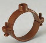
29 Pipe Hangers B3198H - Hinged Extension Split Pipe Clamp (TOLCO Fig. 302) Size Range: 3 /8 (10mm) to 3 (80mm) pipe Material: Malleable Iron Function: Designed for suspending non-insulated pipe horizontally or vertically. pprovals: Conforms to Federal Specification WW-H-171E & , Type 25 and Manufacturers Standardization Society NSI/MSS SP-69 & SP-58, Type 12. Standard Finish: Plain or Electro-Galvanized Order By: Figure number and finish. C (Rod Size) Hanger Rod Not Included Pipe Size Rod Size C Design Load pprox. Wt./100 Part No. in. (mm) in. (mm) Lbs. kn Lbs. kg B3198H- 3 /8 3 /8" (10) 3 /8" /32" (24.6) 180 (.80) 9 (4.1) B3198H- 1 /2 1 /2" (15) 3 /8" /16" (27.0) 180 (.80) 12 (5.4) B3198H- 3 /4 3 /4" (20) 3 /8" /32" (30.9) 180 (.80) 12 (5.4) B3198H-1 1" (25) 3 /8" /32" (34.1) 180 (.80) 13 (5.9) B3198H-1 1 /4 1 1 /4" (32) 3 /8" /32" (39.7) 180 (.80) 18 (8.1) B3198H-1 1 /2 1 1 /2" (40) 3 /8" /32" (43.6) 180 (.80) 21 (9.5) B3198H-2 2" (50) 3 /8"-16 2" (50.8) 180 (.80) 44 (19.9) B3198H-2 1 /2 2 1 /2" (65) 1 /2" /32" (59.5) 300 (1.33) 73 (33.1) B3198H-3 3" (80) 1 /2" /32" (69.0) 300 (1.33) 95 (43.1) B3198HCT - Hinged Extension Split Pipe Clamp (TOLCO Fig. 301CT) Size Range: 1 /2 (15mm) to 2 (50mm) copper tubing Material: Malleable Iron Function: rigid support to suspend tubing horizontally or vertically. pprovals: Conforms to Federal Specification WW-H-171E & , Type 25 and Manufacturers Standardization Society NSI/MSS SP-69 & SP-58, Type 12. Standard Finish: DUR-COPPER Order By: Figure number and finish. C (Rod Size) Hanger Rod Not Included Pipe Hangers Tubing Size Rod Size C Design Load pprox. Wt./100 Part No. in. (mm) in. (mm) Lbs. (kn) Lbs. (kg) B3198HCT- 1 /2 1 /2" (15) 3 /8"-16 5 /8" (15.9) 180 (.80) 8 (3.6) B3198HCT- 3 /4 3 /4" (20) 3 /8" /16" (20.6) 180 (.80) 10 (4.5) B3198HCT-1 1" (25) 3 /8" /16" (23.8) 180 (.80) 10 (4.5) B3198HCT-1 1 /4 1 1 /4" (32) 3 /8" /8" (28.6) 180 (.80) 14 (6.3) B3198HCT-1 1 /2 1 1 /2" (40) 3 /8" /16" (39.7) 180 (.80) 18 (8.1) B3198HCT-2 2" (50) 3 /8" /8" (47.6) 180 (.80) 23 (10.4) 25
30 Pipe Hangers Fig U Hanger Size Range: Size 3 /4" (20mm) thru 8" (200mm) pipe Material: Steel Function: Used to support piping from wood beams where no contraction is expected. Used extensively in automatic fire sprinkler systems. pprovals: Complies with requirements of National Fire Protection ssociation (NFP), Pamphlet 13. Maximum Temperature: 750 F (399 C) Finish: Plain. Contact B-Line for alternative finishes and materials. Order By: Figure number, pipe size, length and finish Length (Specify) Pipe Hangers Pipe Size Fastener Size Part No. in. (mm) in. (mm) /4 3 /4" (20) 5 /16" (7.9) 16 x 2* " (25) 5 /16" (7.9) 16 x 2* /4 1 1 /4" (32) 5 /16" (7.9) 16 x 2* /2 1 1 /2" (40) 5 /16" (7.9) 16 x 2* " (50) 5 /16" (7.9) 16 x 2* /2 2 1 /2" (65) 3 /8" (9.5) 3 /8 x 2 1 /2** " (80) 3 /8" (9.5) 3 /8 x 2 1 /2** /2 3 1 /2" (90) 3 /8" (9.5) 3 /8 x 2 1 /2** " (100) 3 /8" (9.5) 1 /2 x 3** " (125) 1 /2" (12.7) 1 /2 x 3** " (150) 1 /2" (12.7) 1 /2 x 3** " (200) 1 /2" (12.7) 5 /8 x 3** * Drive Screw ** Lag Bolt 26

 16 x 2* 120MJ-1 1 /4 1 1 /4\" (32) 5 /16\" (7.9) 16 x 2* 120MJ-1 1 /2 1 1 /2\" (40) 5 /16\" (7.9) 16 x 2* 120MJ-2 2\" (50) 5 /16\" (7.9) 16 x 2* 120MJ-2 1 /2 2 1 /2\" (65) 3 /8\" (9.")
31 Pipe Hangers Fig. 120MJ - Mutt & Jeff U Hanger Size Range: Size 3 /4" (20mm) thru 8" (200mm) pipe Material: Steel Function: Used to support piping from wood beams where no contraction is expected. Used extensively in automatic fire sprinkler systems. Fig. 120MJ is used when the wood beam is on a diagonal. Finish: Plain. Contact B-Line for alternative finishes and materials. Order By: Figure number, side length and finish Pipe Size Fastener Size Part No. in. (mm) in. (mm) 120MJ- 3 /4 3 /4" (20) 5 /16" (7.9) 16 x 2* 120MJ-1 1" (25) 5 /16" (7.9) 16 x 2* 120MJ-1 1 /4 1 1 /4" (32) 5 /16" (7.9) 16 x 2* 120MJ-1 1 /2 1 1 /2" (40) 5 /16" (7.9) 16 x 2* 120MJ-2 2" (50) 5 /16" (7.9) 16 x 2* 120MJ-2 1 /2 2 1 /2" (65) 3 /8" (9.5) 3 /8 x 2 1 /2** 120MJ-3 3" (80) 3 /8" (9.5) 3 /8 x 2 1 /2** 120MJ-3 1 /2 3 1 /2" (90) 3 /8" (9.5) 3 /8 x 2 1 /2** 120MJ-4 4" (100) 3 /8" (9.5) 1 /2 x 3** 120MJ-5 5" (125) 1 /2" (12.7) 1 /2 x 3** 120MJ-6 6" (150) 1 /2" (12.7) 1 /2 x 3** 120MJ-8 8" (200) 1 /2" (12.7) 5 /8 x 3** * Drive Screw ** Lag Bolt Length (Specify) Fig. 120W - Wrap round U Hanger Size Range: Size 3 /4" (20mm) thru 2" (50mm) pipe Material: Steel Function: Required for automatic fire protection agencies to be used on the end of branch lines to prevent pipe from whipping vertical and striking ceiling or beam. Finish: Plain. Contact B-Line for alternative finishes and materials. Order By: Figure number, side length and finish Pipe Hangers Length (Specify) Pipe Size Fastener Size Part No. in. (mm) in. (mm) 120W- 3 /4 3 /4" (20) 5 /16" (7.9) 16 x 2* 120W-1 1" (25) 5 /16" (7.9) 16 x 2* 120W-1 1 /4 1 1 /4" (32) 5 /16" (7.9) 16 x 2* 120W-1 1 /2 1 1 /2" (40) 5 /16" (7.9) 16 x 2* 120W-2 2" (50) 5 /16" (7.9) 16 x 2* * Drive Screw 27
 Retrofit Wrap round U Hanger Clamp Pipe Hangers Size Range: 1\" (25mm) thru 6\" (150mm) pipe Material: Steel Function: Designed to restrain movement of the pipe within standard")
32 Pipe Hangers Fig. 120RW - (Model B) Retrofit Wrap round U Hanger Clamp Pipe Hangers Size Range: 1" (25mm) thru 6" (150mm) pipe Material: Steel Function: Designed to restrain movement of the pipe within standard U-hangers as required by NFP 13. Where retrofit capability is crucial, the Fig. 120RW is a labor efficient alternative to the standard B-Line Fig. 120W wrap around U-hanger. Fig. 120RW can also be used in new installations. Features Installs easily by tightening two hex nuts. Features a unique bracing slot that locks onto a standard U-hanger to become a solid unit that will stabilize the pipe during seismic activity or sprinkler head activation. Designed to be used in retrofit or new construction applications. Will clamp to existing U-Hangers without restriction to leg angle. pprovals: Underwriters Laboratories listed in the US (UL) and Canada (cul) as a restrainer. NFP 13 (2010) Finish: Plain and Galvanized. Contact B-Line for alternative finishes and materials. Order By: Figure number, type numbers and pipe size Ordering Note: Order by the following type and pipe size: Type 1 (1" (25mm) and 1 1 /4" (32mm) pipe size) Type 2 (1 1 /2" (40mm) and 2" (50mm) pipe size) Type 3 (2 1 /2" (65mm) and 3" (80mm) pipe size) Type 4 (4" (100mm) pipe size) Type 6 (5" (125mm) and 6" (150mm) pipe size) Important Note: The bracing slot feature is sized to fit the U-Hanger rod schedule as required by NFP 13 as follows: 5 /16" (7.9mm) rod for up to 2" (50mm) pipe 3 /8" (9.5mm) rod for 2 1 /2" (65mm) - 6" (160mm) pipe For other rod size requirements consult factory. Type Pipe Size Part No. in. (mm) 120RW-TYPE " (20) 120RW-TYPE1-1 1 / /4" (25) 120RW-TYPE2-1 1 / /2" (40) 120RW-TYPE " (50) 120RW-TYPE3-2 1 / /2" (65) 120RW-TYPE " (80) 120RW-TYPE4-3 1 / /2" (90) 120RW-TYPE " (100) 120RW-TYPE " (125) 120RW-TYPE " (150) 28
 Size Range: (B3373) 1 /2\" (15mm) thru 30\" (760mm) pipe (B3373C) 1 /2\" (15mm) thru 6\" (150mm) pipe Material: Steel Function: Used for supporting vertical piping.")
 Finish: Plain.")
 in. (mm) Bolt Size Lbs. (kg) B3373-1 /2 1 /2\" (15) 9\" (228.6) 3 /8\"-16 x 1 1 /4\" 101 (45.")
33 Pipe Clamps B Standard Riser Clamp (TOLCO Fig. 6) B3373C - PVC Coated Standard Riser Clamp (TOLCO Fig. 6PVC) Size Range: (B3373) 1 /2" (15mm) thru 30" (760mm) pipe (B3373C) 1 /2" (15mm) thru 6" (150mm) pipe Material: Steel Function: Used for supporting vertical piping. pprovals: Underwriters Laboratories Listed in the US (UL), Canada (cul) 3 /4" (20mm) - 8" (200mm). Factory Mutual Engineering pproved, 3 /4" (20mm) thru 8" (200mm). Conforms to Federal Specification WW-H-171E & , Type 8, and Manufacturers Standardization Society NSI/MSS SP-69 & SP-58, Type 8. Maximum Temperature: 650 F (343 C) Finish: Plain. Contact B-Line for alternative finishes and materials. Order By: Figure number, pipe size and finish. Bolt Size Design Load Designed to meet or exceed requirements of FM DS 2-0. L Bolts and Nuts Included B3373C Pipe Size L pprox. Wt./100 Part No. in. (mm) in. (mm) Bolt Size Lbs. (kg) B /2 1 /2" (15) 9" (228.6) 3 /8"-16 x 1 1 /4" 101 (45.9) B /4 3 /4" (20) 9 1 /4" (234.9) 3 /8"-16 x 1 1 /4" 105 (47.7) B " (25) 9 9 /16" (242.9) 3 /8"-16 x 1 1 /4" 109 (49.4) B /4 1 1 /4" (32) 10" (254.0) 3 /8"-16 x 1 1 /4" 112 (50.9) B /2 1 1 /2" (40) 10 1 /4" (260.3) 3 /8"-16 x 1 1 /2" 113 (51.1) B " (50) 10 3 /4" (273.0) 3 /8"-16 x 1 1 /2" 165 (75.0) B /2 2 1 /2" (65) 11 1 /4" (285.7) 3 /8"-16 x 1 1 /2" 180 (81.6) B " (80) /16" (303.2) 3 /8"-16 x 1 1 /2" 195 (88.4) B /2 3 1 /2" (90) 12 3 /8" (314.3) 1 /2"-13 x 1 3 /4" 217 (98.5) B " (100) 12 7 /8" (327.0) 1 /2"-13 x 1 3 /4" 228 (103.5) B " (125) 14" (355.6) 1 /2"-13 x 1 3 /4" 480 (217.7) B " (150) 15 3 /16" (385.8) 1 /2"-13 x 2" 526 (238.6) B " (200) 17 3 /4" (450.8) 5 /8"-11 x 2 1 /2" 957 (434.1) B " (250) 19 7 /16" (493.7) 5 /8"-11 x 2 1 /2" 1101 (499.4) B " (300) /16" (550.9) 5 /8"-11 x 3" 1622 (735.7) B " (350) 23 9 /16" (598.5) 5 /8"-11 x 3" 1732 (785.6) Notes: For ductile iron (D.I.) pipe use part number B3373DI-pipe size. Contact B-Line Engineering for more information. For larger sizes, consult the full line pipe hanger catalog. Pipe Clamps 29

 B3132-4 4\" (100) 12 7 /8\" (327.0) 9 3 /4\" (247.6) 5\" (127.0) 1 /2\" x 2\" (12.7 x 50.8) 5 /8\"-11 x 3\" 864 (391.9) B3132-6 6\" (150) 14 3 /4\" (374.6) 12\" (304.8) 7 1 /16\" (179.4) 1 /2\" x 2\" (12.")
 16 1 /2\" (419.1) 11 3 /8\" (288.9) 1 /2\" x 2\" (12.7 x 50.8) 5 /8\"-11 x 3\" 1409 (639.1) B3132-12 12\" (300) 21 7 /8\" (555.6) 18 7 /8\" (479.4) 13 1 /2\" (342.9) 1 /2\" x 2\" (12.7 x 50.8) 5 /8\"-11 x 3\" 1608 (729.")
 3 /4\" x 4\" (19.0 x 101.6) 1\"-8 x 4 1 /2\" 6403 (2904.4) B3132-18 18\" (450) 31 3 /8\" (796.9) 27 5 /8\" (701.7) 20\" (508.0) 3 /4\" x 4\" (19.0 x 101.6) 1 1 /4\"-7 x 5\" 7293 (3308.")
 3 /4\" x 5\" (19.0 x 127.0) 1 1 /4\"-6 x 5 1 /2\" 11659 (5288.5) Pipe Clamps B3132W - Lug Washer (TOLCO Fig.")
34 Pipe Clamps B Two-Bolt Underground Clamp (TOLCO Fig. 9) Size Range: 4" (100mm) thru 24" (600mm).W.W.. pipe Material: Steel Steel Size Function: Clamp is used for underground.w.w.. cast iron and ductile iron water pipe to prevent joints from separating. The O.D. of the.w.w.. pipe is shown in the data table. Finish: Plain. Contact B-Line for alternative finishes and materials. Order By: Figure number, pipe size and outside diameter of pipe. Order B3132W lugs, tie rods and hex nuts separately. Bolts and Nuts Included B Bolt Size Pipe Size B Clamp I.D. Steel Size pprox. Wt./100 Part No. in. (mm) in. (mm) in. (mm) in. (mm) in. (mm) Bolt Size Lbs. (kg) B " (100) 12 7 /8" (327.0) 9 3 /4" (247.6) 5" (127.0) 1 /2" x 2" (12.7 x 50.8) 5 /8"-11 x 3" 864 (391.9) B " (150) 14 3 /4" (374.6) 12" (304.8) 7 1 /16" (179.4) 1 /2" x 2" (12.7 x 50.8) 5 /8"-11 x 3" 1020 (462.6) B " (200) 17 1 /4" (438.1) 14 1 /4" (361.9) 9 3 /16" (233.4) 1 /2" x 2" (12.7 x 50.8) 5 /8"-11 x 3" 1222 (554.3) B " (250) 19 3 /8" (492.1) 16 1 /2" (419.1) 11 3 /8" (288.9) 1 /2" x 2" (12.7 x 50.8) 5 /8"-11 x 3" 1409 (639.1) B " (300) 21 7 /8" (555.6) 18 7 /8" (479.4) 13 1 /2" (342.9) 1 /2" x 2" (12.7 x 50.8) 5 /8"-11 x 3" 1608 (729.4) B " (350) 26" (660.4) 22 1 /4" (565.1) 15 3 /4" (400.0) 3 /4" x 3" (19.0 x 76.2) 7 /8"-9 x 4 1 /2" 4359 (1977.2) B " (400) 28 3 /8" (720.7) 24 5 /8" (625.5) 17 7 /8" (454.0) 3 /4" x 4" (19.0 x 101.6) 1"-8 x 4 1 /2" 6403 (2904.4) B " (450) 31 3 /8" (796.9) 27 5 /8" (701.7) 20" (508.0) 3 /4" x 4" (19.0 x 101.6) 1 1 /4"-7 x 5" 7293 (3308.1) B " (500) 33 1 /2" (850.9) 29 3 /4" (755.6) 22 1 /8" (562.0) 3 /4" x 4 1 /2" (19.0 x 114.3) 1 1 /4"-7 x 5" 8778 (3981.7) B " (600) 39" (990.6) 35 1 /4" (895.3) 26 3 /8" (669.9) 3 /4" x 5" (19.0 x 127.0) 1 1 /4"-6 x 5 1 /2" (5288.5) Pipe Clamps B3132W - Lug Washer (TOLCO Fig. 9X) Size Range: 3 /4" (20mm) thru 1 1 /2" (40mm) rod Material: Cast Iron Function: Used with B3132 to secure tie rods. The projecting lug bears against the clamp bolt to prevent washer and tie rod from slipping off clamp. Finish: Plain. Contact B-Line for alternative finishes and materials. Order By: Figure number, rod size and finish E B3132W- 3 /4 G D Dia. H F B3132W-1 thru 1 1 /2 E G D Dia. H Tie Rod Use With Pipe Size Dia. E F G H pprox. Wt./100 Part No. Size in. (mm) in. (mm) in. (mm) in. (mm) in. (mm) in. (mm) Lbs. (kg) B3132W- 3 /4 3 /4"-10 4"-12" ( ) 7 /8" (22.2) 2 3 /8" (60.3) /8" (15.9) 1 5 /8" (41.3) 74 (33.7) B3132W-1 1"-8 14"-16" ( ) 1 1 /8" (28.6) 3 1 /2" (88.9) 3 1 /2" (88.9) 5 /8" (15.9) 2 1 /2" (63.5) 207 (93.9) B3132W-1 1 /4 1 1 /4"-7 18" (450) 1 3 /8" (34.9) 3 1 /2" (88.9) 4" (101.6) 5 /8" (15.9) 3 1 /2" (63.5) 236 (107.0) B3132W-1 3 /8 1 3 /8"-6 20" (500) 1 1 /2" (38.1) 4" (101.6) 4 1 /4" (107.9) 5 /8" (15.9) 4" (101.6) 231 (104.8) B3132W-1 1 /2 1 1 /2"-6 24" (600) 1 5 /8" (41.3) 4" (101.6) 4 3 /4" (120.6) 5 /8" (15.9) 4" (101.6) 259 (117.5) 30

 in.")
35 Pipe Clamps B Double Bolt Underground Socket Clamp (TOLCO Fig. 14) Size Range: 4" (100mm) thru 24" (600mm).W.W.. pipe Material: Steel Function: Clamp is used for underground.w.w.. cast iron and ductile iron water pipe to prevent joints from separating. The O.D. of the.w.w.. pipe is shown in the data table. pprovals: Conforms to National Fire Protection ssociation (NFP) Pamphlet 24, 4" (100mm) thru 12" (300mm) pipe sizes. Finish: Plain. Contact B-Line for alternative finishes and materials. Order By: Figure number, pipe size and outside diameter of pipe. Order B3134W plate washers, tie rods and hex nuts separately. B Part Pipe Size B Bolt B3134 Washer Size pprox. Wt./100 No. in. (mm) in. (mm) in. (mm) Size lbs. (kg) B " (121.9) 14 1 /16" (357.2) 9 5 /16" (236.5) 5 /8"-11 B3134W- 3 / (578.3) B " (175.3) 16 7 /16" (417.5) /16" (298.9) 5 /8"-11 B3134W- 3 / (660.0) B " (229.9) 19 5 /8" (498.5) 14 7 /8" (442.6) 5 /8"-11 B3134W- 3 / (1065.9) B " (281.9) /16" (554.0) 17 1 /16" (433.4) 3 /4"-10 B3134W- 3 / (1326.8) B " (335.3) 24 1 /2" (622.3) 19 1 /4" (488.9) 7 /8"-9 B3134W (1828.0) B " (388.6) /16" (684.2) /16" (550.9) 7 /8"-9 B3134W (2442.6) B " (441.9) 30 3 /4" (781.0) 24 3 /4" (628.6) 1"-8 B3134W-1 1 / (3467.8) B " (495.3) 34 5 /16" (871.5) 27 5 /16" (693.7) 1 1 /4"-7 B3134W-1 1 / (4275.2) B " (548.6) 36 5 /8" (930.3) 29 5 /8" (752.5) 1 1 /4"-7 B3134W-1 1 / (4978.2) B " (655.3) 42 1 /8" (1070.0) 34 3 /8" (873.1) 1 1 /2"-6 B3134W-1 1 / (6742.6) B3134W - Plate Washer (TOLCO Fig. 14X) Size Range: 3 /4"-10 thru 1 1 /2"-6 rod Material: Steel Function: Used with B3134 to secure tie rods. Finish: Plain. Contact B-Line for alternative finishes and materials. Order By: Figure number, rod size and finish C B Pipe Clamps Tie Rod Hole Size pprox. Part Size B C Wt./100 No. in. (mm) in. (mm) in. (mm) lbs. (kg) B3132W- 3 /4 3 /4"-10 3" (76.2) 1 /2" (12.7) 7 /8" (22.2) 120 (54.4) B3132W-1 1" /2" (88.9) 1 /2" (12.7) 1 1 /8" (28.6) 157 (71.2) B3132W-1 1 /8 1 1 /8" /2" (88.9) 5 /8" (15.9) 1 1 /4" (31.7) 194 (88.0) B3132W-1 1 /4 1 1 /4" /2" (88.9) 3 /4" (19.0) 1 3 /8" (35.8) 230 (104.3) B3132W-1 1 /2 1 1 /2" /2" (88.9) 3 /4" (19.0) 1 5 /8" (41.2) 240 (108.8) 31

, Canada (cul) 3 /4\" (20mm) - 12\" (300mm), and approved by Factory Mutual Engineering (FM), 3 /4\" (20mm) - 8\" (200mm).")
 felt on each half of clamp.")
36 Pipe Clamps B Standard Pipe Clamp (TOLCO Fig. 4) B3140C - Standard Pipe Clamp PVC Coated (TOLCO Fig. 4PVC) Size Range: B3140/B3140C Size 1 /2" (15mm) thru 12" (300mm) pipe. Material: Steel Function: Recommended for the suspension of non-insulated pipe or insulated pipe with B3151 shields. (Use B3200 weldless eye nut, B3210 eye rod or B3211 welded eye rod.) B3140F and B3140C are designed to reduce noise and vibration and/or prevent electrolysis. pprovals: Underwriters Laboratories Listed in the US (UL), Canada (cul) 3 /4" (20mm) - 12" (300mm), and approved by Factory Mutual Engineering (FM), 3 /4" (20mm) - 8" (200mm). Federal Specification WW-H-171E & , Type 4, and Manufacturers Standardization Society NSI/MSS SP-69 & SP-58, Type 4. Note: For piping that requires sway bracing refer to Fig. 4. Maximum Temperature: 750 F (399 C) Finish: Plain. Contact B-Line for alternative finishes and materials. Order By: Figure number, pipe size and finish. Order Note: When ordering B3140F allow for 3 /16" (4.8mm) felt on each half of clamp. B C B C Bolt Size Designed to meet or exceed requirements of FM DS 2-0. B3140 B3140C Pipe Clamps Pipe pprox. Part Size B C Bolt Wt./100 No. in. (mm) in. (mm) in. (mm) in. (mm) Size lbs. (kg) B /2 1 /2" (15) 3 /8" (9.5) 31 /32" (24.6) 1 17 /32" (38.9) 5 /16" (13.6) B /4 3 /4" (20) 9 /16" (14.3) 1 3 /32" (27.8) 1 21 /32" (42.0) 5 /16" (14.0) B " (25) 9 /16" (14.3) 1 5 /16" (33.3) 1 7 /8" (47.6) 5 /16" (14.5) B /4 1 1 /4" (32) 17 /32" (13.5) 1 7 /16" (36.5) 2" (50.8) 5 /16" (17.7) B /2 1 1 /2" (40) 19 /32" (15.1) 1 21 /32" (42.0) 2 7 /32" (56.4) 5 /16" (18.6) B " (50) 9 /16" (14.3) 2 1 /8" (54.0) 2 3 /4" (69.8) 1 /2" (53.5) B /2 2 1 /2" (65) 5 /8" (15.9) 2 21 /32" (67.5) 3 9 /32" (83.3) 1 /2" (58.9) B " (75) 5 /8" (15.9) 2 15 /16" (74.6) 3 9 /16" (90.5) 1 /2" (68.0) B /2 3 1 /2" (90) 5 /8" (15.9) 3 5 /32" (80.1) 3 25 /32" (96.0) 1 /2" (71.6) B " (100) 3 /4" (19.0) 3 9 /16" (90.5) 4 5 /16" (109.5) 5 /8" (108.4) B " (125) 3 /4" (19.0) 4 1 /8" (104.8) 4 7 /8" (123.8) 5 /8" (123.4) B " (150) 7 /8" (22.2) 4 15 /16" (125.4) 5 13 /16" (147.6) 3 /4" (245.4) B " (200) 1" (25.4) 6 1 /16" (154.0) 6 15 /16" (176.2) 3 /4" (291.2) B " (250) 1" (25.4) 7 3 /8" (187.3) 8 11 /16" (220.7) 7 /8" (619.6) B " (300) 1" (25.4) 8 7 /16" (214.3) 9 3 /4" (247.6) 7 /8" (699.9) 32
37 Pipe Clamps Figure 4B Pipe Clamp (B-Line B386) Size Range: 3 /4 (20mm) to 8 (200mm) pipe Material: Steel Function: Recommended for the suspension of non-insulated pipe or insulated pipe with B3151 (Fig. 220) shields. pprovals: Underwriter's Laboratories Listed in the US (UL) and Canada (cul) for 3 /4 (20mm) thru 8 (200mm) pipe. Standard Finish: Plain or Electro-Plated, Contact B-Line for alternative finishes and materials. Order By: Figure number and finish. C B D Pipe Size Rod Size B C D Bolt Size Design Load pprox. Wt./100 Part No. in. (mm) in. (mm) in. (mm) in. (mm) Lbs. (kn) Lbs. (kg) 4B- 3 /4 3 /4" (20) 3 /8"-16 1" (25.4) 2 7 /8" (73.0) 2 5 /8" (66.7) 5 /16" (1.47) 56 (25.4) 4B-1 1" (25) 3 /8"-16 1" (25.4) 3 1 /4" (82.5) 2 15 /16" (74.6) 5 /16" (1.47) 60 (27.2) 4B-1 1 /4 1 1 /4" (32) 3 /8"-16 1" (25.4) 3 9 /16" (90.6) 3 1 /4" (82.5) 5 /16" (1.47) 74 (33.5) 4B-1 1 /2 1 1 /2" (40) 3 /8"-16 1" (25.4) 3 13 /16" (96.8) 3 7 /16" (87.3) 5 /16" (1.47) 79 (35.8) 4B-2 2" (50) 3 /8" /2" (38.1) 5 1 /8" (130.2) 4 5 /8" (117.5) 5 /16" (1.78) 156 (70.7) 4B-2 1 /2 2 1 /2" (65) 1 /2" /4" (44.4) 5 5 /8" (142.9) 5 3 /8" (136.5) 3 /8" (1.78) 176 (79.8) 4B-3 3" (80) 1 /2" /8" (47.6) 6 3 /4" (171.4) 6 1 /8" (155.5) 3 /8" (2.93) 198 (89.9) 4B-3 1 /2 3 1 /2" (90) 1 /2"-13 2" (50.8) 7 1 /4" (184.1) 6 3 /4" (171.4) 3 /8" (2.93) 219 (99.3) 4B-4 4" (100) 5 /8"-11 2" (50.8) 8 5 /8" (219.1) 7 1 /4" (184.1) 1 /2" (3.56) 288 (130.6) 4B-5 5" (125) 5 /8"-11 2" (50.8) 9 7 /8" (250.8) 8 5 /16" (211.1) 5 /8" (4.36) 390 (176.9) 4B-6 6" (150) 3 /4" /8" (54.0) /16" (277.8) 9 1 /2" (241.3) 5 /8" (4.36) 448 (203.2) 4B-8 8" (200) 7 /8" /8" (54.0) 13 7 /16" (341.2) 11 1 /2" (292.1) 3 /4" (5.34) 691 (313.4) Pipe Clamps 33

38 Pipe Clamps B Standard Pipe Strap (TOLCO Fig. 2STR) Size Range: 1 /2" (15mm) thru 24" (600mm) pipe Material: Steel Function: Designed for supporting pipe runs from strut supports. pprovals: Underwriters Laboratories Listed for B /4" thru B2400-8". Conforms to Federal Specification WW-H-171E & , Type 26 and Manufacturers Standardization Society NSI/MSS SP-69 & SP-58, Type 26. Finish: Electro-Galvanized. Contact B-Line for alternative finishes and materials. Order By: Figure number, pipe size and finish Note: Ductile iron sizes available. Special B dimensions available on request, consult factory. Design Load 3 Pipe Size C Design Load 1 B Bolt Size T W Design Load 2 Part No. Pipe Size B C T W in. (mm) in. (mm) in. (mm) in. (mm) in. (mm) in. (mm) Pipe Clamps B /2 1 /2 (15) 5 /16 (7.9) 7 /16 (11.1) 2 13 /16 (71.4) 10 Ga. (3.4) 1 5 /8 (41.3) B /4 3 /4 (20) 5 /16 (7.9) 7 /16 (11.1) 3 (76.2) 10 Ga. (3.4) 1 5 /8 (41.3) B (25) 5 /16 (7.9) 7 /16 (11.1) 3 17 /32 (89.7) 10 Ga. (3.4) 1 5 /8 (41.3) B /4 1 1 /4 (32) 5 /16 (7.9) 7 /16 (11.1) 3 3 /4 (95.2) 10 Ga. (3.4) 1 5 /8 (41.3) B /2 1 1 /2 (40) 5 /16 (7.9) 7 /16 (11.1) 4 1 /16 (103.2) 10 Ga. (3.4) 1 5 /8 (41.3) B (50) 7 /16 (11.1) 11 /16 (17.4) 5 21 /32 (143.6) 1 /4 (6.3) 1 5 /8 (41.3) B /2 2 1 /2 (65) 7 /16 (11.1) 11 /16 (17.4) 6 5 /32 (156.3) 1 /4 (6.3) 1 5 /8 (41.3) B (80) 7 /16 (11.1) 11 /16 (17.4) 6 25 /32 (172.2) 1 /4 (6.3) 1 5 /8 (41.3) B /2 3 1 /2 (90) 7 /16 (11.1) 11 /16 (17.4) 7 9 /32 (184.9) 1 /4 (6.3) 1 5 /8 (41.3) B (100) 9 /16 (14.3) 11 /16 (17.4) 7 25 /32 (197.6) 1 /4 (6.3) 1 5 /8 (41.3) B (125) 9 /16 (14.3) 11 /16 (17.4) 8 7 /8 (225.4) 1 /4 (6.3) 1 5 /8 (41.3) B (150) 9 /16 (14.3) 11 /16 (17.4) 9 15 /16 (252.4) 1 /4 (6.3) 1 5 /8 (41.3) B (200) 9 /16 (14.3) 11 /16 (17.4) /32 (304.0) 1 /4 (6.3) 1 5 /8 (41.3) Part No. Design Load 1 Design Load 2 Design Load 3 pprox. Wt./100 Lbs. (kn) Lbs. (kn) Lbs. (kn) Lbs. (kg) B /2 600 (2.67) 150 (.67) 105 (.47) 23 (10.4) B /4 600 (2.67) 150 (.67) 105 (.47) 26 (11.8) B (2.67) 150 (.67) 120 (.53) 31 (14.0) B /4 600 (2.67) 150 (.67) 120 (.53) 36 (16.3) B /2 600 (2.67) 150 (.67) 120 (.53) 39 (17.7) B (5.34) 480 (2.14) 180 (.80) 93 (42.2) B / (5.34) 480 (2.14) 180 (.80) 106 (48.1) B (5.34) 480 (2.14) 300 (1.33) 132 (59.9) B / (5.34) 480 (2.14) 300 (1.33) 151 (68.5) B (6.67) 600 (2.67) 450 (2.00) 160 (72.6) B (6.67) 600 (2.67) 450 (2.00) 192 (87.1) B (6.67) 600 (2.67) 450 (2.00) 219 (99.3) B (8.90) 800 (3.56) 600 (2.67) 297 (134.7) For larger sizes, consult the full line pipe hanger catalog. 34
 Size Range: 3 /4\" (20mm) thru 2\" (50mm) CPVC pipe Material: Pre-Galvanized Steel Function: Intended to")
39 Pipe Clamps Fig Hanger for CPVC Plastic Pipe & IPS Steel Pipe** Single Fastener Strap (B-Line B3181) Size Range: 3 /4" (20mm) thru 2" (50mm) CPVC pipe Material: Pre-Galvanized Steel Function: Intended to perform as a hanger to support CPVC piping used in automatic fire sprinkler systems. The product acts as a hanger when tab is upward and the fastener screw is in the horizontal position. Fig. 22 can be installed on the top of a beam, but in this situation acts as a guide to the piping which is supported by the beam itself. It is not intended to support CPVC pipe from under a flat horizontal surface, such as a ceiling. pprovals: Underwriters Laboratories Listed in the US (UL) and Canada (cul) to support fire sprinkler piping. May be installed in wood using fasteners supplied with product, or into minimum 20 gauge (0.9mm) steel using (1) 1 /4" x 1" tek type screw. Meets and exceeds the requirements of NFP 13, 13R and 13D. Features: Fig. 22 incorporates features which protect the pipe and ease installation. The flared edge design protects CPVC pipe from any rough surface. It is easily attached to the building structure using the special UL Listed hex head self threading screw* furnished with the product. It is recommended that rechargeable electric drills fitted with a hex socket attachment to be used as installation tools. No impact tools (such as a hammer) are allowed. Damage has been known to result from installations using impact type tools. No pre-drilling of a pilot hole in wood is required. Finish: Pre-Galvanized Order By: Figure number and pipe size. * Hardened hex head self threading screw is furnished with the product and is the minimum fastener size acceptable. ** With reduced spacing, consult factory. C B CPVC Max. Hanger Fastener Hex pprox. Pipe Size B C Spacing Head Size Wt./100 Part No. in. (mm) in. (mm) in. (mm) in. (mm) Ft. (m) in. (mm) Lbs. (kg) 22-3 /4 3 /4" (20) 2 7 /16" (61.9) 1 5 /16" (33.3) 1 3 /16" (30.2) 5 1 /2 (1.67) 5 /16" (7.9) 9 (4.1) " (25) 2 11 /16" (68.3) 1 7 /16" (36.5) 1 3 /16" (30.2) 6 (1,83) 5 /16" (7.9) 9 (4.1) /4 1 1 /4" (32) 3 1 /16" (77.8) 1 5 /8" (42.3) 1 3 /16" (30.2) 6 1 /2 (1.98) 5 /16" (7.9) 11 (5.0) /2 1 1 /2" (40) 3 5 /16" (84.1) 1 3 /4" (44.4) 1 3 /16" (30.2) 7 (2.13) 5 /16" (7.9) 12 (5.4) " (50) 3 3 /4" (95.2) 2 1 /8" (54.6) 1 3 /16" (30.2) 8 (2.44) 5 /16" (7.9) 15 (6.8) Pipe Clamps 35
 thru 2\" (50mm) CPVC & steel pipe Material: Pre-Galvanized Steel Function: culus Listed to perform as a hanger and")

40 Pipe Clamps Fig. 22L2 - One Hole Hanger/Restrainer for CPVC & Steel Pipe Size Range: 3 /4" (20mm) thru 2" (50mm) CPVC & steel pipe Material: Pre-Galvanized Steel Function: culus Listed to perform as a hanger and restrainer for CPVC or IPS piping systems. The innovative design also allows for a preferred installation location close to a CPVC fitting without applying damaging compression forces on the pipe which could result in serious Mechanical ESC (Environmental Stress Cracking). pprovals: Underwriters Laboratories Listed in the US (UL) and Canada (cul) to support fire sprinkler piping. May be installed in wood using fasteners supplied with product, or into minimum 20 gauge (0.9mm) steel using (1) 1 /4" x 1" tek type screw. Meets and exceeds the requirements of NFP 13, 13R and 13D. Installation Note: Comes in open position for easier installation. Because of multi structural installation possibilities, specific fastener not included; see notes below for various applications. For Concrete Installation UL requires a minimum test load of 340 lbs for CPVC hangers and 750 lbs for steel pipe hangers; verify anchors meet or exceed these requirements. For Wood Installation Test results have shown that #14 x 1½ wood screws will support the required load for c UL us. For Steel Installation Test results have shown that 1/4 x 1 (min. 20ga steel) Tek type screw will support required UL load. Finish: Pre-Galvanized Order By: Part number Patent Pending B C MOUNTING SURFCE Mounting Surface TB Tab DOWN Down or TB Tab UP Up HNGER/RESTRINER Hanger/Restrainer Pipe Clamps SPRINKLER Sprinkler HED Head HNGER/RESTRINER Hanger/Restrainer Pipe PIPE OD FITTING Fitting OD OD Offset Design OFFSET DESIGN CPVC or Steel Max. Hanger Max. Hanger pprox. Pipe Size B C Spacing - CPVC Spacing - Steel Wt./100 Part No. in. (mm) in. (mm) in. (mm) in. (mm) Ft. (m) Ft. (m) Lbs. (kg) 22L2-3 /4 3 /4" (20) 2 3 /16" (55.6) 15 /16" (23.8) 3 /4" (19.0) 5 1 /2 (1.67) N (N) 9 (4.1) 22L2-1 1" (25) 2 1 /2" (63.5) 1 1 /8" (28.6) 3 /4" (19.0) 6 (1,83) 12 (3.66) 9 (4.1) 22L2-1 1 /4 1 1 /4" (32) 2 13 /16" (71.4) 1 1 /4" (31.7) 3 /4" (19.0) 6 1 /2 (1.98) 12 (3.66) 11 (5.0) 22L2-1 1 /2 1 1 /2" (40) 3 1 /8" (79.4) 1 7 /16" (36.5) 3 /4" (19.0) 7 (2.13) 15 (4.57) 12 (5.4) 22L2-2 2" (50) 3 9 /16" (90.5) 1 5 /8" (41.3) 3 /4" (19.0) 8 (2.44) 15 (4.57) 15 (6.8) 36
 Size Range: 3 /4\" (20mm) thru 3\" (80mm) CPVC pipe Material: Pre-Galvanized Steel Function: Intended to")
41 Pipe Clamps Fig Hanger for CPVC Plastic Pipe & IPS Steel Pipe** Double Fastener Strap (B-Line B3182) Size Range: 3 /4" (20mm) thru 3" (80mm) CPVC pipe Material: Pre-Galvanized Steel Function: Intended to perform as a hanger to support CPVC piping used in automatic fire sprinkler systems. Fig. 23 can be installed on the top, bottom or side of a beam. pprovals: Underwriters Laboratories Listed in the US (UL) and Canada (cul) sizes 3 /4" (20mm) thru 2" (50mm) to support fire sprinkler piping. May be installed in wood using fasteners supplied with product, or into minimum 20 gauge (0.9mm) steel using (2) 1 /4" x 1" tek type screw. Meets and exceeds the requirements of NFP 13, 13R and 13D. Features: Fig. 23 incorporates features which protect the pipe and ease installation. The flared edge design protects the CPVC pipe from any rough surface. It also incorporates snap restrainers allowing easier and faster installation. Easily attaches to the building structure using the two UL Listed hex head self threading screws* furnished with the product. It is recommended that rechargeable electric drills fitted with a hex socket attachment be used as installation tools. No impact tools (such as a hammer) are allowed. Damage has been known to result from installations using impact type tools. No pre-drilling of a pilot hole in wood is required. Finish: Pre-Galvanized Order By: Figure number and pipe size * Hardened hex head self threading screw is furnished with the product and is the minimum fastener size acceptable. ** With reduced spacing, consult factory. C B B CPVC Max. Hanger Fastener Hex pprox. Pipe Size B C Spacing Head Size Wt./100 Part No. in. (mm) in. (mm) in. (mm) in. (mm) Ft. (m) in. (mm) Lbs. (kg) 23-3 /4 3 /4" (20) 3 1 /8" (79.4) 1 9 /16" (39.7) 1 3 /16" (30.2) 5 1 /2 (1.67) 5 /16" (7.9) 9 (4.1) " (25) 3 3 /8" (85.7) 1 11 /16" (42.9) 1 3 /16" (30.2) 6 (1,83) 5 /16" (7.9) 9 (4.1) /4 1 1 /4" (32) 4 3 /16" (106.4) 2 3 /32" (53.1) 1 3 /16" (30.2) 6 1 /2 (1.98) 5 /16" (7.9) 11 (5.0) /2 1 1 /2" (40) 4 7 /16" (112.7) 2 7 /32" (56.3) 1 3 /16" (30.2) 7 (2.13) 5 /16" (7.9) 12 (5.4) " (50) 4 7 /8" (123.8) 2 7 /16" (61.9) 1 3 /16" (30.2) 8 (2.44) 5 /16" (7.9) 15 (6.8) /2 2 1 /2" (65) 5 3 /8" (136.5) 2 11 /16" (68.3) 1 3 /16" (30.2) Consult Factory 5 /16" (7.9) 22 (10.0) " (80) 6" (152.4) 3" (76.2) 1 3 /16" (30.2) Consult Factory 5 /16" (7.9) 25 (11.3) Pipe Clamps 37
 Size Range: 3 /4\" (20mm) thru 2\" (50mm) CPVC pipe Material: Pre-Galvanized Steel Function:")
 and Canada (cul) to support fire sprinkler piping.")
42 Pipe Clamps Fig Hanger for CPVC Plastic Pipe & IPS Steel Pipe** Double Fastener Strap Side Mounted (B-Line B3183) Size Range: 3 /4" (20mm) thru 2" (50mm) CPVC pipe Material: Pre-Galvanized Steel Function: Intended to perform as a hanger to support CPVC piping used in automatic fire sprinkler systems. Can be installed on the top or on the bottom of a beam. pprovals: Underwriters Laboratories Listed in the US (UL) and Canada (cul) to support fire sprinkler piping. May be installed in wood using fasteners supplied with product, or into minimum 20 gauge (0.912mm) steel using (2) 1 /4" x 1" tek type screws. Meets and exceeds the requirements of NFP 13, 13R and 13D. Features: Fig. 24 incorporates features which protect the pipe and ease installation. The flared edge design protects the CPVC pipe from any rough surface. Easily attaches to the building structure using the two UL Listed hex head self threading screws* furnished with the product. It is recommended that rechargeable electric drills fitted with a hex socket attachment be used as installation tools. No impact tools (such as a hammer) are allowed. Damage has been known to result from installations using impact type tools. No pre-drilling of a pilot hole in wood is required. Finish: Pre-Galvanized Order By: Figure number and pipe size * Hardened hex head self threading screw is furnished with the product and is the minimum fastener size acceptable. ** With reduced spacing, consult factory. C B B CPVC Max. Hanger Fastener Hex pprox. Pipe Size B C Spacing Head Size Wt./100 Part No. in. (mm) in. (mm) in. (mm) in. (mm) Ft. (m) in. (mm) Lbs. (kg) 24-3 /4 3 /4" (20) 2 5 /16" (58.7) 1 5 /32" (27.8) 1 3 /16" (30.2) 5 1 /2 (1.67) 5 /16" (7.9) 9 (4.1) " (25) 2 5 /8" (66.7) 1 5 /16" (33.3) 1 3 /16" (30.2) 6 (1.83) 5 /16" (7.9) 9 (4.1) /4 1 1 /4" (32) 3" (76.2) 1 1 /2" (38.1) 1 3 /16" (30.2) 6 1 /2 (1.98) 5 /16" (7.9) 11 (5.0) /2 1 1 /2" (40) 3 1 /4" (82.5) 1 5 /8" (42.3) 1 3 /16" (30.2) 7 (2.13) 5 /16" (7.9) 12 (5.4) " (50) 3 11 /16" (93.7) 1 27 /32" (43.6) 1 3 /16" (30.2) 8 (2.44) 5 /16" (7.9) 15 (6.8) Pipe Clamps Fig Surge Restrainer Size Range: One size fits 3 /4" (20mm) thru 2" (40mm) pipe. Material: Pre-Galvanized Steel Function: Designed to be used in conjunction with Fig. 200 band hangers to restrict the upward movement of piping as it occurs during sprinkler head activation or earthquake type activity. The surge restrainer is easily and efficiently installed by snapping into a locking position on the band hanger. This product is intended to satisfy the requirements as indicated in the National Fire Protection ssociation NFP 13, 2010 edition, and Can be used to restrain either steel pipe or CPVC plastic Pipe. pprovals: Underwriters Laboratories Listed only when used with band hanger Fig. 200, in the US (UL) and Canada (cul). Finish: Pre-Galvanized Order By: Figure number and band hanger, size from 3 /4" (20mm) thru 2" (40mm). Patent #5,344,108 38
 Function: To be used anywhere a screw cannot achieve full embedment due to thickness of wood structural material when installed. Fig.")
43 Pipe Clamps Fig. 27B - Speed Nut Size Range: Fits screws supplied with all CPVC hangers. Material: Steel Finish: Pre-Galvanized (Zinc) Function: To be used anywhere a screw cannot achieve full embedment due to thickness of wood structural material when installed. Fig. 27B allows full pull out load capacity of screws when installed to the standard screws supplied with all CPVC hangers (Fig. 22, 23, 24, 28, 28M, 29, and B3184). Fig. 27B (1) Required High Side of Hanger pplication Fig. 27B (2) Required Hanger pplication Hanger and Restraint pplication Pipe Clamps Fig. 27B (2) Required Fig. 27B (1) Required High Side of Hanger pplication Hanger pplication Hanger and Restraint pplication 39
 through 2\" (50mm) Material: Steel, Pre-Galvanized Function: Designed to be used as a hanger and")
44 Pipe Clamps Fig Stand-Off Hanger & Restrainer for CPVC Plastic Pipe & IPS Steel Pipe ** Size Range: 3 /4" (20mm) through 2" (50mm) Material: Steel, Pre-Galvanized Function: Designed to be used as a hanger and restrainer for CPVC piping where the "stand-off" design will ease installation by eliminating the need for wood blocking. Features: Flared edge design protects CPVC pipe from any rough or abrasive surfaces. Unique twist and lock design holds pipe firmly in place and allows retrofit type of installation. The "Stand-Off" design eliminates the need for wood block extension. Can be installed on horizontal or vertical piping regardless of mounting surface orientation. ttaches easily to wood structure with two hex head self-threading screws furnished with product. Installs easily using rechargeable electrical driver with 5 /16" (7.9mm) extension socket eliminating impact tool damage to pipe. ttaches easily to steel, minimum 18 gauge (1.024mm) with (2) 1 /4" x 1" tek type self drilling tapping screws. UL Listed as a hanger and a restrainer for fire sprinkler piping. pprovals: Underwriters Laboratory Listed in the US (UL) and Canada (cul) to support automatic fire sprinkler systems. May be installed into wood using fasteners supplied with product, or into minimum 18 gauge steel using (2) 1 /4" x 1" tek type screws. Meets and exceeds the requirements of NFP 13, 13R and 13D. Fig. 28 satisfies the UL vertical restraint requirement where needed. UL Listed as a hanger and vertical restraint when installed on 3 /8" (9.5mm) composite wood material. Use two Fig. 27B Speed Nuts when used as a hanger and restraint. Use one Fig. 27B Speed Nut on the upper installed screw when used as a hanger only. Order by: Figure number and pipe size. Pat. # 7,455,268, Pat. # 7,832,248 C B ** With reduced spacing, consult factory. Pipe Clamps Fig. 27B (1) Required High Side of Hanger pplication Fig. 27B (2) Required Hanger pplication Hanger and Restraint pplication Pipe Size B C Max Hanger pprox. Spacing Wt./100 Part No. in. (mm) in. (mm) in. (mm) in. (mm) Ft. (m) lbs. (kg) 28-3 /4 3 /4" (20) 3 1 /32" (77.0) 2" (50.8) 3 1 /2" (88.9) 5 1 /2 (1.67) 18 (8.1) " (25) 3 5 /16" (84.1) 2 3 /16" (55.6) 3 1 /2" (88.9) 6 (1.83) 21 (9.5) /4 1 1 /4" (32) 3 5 /8" (92.1) 2 3 /8" (60.3) 3 1 /2" (88.9) 6 1 /2 (1.98) 23 (10.4) /2 1 1 /2" (40) 4" (101.6) 2 1 /2" (63.5) 3 1 /2" (88.9) 7 (2.13) 31 (14.0) " (50) 4 1 /2" (114.3) 2 11 /16" (68.3) 3 5 /8" (92.1) 8 (2.44) 34 (15.4) 40

45 Fig. 28M - Offset Hanger & Restrainer for CPVC Plastic Pipe and IPS Steel Pipe ** Pipe Clamps Size Range: 3 /4" (20mm) thru 2" (32mm) Material: Steel, Pre-Galvanized Function: Designed to be used as a hanger and restrainer for CPVC piping or steel piping where the stand-off design will ease installation by eliminating the need for wood blocking. Features: Flared edge design protects CPVC pipe from any rough or abrasive surfaces Unique snap-on design holds pipe firmly in place and allows retrofit type of installation The Stand-Off design eliminates the need for wood block extension Can be installed on horizontal or vertical piping regardless of mounting surface orientation ttaches easily to wood structure with two hex head self-threading screws furnished with product Installs easily using rechargeable electrical driver with 5 /16 (7.9mm) extension socket eliminating impact tool damage to pipe ttaches easily to steel, minimum 18 gauge (1.024mm) with (2) 1 /4 x 1 tek type self drilling tapping screws culus Listed as a hanger and a restrainer for fire sprinkler piping Installation Note: When installed in wood structural members and threads from the #10 x 1" screws are exposed, use Fig. 27B speed nut to secure pprovals: Underwriters Laboratory Listed in the US (UL) and Canada (cul) to support automatic fire sprinkler systems. May be installed into wood using fasteners screws. Meets and exceeds the requirements of NFP 13, 13R and 13D. Fig. 28M satisfies the UL vertical restraint requirements where needed. Order By: Figure number and pipe size Patent #7,744,042 ** With reduced spacing, consult factory. Fig. 27B (2) Required C B Hanger and Restraint pplication Restraint Fig. 27B (1) Required High Side of Hanger Pipe Clamps Restraint Detail Hanger pplication Pipe Size Hole Dia. B C Max Spacing* pprox. Wt./100 Part No. in. (mm) in. (mm) in. (mm) in. (mm) in. (mm) lbs. (kg) 28M- 3 /4 3 /4" (20) 2" (50.8) 3 /16" (4.8) 3 5 /16" (84.1) 5-6 (1676) 9 (4.1) 28M-1 1" (25) 2 1 /8" (54.0) 3 /16" (4.8) 3 1 /2" (88.9) 6-0 (1829) 12 (5.4) 28M-1 1 /4 1 1 /4" (32) 2 5 /16" (58.7) 3 /16" (4.8) 3 1 /2" (88.9) 6-6 (1981) 13 (5.9) 28M-1 1 /2 1 1 /2" (49) 2 7 /16" (61.9) 3 /16" (4.8) 3 7 /8" (98.4) 7-0 (2133) 14 (6.3) 28M-2 2" (50) 2 5 /8" (66.7) 3 /16" (4.8) 4 7 /16" (112.7) 8-0 (2438) 15 (6.8) * Required per NFP 13 for CPVC plastic pipe 41
 and 1\" (25mm) pipe sizes Material: Pre-Galvanized Steel Function: Intended to")
46 Pipe Clamps Fig Double Offset Hanger & Restrainer for CPVC Plastic Pipe & IPS Steel Pipe** Size Range: vailable in 3 /4" (20mm) and 1" (25mm) pipe sizes Material: Pre-Galvanized Steel Function: Intended to perform as a hanger and restrainer for CPVC, plastic fire sprinkler pipe. Provides double offset 1 1 /2 (20mm) x 1 1 /2 (20mm) from mounting surface. This design will ease installation by eliminating the need for wood block extension and allow retro-fit attachment of hanger to sprinkler pipe. Features: Thumb tab provides protection to restrain pipe in rough job site conditions. Tab is not required to be bent for listed installation. Offset edge eliminates abrasion. ttaches easily to wood structure with two special #10 x 1 hex head self-threading screws furnished with product. Can be used as a single offset hanger by aligning "dimples" with top of mounting surface and utilizing two fasteners in two of the three holes provided. pprovals: Underwriters Laboratories Listed in the US (UL) and Canada (cul) as a hanger and restrainer to support fire sprinkler systems. Meets and exceeds requirements of NFP 13, 13R and 13D. Finish: Pre-Galvanized Order By: Figure number and pipe size. Patent Pending ** With reduced spacing, consult factory. 1.5 (38.1mm) 1.5 (38.1mm) 1.5 (38.1mm) 1.5 (38.1mm) Pipe Clamps Double Offset Single Offset Install using a rechargeable electric drill fitted with a 5/16 (7.9mm) socket attachment with the special hex head self-tapping screws provided. Install screws until they bottom out. Pipe can be snapped into hanger before or after installation of the screws to the mounting surface. Thumb tab may be bent up to provide additional protection to the pipe, but is not required for performance of the hanger / restrainer function. 42


 and Canada (cul) 3 /4\" (20mm) thru 2\" (50mm) to support automatic fire sprinkler systems.")
47 Pipe Clamps B Offset Hanger for CPVC Plastic Pipe and IPS Steel Pipe Size Range: 3 /4" (20mm) thru 2" (32mm) Material: Pre-Galvanized Steel Function: Designed to be used as a hanger for CPVC piping or steel piping where the stand-off design will ease installation by eliminating the need for wood blocking. Features: Flared edge design protects CPVC pipe from any rough or abrasive surfaces The stand-off design eliminates the need for wood block extension Can be installed on horizontal or vertical piping regardless of mounting surface orientation ttaches easily to wood structure with two hex head self-threading screws furnished with product culus Listed as a hanger for fire sprinkler piping Installation Note: When installed in wood structural members and threads from the #10 x 1" screws are exposed, use Fig. 27B speed nut to secure pprovals: Underwriters Laboratory Listed in the US (UL) and Canada (cul) 3 /4" (20mm) thru 2" (50mm) to support automatic fire sprinkler systems. May be installed into wood using fasteners screws. Meets and exceeds the requirements of NFP 13, 13R and 13D. Order By: Figure number and pipe size Patent # 7,744,042 Pipe Size L H CPVC L H Max. Hanger Fastener Hex pprox. Pipe Size Overall Overall Spacing Head Size Wt./100 Part No. in. (mm) in. (mm) in. (mm) ft. (m) in. (mm) Lbs. (kg) B /4 3 /4" (20) 2 9 /16" (65.1) 4 1 /4" (107.9) 5 1 /2 (1.67) 5 /16" (7.9) 9.0 (4.1) B " (25) 2 13 /16" (71.4) 4 1 /2" (114.3) 6 (1,83) 5 /16" (7.9) 10.0 (4.5) B /4 1 1 /4" (32) 3 3 /16" (81.0) 4 5 /8" (117.5) 6 1 /2 (1.98) 5 /16" (7.9) 12.0 (5.4) B /2 1 1 /2" (40) 3 7 /16" (87.3) 5" (127.0) 7 (2.13) 5 /16" (7.9) 12.0 (5.4) B " (50) 3 7 /8" (98.4) 5" (127.0) 8 (2.44) 5 /16" (7.9) 15.0 (6.8) Pipe Clamps This product is culus Listed as a hanger ONLY. For hanger and restraint applications, please refer to B-Line Fig. 28 (page 39) or Fig. 28M (page 40). 43
 Size Range: 3 /4\" (20mm) thru 6\" (150mm) pipe Material: Steel Function: Designed as an unthreaded base stand for pipe supports B3090, B3094, B3095, B3096, B3097 and B3098.")

 3 /4\" (14.3) 480 (216.0) B3088-1 1 /4 1 /4\" x 6\" x 6\" (6.3 x 152.4 x 152.4) 1 1 /4 (32) 7 /8\" (22.2) 3 /4\" (14.3) 590 (267.6) B3088-1 1 /2 1 /4\" x 6\" x 6\" (6.3 x 152.4 x 152.4) 1 1 /2\" (40) 7 /8\" (22.")
 13 /16\" (14.3) 2376 (1077.7) B3088-3 3 /8\" x 12\" x 12\" (9.5 x 203.2 x 203.2) 3\" (80) 1 1 /2\" (38.1) 13 /16\" (20.6) 3137 (1422.9) B3088-4 1 /2\" x 12\" x 12\" (12.7 x 304.8 x 304.")
48 Pipe Supports B Base Stand (TOLCO Fig. 316) Size Range: 3 /4" (20mm) thru 6" (150mm) pipe Material: Steel Function: Designed as an unthreaded base stand for pipe supports B3090, B3094, B3095, B3096, B3097 and B3098. Finish: Plain or Electro-Galvanized. Contact B-Line for alternative finishes and materials. Order By: Figure number, height and finish. **Height from top of pipe to bottom of plate. Plate Size **Specify Height Stand Pipe Size H 4 Holes Note: Match B3088 part number with dimension 'D' from B3090, B3094, B3095, B3096, B3097 or B3098 charts. Plate Size Stand Pipe Size Dia. H pprox. Wt./100* Part No. in. (mm) in. (mm) in. (mm) in. (mm) Lbs. (kg) B /4 1 /4" x 6" x 6" (6.3 x x 152.4) 3 /4" (20) 7 /8" (22.2) 3 /4" (14.3) 420 (190.5) B /4" x 6" x 6" (6.3 x x 152.4) 1" (25) 7 /8" (22.2) 3 /4" (14.3) 480 (216.0) B /4 1 /4" x 6" x 6" (6.3 x x 152.4) 1 1 /4 (32) 7 /8" (22.2) 3 /4" (14.3) 590 (267.6) B /2 1 /4" x 6" x 6" (6.3 x x 152.4) 1 1 /2" (40) 7 /8" (22.2) 3 /4" (14.3) 655 (297.1) B /4" x 6" x 6" (6.3 x x 152.4) 2" (50) 7 /8" (22.2) 3 /4" (14.3) 1211 (549.3) B /2 3 /8" x 8" x 8" (9.5 x x 203.2) 2 1 /2" (65) 1 1 /4" (31.7) 13 /16" (14.3) 2376 (1077.7) B /8" x 12" x 12" (9.5 x x 203.2) 3" (80) 1 1 /2" (38.1) 13 /16" (20.6) 3137 (1422.9) B /2" x 12" x 12" (12.7 x x 304.8) 4" (100) 1 1 /2" (38.1) 15 /16" (23.8) 4338 (1967.7) B /2" x 18" x 18" (12.7 x x 304.8) 6" (150) 1 1 /2" (38.1) 1 1 /8" (28.6) 7378 (3346.6) *Based on a height of 18" (457.2mm). B3088T - Threaded Base Stand (TOLCO Fig. 316T) Size Range: 1" (25mm) thru 6" (150mm) pipe Material: Steel Function: Designed as a threaded base stand where vertical adjustment is required for pipe supports B3089, B3092, and B3093. Finish: Plain or Electro-Galvanized. Contact B-Line for alternative finishes and materials. Order By: Figure number, height and finish. **Height from top of pipe to bottom of plate. Plate Size **Specify Height TL Thread Length Stand Pipe Size H 4 Holes Note: Match B3088T part number with dimension 'D' from B3089, B3092, and B3093 charts. Pipe Supports Plate Size Stand Pipe Size Dia. H TL pprox. Wt./100* Part No. in. (mm) in. (mm) in. (mm) in. (mm) in. (mm) Lbs. (kg) B3088T-1 1 /4"x 6"x 6" (6.3 x x 152.4) 1" (25) 7 /8" (22.2) 3 /4" (19.0) 1 1 /2" (38.1) 495 (224.5) B3088T-1 1 /4 1 /4"x 6"x 6" (6.3 x x 152.4) 1 1 /4" (32) 7 /8" (22.2) 3 /4" (19.0) 1 1 /2" (38.1) 583 (264.4) B3088T-1 1 /2 1 /4"x 6"x 6" (6.3 x x 152.4) 1 1 /2" (40) 7 /8" (22.2) 3 /4" (19.0) 1 1 /2" (38.1) 649 (294.4) B3088T-2 1 /4"x 6"x 6" (6.3 x x 152.4) 2" (50) 7 /8" (22.2) 3 /4" (19.0) 1 1 /2" (38.1) 785 (356.1) B3088T-2 1 /2 3 /8"x 8"x 8" (9.5 x x 203.2) 2 1 /2" (65) 1 1 /4" (31.7) 13 /16" (20.6) 1 1 /2" (38.1) 1524 (691.3) B3088T-3 3 /8"x 12"x 12" (9.5 x x 304.8) 3" (80) 1 1 /2" (38.1) 13 /16" (20.6) 1 1 /2" (38.1) 2624 (1190.2) B3088T-4 1 /2"x 12"x 12" (12.7 x x 304.8) 4" (100) 1 1 /2" (38.1) 15 /16" (23.8) 2" (50.8) 3594 (1630.2) B3088T-6 1 /2"x 18"x 18" (12.7 x x 457.2) 6" (150) 1 1 /2" (38.1) 1 1 /8" (28.6) 2" (50.8) 7346 (3332.1) *Based on a height of 18" (457.2mm). 44


49 Pipe Supports B3088S - Seismic Base Stand Size Range: 3 /4" (20mm) thru 4" (100mm) pipe Material: Steel Function: Designed as an unthreaded base stand for pipe supports, B3090, B3094, B3095, B3096, B3097 and B3098, to meet requirements of 12X anchor diameter hole spacing for seismic applications. The standard B & B already meet this requirement. Finish: Plain or Electro-Galvanized. Contact B-Line for alternative finishes and materials. Order By: Figure number, height and finish. **Height from top of pipe to bottom of plate. Plate Size **Specify Height Stand Pipe Size H 4 Holes Note: Match B3088S part number with dimension 'D' from B3090, B3094, B3095, B3096, B3097 or B3098 charts. Plate Size Stand Pipe Size Dia. H pprox. Wt./100* Part No. in. (mm) in. (mm) in. (mm) in. (mm) Lbs. (kg) B3088S- 3 /4 1 /4" x 8" x 8" (6.3 x x 203.2) 3 /4" (20) 1" (25.4) 9 /16" (14.3) 618 (280.3) B3088S-1 1 /4" x 8" x 8" (6.3 x x 203.2) 1" (25) 1" (25.4) 9 /16" (14.3) 708 (321.1) B3088S-1 1 /4 1 /4" x 8" x 8" (6.3 x x 203.2) 1 1 /4 (20) 1" (25.4) 9 /16" (14.3) 798 (362.0) B3088S-1 1 /2 1 /4" x 8" x 8" (6.3 x x 203.2) 1 1 /2" (32) 1" (25.4) 9 /16" (14.3) 858 (389.2) B3088S-2 1 /4" x 8" x 8" (6.3 x x 203.2) 2" (50) 1" (25.4) 9 /16" (14.3) 993 (450.4) B3088S-2 1 /2 3 /8" x 8 1 /2" x 8 1 /2" (9.5 x x 215.9) 2 1 /2" (65) 1 1 /4" (31.7) 9 /16" (14.3) 1638 (743.0) B3088S-4 1 /2" x 13 1 /2" x 13 1 /2" (12.7 x x 342.9) 4" (100) 1 1 /2" (38.1) 15 /16" (23.8) 4202 (1906.0) *Based on a height of 18" (457.2mm). B3088ST - Threaded Seismic Base Stand Size Range: 1" (25mm) thru 4" (100mm) pipe Material: Steel Function: Designed as a threaded base stand where vertical adjustment is required for pipe supports B3089, B3092, and B3093, to meet requirements of 12X anchor diameter hole spacing for seismic applications. The standard B & B already meet this requirement. Finish: Plain or Electro-Galvanized. Contact B-Line for alternative finishes and materials. Order By: Figure number, height and finish. **Height from top of pipe to bottom of plate. Plate Size **Specify Height TL Thread Length Stand Pipe Size H 4 Holes Note: Match B3088TS part number with dimension 'D' from B3089, B3092, and B3093 charts. Plate Size Stand Pipe Size Dia. H TL pprox. Wt./100* Part No. in. (mm) in. (mm) in. (mm) in. (mm) in. (mm) Lbs. (kg) B3088ST-1 1 /4" x 8" x 8" (6.3 x x 203.2) 1" (25) 1" (25.4) 9 /16" (14.3) 1 1 /2" (38.1) 708 (321.1) B3088ST-1 1 /4 1 /4" x 8" x 8" (6.3 x x 203.2) 1 1 /4" (32) 1" (25.4) 9 /16" (14.3) 1 1 /2" (38.1) 798 (362.0) B3088ST-1 1 /2 1 /4" x 8" x 8" (6.3 x x 203.2) 1 1 /2" (40) 1" (25.4) 9 /16" (14.3) 1 1 /2" (38.1) 858 (389.2) B3088ST-2 1 /4" x 8" x 8" (6.3 x x 203.2) 2" (50) 1" (25.4) 9 /16" (14.3) 1 1 /2" (38.1) 993 (450.4) B3088ST-2 1 /2 3 /8" x 8 1 /2" x 8 1 /2" (9.5 x x 215.9) 2 1 /2" (65) 1 1 /4" (31.7) 9 /16" (14.3) 1 1 /2" (38.1) 1638 (743.0) B3088ST-4 1 /2" x 13 1 /2" x 13 1 /2" (12.7 x x 342.9) 4" (100) 1 1 /2" (38.1) 15 /16" (23.8) 2" (50.8) 4202 (1906.0) *Based on a height of 18" (457.2mm). Pipe Supports 45
 Size Range: 3 /4\" (20mm) thru 36\" (900mm) pipe Material: Steel with cast iron reducer Function: Designed to support horizontal pipe from floor stanchion where vertical adjustment is required.")

50 Pipe Supports B djustable Pipe Saddle Support with Yoke (TOLCO Fig. 318) Size Range: 3 /4" (20mm) thru 36" (900mm) pipe Material: Steel with cast iron reducer Function: Designed to support horizontal pipe from floor stanchion where vertical adjustment is required. U-bolt and hex nuts are provided to hold pipe securely to saddle. To complete floor stanchion, use with B3088T (page 44) threaded pipe stand. pprovals: Conforms to Federal Specification WW-H-171E & and Manufacturers Standardization Society NSI/MSS SP-69 & SP-58, Type 37. Finish: Plain. Contact B-Line for alternative finishes and materials. Order By: Figure number and finish Notes: Order with B3088T for complete stanchion support. 4" (100mm) thru 12" (300mm) fits both steel and ductile iron pipe. For other ductile iron pipe sizes specify B3092DI - size. 3 (80mm) Ductile Iron uses B /2 Schedule 40 Pipe Size B Center of pipe to bottom of pipe reducer. C Center of pipe to bottom lip of support. D Nominal pipe size of base stand - not included. E U-Bolt Dia. E U-Bolt Dia. Steel Size Gussets on sizes B and larger. D C B Pipe Size Maximum O.D. of Pipe Minimum B Maximum Part No. in. (mm) in. (mm) in. (mm) in. (mm) in. (mm) B /4 3 /4" (19) 1 3 /8" (34.9) 3 /4" (19) 5 3 /4" (146.0) 10 1 /4" (260.3) B " (25) 1 3 /8" (34.9) 3 /4" (19) 5 29 /32" (150.0) /32" (264.3) B /4 1 1 /4" (32) 1 11 /16" (42.9) 3 /4" (19) 6 5 /64" (154.4) /64" (268.7) B /2 1 1 /2" (38) 2" (50.8) 3 /4" (19) 6 1 /4" (158.7) 10 3 /4" (273.0) B " (50) 2 7 /16" (61.9) 3 /4" (19) 6 7 /16" (163.5) /16" (277.8) B /2 2 1 /2" (65) 2 7 /8" (73.0) 1 1 /2" (40) 6 7 /8" (174.6) 11 3 /8" (288.9) B " (80) 3 1 /2" (88.9) 1 1 /2" (40) 7 3 /16" (182.6) /16" (296.9) B /2 3 1 /2" (90) 4" (101.6) 1 1 /2" (40) 7 7 /16" (188.9) /16" (303.2) B " (100) 4 7 /8" (123.8) 2 1 /2" (65) 7 13 /16" (198.4) 12 5 /16" (312.7) B " (125) 5 5 /8" (142.9) 2 1 /2" (65) 8 9 /32" (210.3) /32" (324.6) B " (150) 6 29 /32" (175.4) 2 1 /2" (65) 9 1 /16" (230.2) 13 9 /16" (344.5) B " (200) 9 1 /8" (231.8) 2 1 /2" (65) 10 1 /2" (266.7) 15" (381.0) C D (Not Supplied) E Saddle Steel Size pprox. Wt./100 Part No. in. (mm) in. (mm) in. (mm) in. (mm) Lbs. (kg) Pipe Supports B /4 2" (50.8) 1 1 /2" (38) 1 /4" (6.4) 1 /4" x 1 1 /2" (6.3 x 38.1) 247 (112.0) B /32" (54.8) 1 1 /2" (38) 1 /4" (6.4) 1 /4" x 1 1 /2" (6.3 x 38.1) 257 (116.6) B / /64" (59.1) 1 1 /2" (38) 3 /8" (9.5) 1 /4" x 2" (6.3 x 50.8) 289 (131.1) B /2 2 1 /2" (63.5) 1 1 /2" (38) 3 /8" (9.5) 1 /4" x 2" (6.3 x 50.8) 306 (138.8) B /16" (68.3) 1 1 /2" (38) 3 /8" (9.5) 1 /4" x 2" (6.3 x 50.8) 326 (147.9) B /2 3 1 /8" (79.4) 2 1 /2" (65) 1 /2" (12.7) 1 /4" x 3" (6.3 x 76.2) 651 (295.3) B /16" (87.3) 2 1 /2" (65) 1 /2" (12.7) 1 /4" x 3" (6.3 x 76.2) 716 (324.8) B / /16" (93.7) 2 1 /2" (65) 1 /2" (12.7) 1 /4" x 3" (6.3 x 76.2) 717 (325.2) B /4" (107.9) 3" (80) 1 /2" (12.7) 3 /8" x 3 1 /2" (9.5 x 88.9) 1286 (583.3) B /16" (115.9) 3" (80) 1 /2" (12.7) 3 /8" x 3 1 /2" (9.5 x 88.9) 1321 (599.2) B /2" (139.7) 3" (80) 5 /8" (15.9) 1 /2" x 3 1 /2" (12.7 x 88.9) 1595 (723.5) B " (177.8) 3" (80) 5 /8" (15.9) 1 /2" x 3 1 /2" (12.7 x 88.9) 1815 (823.3) 46
 Size Range: 1\" (25mm) thru 36\" (900mm) pipe Material: Steel with cast iron reducer Function: Designed to support horizontal pipe from floor stanchion where vertical adjustment is required.")
51 Pipe Supports B djustable Pipe Saddle Support (TOLCO Fig. 317) Size Range: 1" (25mm) thru 36" (900mm) pipe Material: Steel with cast iron reducer Function: Designed to support horizontal pipe from floor stanchion where vertical adjustment is required. U-bolt and hex nuts are provided to hold pipe securely to saddle. To complete floor stanchion, use with B3088T (page 44) threaded pipe stand. pprovals: Conforms to Federal Specification WW-H-171E & , Type 38 and Manufacturers Standardization Society NSI/MSS SP-69 & SP-58, Type 37. Schedule 40 Pipe Size B Center of pipe to bottom of pipe reducer. C Center of pipe to bottom lip of support. D Nominal pipe size of base stand - not included. Steel Size Gussets on sizes B and larger. D C B Finish: Plain. Contact B-Line for alternative finishes and materials. Order By: Figure number and finish Note: Order with B3088T for complete stanchion support. Pipe Size Maximum O.D. of Pipe Minimum B Maximum C Part No. in. (mm) in. (mm) in. (mm) in. (mm) in. (mm) in. (mm) B " (25) 1 5 /16" (33.3) 3 /4" (20) 5 21 /32" (143.6) 10 5 /32" (257.9) 1 29 /32" (48.4) B /4 1 1 /4" (32) 1 11 /16" (42.9) 3 /4" (20) 5 53 /64" (148.0) /64" (2262.3) 2 5 /64" (52.8) B /2 1 1 /2" (40) 1 29 /32" (48.4) 3 /4" (20) 6" (152.4) 10 1 /2" (266.7) 2 1 /4" (58.1) B " (50) 2 3 /8" (60.3) 3 /4" (20) 6 3 /16" (157.2) /16" (271.5) 2 7 /16" (61.9) B /2 2 1 /2" (65) 2 7 /8" (73.0) 1 1 /2" (40) 6 5 /16" (160.3) /16" (274.6) 2 9 /16" (65.1) B " (80) 3 1 /2" (88.9) 1 1 /2" (40) 6 5 /8" (168.3) 11 1 /8" (282.6) 2 7 /8" (73.0) B /2 3 1 /2" (90) 4" (101.6) 1 1 /2" (40) 6 7 /8" (174.6) 11 3 /8" (288.9) 3 1 /8" (79.4) B " (100) 4 7 /8" (123.8) 2 1 /2" (65) 7 1 /4" (184.1) 11 3 /4" (298.4) 3 1 /2" (88.9) B " (125) 5 9 /16" (141.3) 2 1 /2" (65) 7 25 /32" (197.6) 12 9 /32" (311.9) 4 1 /32" (102.4) B " (150) 7" (177.8) 2 1 /2" (65) 8 7 /16" (214.3) /16" (328.6) 4 11 /16" (119.1) B " (200) 9 1 /8" (231.8) 2 1 /2" (65) 10 1 /4" (260.3) 14 3 /4" (374.6) 6 1 /2" (165.1) D (Base Stand pprox. Wt./100 Not Supplied) Saddle Steel Size Complete Saddle Only Part No. in. (mm) in. (mm) Lbs. (kg) Lbs. (kg) B /2" (40) 1 /4" x 1 3 /4" (6.3 x 44.4) 189 (85.7) 49 (22.2) B /4 1 1 /2" (40) 1 /4" x 1 3 /4" (6.3 x 44.4) 221 (100.2) 81 (36.7) B /2 1 1 /2" (40) 1 /4" x 1 3 /4" (6.3 x 44.4) 228 (103.4) 88 (39.9) B /2" (40) 1 /4" x 1 3 /4" (6.3 x 44.4) 234 (106.1) 94 (42.6) B /2 2 1 /2" (65) 1 /4" x 3" (6.3 x 76.2) 567 (257.2) 167 (75.8) B /2" (65) 1 /4" x 3" (6.3 x 76.2) 576 (261.3) 176 (79.9) B /2 2 1 /2" (65) 1 /4" x 3" (6.3 x 76.2) 588 (266.7) 188 (85.3) B " (80) 1 /4" x 4" (6.3 x 101.6) 1064 (482.6) 364 (165.1) B " (80) 1 /4" x 4" (6.3 x 101.6) 1081 (490.3) 381 (172.8) B " (80) 3 /8" x 4" (9.5 x 101.6) 1234 (559.7) 534 (242.2) B " (80) 3 /8" x 4" (9.5 x 101.6) 1496 (678.6) 796 (361.1) Pipe Supports Note: 4" (100) thru 12" (300) fits both steel and ductile iron pipe. For other ductile iron pipe sizes specify B3093DI - size. 3 (80) Ductile Iron uses B /2 47

52 Seismic Bracing Fig Swivel ttachment Size Range: 3 /8"-16 Rod ttachment Material: Steel May be used as a structural attachment component of a branch line restraint Seismic Bracing Function: Recommended applications for this product: May be used as a Branch Line Restraint for structural attachment to anchor bolt, beam clamp, etc. May be used in a pitched or sloped roof application, to meet requirements of NFP 13 (2010) pprovals: Underwriters Laboratories Listed in the US (UL) and Canada (cul) to support up to 4" (100mm) pipe. Fig. 200 Trimline djustable Band Hanger Fig. 78 ll Steel Ceiling Plate ll Threaded Rod Fig. 75 Swivel ttachment Finish: Electro-Galvanized Weight: pprox. Wt./ Lbs. (6.0kg) Fig. 25 Surge Restrainer Order By: Figure number Patent: #7,887,248 Pitched Roof Fig. 65XT Reversible Beam Clamp W-Beam May be used with a pitched roof application, to meet requirements of NFP 13 (2010) Sec Fig. 75 Swivel ttachment ll Threaded Rod Fig Rod Stiffener Fig. 98B - Rod Stiffener with Break-Off Bolt Head Size Range: Secures 3 /8"-16 thru 7 /8"-9 hanger rod Material: Steel Function: Secures channel to hanger rod for vertical seismic bracing. Slight distortion of the channel (strut) may occur upon installation of rod stiffeners. pprovals: Included in our Seismic Restraints Catalog approved by the State of California Office of Statewide Health Planning and Development (OSHPD). For additional load, spacing and placement information relating to OSHPD projects, please refer to the TOLCO Seismic Restraint Systems Guidelines Fig. 98 Finish: Electro Galvanized. Contact B-Line for alternative finishes and materials. Weight: pprox. Wt./100: Fig Lbs. (5.3kg) Fig. 98B Lbs. (5.7kg) Fig. 98B Order By: Figure number Rod Maximum Rod Length Maximum Spacing Between Size Without Rod Stiffener Rod Stiffeners 3 /8 19 (482mm) 13 (330mm) 1 /2 25 (635mm) 18 (457mm) 5 /8 31 (787mm) 23 (584mm) 3 /4 37 (940mm) 28 (711mm) 7 /8 43 (1092mm) 33 (838mm) 1 50 (1270mm) 38 (965mm) 1 1 /4 60 (1524mm) 43 (1092mm) Notes: 1.) Rod stiffeners are required only on hanger and trapeze assemblies that have seismic bracing attached at or within 4 (101.6mm) of the rod. minimum of two rod stiffeners (Figure 98, 98B, or SC228) must be installed. 2.) Recommended torque on Figure 98 and SC228 is 8 ft-lbs. (10.8Nm) or finger tight and one full turn with a wrench. Figure 98B has the break off bolt head. 48
 and Canada (cul) 4\" (100mm) thru 8\" (200mm).")
53 Seismic Bracing Fig. 4 - Pipe Clamp for Sway Bracing Size Range: 4" (100mm) thru 8" (200mm) pipe. For sizes smaller than 4" (100mm) use B3140. Material: Steel Function: For bracing pipe against sway and seismic disturbance. pprovals: Underwriters Laboratories Listed in the US (UL) and Canada (cul) 4" (100mm) thru 8" (200mm). Installation Instructions: Fig. 4 is the "braced pipe" attachment component of a longitudinal, lateral or riser brace assembly. It is intended to be combine with the "bracing pipe" and TOLCO transitional and structural attachment component(s) to form a complete bracing assembly. NFP 13 guidelines should be followed. To Install: Place the Fig. 4 over the pipe to be braced. ttach TOLCO transitional fitting, either Fig. 980, 910 or 909, to the clamp ears. Tighten bolts and nuts; torque requirement is a minimum of 50 ft./lbs. (68Nm). Transitional fitting attachment can pivot for adjustment to proper brace angle. Finish: Plain. Contact B-Line for alternative finishes and materials. Order By: Figure number, pipe size and finish Note: Please refer to Fig. 4L for longitudinal brace applications for 2 (50mm) - 8 (200mm) pipe sizes. D B Seismic Bracing C HHCS and Hex Nuts Included Fig. 4 - Longitudinal Brace Pipe Max. Horizontal pprox. Part Size B C D Bolt Design Load Wt./100 No. in. (mm) in. (mm) in. (mm) in. (mm) in. (mm) Size lbs. (kn) lbs. (kg) 4-4 4" (100) 8 1 /2" (215.9) 9 /16" (14.3) 3 3 /8" (85.7) 3 11 /16" (93.7) 1 /2" (7.11) 221 (100.2) 4-5 5" (125) 9 3 /4" (247.6) 9 /16" (14.3) 3 7 /8" (98.4) 4 3 /8" (111.1) 1 /2" (7.11) 253 (114.7) 4-6 6" (150) 11 1 /2" (292.1) 5 /8" (15.9) 5" (127.0) 5 1 /8" (130.2) 1 /2" (8.96) 513 (232.7) 4-8 8" (200) 13 1 /4" (336.5) 3 /4" (19.0) 6 11 /16" (169.9) 6 1 /8" (155.6) 1 /2" (8.96) 601 (272.6) Eaton s B-Line Business seismic bracing components are designed to be compatible only with other B-Line bracing components, resulting in a listed seismic bracing assembly. B-Line s warranty for seismic bracing components will be the warranty provided in B-Line s standard terms and conditions of sale made available by B-Line, except that, in addition to the other exclusions from B-Line s warranty, Eaton s B-line Business makes no warranty relating to B-Line s seismic bracing components that are combined with products not provided by Eaton s B-Line Business. 49
54 Seismic Bracing Fig. 4L - Longitudinal In-Line Sway Brace ttachment Size Range: 2 1 /2" (65mm) through 8" (200mm) IPS. Material: Steel Seismic Bracing Function: For bracing pipe against sway and seismic disturbance. pprovals: Underwriters Laboratories Listed in the US (UL) and Canada (cul) 2 1 /2" (65mm) through 8" (200mm) pipe. For FM pproval information refer to page 51. Installation Instructions: Fig. 4L is the "braced pipe" attachment component of a longitudinal sway brace assembly. It is intended to be combined with the "bracing pipe" and TOLCO structural attachment component to form a complete bracing assembly. NFP 13 guidelines should be followed. To Install: Place the Fig. 4L over the pipe to be braced and tighten bolts. Then engage "bracing pipe" into jaw opening and tighten set bolt until head snaps off. Jaw attachment can pivot for adjustment to proper brace angle. Finish: Plain. Contact B-Line for alternative finishes and materials. Order By: Figure number, pipe size and finish. Set Bolt & Hardware Included D C 4-Way Riser Brace (plan view) Longitudinal Brace Pipe Max. Rec. Load pprox. Part Size C D Bolt Size (culuc) Wt./100 No. in. (mm) in. (mm) in. (mm) in. (mm) lbs. (kn) lbs. (kg) 4L-2 1 /2 2 1 /2" (65) 6 7 /16" (163.5) 2 1 /2" (63.5) 2 3 /4" (69.8) 1 /2" (8.96) 253 (114.7) 4L-3 3" (80) 7" (177.8) 2 3 /4" (69.8) 3 1 /16" (77.8) 1 /2" (8.96) 268 (121.5) 4L-4 4" (100) 8 1 /2" (215.9) 3 3 /8" (85.7) 3 11 /16" (93.7) 1 /2" (8.96) 348 (157.8) 4L-5 5" (125) 9 3 /4" (247.6) 3 7 /8" (98.4) 4 3 /8" (111.1) 1 /2" (8.96) 380 (172.3) 4L-6 6" (150) 11 1 /2" (292.1) 5" (127.0) 5 1 /8" (130.2) 1 /2" (8.96) 640 (290.3) 4L-8 8" (200) 13 1 /4" (336.5) 5 5 /8" (142.8) 5 5 /8" (142.9) 1 /2" (8.96) 728 (330.2) Eaton s B-Line Business seismic bracing components are designed to be compatible only with other B-Line bracing components, resulting in a listed seismic bracing assembly. B-Line s warranty for seismic bracing components will be the warranty provided in B-Line s standard terms and conditions of sale made available by B-Line, except that, in addition to the other exclusions from B-Line s warranty, Eaton s B-line Business makes no warranty relating to B-Line s seismic bracing components that are combined with products not provided by Eaton s B-Line Business. 50
, 2 1 /2\" (65mm) through 8\" (200mm) pipe. For UL Listed information refer to page 50. Installation Instructions: Fig.")
55 Seismic Bracing Fig. 4L - Longitudinal In-Line Sway Brace ttachment Size Range: 2 1 /2" (65mm) through 8" (200mm) IPS. Material: Steel Function: For bracing pipe against sway and seismic disturbance. pprovals: pproved by Factory Mutual Engineering (FM), 2 1 /2" (65mm) through 8" (200mm) pipe. For UL Listed information refer to page 50. Installation Instructions: Fig. 4L is the "braced pipe" attachment component of a longitudinal sway brace assembly. It is intended to be combined with the "bracing pipe" and TOLCO structural attachment component to form a complete bracing assembly. NFP 13 and/or FM guidelines should be followed. To Install: Place the Fig. 4L over the pipe to be braced and tighten bolts. Then engage "bracing pipe" into jaw opening and tighten set bolt until head snaps off. Jaw attachment can pivot for adjustment to proper brace angle. Finish: Plain. Contact B-Line for alternative finishes and materials. Order By: Figure number, pipe size and finish. Designed to meet or exceed requirements of FM DS 2-8. Set Bolt & Hardware Included Seismic Bracing D C 4-Way Riser Brace (plan view) Longitudinal Brace Pipe Max. Rec. Load (FM) pprox. Part Size C D Bolt Size Wt./100 No. in. (mm) in. (mm) in. (mm) in. (mm) lbs. (kn) lbs. (kn) lbs. (kn) lbs. (kn) lbs. (kg) 4L-2 1 /2 2 1 /2" (65) 6 7 /16" (163.5) 2 1 /2" (63.5) 2 3 /4" (69.8) 1 /2" (4.58) 1180 (5.24) 1420 (6.31) 1590 (7.07) 253 (114.7) 4L-3 3" (80) 7" (177.8) 2 3 /4" (69.8) 3 1 /16" (77.8) 1 /2" (4.58) 1180 (5.24) 1420 (6.31) 1590 (7.07) 268 (121.5) 4L-4 4" (100) 8 1 /2" (215.9) 3 3 /8" (85.7) 3 11 /16" (93.7) 1 /2" (2.36) 730 (3.25) 890 (3.96) 990 (4.40) 348 (157.8) 4L-5 5" (125) 9 3 /4" (247.6) 3 7 /8" (98.4) 4 3 /8" (111.1) 1 /2" (2.36) 730 (3.25) 890 (3.96) 990 (4.40) 380 (172.3) 4L-6 6" (150) 11 1 /2" (292.1) 5" (127.0) 5 1 /8" (130.2) 1 /2" (2.36) 730 (3.25) 890 (3.96) 990 (4.40) 640 (290.3) 4L-8 8" (200) 13 1 /4" (336.5) 5 5 /8" (142.8) 5 5 /8" (142.9) 1 /2" (2.18) 680 (3.02) 830 (3.69) 930 (4.13) 728 (330.2) FM pproved when used with 1", 1 1 4", 1 1 2" or 2" Sch. 40 brace pipe. FM pproved design loads are based on SD design method. Eaton s B-Line Business seismic bracing components are designed to be compatible only with other B-Line bracing components, resulting in a listed seismic bracing assembly. B-Line s warranty for seismic bracing components will be the warranty provided in B-Line s standard terms and conditions of sale made available by B-Line, except that, in addition to the other exclusions from B-Line s warranty, Eaton s B-line Business makes no warranty relating to B-Line s seismic bracing components that are combined with products not provided by Eaton s B-Line Business. 51

56 Seismic Bracing Fig. 4L - TOLCO In-Line Sway Brace ttachment Size Range: 1" (25mm) through 12" (300mm) IPS. Material: Steel Seismic Bracing Function: For bracing pipe against sway and seismic disturbance. pprovals: For FM pproval information refer to page 53. Underwriters Laboratories Listed in the US and Canada (culus). See allowable loads in chart below. Installation Instructions: Fig. 4L can be used as the system attachment component of a longitudinal or lateral brace assembly. It is intended to be combined with the "bracing member" and TOLCO transitional attachment and structural attachment to form a complete bracing assembly. For fire sprinkler applications NFP 13 guidelines should be followed. To Install: Place the Fig. 4L pipe clamp component over the pipe to be braced and tighten down the break-off nuts until the hex head portion breaks off to verify correct installation torque. Next engage brace member (pipe or strut) with jaw component and tighten break-off head bolt until the hex head breaks off to verify correct installation torque. Pivot jaw for correct angle and attach to structure using TOLCO brand transitional attachment and structural attachment. Finish: Plain or Electro-Galvanized. Contact B-Line for alternative finishes and materials. Order By: Figure number, pipe size and finish. 4L-1 thru 4L-4 D C D Longitudinal Brace C Lateral Brace 4L-6 thru 4L-12 Pipe UL Max. Rec. Load pprox. Part Size C D Bolt Size Longitudinal Lateral Wt./100 No. in. (mm) in. (mm) in. (mm) in. (mm) lbs. (kn) lbs. (kn) lbs. (kg) 4L-1 1" (25) 3 19 /32" (91.2) 1 5 /16" (33.5) 1 5 /16" (33.5) 3/8" (4.45) N (N) 119 (54.0) 4L-1 1 /4 1 1 /4" (32) 3 29 /32" (99.3) 1 3 /8" (35.3) 1 3 /8" (35.3) 3/8" (4.45) N (N) 123 (55.8) 4L-1 1 /2 1 1 /2" (40) 4 5 /32" (105.7) 1 1 /2" (38.5) 1 1 /2" (38.5) 3/8" (4.45) N (N) 127 (57.6) 4L-2 2" (50) 5 11 /32" (135.6) 2 1 /32" (51.9) 2 1 /16" (51.9) 3/8" (4.45) N (N) 142 (64.4) 4L-2 1 /2 2 1 /2" (65) 5 27 /32" (148.7) 2 5 /16" (58.5) 2 5 /16" (58.5) 3/8" (4.45) N (N) 173 (78.5) 4L-3 3" (80) 6 1 /2" (164.9) 2 5 /8" (66.6) 2 5 /8" (66.6) 3/8" (4.45) 1000 (4.45) 187 (84.8) 4L-3 1 /2 3 1 /2" (90) 7.407" (188.1) 2 7 /8" (73.1) 2 7 /8" (73.1) 3/8" (4.45) 1000 (4.45) 198 (89.8) 4L-4 4" (100) 7 13 /32" (190.8) 3 1 /8" (79.5) 3 1 /8" (79.5) 3/8" (4.45) 1000 (4.45) 209 (94.8) 4L-6 6" (150) 10 5 /8" (269.9) 4 9 /16" (115.9) 4 9 /16" (115.9) 1/2" (7.12) 1600 (7.12) 521 (236.3) 4L-8 8" (200) /16" (325.5) 5 9 /16" (143.7) 5 21 /32" (143.7) 1/2" (7.12) 2015 (7.12) 629 (285.3) 4L-10 10" (250) 16 1 /2" (419.1) 7 1 /4" (184.2) 7 1 /4" (184.2) 1/2"-13 N (N) N (N) 1320 (598.7) 4L-12 12" (300) 18 1 /2" (469.9) 8 1 /4" (209.6) 8 1 /4" (209.6) 1/2"-13 N (N) N (N) 1496 (678.6) Eaton s B-Line Business seismic bracing components are designed to be compatible only with other B-Line bracing components, resulting in a listed seismic bracing assembly. B-Line s warranty for seismic bracing components will be the warranty provided in B-Line s standard terms and conditions of sale made available by B-Line, except that, in addition to the other exclusions from B-Line s warranty, Eaton s B-line Business makes no warranty relating to B-Line s seismic bracing components that are combined with products not provided by Eaton s B-Line Business. Revised 8/25/
57 Seismic Bracing Fig. 4L - In-Line Sway Brace ttachment Size Range: 1" (25mm) through 12" (300mm) IPS. Material: Steel Function: For bracing pipe against sway and seismic disturbance. pprovals: pproved by Factory Mutual Engineering (FM), 1" (25mm) through 12" (300mm) pipe. For UL Listed information refer to page 52. Installation Instructions: Fig. 4L can be used as the system attachment component of a longitudinal or lateral brace assembly. It is intended to be combined with the "bracing member" and TOLCO transitional attachment and structural attachment to form a complete bracing assembly. For fire sprinkler applications NFP 13 guidelines should be followed. To Install: Place the Fig. 4L pipe clamp component over the pipe to be braced and tighten down the break-off nuts until the hex head portion breaks off to verify correct installation torque. Next engage brace member (pipe or strut) with jaw component and tighten break-off head bolt until the hex head breaks off to verify correct installation torque. Pivot jaw for correct angle and attach to structure using TOLCO brand transitional attachment and structural attachment. Finish: Plain or Electro-Galvanized. Contact B-Line for alternative finishes and materials. Order By: Figure number, pipe size and finish. 4L-1 thru 4L-4 D D C Seismic Bracing Longitudinal Brace C Lateral Brace 4L-6 thru 4L-12 Pipe FM Max. Rec. Load pprox. Longitudinal & Lateral** Part Size C D Bolt Size Wt./100 No. in. (mm) in. (mm) in. (mm) in. (mm) lbs. (kn) lbs. (kn) lbs. (kn) lbs. (kn) lbs. (kg) 4L-1 1" (25) 3 19 /32" (91.2) 1 5 /16" (33.5) 1 5 /16" (33.5) 3/8" (3.02) 970 (4.31) 1190 (5.29) 1320 (5.87) 119 (54.0) 4L-1 1 /4 1 1 /4" (32) 3 29 /32" (99.3) 1 3 /8" (35.3) 1 3 /8" (35.3) 3/8" (3.02) 970 (4.31) 1190 (5.29) 1320 (5.87) 123 (55.8) 4L-1 1 /2 1 1 /2" (40) 4 5 /32" (105.7) 1 1 /2" (38.5) 1 1 /2" (38.5) 3/8" (3.02) 970 (4.31) 1190 (5.29) 1320 (5.87) 127 (57.6) 4L-2 2" (50) 5 11 /32" (135.6) 2 1 /32" (51.9) 2 1 /16" (51.9) 3/8" (3.02) 970 (4.31) 1190 (5.29) 1320 (5.87) 142 (64.4) 4L-2 1 /2 2 1 /2" (65) 5 27 /32" (148.7) 2 5 /16" (58.5) 2 5 /16" (58.5) 3/8" (3.02) 970 (4.31) 1190 (5.29) 1320 (5.87) 173 (78.5) 4L-3 3" (80) 6 1 /2" (164.9) 2 5 /8" (66.6) 2 5 /8" (66.6) 3/8" (3.02) 970 (4.31) 1190 (5.29) 1320 (5.87) 187 (84.8) 4L-3 1 /2 3 1 /2" (90) 7.407" (188.1) 2 7 /8" (73.1) 2 7 /8" (73.1) 3/8" (3.02) 970 (4.31) 1190 (5.29) 1320 (5.87) 198 (89.8) 4L-4 4" (100) 7 13 /32" (190.8) 3 1 /8" (79.5) 3 1 /8" (79.5) 3/8" (3.02) 970 (4.31) 1190 (5.29) 1320 (5.87) 209 (94.8) 4L-6 6" (150) 10 5 /8" (269.9) 4 9 /16" (115.9) 4 9 /16" (115.9) 1/2" (7.20) Note 1 Note 3 Note (236.3) 4L-8 8" (200) /16" (325.5) 5 9 /16" (143.7) 5 21 /32" (143.7) 1/2" (7.20) Note 2 Note 4 Note (285.3) 4L-10 10" (250) 16 1 /2" (419.1) 7 1 /4" (184.2) 7 1 /4" (184.2) 1/2" (7.20) Note 2 Note 4 Note (598.7) 4L-12 12" (300) 18 1 /2" (469.9) 8 1 /4" (209.6) 8 1 /4" (209.6) 1/2" (7.20) Note 2 Note 4 Note (678.6) ** Longitudinal and Lateral Loads are the same except where noted in chart. Note 1: Longitudinal Load 2260 lbs. (10.05kN) - Lateral Load 2300 lbs. (10.23kN) Note 2: Longitudinal Load 1660 lbs. (7.38kN) - Lateral Load 2300 lbs. (10.23kN) Note 3: Longitudinal Load 2010 lbs. (8.94kN) - Lateral Load 2820 lbs. (12.54kN) Note 4: Longitudinal Load 1570 lbs. (6.98kN) - Lateral Load 2820 lbs. (12.54kN) Note 5: Longitudinal Load 2220 lbs. (9.87kN) - Lateral Load 3140 lbs. (13.96kN) Note 6: Longitudinal Load 1740 lbs. (7.74kN) - Lateral Load 3140 lbs. (13.96kN) Eaton s B-Line Business seismic bracing components are designed to be compatible only with other B-Line bracing components, resulting in a listed seismic bracing assembly. B-Line s warranty for seismic bracing components will be the warranty provided in B-Line s standard terms and conditions of sale made available by B-Line, except that, in addition to the other exclusions from B-Line s warranty, Eaton s B-line Business makes no warranty relating to B-Line s seismic bracing components that are combined with products not provided by Eaton s B-Line Business. Revised 8/25/
58 Seismic Bracing Fig djustable Sway Brace ttachment to Steel Seismic Bracing Size Range: 4" (101.6mm) thru 18" (457.2mm) beam width Material: Steel Function: Seismic brace attachment to steel. Features: This product s design incorporates a concentric attachment point which is critical to the performance of structural seismic connections. NFP 13 indicates the importance of concentric loading of connections and fasteners. Permits secure connection to steel where drilling and/or welding of brace connection could present structural issues. Installation Instructions: Fig. 800 is the structural attachment component of a longitudinal or lateral sway brace assembly. It is intended to be combined with a TOLCO transitional attachment, "bracing pipe" and a TOLCO "braced pipe" attachment to form a complete bracing assembly. NFP 13 guidelines should be followed. To Install: Place the Fig. 800 on the steel beam, tighten the cone point set bolts on flange until the heads break off. Tighten hex head bolts into clamp body until lock washers are fully flat. ttach other TOLCO transitional attachment fitting, Fig. 980, 910, 909, or any other TOLCO approved transitional fitting. Transitional fitting attachment can pivot for adjustment to proper brace angle. pprovals: Underwriters Laboratories Listed in the US (UL) and Canada (cul). For FM pproval information refer to page 55. Finish: Plain. Contact B-Line for alternative finishes and materials. Order By: Figure number, type number and size number. Set Bolts & Hardware Included Fits Beam Max.Design Loads (culus) Part No. Flange long Beam cross Beam in. (mm) lbs. (kn) lbs. (kn) ( ) ( ) ( ) ( ) 1265 (5.62) 2015 (8.96) ( ) ( ) ( ) Shown with Fig. 980 brace fitting to pipe brace (cross Beam) Fits Beam Flange Max.Design Loads (culus) Type Thickness long Beam cross Beam in. (mm) lbs. (kn) lbs. (kn) 1 Up to 3 /4 (Up to 19.0) 1265 (5.62) 2015 (8.96) 2 3 /4 to 1 1 /4 (19.0 to 31.7) 1265 (5.62) 2015 (8.96) Shown with Fig. 980 brace fitting to pipe brace (long Beam) Eaton s B-Line Business seismic bracing components are designed to be compatible only with other B-Line bracing components, resulting in a listed seismic bracing assembly. B-Line s warranty for seismic bracing components will be the warranty provided in B-Line s standard terms and conditions of sale made available by B-Line, except that, in addition to the other exclusions from B-Line s warranty, Eaton s B-line Business makes no warranty relating to B-Line s seismic bracing components that are combined with products not provided by Eaton s B-Line Business. 54
59 Seismic Bracing Fig djustable Sway Brace ttachment to Steel Size Range: 4" (101.6mm) thru 18" (457.2mm) beam width Material: Steel Function: Seismic brace attachment to steel. Features: This product s design incorporates a concentric attachment point which is critical to the performance of structural seismic connections. NFP 13 indicates the importance of concentric loading of connections and fasteners. Permits secure connection to steel where drilling and/or welding of brace connection could present structural issues. Installation Instructions: Fig. 800 is the structural attachment component of a longitudinal or lateral sway brace assembly. It is intended to be combined with a TOLCO transitional attachment, "bracing pipe" and a TOLCO "braced pipe" attachment to form a complete bracing assembly. NFP 13 guidelines should be followed. To Install: Place the Fig. 800 on the steel beam, tighten the cone point set bolts on flange until the heads break off. Tighten hex head bolts into clamp body until lock washers are fully flat. ttach other TOLCO transitional attachment fitting, Fig. 980, 910, 909, or any other TOLCO approved transitional fitting. Transitional fitting attachment can pivot for adjustment to proper brace angle. pprovals: pproved by Factory Mutual Engineering (FM). For UL Listed information refer to page 54. Finish: Plain. Contact B-Line for alternative finishes and materials. Order By: Figure number, type number and size number. Designed to meet or exceed requirements of FM DS 2-8. Set Bolts & Hardware Included Seismic Bracing Fits Beam Max.Design Loads (FM)* Part No. Flange Width Lateral - Parallel to Structural Member Longitudinal - Perpendicular to Structural Member in. (mm) lbs./(kn) lbs./(kn) lbs./(kn) lbs./(kn) lbs./(kn) lbs./(kn) lbs./(kn) lbs./(kn) ( ) ( ) ( ) ( ) ( ) ( ) ( ) NR (6.36) (8.76) (8.81) (NR) (4.13) (5.82) (7.16) (8.00) Fits Beam Max.Design Loads (FM)* Type Flange Thickness Laterial - Parallel to Structural Member Longitudinal - Perpendicular to Structural Member in. (mm) lbs./(kn) lbs./(kn) lbs./(kn) lbs./(kn) lbs./(kn) lbs./(kn) lbs./(kn) lbs./(kn) 1 Up to 3 /4 (Up to 19.0) NR (6.36) (8.76) (8.81) (NR) (4.13) (5.82) (7.16) (8.00) 2 3 /4 to 1 1 /4 (19.0 to 31.7) NR NR NR NR NR NR NR NR (NR) (NR) (NR) (NR) (NR) (NR) (NR) (NR) * The loads listed are axial loads on the brace. The horizontal load capacity, H, of the brace is: H = F x sin?, where? is the installation angle measured from the vertical. FM pproved design loads are based on SD design method. Shown with Fig. 980 brace fitting to pipe brace (long Beam) Shown with Fig. 980 brace fitting to pipe brace (cross Beam) Eaton s B-Line Business seismic bracing components are designed to be compatible only with other B-Line bracing components, resulting in a listed seismic bracing assembly. B-Line s warranty for seismic bracing components will be the warranty provided in B-Line s standard terms and conditions of sale made available by B-Line, except that, in addition to the other exclusions from B-Line s warranty, Eaton s B-line Business makes no warranty relating to B-Line s seismic bracing components that are combined with products not provided by Eaton s B-Line Business. 55
60 Seismic Bracing Fig Bar Joist Sway Brace ttachment To Steel Seismic Bracing Size Range: One size accommodates all Fig. 900 Series sway brace attachments. Maximum Horizontal Design Load 2015 lbs (8.96kN). Material: Steel Function: To attach sway bracing and hanger assemblies to steel members. Features: This product s design incorporates a concentric attachment point which is critical to the performance of structural seismic connections. NFP 13 indicates the importance of concentric loading of connections and fasteners. Permits secure non-friction connection without drilling or welding. Unique design reinforces point of connection to joist. Break off head set bolt design assures verification of proper installation torque (min. 31 ft.-lbs.). pprovals: Underwriters Laboratories Listed in the US (UL) and Canada (cul). For FM pproval information refer to page 57. Installation Instructions: Fig. 825 is the structural attachment component of a longitudinal or lateral sway brace assembly. It is intended to be combined with a TOLCO transitional attachment, "bracing pipe" and a TOLCO "braced pipe" attachment, to form a complete bracing assembly. NFP 13 guidelines should be followed. To Install: Place the Fig. 825 on the steel beam, tighten the cone point set bolts until heads break off. ttach other TOLCO transitional attachment fitting, Fig. 980, 910, 909, or any other TOLCO approved transitional fitting. Transitional fitting attachment can pivot for adjustment to proper brace angle. Finish: Plain, Electro-Galvanized and HDG pprox. Wt./100: Lbs. (112.2kg) Order By: Figure number and finish US Patent #6,098,942, Canada Patent #2,286,659 Fig. 825 Shown with Fig. 910 Fig /8" (9.5) Set Bolts & Hardware Included Maximum Design Load 2015 lbs. (8.96kN) UL Listed as Hanger ttachment for 6 (150mm) Pipe at Maximum Spacing May pivot in any direction Side View 1 (25.4mm) 1 /2 Bolt & Nut Furnished Top View I-Beam Fig. 825 Fig. 980 Fig. 825 Shown with Fig. 910 Bar joist shown attached to various roof materials Max. 6 (152.4mm) Brace Fig Shown with Fig. 910 May pivot in any direction Front View Eaton s B-Line Business seismic bracing components are designed to be compatible only with other B-Line bracing components, resulting in a listed seismic bracing assembly. B-Line s warranty for seismic bracing components will be the warranty provided in B-Line s standard terms and conditions of sale made available by B-Line, except that, in addition to the other exclusions from B-Line s warranty, Eaton s B-line Business makes no warranty relating to B-Line s seismic bracing components that are combined with products not provided by Eaton s B-Line Business. 56
61 Seismic Bracing Fig Bar Joist Sway Brace ttachment To Steel Size Range: One size accommodates all Fig. 900 Series sway brace attachments. Material: Steel Function: To attach sway bracing and hanger assemblies to steel members. Features: This product s design incorporates a concentric attachment point which is critical to the performance of structural seismic connections. NFP 13 indicates the importance of concentric loading of connections and fasteners. Permits secure non-friction connection without drilling or welding. Unique design reinforces point of connection to joist. Break off head set bolt design assures verification of proper installation torque (min. 31 ft.-lbs.). pprovals: pproved by Factory Mutual Engineering (FM). For UL Listed information refer to page 56. Installation Instructions: Fig. 825 is the structural attachment component of a longitudinal or lateral sway brace assembly. It is intended to be combined with a TOLCO transitional attachment, "bracing pipe" and a TOLCO "braced pipe" attachment, to form a complete bracing assembly. NFP 13 guidelines should be followed. To Install: Place the Fig. 825 on the steel beam, tighten the cone point set bolts until heads break off. ttach other TOLCO transitional attachment fitting, Fig. 980, 910, 909, or any other TOLCO approved transitional fitting. Transitional fitting attachment can pivot for adjustment to proper brace angle. Finish: Plain, Electro-Galvanized and HDG pprox. Wt./100: Lbs. (112.2kg) Fig. 825 Order By: Figure number and finish US Patent #6,098,942, Fig. 980 Canada Patent #2,286,659 Designed to meet or exceed requirements of FM DS 2-8. FM pproved design loads are based on SD design method. Fig. 4L Fig (25.4mm) Fig. 825 Fig. 980 Fig. 825 Fig. 980 Top View Side View 3/8" (9.5) Set Bolts & Hardware Included 1 /2 Bolt & Nut Furnished Seismic Bracing FM pproved Design Loads lbs. / (kn) lbs. / (kn) lbs. / (kn) lbs. / (kn) Maximum Perpendicular to /8 Thick Flange Structural Member (4.40) (6.05) (7.43) (8.27) Maximum Parallel to /8 Thick Flange Structural Member (2.04) (2.80) (3.42) (3.82) Fig I-Beam Fig. 825 Fig. 980 Brace Eaton s B-Line Business seismic bracing components are designed to be compatible only with other B-Line bracing components, resulting in a listed seismic bracing assembly. B-Line s warranty for seismic bracing components will be the warranty provided in B-Line s standard terms and conditions of sale made available by B-Line, except that, in addition to the other exclusions from B-Line s warranty, Eaton s B-line Business makes no warranty relating to B-Line s seismic bracing components that are combined with products not provided by Eaton s B-Line Business. 57
 thick steel structure. For thicknesses less than 3 /8 (9.4mm) refer to Fig. 825 and Fig. 825. Material: Steel Function: To attach sway bracing to various types of steel structural members.")
62 Seismic Bracing Fig Universal Sway Brace ttachment to Steel Seismic Bracing Size Range: One size accommodates all Fig. 900 Series sway brace attachments. Fits from 3 /8 (9.4mm) to 7 /8 (22.2mm) thick steel structure. For thicknesses less than 3 /8 (9.4mm) refer to Fig. 825 and Fig Material: Steel Function: To attach sway bracing to various types of steel structural members. Features: Permits secure non-friction connection without drilling or welding. Unique design allows offset placement on wide flange beam, I-beam, C-channel, open web, welded steel trusses, etc.. Secures brace to structure either across or along the beam. Break-off set bolts allow for visual verification of proper installation torque. pprovals: Underwriters Laboratories Listed in the US (UL) and Canada (cul). For FM pproval information refer to page 59. Installation Instructions: The Fig. 828 is the structural attachment component of a longitudinal or lateral sway brace assembly. It is intended to be combined with a TOLCO transitional attachment, "bracing pipe" and a TOLCO "braced pipe" attachment to form a complete bracing assembly. NFP 13 guidelines should be followed. To Install: Place the Fig. 828 on the flange of the beam, truss, or girder. Be sure the attachment is fully engaged to the rear of the opening. Tighten the cone point set bolts () until the heads break off. Tighten the cone point set bolt (B) until the head breaks off. Remove the flange nut from set bolt (B). Install a TOLCO swivel fitting (Fig. 980, 910, 909, or any other TOLCO approved transitional fitting). Use flange nut to secure the swivel fitting. Finish: Plain or Electro-Galvanized pprox. Weight/100: 275 Lbs. (124.7kg) Order By: Figure number and finish Patent #6,098,942, #8,534,625 Canada Patent #2,286,659 Patent Pending Cone Point Set Bolts Cone Point Set Bolt B Set Bolts Included UL Horizontal Design Load Maximum Design Load cross Beam 2015 lbs. (8.96kN) Maximum Design Load long Beam 2015 lbs. (8.96kN) Beam, truss, or girder Beam, truss, or girder Fig. 828 Shown with Fig. 980 May pivot in any direction Shown with Fig. 980 Fig. 828 Eaton s B-Line Business seismic bracing components are designed to be compatible only with other B-Line bracing components, resulting in a listed seismic bracing assembly. B-Line s warranty for seismic bracing components will be the warranty provided in B-Line s standard terms and conditions of sale made available by B-Line, except that, in addition to the other exclusions from B-Line s warranty, Eaton s B-line Business makes no warranty relating to B-Line s seismic bracing components that are combined with products not provided by Eaton s B-Line Business. 58
63 Seismic Bracing Fig Universal Sway Brace ttachment to Steel Size Range: One size accommodates all Fig. 900 Series sway brace attachments. Fits from 3 /8 (9.4mm) to 7 /8 (22.2mm) thick steel structure. For thicknesses less than 3 /8 (9.4mm) refer to Fig Material: Steel Function: To attach sway bracing to various types of steel structural members. Features: Permits secure non-friction connection without drilling or welding. Unique design allows offset placement on wide flange beam, I-beam, C-channel, open web, welded steel trusses, etc.. Secures brace to structure either across or along the beam. Break-off set bolts allow for visual verification of proper installation torque. pprovals: Factory Mutual pproved (FM). For UL Listed information refer to page 58. Installation Instructions: The Fig. 828 is the structural attachment component of a longitudinal or lateral sway brace assembly. It is intended to be combined with a TOLCO transitional attachment, "bracing pipe" and a TOLCO "braced pipe" attachment to form a complete bracing assembly. NFP 13 guidelines should be followed. To Install: Place the Fig. 828 on the flange of the beam, truss, or girder. Be sure the attachment is fully engaged to the rear of the opening. Tighten the cone point set bolts () until the heads break off. Tighten the cone point set bolt (B) until the head breaks off. Remove the flange nut from set bolt (B). Install a TOLCO swivel fitting Fig. 980 or any other TOLCO approved transitional fitting). Use flange nut to secure the swivel fitting. Finish: Plain or Electro-Galvanized pprox. Weight/100: 275 Lbs. (124.7kg) Order By: Figure number and finish Patent #6,098,942, #8,534,625 Canada Patent #2,286,659 Patent Pending Designed to meet or exceed requirements of FM DS 2-8. Cone Point Set Bolts Cone Point Set Bolt B Set Bolts Included Seismic Bracing FM pproved llowable Horizontal Load* With Brace Perpendicular To Beam Brace ngle (degrees from vertical) (6.98kN) (9.87kN) (5.38kN) (3.11kN) Beam, truss, or girder Beam, truss, or girder Fig. 828 FM pproved llowable Horizontal Load* With Brace Parallel To Beam Brace ngle (degrees from vertical) (3.07kN) (4.31kN) (5.38kN) (5.91kN) Shown with Fig. 980 May pivot in any direction Shown with Fig. 980 Fig. 828 FM pproved design loads are based on SD design method. Eaton s B-Line Business seismic bracing components are designed to be compatible only with other B-Line bracing components, resulting in a listed seismic bracing assembly. B-Line s warranty for seismic bracing components will be the warranty provided in B-Line s standard terms and conditions of sale made available by B-Line, except that, in addition to the other exclusions from B-Line s warranty, Eaton s B-line Business makes no warranty relating to B-Line s seismic bracing components that are combined with products not provided by Eaton s B-Line Business. 59

64 Seismic Bracing Fig Bar Joist Sway Brace ttachment To Steel Size Range: One size accommodates all Fig. 900 Series sway brace attachments. Maximum Horizontal Design Load 1600 lbs (7.11kN). Seismic Bracing Material: Steel Function: To attach sway bracing to steel open web structural members. Features: This product s design incorporates a concentric attachment point which is critical to the performance of structural seismic connections. NFP 13 indicates the importance of concentric loading of connections and fasteners. Permits secure non-friction connection without drilling or welding. Unique design reinforces point of connection to joist. Break off head bolt design assures verification of proper installation. pprovals: Underwriters Laboratories Listed in the US (UL) and Canada (cul). Installation Instructions: Fig. 825 is the structural attachment component of a longitudinal or lateral sway brace assembly. It is intended to be combined with a TOLCO transitional attachment, "bracing pipe" and a TOLCO "braced pipe" attachment to form a complete bracing assembly. NFP 13 guidelines should be followed. To Install: Place the Fig. 825 on the steel beam, tighten the cone point set bolts until heads break off. ttach other TOLCO transitional attachment fitting, Fig. 980, 910, 909, or any other TOLCO approved transitional fitting. Transitional fitting attachment can pivot for adjustment to proper brace angle. Finish: Plain or Electro-Galvanized pprox. Wt./100: Lbs. (70.1kg) Order By: Figure number and finish Patent #6,098,942 Set Bolts & Hardware Included Maximum Design Load 1600 lbs. 3/8" (9.5) Bar joist shown attached to various roof materials Max. 6 (152.4mm) May pivot in any direction Shown with Fig. 980 Eaton s B-Line Business seismic bracing components are designed to be compatible only with other B-Line bracing components, resulting in a listed seismic bracing assembly. B-Line s warranty for seismic bracing components will be the warranty provided in B-Line s standard terms and conditions of sale made available by B-Line, except that, in addition to the other exclusions from B-Line s warranty, Eaton s B-line Business makes no warranty relating to B-Line s seismic bracing components that are combined with products not provided by Eaton s B-Line Business. 60

65 Seismic Bracing Fig Sway Brace Multi-Fastener dapter Size Range: UL listed or FM pproved Fig. 906 Series Earthquake Brace ttachment. Material: Steel pplication: llows sway brace fittings to develop greater load carrying ability by providing multiple fastener attachments. The National Fire Protection (NFP) provides information on fastener loads to various structures. Refer to NFP 13. pprovals: Underwriters Laboratories Listed in the US (UL) and Canada (cul) only when used with TOLCO Fig. 900 Series Earthquake Brace ttachments. Installation Instructions: Fig. 906 is a multiple fastener structural attachment component of a longitudinal or lateral sway brace assembly. It is intended to be combined with a TOLCO transitional attachment, "bracing pipe" and a TOLCO "braced pipe" attachment to form a complete bracing assembly. NFP 13 guidelines should be followed. To Install: ttach the Fig. 906 to the structural surface as per fastener design guidelines. ttach other TOLCO transitional attachment fitting, Fig. 980, 910, 909, or any other TOLCO approved transitional fitting. Transitional fitting attachment can pivot for adjustment to proper brace angle. Finish: Plain or Electro-Galvanized. Contact B-Line for alternative finishes and materials. Order By: Figure number and specify dimensions H1 and H2. H1 Seismic Bracing B C D H1 H2 C Mounting Hardware Is Not Included Part B C D H1 H2 pprox. Wt./100 Number in. (mm) in. (mm) in. (mm) in. (mm) Lbs. (kg) (305.0) 9 (228.6) 2 (50.8) 1 /4 (6.3) Specify Specify 307 (139.3) Eaton s B-Line Business seismic bracing components are designed to be compatible only with other B-Line bracing components, resulting in a listed seismic bracing assembly. B-Line s warranty for seismic bracing components will be the warranty provided in B-Line s standard terms and conditions of sale made available by B-Line, except that, in addition to the other exclusions from B-Line s warranty, Eaton s B-line Business makes no warranty relating to B-Line s seismic bracing components that are combined with products not provided by Eaton s B-Line Business. 61
 point set bolt Function: For attaching two pieces of pipe together at various angles. Can be used as OSHPD Pre-pproved Seismic Bracing assembly.")
66 Seismic Bracing Fig Multi-ngle ttachment Size Range: 1" (25.4mm) x 1" (25.4mm), 1" (25.4mm) x 1 1 4" (31.7mm) and 1 1 4" (25.4mm) x 1 1 4" (25.4mm) bracing pipe. Seismic Bracing Material: Steel, hardened cone (or cup) point set bolt Function: For attaching two pieces of pipe together at various angles. Can be used as OSHPD Pre-pproved Seismic Bracing assembly. pprovals: Included in our Seismic Restraints Catalog approved by the State of California Office of Statewide Health Planning and Development (OSHPD). For additional load, spacing and placement information relating to OSHPD projects, please refer to the TOLCO Seismic Restraint Systems Guidelines. To Install: ttach the Fig. 907 over one piece of pipe and adjust to desired position. Tighten set bolt until head bottoms out on surface, then repeat the process for the second pipe. Finish: Plain or Electro-Galvanized. Contact B-Line for alternative finishes and materials. Order By: Figure number, bracing pipe sizes and finish. B Set Bolts Included Part Number Brace Pipe Size B Max. Design Load pprox. Wt./100 in. (mm) in. (mm) in. (mm) lbs. (kn) lbs. (kg) X 1 1 x 1 (25 x 25) 4 3 /4 (120.6) 4 3 /4 (120.6) 655 (2.91) 103 (46.7) X 1 1 /4 1 x 1 1 /4 (25 x 32) 5 3 /16 (128.6) 4 13 /16 (122.2) 655 (2.91) 107 (48.5) /4 X 1 1 /4 1 1 /4 x 1 1 /4 (32 x 32) 5 3 /8 (136.5) 5 1 /4 (133.1) 655 (2.91) 109 (49.4) Eaton s B-Line Business seismic bracing components are designed to be compatible only with other B-Line bracing components, resulting in a listed seismic bracing assembly. B-Line s warranty for seismic bracing components will be the warranty provided in B-Line s standard terms and conditions of sale made available by B-Line, except that, in addition to the other exclusions from B-Line s warranty, Eaton s B-line Business makes no warranty relating to B-Line s seismic bracing components that are combined with products not provided by Eaton s B-Line Business. 62
67 Seismic Bracing Fig No-Thread Swivel Sway Brace ttachment Size Range: 1" (25mm) bracing pipe. For brace pipe sizes larger than 1" (25mm), use Fig vailable with holes for thru fastener attachment. Material: Steel, hardened cone point set bolt Function: The structural component of a sway and seismic bracing system. Features: This product s design incorporates a concentric attachment opening which is critical to the performance of structural seismic connections. NFP 13 indicates clearly that fastener table load values are based only on concentric loading. No threading of the bracing pipe is required. Open design allows for easy inspection of pipe engagement. pplication Note: Fig. 909 is used in conjunction with the Fig. 1000, Fig. 1001, Fig. 4 or Fig. 4L or other approved TOLCO attachment to pipe, and joined together with bracing pipe. Sway brace assemblies are intended to be installed in accordance with NFP 13. The required type, number and size of fasteners used for the structure attachment fitting shall be in accordance with NFP 13. pprovals: Underwriters Laboratories Listed in the US (UL) and Canada (cul). Installation Instructions: Fig. 909 is the structural or transitional attachment component of a longitudinal or lateral sway brace assembly. It is intended to be combined with the "bracing pipe" and TOLCO "braced pipe" attachment, Fig. 1000, 1001, 4, or other approved TOLCO attachment to pipe to form a complete bracing assembly. NFP 13 guidelines should be followed. To Install: Place the Fig. 909 onto the bracing pipe. Tighten the set bolt until the head bottoms out on surface. ttachment can pivot for adjustment to proper brace angle. Finish: Plain or Electro-Galvanized. Contact B-Line for alternative finishes and materials. Order By: Figure number, fastener attachment size and finish. Set Bolt Included B D Mounting Hardware Is Not Included Seismic Bracing Part Mounting Hole Brace Max. Design pprox. Number D Pipe Size B Load Wt./100 in. (mm) in. (mm) in. (mm) in. (mm) lbs. (kn) lbs. (kg) /2 * 17 /32 (13.5) 1 (25) 6 (152.4) 1 5 /8 (41.3) 2015 (8.96) 91 (41.3) /8 11 /16 (17.5) 1 (25) 6 (152.4) 1 5 /8 (41.3) 2015 (8.96) 90 (40.8) /4 13 /16 (20.6) 1 (25) 6 (152.4) 1 5 /8 (41.3) 2015 (8.96) 89 (40.4) * Standard size. Important! - For load information when using Fig. 909 with pre-installed or post-installed concrete anchors in compliance with NFP 13 (2016) or SCE 7-10, including prying factors, see load tables on pages L1 thru L21. Eaton s B-Line Business seismic bracing components are designed to be compatible only with other B-Line bracing components, resulting in a listed seismic bracing assembly. B-Line s warranty for seismic bracing components will be the warranty provided in B-Line s standard terms and conditions of sale made available by B-Line, except that, in addition to the other exclusions from B-Line s warranty, Eaton s B-line Business makes no warranty relating to B-Line s seismic bracing components that are combined with products not provided by Eaton s B-Line Business. 63 Revised 11/30/2015
68 Seismic Bracing Fig Threaded Swivel Sway Brace ttachment Size Range: 1" (25mm) bracing pipe. For brace pipe sizes larger than 1" (25mm), use Fig vailable with holes for thru fastener attachment. Seismic Bracing Material: Steel Function: For bracing pipe against sway and seismic disturbances. The building attachment component of a sway brace system; the Fig. 910 is used in conjunction with the Fig. 1001, Fig or with a Fig. 4, Fig. 4L, or Fig. 4L pipe clamp and joined together with a brace pipe per NFP 13. Features: This product s design incorporates a concentric attachment opening which is critical to the performance of structural seismic connections. NFP 13 (2010) indicates that fastener table load values are based only on concentric loading. Universal swivel design allows Fig. 910 to be attached at any surface angle. pprovals: Underwriters Laboratories Listed in the US (UL) and Canada (cul). Included in our Seismic Restraints Catalog approved by the State of California Office of Statewide Health Planning and Development (OSHPD, OP-0300). For additional load, spacing and placement information relating to OSHPD projects, please refer to the TOLCO Seismic Restraint Systems Guidelines. Installation Instructions: Fig. 910 is a structural or transitional attachment component of a longitudinal or lateral sway brace assembly. It is intended to be combined with the "bracing pipe", and TOLCO "braced pipe" attachment, Fig. 1000, Fig. 1001, Fig. 4, Fig. 4L or Fig. 4L to form a complete bracing assembly. Follow NFP 13 and/or OSHPD guidelines. To Install: Thread the pipe into the Fig. 910 until pipe threads are visible through inspection site hole. ttachment can pivot for adjustment to proper brace angle. Note: Fig. 910 swivel attachment and Fig. 1001, Fig. 1000, Fig. 4 Fig. 4L, or Fig. 4L pipe clamps make up a sway brace system of (UL) Listed attachments and bracing materials which satisfies the requirements of Underwriters Laboratories and the National Fire Protection ssociation (NFP). Finish: Electro-Galvanized. Contact B-Line for alternative finishes and materials. Order By: Figure number, pipe size, fastener attachment size, and finish. F D Mounting Hardware Is Not Included E B C Lateral Brace Part Brace Mounting Max. Design pprox. Number Pipe Size B C Hole D E F Load Wt./100 in. (mm) in. (mm) in. (mm) in. (mm) in. (mm) in. (mm) in. (mm) lbs. (kn) lbs. (kg) X 1 /2 1 (25) 2 (50.8) 1 1 /2 (38.1) 3 (76.2) 9 /16 (14.3) 2 5 /16 (58.7) 2 (50.8) 1600 (8.96) 88 (39.9) X 5 /8 1 (25) 2 (50.8) 1 1 /2 (38.1) 3 (76.2) 11 /16 (17.5) 2 5 /16 (58.7) 2 (50.8) 1600 (8.96) 87 (39.4) X 3 /4 1 (25) 2 (50.8) 1 1 /2 (38.1) 3 (76.2) 13 /16 (20.6) 2 5 /16 (58.7) 2 (50.8) 1600 (8.96) 86 (39.0) Important! - For load information when using Fig. 910 with pre-installed or post-installed concrete anchors in compliance with NFP 13 (2016) or SCE 7-10, including prying factors, see load tables on pages L1 thru L21. Eaton s B-Line Business seismic bracing components are designed to be compatible only with other B-Line bracing components, resulting in a listed seismic bracing assembly. B-Line s warranty for seismic bracing components will be the warranty provided in B-Line s standard terms and conditions of sale made available by B-Line, except that, in addition to the other exclusions from B-Line s warranty, Eaton s B-line Business makes no warranty relating to B-Line s seismic bracing components that are combined with products not provided by Eaton s B-Line Business. Revised 11/30/
69 Seismic Bracing Fig Straight Sway Brace Fitting Size Range: 1" (25mm) bracing pipe. For brace pipe sizes larger than 1" (25mm), use Fig vailable with holes for thru fastener attachment. Material: Steel Function: For bracing pipe against sway and seismic disturbances. The building attachment component of a sway brace system; the Fig. 975 is used in conjunction with the Fig. 1000, Fig or with any approved TOLCO seismic bracing attachment to pipe and joined together with a brace pipe per NFP 13. Features: Open design allows for easy checking of thread engagement. pprovals: Underwriters Laboratories Listed in the US (UL) and Canada (cul). Installation: Fig. 975 is the structural or transitional attachment component of a longitudinal or lateral sway brace assembly. It is intended to be combined with the "bracing pipe" and TOLCO "braced pipe" attachment, Fig. 1000, 1001, 4 or any approved TOLCO seismic bracing attachment to pipe to form a complete bracing assembly. NFP 13 guidelines should be followed. To Install: Thread the Fig. 975 onto the threaded bracing pipe. ttachment can pivot for adjustment to proper brace angle. Bending of plate not permitted. Finish: Plain or Electro-Galvanized. Contact B-Line for alternative finishes and materials. Order By: Figure number and finish. Note: Bending of this fitting alters the material strength and voids the culus Listing. Use Fig. 980, 910, 909, or any other TOLCO fitting when angled fitting is required. D C Mounting Hardware Is Not Included Seismic Bracing B Lateral Brace Part Brace Mounting Hole Max. Design pprox. Number Pipe Size B C D Load Wt./100 in. (mm) in. (mm) in. (mm) in. (mm) in. (mm) lbs. (kn) lbs. (kg) /2 * 1 (25) 4 (101.6) 3 1 /2 (88.9) 1 1 /2 (38.1) 9 /16 (14.3) 2015 (8.96) 88 (39.9) /8 1 (25) 4 (101.6) 3 1 /2 (88.9) 1 1 /2 (38.1) 11 /16 (17.5) 2015 (8.96) 87 (39.4) /4 1 (25) 4 (101.6) 3 1 /2 (88.9) 1 1 /2 (38.1) 13 /16 (20.6) 2015 (8.96) 86 (39.0) * Standard size. Eaton s B-Line Business seismic bracing components are designed to be compatible only with other B-Line bracing components, resulting in a listed seismic bracing assembly. B-Line s warranty for seismic bracing components will be the warranty provided in B-Line s standard terms and conditions of sale made available by B-Line, except that, in addition to the other exclusions from B-Line s warranty, Eaton s B-line Business makes no warranty relating to B-Line s seismic bracing components that are combined with products not provided by Eaton s B-Line Business. 65
 channel, and all structural steel up to 1 /4\" (31.7mm) thick. Seismic Bracing Material: Steel Function: Multi-functional attachment to structure or braced pipe fitting.")
70 Seismic Bracing Fig Universal Swivel Sway Brace ttachment - 3 /8 to 3 /4 Size Range: One size fits bracing pipe 1" (25mm) thru 2" (50mm), B-Line 12 gauge (2.6mm) channel, and all structural steel up to 1 /4" (31.7mm) thick. Seismic Bracing Material: Steel Function: Multi-functional attachment to structure or braced pipe fitting. Features: This product s design incorporates a concentric attachment opening which is critical to the performance of structural seismic connections. NFP 13 indicates clearly that fastener table load values are based only on concentric loading. Mounts to any surface angle. Break off bolt head assures verification of proper installation. Installation: Fig.980 is the structural or transitional attachment component of a longitudinal or lateral sway brace assembly. It is intended to be combined with the "bracing pipe" and TOLCO "braced pipe" attachment, Fig. 1000, 1001, 2002, 4L, 4 or approved attachment to pipe to form a complete bracing assembly. NFP 13 guidelines should be followed. To Install: Place the Fig. 980 onto the "bracing pipe". Tighten the set bolt until the head breaks off. ttachment can pivot for adjustment to proper brace angle. pprovals: Underwriters Laboratories Listed in the US (UL) and Canada (cul). For FM pproval information refer to page 67. Note: Fig. 980 Swivel ttachment and Fig. 1001, 1000, 2002, 4 or approved attachment to pipe that make up a sway brace system of UL Listed attachments and bracing materials which satisfies the requirements of Underwriters Laboratories and the National Fire Protection ssociation (NFP) Finish: Plain, Electro-Galvanized or Stainless Steel. Contact B-Line for alternative finishes. Order By: Figure number and finish. Pat. #6,273,372, Pat. #6,517,030, Pat. #6,953,174, Pat. #6,708,930, Pat. #7,191,987, Pat. #7,441,730, Pat. #7,669,806 Set Bolt Included Mounting Hardware Is Not Included Fig. 980 B D Fig. 4L Lateral Brace Longitudinal Brace Part Mtg. Hdw. Mounting Hole Max. Design pprox. Number Size B D Load (culus) Wt./100 in. (mm) in. (mm) in. (mm) in. (mm) in. (mm) lbs. (kg) /8 3 /8 (9.5) 5 1 /4 (133.3) 1 7 /8 (47.6) 13 /32 (10.3) 2015 (8.96) 149 (67.6) /2 * 1 /2 (12.7) 5 1 /4 (133.3) 1 7 /8 (47.6) 17 /32 (13.5) 2015 (8.96) 148 (67.1) /8 5 /8 (15.9) 5 1 /4 (133.3) 1 7 /8 (47.6) 11 /16 (17.5) 2015 (8.96) 147 (66.7) /4 3 /4 (19.0) 5 1 /4 (133.3) 1 7 /8 (47.6) 13 /16 (20.5) 2015 (8.96) 146 (66.2) * Standard size. Important! - For load information when using Fig. 980 with pre-installed or post-installed concrete anchors in compliance with NFP 13 (2016) or SCE 7-10, including prying factors, see load tables on pages L1 thru L21. Eaton s B-Line Business seismic bracing components are designed to be compatible only with other B-Line bracing components, resulting in a listed seismic bracing assembly. B-Line s warranty for seismic bracing components will be the warranty provided in B-Line s standard terms and conditions of sale made available by B-Line, except that, in addition to the other exclusions from B-Line s warranty, Eaton s B-line Business makes no warranty relating to B-Line s seismic bracing components that are combined with products not provided by Eaton s B-Line Business. 66
71 Seismic Bracing Fig Universal Swivel Sway Brace ttachment - 3 /8 to 3 /4 Size Range: One size fits bracing pipe 1" (25mm) thru 2" (50mm), B-Line 12 gauge (2.6mm) channel, and all structural steel up to 1 /4" (31.7mm) thick. Material: Steel Function: Multi-functional attachment to structure or braced pipe fitting. Features: This product s design incorporates a concentric attachment opening which is critical to the performance of structural seismic connections. NFP 13 indicates clearly that fastener table load values are based only on concentric loading. Mounts to any surface angle. Break off bolt head assures verification of proper installation. Installation: Fig.980 is the structural or transitional attachment component of a longitudinal or lateral sway brace assembly. It is intended to be combined with the "bracing pipe" and TOLCO "braced pipe" attachment, Fig. 1000, 1001, 4L, or other TOLCO approved attachment to pipe to form a complete bracing assembly. NFP 13 guidelines should be followed. To Install: Place the Fig. 980 onto the "bracing pipe". Tighten the set bolt until the head breaks off. ttachment can pivot for adjustment to proper brace angle. pprovals: pproved by Factory Mutual Engineering (FM). For UL Listed information refer to page 66. Note: Fig. 980 Swivel ttachment and Fig. 1000, 1001, 4L or other TOLCO approved attachment to pipe that make up a sway brace system of UL Listed attachments and bracing materials which satisfies the requirements of Underwriters Laboratories and the National Fire Protection ssociation (NFP) Finish: Plain, Electro-Galvanized or Stainless Steel. Contact B-Line for alternative finishes. Order By: Figure number and finish. Set Bolt Included Mounting Hardware Is Not Included B D Seismic Bracing Fig. 980 Pat. #6,273,372, Pat. #6,517,030, Pat. #6,953,174, Pat. #6,708,930, Pat. #7,191,987, Pat. #7,441,730, Pat. #7,669,806 Designed to meet or exceed requirements of FM DS 2-8. Fig. 4L Lateral Brace Longitudinal Brace Part Mtg. Hdw. Mounting Hole Max. Design Load** (FM) pprox. Number Size B D Wt./100 in. (mm) in. (mm) in. (mm) in. (mm) lbs./(kn) lbs./(kn) lbs./(kn) lbs./(kn) lbs. (kg) /8 3 /8 (9.5) 5 1 /4 (133.3) 1 7 /8 (47.6) 13 /32 (10.3) 149 (67.6) /2 * 1 /2 (12.7) 5 1 /4 (133.3) 1 7 /8 (47.6) 17 /32 (13.5) (67.1) /8 5 /8 (15.9) 5 1 /4 (133.3) 1 7 /8 (47.6) 11 /16 (17.5) (5.87) (8.76) (10.27) (11.34) 147 (66.7) /4 3 /4 (19.0) 5 1 /4 (133.3) 1 7 /8 (47.6) 13 /16 (20.5) 146 (66.2) * Standard size. ** Installed with 1 or 1 1 /4 Schedule 40 brace pipe. FM pproved design loads are based on SD design method. Important! - For load information when using Fig. 980 with pre-installed or post-installed concrete anchors in compliance with NFP 13 (2016) or SCE 7-10, including prying factors, see load tables on pages L1 thru L21. Eaton s B-Line Business seismic bracing components are designed to be compatible only with other B-Line bracing components, resulting in a listed seismic bracing assembly. B-Line s warranty for seismic bracing components will be the warranty provided in B-Line s standard terms and conditions of sale made available by B-Line, except that, in addition to the other exclusions from B-Line s warranty, Eaton s B-line Business makes no warranty relating to B-Line s seismic bracing components that are combined with products not provided by Eaton s B-Line Business. 67 Revised 11/30/2015
 and 1 1 4\" (32mm) Schedule 40 IPS. For pipe sizes larger than 4 (100mm) please refer to TOLCO Fig. 1001.")
72 Seismic Bracing Fig Fast Clamp Sway Brace ttachment Seismic Bracing Size Range: Pipe size to be braced: 1" (25mm) thru 4" (100mm) 40 IPS. Pipe size used for bracing: 1" (25mm) and 1 1 4" (32mm) Schedule 40 IPS. For pipe sizes larger than 4 (100mm) please refer to TOLCO Fig Material: Steel Function: restraint device intended for lateral bracing. Features: Field adjustable, making critical pre-engineering of bracing pipe unnecessary. Unique design requires no threading of bracing pipe. Steel leaf spring insert provided to assure installer and inspector necessary minimum torque has been achieved. Installation: Fig is the "braced pipe" attachment component of a lateral sway brace assembly. It is intended to be combined with the "bracing pipe" and TOLCO structural attachment component, Fig. 980, 910, 909 or other approved TOLCO component to form a complete bracing assembly. Follow NFP 13 guidelines. To Install: Place the Fig over the pipe to be braced, insert bracing pipe through opening leaving a minimum of 1" extension. Brace pipe can be installed on top or bottom of pipe to be braced. Tighten hex nuts until leaf spring is flat. It is recommended that the brace angle be adjusted before hex nuts are fully tightened. pprovals: Underwriters Laboratories Listed in the US (UL) and Canada (cul). pproved for use with llied Dyna Flow sprinkler pipe up to 2" as a restraint device. Maximum horizontal design load is 655 lbs. (2.91kN) Torque requirement is 6-8 ft./lbs. (8-10Nm). For FM pproval information refer to page 69. pplication Note: Position Fast Clamp and tighten two hex nuts until leaf spring flattens. minimum of 1" pipe extension beyond the Fig is recommended. Finish: Plain or Electro-Galvanized. Contact B-Line for alternative finishes and materials. Order By: Order by figure number, pipe size to be braced, followed by pipe size used for bracing (1" (25mm) or 1 1 4" (32mm)), and finish. UL Listed Design Load 1 (25mm) thru 2 (50mm) pipe size 655 lbs. (2.91kN) Hardware Included Pipe Part Number & pprox. Wt./100 Design Size 1 (24mm) Brace Pipe 1 1 /4 (32mm) Brace Pipe Load in. (mm) Lbs. (kg) Lbs. (kg) Lbs. (kn) 1 (25) X (32.5) X 1 1 / (34.4) 655 (2.91) 1 1 /4 (32) /4 X (33.9) /4 X 1 1 / (35.9) 655 (2.91) 1 1 /2 (40) /2 X (35.3) /2 X 1 1 / (37.2) 655 (2.91) 2 (50) X (38.1) X 1 1 / (40.1) 655 (2.91) 2 1 /2 (65) /2 X (40.9) /2 X 1 1 / (42.9) See FM 3 (80) X (44.1) X 1 1 / (46.1) pproval 3 1 /2 (90) /2 X (47.2) /2 X 1 1 / (49.2) Load Data 4 (100) X (50.0) X 1 1 / (52.0) On Page 69 Lateral Brace Eaton s B-Line Business seismic bracing components are designed to be compatible only with other B-Line bracing components, resulting in a listed seismic bracing assembly. B-Line s warranty for seismic bracing components will be the warranty provided in B-Line s standard terms and conditions of sale made available by B-Line, except that, in addition to the other exclusions from B-Line s warranty, Eaton s B-line Business makes no warranty relating to B-Line s seismic bracing components that are combined with products not provided by Eaton s B-Line Business. 68
 and 1 1 4\" (32mm) Schedule 40 IPS. * Maximum horizontal design load is 655 lbs. (2.91kN) Torque requirement is 6-8 ft./lbs. (8-10Nm).")
73 Seismic Bracing Fig Fast Clamp Sway Brace ttachment Size Range: Pipe size to be braced: 1" (25mm) thru 4" (100mm) 40 IPS. Pipe size used for bracing: 1" (25mm) and 1 1 4" (32mm) Schedule 40 IPS. * Maximum horizontal design load is 655 lbs. (2.91kN) Torque requirement is 6-8 ft./lbs. (8-10Nm). For pipe sizes larger than 4 (100mm) please refer to TOLCO Fig Material: Steel Function: For bracing pipe against sway and seismic disturbance. Features: Field adjustable, making critical pre-engineering of bracing pipe unnecessary. Unique design requires no threading of bracing pipe. Steel leaf spring insert provided to assure installer and inspector necessary minimum torque has been achieved. Installation: Fig is the "braced pipe" attachment component of a lateral sway brace assembly. It is intended to be combined with the "bracing pipe" and TOLCO structural attachment component, Fig. 980 or other approved TOLCO seismic brace to form a complete bracing assembly. Follow NFP 13 guidelines. To Install: Place the Fig over the pipe to be braced, insert bracing pipe through opening leaving a minimum of 1" extension. Brace pipe can be installed on top or bottom of pipe to be braced. Tighten hex nuts until leaf spring is flat. It is recommended that the brace angle be adjusted before hex nuts are fully tightened. pprovals: pproved by Factory Mutual Engineering (FM). For UL Listed information refer to page 68. pplication Note: Position Fast Clamp and tighten two hex nuts until leaf spring flattens. minimum of 1" pipe extension beyond the Fig is recommended. Finish: Plain or Electro-Galvanized. Contact B-Line for alternative finishes and materials. Order By: Order by figure number, pipe size to be braced, followed by pipe size used for bracing (1" (25mm) or 1 1 4" (32mm)), and finish. Hardware Included Lateral Brace Seismic Bracing Designed to meet or exceed requirements of FM DS 2-8. Pipe Part Number & pprox. Wt./100 Design Load - llowable Horizontal Capacity (lbf) Per Installation 1, 2, 3 Size 1 (24mm) Brace Pipe 1 1 /4 (32mm) Brace Pipe in. (mm) Lbs. (kg) Lbs. (kg) Lbs. (kn) Lbs. (kn) Lbs. (kn) Lbs. (kn) 1 (25) X (32.5) X 1 1 / (34.4) 200 (0.89) 280 (1.24) 340 (1.51) 380 (1.69) 1 1 /4 (32) /4 X (33.9) /4 X 1 1 / (35.9) 200 (0.89) 280 (1.24) 340 (1.51) 380 (1.69) 1 1 /2 (40) /2 X (35.3) /2 X 1 1 / (37.2) 200 (0.89) 280 (1.24) 340 (1.51) 380 (1.69) 2 (50) X (38.1) X 1 1 / (40.1) 200 (0.89) 280 (1.24) 340 (1.51) 380 (1.69) 2 1 /2 (65) /2 X (40.9) /2 X 1 1 / (42.9) 200 (0.89) 280 (1.24) 340 (1.51) 380 (1.69) 3 (80) X (44.1) X 1 1 / (46.1) 230 (1.02) 320 (1.42) 400 (1.78) 450 (2.00) 3 1 /2 (90) /2 X (47.2) /2 X 1 1 / (49.2) 230 (1.02) 320 (1.42) 400 (1.78) 450 (2.00) 4 (100) X (50.0) X 1 1 / (52.0) 230 (1.02) 320 (1.42) 400 (1.78) 450 (2.00) 1 FM pproved when used with 1, 1 1 /4, 1 1 /2, or 2 inch NPS Schedule 40 GB/T 3091,EN 10255H, or JIS G3451 steel pipe as the brace member. 2 Load rating for LW above refers to FM pproved Lightwall Pipe commonly referred to as Schedule 7. These ratings may also be applied when EN and GB/T 8163 steel pipe. 3 Load rating for Schedule 10 above may be applied to GB/T 3092,EN 10255M and H, or JIS G3454, FM pproved Thinwall, or Schedule 40 steel pipes. Eaton s B-Line Business seismic bracing components are designed to be compatible only with other B-Line bracing components, resulting in a listed seismic bracing assembly. B-Line s warranty for seismic bracing components will be the warranty provided in B-Line s standard terms and conditions of sale made available by B-Line, except that, in addition to the other exclusions from B-Line s warranty, Eaton s B-line Business makes no warranty relating to B-Line s seismic bracing components that are combined with products not provided by Eaton s B-Line Business. 69
 and 1 1 4\" (32mm) Schedule 40 IPS. Material: Steel Function: For bracing pipe against sway and seismic disturbance.")
74 Seismic Bracing Fig Sway Brace ttachment Seismic Bracing Size Range: Pipe size to be braced: 1" (25mm) thru 8" (200mm) IPS. Pipe size used for bracing: 1" (25mm) and 1 1 4" (32mm) Schedule 40 IPS. Material: Steel Function: For bracing pipe against sway and seismic disturbance. The pipe attachment component of a sway brace system: Fig is used in conjunction with a Fig. 900 Series fitting and joined together with bracing pipe per NFP 13, forming a complete sway brace assembly. Features: Can be used to brace schedules 7 through 40 IPS. Field adjustable, making critical pre-engineering of bracing pipe length unnecessary. Unique design requires no threading of bracing pipe. Comes assembled and ready for installation. Fig has built-in visual verification of correct installation. See installation note below. Installation Note: Position Fig over the pipe to be braced and tighten two hex head cone point set bolts until heads bottom out. minimum of 1" (25mm) pipe extension is recommended. Brace pipe can be installed on top or bottom of pipe to be braced. pprovals: Underwriters Laboratories Listed in the US (UL) and Canada (cul). For FM pproval information refer to page 71. Finish: Plain or Electro-Galvanized. Contact B-Line for alternative finishes and materials. Order By: Order by figure number, pipe size to be braced, followed by pipe size used for bracing (1" (25mm) or 1 1 4" (32mm)), and finish. Important Note: Fig is precision manufactured to perform its function as a critical component of a complete bracing assembly. To ensure performance, the UL Listing requires that Fig must be used only with other TOLCO bracing products. Set Bolts Included Pipe Part Number & pprox. Wt./100 Design Load - Lbs. Size 1 (24mm) Brace Pipe 1 1 /4 (32mm) Brace Pipe For Brace Pipe Size 1 / 1 1 /4 Sch. 7 Sch. 10 Sch. 40 in. (mm) Lbs. (kg) Lbs. (kg) 1 / 1 1 /4 1 / 1 1 /4 1 / 1 1 /4 1 (25) X (45.3) X 1 1 / (53.5) -- / / / /4 (32) /4 X (45.3) /4 X 1 1 / (51.7) 1000 / / / /2 (40) /2 X (45.3) /2 X 1 1 / (52.1) 1000 / / / (50) X (49.0) X 1 1 / (54.8) 1000 / / / /2 (65) /2 X (62.8) /2 X 1 1 / (72.7) 1600 / / / (80) X (66.7) X 1 1 / (76,5) 1600 / / / (100) X (73.0) X 1 1 / (82.7) 1600 / / / (150) X (86.2) X 1 1 / (95.9) 1600 / / / (200) X (98.6) X 1 1 / (108.3) 1600 / / / 2765 Revised 5/9/
75 Seismic Bracing Fig Sway Brace ttachment Size Range: Pipe size to be braced: 1" (25mm) thru 8" (200mm) IPS. Pipe size used for bracing: 1" (25mm) and 1 1 4" (32mm) Schedule 40 IPS. Material: Steel Function: For bracing pipe against sway and seismic disturbance. The pipe attachment component of a sway brace system: Fig is used in conjunction with a Fig. 900 Series fitting and joined together with bracing pipe per NFP 13, forming a complete sway brace assembly. Features: Can be used to brace schedules 7 through 40 IPS. Field adjustable, making critical pre-engineering of bracing pipe length unnecessary. Unique design requires no threading of bracing pipe. Can be used as a component of a four-way riser brace. Comes assembled and ready for installation. Fig has built-in visual verification of correct installation. See installation note below. Installation Note: Position Fig over the pipe to be braced and tighten two hex head cone point set bolts until heads bottom out. minimum of 1" (25mm) pipe extension is recommended. Brace pipe can be installed on top or bottom of pipe to be braced. pprovals: pproved by Factory Mutual Engineering (FM). For UL Listed information refer to page 70. Finish: Plain or Electro-Galvanized. Contact B-Line for alternative finishes and materials. Order By: Order by figure number, pipe size to be braced, followed by pipe size used for bracing (1" (25mm) or 1 1 4" (32mm)), and finish. Important Note: Fig is precision manufactured to perform its function as a critical component of a complete bracing assembly. To ensure performance, the FM pproval requires that Fig must be used only with other TOLCO bracing products. Designed to meet or exceed requirements of FM DS 2-8. Set Bolts Included Seismic Bracing Design Load - For Sch. 7, Sch. 10, & Sch. 40 Pipe Pipe Part Number & pprox. Wt./100 llowable Horizontal Capacity (lbf) Per Installation 1, 2, 3 Size 1 (24mm) Brace Pipe 1 1 /4 (32mm) Brace Pipe in. (mm) Lbs. (kg) Lbs. (kg) Lbs. (kn) Lbs. (kn) Lbs. (kn) Lbs. (kn) 1 (25) X (45.3) X 1 1 / (53.5) 1800 (8.00) 2550 (11.34) 3120 (13.88) 3490 (25.52) 1 1 /4 (32) /4 X (45.3) /4 X 1 1 / (51.7) 1230 (5.47) 1740 (7.74) 2140 (9.52) 2380 (10.58) 1 1 /2 (40) /2 X (45.3) /2 X 1 1 / (52.1) 1230 (5.47) 1740 (7.74) 2140 (9.52) 2380 (10.58) 2 (50) X (49.0) X 1 1 / (54.9) 1230 (5.47) 1740 (7.74) 2140 (9.52) 2380 (10.58) 2 1 /2 (65) /2 X (62.8) /2 X 1 1 / (72.7) 800 (3.56) 1130 (5.02) 1380 (6.14) 1540 (6.85) 3 (80) X (66.7) X 1 1 / (76,5) 850 (3.78) 1200 (5.34) 1470 (6.54) 1640 (7.29) 4 (100) X (73.0) X 1 1 / (82.7) 850 (3.78) 1200 (5.34) 1470 (6.54) 1640 (7.29) 6 (150) X (86.2) X 1 1 / (95.9) 510 (2.27) 730 (3.25) 890 (3.96) 990 (4.40) 8 (200) X (98.6) X 1 1 / (108.3) 510 (2.27) 730 (3.25) 890 (3.96) 990 (4.40) 1 FM pproved when used with 1 or 1 1 /4 inch NPS Schedule 40 GB/T 3091,EN 10255H, or JIS G3451 steel pipe as the brace member. 2 Load rating for LW above refers to FM pproved Lightwall Pipe commonly referred to as Schedule 7. These ratings may also be applied when EN and GB/T 8163 steel pipe. 3 Load rating for Schedule 10 above may be applied to GB/T 3092,EN 10255M and H, or JIS G3454, FM pproved Thinwall, or Schedule 40 steel pipes. Note: See UL load ratings in UL Listed Design Load chart shown under drawing. 71
76 Seismic Bracing Fig Sway Brace ttachment Seismic Bracing Size Range: Pipe size to be braced: 2 1 2" (65mm) thru 8" (200mm) all steel schedules. Consult factory when bracing other than steel. The Fig accepts brace pipes sizes 1 1 2" (40mm) and 2" (50mm) steel schedule 10 through schedule 40. Material: Steel Function: For bracing pipe against sway and seismic disturbance. The pipe attachment component of a sway brace system: Fig is used in conjunction with a TOLCO Fig. 980 sway brace attachment and joined together with bracing pipe. Install per NFP 13. Features: Easy verification of proper installation by tightening bolts until ears touch. Installation: Place Fig over pipe to be braced. Slide bracing pipe through attachment and tighten hex nuts until ears touch. pprovals: Underwriters Laboratories Listed in the US (UL) and Canada (cul). Finish: Plain or Electro-Galvanized. Contact B-Line for alternative finishes and materials. Order By: Figure number, pipe size to be braced, pipe size used for bracing (1 1 2" (40mm) or 2" (50mm)) and finish. Important Note: Fig is precision manufactured to perform its function as a critical component of a complete bracing assembly. To ensure performance, the UL Listing requires that the Fig must be used only with other TOLCO bracing products. Hardware Included Shown with Fig (25.4mm) Min. Pipe Part Number & pprox. Wt./100 Design Size 1 1 /2 (32mm) Brace Pipe 2 (50mm) Brace Pipe Load in. (mm) Lbs. (kg) Lbs. (kg) Lbs. (kn) 2 1 /2 (65) /2 X 1 1 / (102.0) /2 X (128.6) 2015 (8.96) 3 (80) X 1 1 / (109.3) X (135.8) 2015 (8.96) 4 (100) X 1 1 / (121.7) X (148.2) 2015 (8.96) 6 (150) X 1 1 / (148.1) X (174.6) 2015 (8.96) 8 (200) X 1 1 / (172.9) X (199.4) 2015 (8.96) ** See load ratings in UL Listed Design Load chart. 72
77 Seismic Bracing Seismic Bracing Notes 73
78 1î Concrete Inserts Fig Concrete Deck Insert - Hanger pplication Size Range: 3 /8"-16 thru 7 /8"-9 rod Material: Steel Function: For use in metal deck formed concrete to attach hanger rods. llows for pre-positioning of hanger rods in poured concrete decks. pprovals: 3 /8" - 5 /8" rod size is Underwriters Laboratories Listed in the US (UL) and Canada (cul) / /2 Finish: Plate: Plain Steel. Rod: Electro-Galvanized. Contact B-Line for alternative finishes and materials. Concrete Inserts Order By: Figure number, rod size and finish. Contact B-Line for custom rod lengths. pplications Per NFP 13 (2010): UL Listed as a component of a hanger assembly per Section See dimensions and installation Detail below. Standard Bolt Length 8 (203.2mm) 1 1 /4 (31.7mm) 1 (25.4mm) Minimum Fig /8 & /4 12 (305mm) Minimum 1 (25.4mm) Minimum 12 (305mm) Minimum 1 (25.4mm) Minimum 12 (305mm) Minimum 1 (25.4mm) Minimum 1 1 /4 (31.7mm) 1 1 /4 (31.7mm) 1 1 /4 (31.7mm) Edge of Concrete Fig. 109 Rod Max. Max. Hanger pprox. Size Pipe Size Spacing Wt./100 Part No. in. (mm) in. (m) lbs. (kg) /8 3 /8"-16 4" (101.6) 15-0 (4.57) 67.0 (30.4) /2 1 /2"-13 8" (203.2) 15-0 (4.57) 69.0 (31.3) /8 5 /8"-11 Contact B-Line 71.0 (32.2) /4 3 /4"-10 Contact B-Line (96.6) /8 7 /8"-9 Contact B-Line (98.4) Edge of Concrete Fig. 109 Edge of Concrete 1 (25.4mm) Minimum Fig. 109 NOTES: 1. Mounting holes are standard. If the plate is not mechanically secured to the deck ribs, a jam nut is required to prevent the anchor bolt from laying over when concrete is poured. There is no structural strength added from the use of a mechanical fastener to hold the product in place before the pour. 2. Minimum spacing between inserts shall be not less than 4 1 2" (114.3mm) for 3 8" and 6" (1152.4mm) for 1 2" Note: Fig. 109 DOES NOT HVE ICC-ES PPROVL Check with your HJ/Code Enforcement uthority if ICC-ES is required for hanger locations for each jurisdiction/project. 74
79 1î Concrete Inserts Fig Concrete Deck Insert - Brace pplication Size Range: 3 /8"-16 thru 7 /8"-9 rod Material: Steel Function: For use in metal deck formed concrete to attach hanger rods. llows for pre-positioning of hanger rods in poured concrete decks. Finish: Plate: Plain Steel. Rod: Electro-Galvanized. Contact B-Line for alternative finishes and materials. Order By: Figure number, rod size and finish. Contact B-Line for custom rod lengths / /2 Standard Bolt Length 8 (203.2mm) Qualifies as an acceptable alternate seismic brace fastener per Section Certification calculations for this application are available upon request. See dimensions and installation Detail below /8 & /4 Concrete Inserts 12 (305mm) Minimum 1 (25.4mm) Minimum 12 (305mm) Minimum 1 (25.4mm) Minimum 12 (305mm) Minimum 1 (25.4mm) Minimum D D D Edge of Concrete Edge of Concrete Fig. 109 Edge of Concrete Fig (25.4mm) Minimum Fig. 109 Note: Fig. 109 DOES NOT HVE ICC-ES PPROVL Fig. 109 Should Not Be Used For Brace pplication without approval from the HJ/Code Enforcement uthority for each jurisdiction/project. D 1 (25.4mm) Minimum Rod Max. Horizontal Load D Min. nchor pprox. Size Brace t 45 Embedment Depth Wt./100 Part No. lbs. (kn) in. (mm) lbs. (kg) /8 3 /8" (2.49) 2 5 /8" (66.7) 67.0 (30.4) /2 1 /2" (2.93) 2 5 /8" (66.7) 69.0 (31.3) /8 5 /8" (3.02) 2 5 /8" (66.7) 71.0 (32.2) /4 3 /4" (3.11) 2 5 /8" (66.7) (96.6) /8 7 /8" (3.11) 2 5 /8" (66.7) (98.4) Seismic bracing design load calculated in compliance with the requirements of IBC 2009 / CBC Rod Max. Horizontal Load D Min. nchor pprox. Size Brace t 45 Embedment Depth Wt./100 Part No. lbs. (kn) in. (mm) lbs. (kg) /8 3 /8" (1.50) 2 5 /8" (66.7) 67.0 (30.4) /2 1 /2" (1.75) 2 5 /8" (66.7) 69.0 (31.3) /8 5 /8" (1.75) 2 5 /8" (66.7) 71.0 (32.2) /4 3 /4" (1.75) 2 5 /8" (66.7) (96.6) /8 7 /8" (1.75) 2 5 /8" (66.7) (98.4) Seismic bracing design load calculated in compliance with the requirements of IBC 2012 / CBC Fig. 109 NOTES: 1. Mounting holes are standard. If the plate is not mechanically secured to the deck ribs, a jam nut is required to prevent the anchor bolt from laying over when concrete is poured. There is no structural strength added from the use of a mechanical fastener to hold the product in place before the pour. 2. Minimum spacing between inserts shall be not less than 4 1 2" (114.3mm) for 3 8" and 6" (1152.4mm) for 1 2" Revised 8/8/
 Concrete Inserts Size Range: 3 /8\"-16 thru 7 /8\"-9 rod Material: Steel Function: Designed to be embedded in concrete to provide a point of")
80 Concrete Inserts Fig. 109F - Concrete Insert - Hanger pplication (B-Line B2501) Concrete Inserts Size Range: 3 /8"-16 thru 7 /8"-9 rod Material: Steel Function: Designed to be embedded in concrete to provide a point of support. Finish: Electro-Galvanized anchor bolt with Electro-Galvanized hardware and plate. Order By: Figure number, rod size and finish. Note: The hex or jam nut has NO value in determining the loads. Their function is to assist in locking the coupling snug to the bottom of the deck form preventing the concrete from leaking into the coupling threads. ny other suitable locking device may be substituted if desired. pplications Per NFP 13 (2010): UL Listed as a component of a hanger assembly per Section See dimensions and installation Detail below. nchor Bolt STM 307 E Rod Coupling Edge of Concrete Mounting Hole for Securing to Form DE Min. Design Load-Vertical Rod Max. Embedment DE pprox. Size Pipe Size (IPS) Depth E Min. Wt./100 Part No. in. (mm) in. (mm) in. (mm) Lbs. (kg) 109F- 3 /8 3 /8"-16 4 (100) 3 1 /2 (88.9) 2 (50.8) 38.1 (17.3) 109F- 1 /2 1 /2"-13 8 (200) 3 1 /2 (88.9) 2 (50.8) 54.7 (24.8) 109F- 5 /8 5 /8" (300) 4 (101.6) 2 (50.8) 82.2 (37.3) Note: Fig. 109F DOES NOT HVE ICC-ES PPROVL Check with your HJ/Code Enforcement uthority if ICC-ES is required for hanger locations for each jurisdiction/project. 76
 Size Range: 3 /8\"-16 thru 7 /8\"-9 rod Material: Steel Function: Designed to be embedded in concrete to provide a point of support.")
81 Concrete Inserts Fig. 109F - Concrete Insert - Brace pplication (B-Line B2501) Size Range: 3 /8"-16 thru 7 /8"-9 rod Material: Steel Function: Designed to be embedded in concrete to provide a point of support. Finish: Electro-Galvanized anchor bolt with Electro-Galvanized hardware and plate. Order By: Figure number, rod size and finish. Note: The hex or jam nut has NO value in determining the loads. Their function is to assist in locking the coupling snug to the bottom of the deck form preventing the concrete from leaking into the coupling threads. ny other suitable locking device may be substituted if desired. Qualifies as an acceptable alternate seismic brace fastener per Section Certification calculations for this application are available upon request. See dimensions and installation Detail below. Edge of Concrete E nchor Bolt STM 307 Rod Coupling Concrete Inserts Note: Fig. 109F DOES NOT HVE ICC-ES PPROVL Fig. 109F Should Not Be Used For Brace pplication without approval from the HJ/Code Enforcement uthority for each jurisdiction/project. Design Load 45 Mounting Hole for Securing to Form DE Min. Rod Max. Horizontal Seismic Embedment DE pprox. Size Load With Brace t 45 Depth E Min. Wt./100 Part No. lbs. (kn) in. (mm) in. (mm) Lbs. (kg) 109F- 3 /8 3 /8" (4.11) 3 1 /2 (88.9) 2 (50.8) 38.1 (17.3) 109F- 1 /2 1 /2" (4.11) 3 1 /2 (88.9) 2 (50.8) 54.7 (24.8) 109F- 1 /2 1 /2" (4.22) 4 (101.6) 2 (50.8) 54.7 (24.8) 109F- 5 /8 5 /8" (5.56) 4 (101.6) 2 (50.8) 82.2 (37.3) 109F- 5 /8 5 /8" (6.33) 5 (127.0) 2 (50.8) 82.2 (37.3) 109F- 3 /4 3 /4" (5.67) 4 (101.6) 2 (50.8) (51.6) 109F- 3 /4 3 /4" (6.33) 6 (152.4) 2 (50.8) (51.6) 109F- 7 /8 7 /8" (5.91) 4 (101.6) 2 (50.8) (59.2) 109F- 7 /8 7 /8" (6.33) 7 (177.8) 2 (50.8) (59.2) Seismic bracing design load calculated in compliance with the requirements of IBC 2009 / CBC Rod Max. Horizontal Seismic Embedment DE pprox. Size Load With Brace t 45 Depth E Min. Wt./100 Part No. lbs. (kn) in. (mm) in. (mm) Lbs. (kg) 109F- 3 /8 3 /8" (3.47) 3 1 /2 (88.9) 2 (50.8) 38.1 (17.3) 109F- 1 /2 1 /2" (3.47) 3 1 /2 (88.9) 2 (50.8) 54.7 (24.8) 109F- 1 /2 1 /2" (3.59) 4 (101.6) 2 (50.8) 54.7 (24.8) 109F- 5 /8 5 /8" (4.44) 4 (101.6) 2 (50.8) 82.2 (37.3) 109F- 5 /8 5 /8" (5.67) 5 (127.0) 2 (50.8) 82.2 (37.3) 109F- 3 /4 3 /4" (4.57) 4 (101.6) 2 (50.8) (51.6) 109F- 3 /4 3 /4" (6.33) 6 (152.4) 2 (50.8) (51.6) 109F- 7 /8 7 /8" (4.78) 4 (101.6) 2 (50.8) (59.2) 109F- 7 /8 7 /8" (6.33) 7 (177.8) 2 (50.8) (59.2) Seismic bracing design load calculated in compliance with the requirements of IBC 2012 / CBC Revised 8/8/

 3 1 /4\" (82.5) 1 9 /16\" (39.7) Concrete Inserts pprovals: Underwriters Laboratories Listed for maximum pipe size 6\" (150).")
 Finish: Electro-Galvanized. 1 1 /2\" (38.1) Material Thickness 12 Gauge (2.6) Hanger Rod and Nut Not Included Order By: Figure number and finish. (Order N2500 nuts separately).")
82 Concrete Inserts B Light Duty Spot Insert (TOLCO Fig. 310) Material: Steel Function: Designed to be embedded in concrete to attach 1 /4"-20 to 7 /8"-9 hanger rods. How to Install: ttach concrete insert to forms and install reinforcing rods as required. fter forms are dismantled, the knockout can be removed from the insert. The N2500 insert nut can be installed and the rod fastened to the nut. The rod should touch the inside top of the insert but should not be forced further to avoid damaging the insert. 2" (50.8) 3 1 /4" (82.5) 1 9 /16" (39.7) Concrete Inserts pprovals: Underwriters Laboratories Listed for maximum pipe size 6" (150). Conforms to Federal Specification WW-H-171E & , Type 19 and Manufacturers Standardization Society NSI/MSS SP-69 & SP-58, Type 18. Weight: pprox. Wt./ Lbs. (20.8kg) Finish: Electro-Galvanized. 1 1 /2" (38.1) Material Thickness 12 Gauge (2.6) Hanger Rod and Nut Not Included Order By: Figure number and finish. (Order N2500 nuts separately). Design Load: Loading based on a straight pull of 600 Lbs. (2.67kN). Note: Before installation ensure that concrete is sufficient to carry the load. N Steel Insert Nut (TOLCO Fig. 310N) Size Range: 1 /4"-20 through 7 /8"-9. Material: Steel Function: Designed for use with B2500 spot insert shown above. 1 1 /4" (31.7) 1 1 /4" (31.7) Finish: Plain or Electro-Galvanized. Order By: Figure number and size. 5/16" (7.9) Tap Size pprox. Wt./100 Part No. Lbs. (kg) N /4 1 /4" (6.3) N /8 3 /8" (5.9) N /2 1 /2" (5.4) N /8 5 /8" (5.0) N /4 3 /4" (5.0) N /8 7 /8"-9 10 (4.5) 78
 How to Install: ttach concrete insert to forms and install reinforcing rods as required. fter forms are dismantled, the B3014N nut can be installed and the rod fastened to the nut.")

 13/16\" (20.6) 3 1 /4\" (82.5) Horizontal djustment: For 3 /8\"-16, 1 /2\"-13, 5 /8\"-11 rods - djustment is 1 3 /4\" (44.4) For 3 /4\"-10, 7 /8\"-9 rods - djustment is 1 3 /16\" (30.")
 Standard Finish: Plain or Electro-Galvanized Service: Designed for use with the B3014 malleable iron insert shown above. Ordering: Figure number and finish.")
83 Concrete Inserts B Malleable Iron Insert (TOLCO Fig. 309) Material: Malleable Iron Function: Designed to be embedded in concrete to attach 3 /8"-16 to 7 /8"-9 hanger rods. 2" (50.8) 3 3 /8" (85.7) How to Install: ttach concrete insert to forms and install reinforcing rods as required. fter forms are dismantled, the B3014N nut can be installed and the rod fastened to the nut. The rod should touch the inside top of the insert. pprovals: Underwriters Laboratories Listed when used with B3014N Insert Nut. Conforms to Federal Specification WW-H-171E & , Type 18 and Manufacturers Standardization Society NSI/MSS SP-69 & SP-58, Type 18. Weight: pprox. Wt./ Lbs. (75.3kg) Finish: Plain or Electro-Galvanized. Order By: Figure number and finish. (Order B3014N nuts separately). Design Load: Design Loads based on B3014N malleable iron insert nut below. 2 1 /4" (57.1) 13/16" (20.6) 3 1 /4" (82.5) Horizontal djustment: For 3 /8"-16, 1 /2"-13, 5 /8"-11 rods - djustment is 1 3 /4" (44.4) For 3 /4"-10, 7 /8"-9 rods - djustment is 1 3 /16" (30.2) Concrete Inserts Note: Before installation ensure that concrete is sufficient to carry the load. B3014N - Malleable Iron Insert Nut (TOLCO Fig. 309N) Size Range: 3 /8"-20 through 7 /8"-9. Material: Malleable Iron 1 1 /4" (31.7) Standard Finish: Plain or Electro-Galvanized Service: Designed for use with the B3014 malleable iron insert shown above. Ordering: Figure number and finish. 1 7 /8" (47.6) 1/2" (12.7) For 3 /8"-16 thru 5/8"-11 Tap Sizes '' 1 7 /8" (47.6) 1/2" (12.7) 1 5 /8" (41.3) For 3 /4"-10 & 7/8"-9 Tap Size '' Tap Size UL Max. Design Load* pprox. Wt./100 Part No. '' Pipe Size Lbs. (kn) Lbs. (kg) B3014N- 3 /8 3 /8" (3.25) 22 (10.0) B3014N- 1 /2 1 /2" (6.00) 22 (10.0) B3014N- 5 /8 5 /8" (6.23) 20 (9.1) B3014N- 3 /4 3 /4" (6.23) 29 (13.1) B3014N- 7 /8 7 /8" (6.23) 29 (13.1) * When used with B3014 Malleable Iron Insert. 79
 Material: Steel Function: Recommended for supporting pipe on top or hanging through support bracket outward from mounting surface.")
84 Brackets B Welded Bracket - Light Duty (TOLCO Fig. 30L) Max. Recommended Load: 750 lbs. (3.33kN) Material: Steel Function: Recommended for supporting pipe on top or hanging through support bracket outward from mounting surface. pprovals: Conforms to Federal Specification WW-H-171E & , Type 32 and Manufacturers Standardization Society NSI/MSS SP-69 & SP-58, Type 31. Finish: Plain Note: vailable in Electro-Galvanized and HDG finish or Stainless Steel materials. Order By: Figure number and finish C 1" (25.4) B Brackets H 2 Holes Mtg. Hole H B C Part No. in. (mm) in. (mm) in. (mm) in. (mm) B /16" (14.3) 13" (330.2) 9" (228.6) 11 1 /2" (292.1) B /16" (14.3) 17" (431.8) 13" (330.2) 15 1 /2" (393.7) B /16" (14.3) 23" (584.2) 19" (482.6) 21 1 /2" (546.1) Design Load pprox. Wt./100 Part No. Lbs. (kn) Lbs. (kg) B (3.33) 571 (259.0) B (3.33) 769 (348.8) B (3.33) 1057 (479.4) 80
 Material: Steel Function: Recommended for supporting pipe on top or hanging through support bracket outward from mounting surface.")
85 Brackets B Welded Bracket - Medium Duty (TOLCO Fig. 30M) Max. Recommended Load: 1500 lbs. (6.67kN) Material: Steel Function: Recommended for supporting pipe on top or hanging through support bracket outward from mounting surface. pprovals: Conforms to Federal Specification WW-H-171E & , Type 33 and Manufacturers Standardization Society NSI/MSS SP-69 & SP-58, Type 32. Finish: Plain. Contact B-Line for alternative finishes and materials. Order By: Figure number and finish C 1" (25.4) B H 2 Holes Brackets Mtg. Hole H B C Part No. in. (mm) in. (mm) in. (mm) in. (mm) B /16" (20.6) 18" (457.2) 12" (304.8) 15 1 /2" (393.7) B /16" (20.6) 24" (609.6) 18" (457.2) 21 1 /2" (546.1) B /16" (20.6) 30" (762.0) 24" (609.6) 27 1 /2" (698.5) Design Load pprox. Wt./100 Part No. Lbs. (kn) Lbs. (kg) B (6.67) 1577 (715.3) B (6.67) 2578 (1169.4) B (6.67) 4446 (2016.7) 81
.")
 B3069W- 3 /4-** 3 /4\" (20) 9 /16\" (14.3) 1000 (4.45) B3069W-1-** 1\" (25) 9 /16\" (14.3) 1000 (4.45) B3069W-1 1 /4-** 1 1 /4\" (32) 9 /16\" (14.3) 1000 (4.45) B3069W-1 1 /2-** 1 1 /2\" (40) 9 /16\" (14.")
86 Brackets B3069W - Welded Knee Bracket (TOLCO Fig. 31-M) Size Range: 1 /2" (15mm) thru 8" (200mm) pipe Material: Steel Function: Recommended for suspending pipe outward from mounting surface. Finish: Plain or Electro-Galvanized. Contact B-Line for alternative finishes and materials. Note: Maximum L dimension 16" (406.4mm). Order By: Figure number, pipe size, (**) L dimension and finish L Brackets Pipe Size Hole Size H Max. Rec. Load Part No. in. (mm) in. (mm) Lbs. (kn) B3069W- 1 /2-** 1 /2" (15) 9 /16" (14.3) 1000 (4.45) B3069W- 3 /4-** 3 /4" (20) 9 /16" (14.3) 1000 (4.45) B3069W-1-** 1" (25) 9 /16" (14.3) 1000 (4.45) B3069W-1 1 /4-** 1 1 /4" (32) 9 /16" (14.3) 1000 (4.45) B3069W-1 1 /2-** 1 1 /2" (40) 9 /16" (14.3) 1000 (4.45) B3069W-2-** 2" (50) 9 /16" (14.3) 1000 (4.45) B3069W-2 1 /2-** 2 1 /2" (65) 9 /16" (14.3) 1000 (4.45) B3069W-3-** 3" (80) 9 /16" (14.3) 1000 (4.45) B3069W-3 1 /2-** 3 1 /2" (90) 9 /16" (14.3) 1000 (4.45) B3069W-4-** 4" (100) 11 /16" (17.5) 1000 (4.45) B3069W-5-** 5" (125) 11 /16" (17.5) 1000 (4.45) B3069W-6-** 6" (150) 11 /16" (17.5) 1000 (4.45) B3069W-8-** 8" (200) 11 /16" (17.5) 1000 (4.45) H ** Length to be specified as shown on the drawing. B3069E - O Bracket (TOLCO Fig. 31-O) Size Range: 1 /2" (15mm) thru 8" (200mm) pipe Material: Carbon Steel Function: Recommended for suspending pipe outward from mounting surface. Finish: Plain or Electro-Galvanized. Contact B-Line for alternative finishes and materials. Note: Maximum L dimension 16" (406.4mm). Order By: Figure number, pipe size, (**) L dimension and finish L Pipe Size Hole Size H Max. Rec. Load Part No. in. (mm) in. (mm) Lbs. (kn) B3069E- 1 /2-** 1 /2" (15) 9 /16" (14.3) 450 (2.00) B3069E- 3 /4-** 3 /4" (20) 9 /16" (14.3) 450 (2.00) B3069E-1-** 1" (25) 9 /16" (14.3) 450 (2.00) B3069E-1 1 /4-** 1 1 /4" (32) 9 /16" (14.3) 450 (2.00) B3069E-1 1 /2-** 1 1 /2" (40) 9 /16" (14.3) 450 (2.00) B3069E-2-** 2" (50) 9 /16" (14.3) 450 (2.00) B3069E-2 1 /2-** 2 1 /2" (65) 9 /16" (14.3) 450 (2.00) B3069E-3-** 3" (80) 9 /16" (14.3) 450 (2.00) B3069E-3 1 /2-** 3 1 /2" (90) 9 /16" (14.3) 450 (2.00) B3069E-4-** 4" (100) 11 /16" (17.5) 450 (2.00) B3069E-5-** 5" (125) 11 /16" (17.5) 450 (2.00) B3069E-6-** 6" (150) 11 /16" (17.5) 450 (2.00) B3069E-8-** 8" (200) 11 /16" (17.5) 450 (2.00) H ** Length to be specified as shown on the drawing. 82
 and Canada (cul). dditionally, UL has listed the Fig. 78 with fasteners as shown in the table below.")
 UL Listed Fastener Table Pipe Size Qty Fastener Type Material 1 /2\" - 2\" 2 #14 x 1 1 /4\" -point hex-washer-head sheet")

87 Upper ttachments Fig ll Steel Ceiling Plate Size Range: 3 /8"-16 rod C B Material: Pre-Galvanized Steel Function: ttachment to wood beams, ceilings, metal decks or walls. Can also be welded to steel beams. pprovals: Underwriters Laboratories Listed in the US (UL) and Canada (cul). dditionally, UL has listed the Fig. 78 with fasteners as shown in the table below. Finish: Plain or Electro-Galvanized. Contact B-Line for alternative finishes and materials. Order By: Figure number, rod size and finish Patent #5,702,077 E D (2 Holes) UL Listed Fastener Table Pipe Size Qty Fastener Type Material 1 /2" - 2" 2 #14 x 1 1 /4" -point hex-washer-head sheet metal screw Wood 2 1 /2" - 4" 2 1 /4" x 1 1 /2" wood screws* Wood 1 /2" - 2" 2 1 /4" x 1" tek screws Metal (18 gauge) 1 /2" - 2" 2 #14 x 1 1 /4" -point hex-washer-head sheet metal screw Wood 1 /2" - 2" 2 #14 x 2" -point-hex-washer-head sheet metal screw Wood thru 5 /8" gyp board * No pre-drilling Larger pipe sizes can be hung with reduced spacing. Part No. Pipe Size B C Hole Dia. D Thread Size pprox. Wt./100 in. (mm) in. (mm) in. (mm) in. (mm) in. (mm) E Lbs. (kg) 78-3 /8 1 /2" - 2 (15-60) 3" (76.2) 2 1 /8" (54.0) 1 1 /8" (28.6) 5 /16" (7.9) 3 /8" (6.8) Fig Side Beam Bracket for NFP Rod & Fastener Sizing Upper ttachments Size Range: 3 /8"-16 thru 1 /2"-13 rod, 1 /2" (15mm) thru 8" pipe (200mm) Material: Steel Function: Recommended for attaching hanger rod to side of beams or walls. Designed to accommodate current rod schedule and fastener requirements per National Fire Protection ssociation (NFP) Pamphlet 13. pprovals: Underwriters Laboratories Listed in the US (UL) and Canada (cul), and Factory Mutual Engineering approved. Hole 1 B Hole 2 B Finish: Plain or Electro-Galvanized. Contact B-Line for alternative finishes and materials. Order By: Figure number and finish C Part No. Pipe Size Rod B C Hole 1 Hole 2 pprox. Wt./100 in. (mm) Size in. (mm) in. (mm) in. (mm) in. (mm) in. (mm) Lbs. (kg) 51-1 /2-2 1 /2" - 2 (15-60) 3 /8"-16 2" (50.8) 3 /4" (19.0) 2" (50.8) 7 /16" (11.1) 7 /16" (11.1) 35 (15.9) / /2" - 4 (65-100) 3 /8"-16 2" (50.8) 3 /4" (19.0) 2" (50.8) 9 /16" (14.3) 7 /16" (11.1) 34 (15.4) " - 6 ( ) 1 /2" /2" (63.5) 3 /4" (19.0) 2 1 /2" (63.5) 9 /16" (14.3) 9 /16" (14.3) 71 (32.2) (200) 1 /2" /2" (63.5) 3 /4" (19.0) 2 1 /2" (63.5) 11 /16" (17.5) 9 /16" (14.3) 70 (31.7) 83
 and Canada (cul), and Factory Mutual Engineering approved. Finish: Plain or Electro-Galvanized.")
 50-3 /8 3 /8\"-16 2\" (50.8) 3 /4\" (19.0) 2\" (50.8) 7 /16\" (11.1) 35 (15.9) 50-1 /2 1 /2\"-13 2\" (50.8) 3 /4\" (19.0) 2\" (50.8) 9 /16\" (14.3) 35 (15.9) 50-5 /8 5 /8\"-11 2\" (50.8) 3 /4\" (19.0) 2\" (50.8) 11 /16\" (17.")
88 Upper ttachments Fig Side Beam Bracket Size Range: 3 /8"-16 thru 7 /8"-9 rod Material: Steel Function: Recommended for attaching hanger rod to side of beams or walls. pprovals: 3 /8"-16 - Underwriters Laboratories Listed in the US (UL) and Canada (cul), and Factory Mutual Engineering approved. Finish: Plain or Electro-Galvanized. Contact B-Line for alternative finishes and materials. Order By: Figure number, rod size and finish H B C H B Part No. Rod B C Hole Size H pprox. Wt./100 Size in. (mm) in. (mm) in. (mm) in. (mm) Lbs. (kg) 50-3 /8 3 /8"-16 2" (50.8) 3 /4" (19.0) 2" (50.8) 7 /16" (11.1) 35 (15.9) 50-1 /2 1 /2"-13 2" (50.8) 3 /4" (19.0) 2" (50.8) 9 /16" (14.3) 35 (15.9) 50-5 /8 5 /8"-11 2" (50.8) 3 /4" (19.0) 2" (50.8) 11 /16" (17.5) 32 (14.5) 50-3 /4 3 /4" /2" (63.5) 3 /4" (19.0) 2 1 /2" (63.5) 13 /16" (20.6) 110 (49.9) 50-7 /8 7 /8" /2" (63.5) 3 /4" (19.0) 2 1 /2" (63.5) 15 /16" (23.8) 100 (45.3) B ngle Bracket (TOLCO Fig. 42) Material: Steel Upper ttachments Function: Recommended for supporting pipe at various distances from wall or column. Finish: Plain or Electro-Galvanized. Contact B-Line for alternative finishes and materials. Order By: Figure number and finish B Part No. Size B Hole Size Max. Rec. Load pprox. Wt./100 in. (mm) Size in. (mm) in. (mm) Lbs. (kn) Lbs. (kg) B " (76.2) 2" (50.8) 7 /16" (11.1) 180 (0.80) 46 (20.8) B " (101.6) 3" (76.1) 7 /16" (11.1) 180 (0.80) 65 (29.5) B " (76.2) 2" (50.8) 9 /16" (14.3) 390 (1.73) 85 (38.5) B " (101.6) 3" (76.1) 9 /16" (14.3) 390 (1.73) 115 (52.1) Fig Tapped Side Beam Connector (Stainless Steel) Size Range: 1 /2" (15mm) thru 4" (100mm) pipe ( 3 /8"-16 rod) Material: Stainless Steel Type 304 or 316 Function: Recommended for attaching hanger rod to steel or wood beams. Tapped hole allows easy adjustment of hanger rod. pprovals: Underwriters Laboratories Listed in the US (UL) and Canada (cul), and Factory Mutual Engineering approved for 1 /2" (15mm) thru 4" (100mm) pipe. Weight: pprox. Wt./ Lbs. (9.1kg) Order By: Figure number Note: vailable only in Stainless Steel materials. Per NFP 13: 1 /2" (15mm) thru 2" (50mm) pipe use 3 /8"-16 fastener; 2 1 /2" (65mm) thru 4" (100mm) pipe, use 1 /2"-13 fastener. 2 5 /8" (66.7) 1 1 /4" (31.7) 7 /16" (11.1) 9 /16" (14.3) 1" (25.4) 3 /8"-16 84
 thru 4\" (100mm) Material: Pre-Galvanized Steel Function: Practical and economical bracket used to support piping from")
89 Upper ttachments Fig Threaded Side Beam Bracket Size Range: 3 /8"-16 rod, pipe sizes 1 /2" (15mm) thru 4" (100mm) Material: Pre-Galvanized Steel Function: Practical and economical bracket used to support piping from wood, concrete or steel beams. Features: Unique design allows rod to be easily threaded into bracket. Offset design permits unlimited rod adjustment. Center mounting hole will accept 3 /8" and 1 /2" fastener bolts. Per NFP 13: 1 /2" (15mm) thru 2" (50mm) pipe requires 3 /8" fastener, 2 1 /2" (65mm) thru 4" (100mm) pipe requires 1 /2" fastener.* pprovals: Underwriters Laboratories Listed in the US (UL) and Canada (cul), and Factory Mutual Engineering approved thru 4" (100mm) pipe. Finish: Pre-Galvanized Order By: Figure number and finish B *Note: dditionally UL has listed the Fig. 58 with fasteners as shown in table below. 2-1 /4" x 2" Lag Bolts (No Pre-Drilling Up to 4" (100mm) pipe C Per NFP 1-3 /8" or 1 /2" Lag Bolts Up to 4" (100mm) pipe 2 - #16 x 2" Drive Screws 1 /2" (15mm) - 4" (100mm) pipe Upper ttachments UL Listed Fastener Table Pipe Size Qty Fastener Type Material 2" 2 #16 x 2" Drive screws Wood 2" 1 3 /8" Lag bolt Wood 2 1 /2" - 4" 1 1 /2" Lag bolt Wood 3 1 /2" 2 1 /4" x 1 1 /2" Lag bolts Wood 4" 2 1 /4" x 2" Lag bolts ** Wood 4" 2 1 /4" x 1" Tek screws Metal (15 gauge) 4" 2 1 /4" x 1" Tek screws Metal (16 gauge) ** No pre-drilling 2 - #14 x 1" Tek Type Screws Into Min. 16 Gauge Steel Up to 4" (100mm) pipe Bolt & Hex Nut Up to 4" (100mm) pipe Larger pipe sizes can be hung with reduced spacing. Part No. Pipe Size Rod B C pprox. Wt./100 in. (mm) Size in. (mm) in. (mm) in. (mm) Lbs. (kg) 58 1 /2" - 4 (15-100) 3 /8" /4" (69.8) 1 1 /2" (38.1) 1 1 /8" (28.6) 14 (6.3) 85

90 Upper ttachments Fig Swivel ttachment Size Range: 3 /8"-16 Rod ttachment Material: Steel Function: Recommended applications for this product: May be used as a Branch Line Restraint for structural attachment to anchor bolt, beam clamp, etc. May be used in a pitched or sloped roof application, to meet requirements of NFP 13 (2010) pprovals: Underwriters Laboratories Listed in the US (UL) and Canada (cul) to support up to 4" (100mm) pipe. Finish: Electro-Galvanized Weight: pprox. Wt./ Lbs. (6.0kg) Order By: Figure number Patent: #7,887,248 Upper ttachments Fig. 200 Trimline djustable Band Hanger Fig. 78 ll Steel Ceiling Plate ll Threaded Rod Fig. 75 Swivel ttachment Fig. 25 Surge Restrainer May be used as a structural attachment component of a branch line restraint Pitched Roof Fig. 65XT Reversible Beam Clamp W-Beam Fig. 75 Swivel ttachment ll Threaded Rod May be used with a pitched roof application, to meet requirements of NFP 13 (2010) Sec
 Size Range: 3 /8\"-16 thru 2\"-4 1 /2 rod Material: Steel (Stainless steel available) Function: Designed for attaching hanger rod to the bottom of structural steel where heavy loads and large")

91 Upper ttachments B Welded Beam ttachment (TOLCO Fig. 305) B3083WO - Welded Beam ttachment Without Pin (TOLCO Fig. 304) Size Range: 3 /8"-16 thru 2"-4 1 /2 rod Material: Steel (Stainless steel available) Function: Designed for attaching hanger rod to the bottom of structural steel where heavy loads and large hanger rod sizes are required. Can be welded in place in either the upright or inverted position. When using B3083WO, attach hanger rod to bolt or pin with a B3200 weldless eye nut or B3210 and B3211 series eye rods. pprovals: Conforms to Federal Specification WW-H-171E & , Type 22 and Manufacturers Standardization Society NSI/MSS SP-69 & SP-58, Type 22. Finish: Plain or Electro-Galvanized. Contact B-Line for alternative finishes and materials. Order By: Figure number (with or without hardware) and finish. Note: When ordering with hardware for sizes 3 /8 thru 1 1 /8, hex head cap screws and hex nuts will be supplied. For 1 1 /4 thru 2, clevis pin and cotter pins will be supplied. Must be specified with or without hardware. (Rod Size) Hanger Rod Not Included T x W Steel Size Bolt or Pin Size B Center of cross bolt to bottom of attachment. C Center of cross bolt to top of attachment. D Dia. E B C B3083 B3083WO Field weld where required. Upper ttachments Pin or Design Load pprox. Wt./100 Rod Size Bolt Size 650 F (349 C) 750 F (399 C) W/O Hardware With Hardware Part No. in. (mm) Lbs. (kn) Lbs. (kn) Lbs. (kg) Lbs. (kg) B /8 3 /8"-16 1 /2" (12.7) 730 (3.25) 572 (2.54) 89 (40.3) 110 (49.9) B /2 1 /2"-13 5 /8" (15.9) 1350 (6.00) 1057 (4,70) 87 (39.4) 123 (55.8) B /8 5 /8"-11 3 /4" (19.0) 2160 (9.61) 1692 (7.52) 84 (38.1) 140 (63.5) B /4 3 /4"-10 7 /8" (22.2) 3230 (14.37) 2530 (11.25) 173 (78.4) 268 (121.5) B /8 7 /8"-9 1" (25.4) 4480 (19.93) 3508 (15.60) 234 (106.1) 376 (170.4) B C Dia. D E T x W Part No. in. (mm) in. (mm) in. (mm) in. (mm) in. (mm) B /8 2" (50.8) 7 /8" (22.2) 9 /16" (14.3) 1 1 /4" (31.7) 1 /4" x 2" (6.3 x 50.8) B /2 2" (50.8) 7 /8" (22.2) 11 /16" (17.5) 1 1 /4" (31.7) 1 /4" x 2" (6.3 x 50.8) B /8 2" (50.8) 7 /8" (22.2) 13 /16" (20.6) 1 1 /4" (31.7) 1 /4" x 2" (6.3 x 50.8) B /4 2" (50.8) 1 1 /8" (28.6) 15 /16" (23.8) 1 1 /2" (38.1) 3 /8" x 2 1 /2" (9.5 x 63.5) B /8 3" (76.2) 1 1 /4" (31.7) 1 1 /8" (28.6) 2" (50.8) 3 /8" x 2 1 /2" (9.5 x 63.5) For larger sizes consult full line pipe hanger catalog. 87
 Size Range: 3 /8\"-16 thru 2\"-4 1 /2 rod Material: Steel Function: Structural attachment to concrete ceiling where vertical attachment is desired. ttach hanger rod directly to support bracket.")
92 Upper ttachments B Rod ttachment Concrete Plate (TOLCO Fig. 35) Size Range: 3 /8"-16 thru 2"-4 1 /2 rod Material: Steel Function: Structural attachment to concrete ceiling where vertical attachment is desired. ttach hanger rod directly to support bracket. B Finish: Plain. Contact B-Line for alternative finishes and materials. Order By: Figure number and finish Note: Design load is based off rod sizes. Before installation ensure that concrete and anchorage are sufficient to carry the load. D Rod Size Not Included C Dia. 4 Holes Upper ttachments Part No. Rod Size B C D in. (mm) in. (mm) in. (mm) in. (mm) B /8 3 /8"-16 10" (254.0) 8" (203.2) 9 /16" (14.3) 3 1 /4" (82.5) B /2 1 /2"-13 10" (254.0) 8" (203.2) 9 /16" (14.3) 3 1 /4" (82.5) B /8 5 /8"-11 10" (254.0) 8" (203.2) 9 /16" (14.3) 3 1 /2" (88.9) B /4 3 /4"-10 10" (254.0) 8" (203.2) 11 /16" (17.5) 3 5 /8" (92.1) B /8 7 /8-9 10" (254.0) 8" (203.2) 11 /16" (17.5) 4 3 /4" (120.6) Part No. Max. Rec. Load* pprox. Wt./100 Lbs. (kn) Lbs. (kg) B /8 610 (2.71) 1155 (523.9) B / (5.02) 1160 (526.2) B / (8.05) 1505 (682.6) B / (12.05) 1605 (728.0) B / (16.77) 1665 (755.2) * Based on allowable stresses shown in the NSI code for pressure piping. For larger sizes consult full line pipe hanger catalog. 88

93 Upper ttachments B Single Lug Concrete Plate (TOLCO Fig. 33) Size Range: 1 /2"-13 thru 2"-4 1 /2 rod Material: Steel Function: Structural attachment to concrete ceiling. Use with B3201 bridge clevis to attach to center lug. Finish: Plain. Contact B-Line for alternative finishes and materials. T B Order By: Figure number, rod size and finish D C Dia. 4 Holes H Pin or Bolt Size Part No. Rod Size B C D H T in. (mm) in. (mm) in. (mm) in. (mm) in. (mm) in. (mm) B /2 1 /2"-13 10" (254.0) 8" (203.2) 9 /16" (14.3) 1 7 /8" (47.6) 5 /8" (15.9) 1 /4" (6.3) B /8 5 /8"-11 10" (254.0) 8" (203.2) 9 /16" (14.3) 2" (50.8) 3 /4" (19.0) 1 /4" (6.3) B /4 3 /4"-10 10" (254.0) 8" (203.2) 11 /16" (17.5) 2" (50.8) 7 /8" (22.2) 3 /8" (9.5) B /8 7 /8-9 10" (254.0) 8" (203.2) 11 /16" (17.5) 2 3 /4" (69.8) 1" (25.4) 3 /8" (9.5) Upper ttachments Part No. Max. Rec. Load* pprox. Wt./100 Lbs. (kn) Lbs. (kg) B / (5.02) 1115 (505.7) B / (8.05) 1465 (654.5) B / (12.05) 1478 (670.4) B / (16.77) 2195 (995.6) * Based on allowable stresses shown in the NSI code for pressure piping. For larger sizes consult full line pipe hanger catalog. 89
.")
94 Threaded ccessories B Weldless Eye Nut (TOLCO Fig. 330) Size Range: 3 /8"-16 thru 2 1 /2"-4 1 /2 machine thread. Material: Forged Steel Quality ssurance: Conforms to the requirements of NC Threads: Tapped UNC Class 2B. Right hand threads are standard. Left hand threads supplied upon request (B3200L). Function: Used on piping installations where high strength and swivel action are required. Left hand tap is also available. pprovals: Conforms to Federal Specification WW-H-171E & , Type 17 and Manufacturers Standardization Society NSI/MSS SP-69 & SP-58, Type 17. Finish: Plain. Contact B-Line for alternative finishes and materials. Order By: Figure number and finish. F (Rod Size) Hanger Rod Not Included D C F E B Threaded ccessories Rod Size B C D E F G Part No. in. (mm) in. (mm) in. (mm) in. (mm) in. (mm) in. (mm) B /8 3 /8" /2" (38.1) 1 3 /16" (30.2) 1 /2" (12.7) 2" (50.8) 1 3 /8" (34.9) 11 /16" (17.5) B /2 1 /2" /2" (38.1) 1 3 /16" (30.2) 1 /2" (12.7) 2" (50.8) 1 3 /8" (34.9) 11 /16" (17.5) B /8 5 /8" /2" (38.1) 1 3 /16" (30.2) 1 /2" (12.7) 2" (50.8) 1 3 /8" (34.9) 11 /16" (17.5) B /4 3 /4" /2" (38.1) 1 3 /16" (30.2) 1 /2" (12.7) 2" (50.8) 1 3 /8" (34.9) 11 /16" (17.5) B /8 7 /8"-9 2" (50.8) 1 11 /16" (42.9) 3 /4" (19.0) 2 5 /8" (66.7) 1 15 /16" (49.2) 1" (25.4) Design Load 650 F (343 C) 750 F (399 C) pprox. Wt./100 Part No. Lbs. (kn) Lbs. (kn) Lbs. (kg) B /8 610 (2.71) 540 (2.40) 63 (28.6) B / (5.02) 1010 (4.49) 60 (27.2) B / (8.05) 1610 (7.16) 59 (26.7) B / (12.05) 2420 (10.76) 56 (25.4) B / (16.77) 3360 (14.94) 170 (77.1) For larger sizes consult full line pipe hanger catalog. 90
 Size Range: Size 1 /2\" (15mm) thru 8\" (200mm) pipe Material: Carbon Steel Function: Recommended for supporting or anchoring light pipe loads.")
95 Threaded ccessories B501 - Light Weight U-Bolt with 2 Hex Nuts (TOLCO Fig. 111) Size Range: Size 1 /2" (15mm) thru 8" (200mm) pipe Material: Carbon Steel Function: Recommended for supporting or anchoring light pipe loads. Maximum Temperature: 650 F (343 C) Finish: Plain or Electro-Galvanized. Contact B-Line for alternative finishes and materials. Order By: Figure number and finish. B C Hex Nuts Included Note: When furnished in Hot-Dip Galvanized finish, oversize tapped hex nuts must be used. B Thread Length D Design Load B C D Design Load pprox. Wt./100 Part No. in. (mm) in. (mm) in. (mm) Lbs. (kn) Lbs. (kg) B501-1 /2 15 /16 (23.8) 1 3 /4 (44.4) 1 1 /2 (38.1) 5 / (2.67) 12 (5.4) B501-3 /4 1 1 /8 (28.6) 1 3 /4 (44.4) 1 5 /8 (41.3) 5 / (2.67) 13 (5.9) B /8 (29.9) 1 7 /8 (47.6) 1 5 /8 (41.3) 5 / (4.00) 14 (6.3) B / /32 (43.6) 1 3 /4 (44.4) 1 15 /32 (37.3) 5 / (4.00) 15 (6.8) B /2 2 (50.8) 1 3 /4 (44.4) 1 7 /16 (36.5) 5 / (4.00) 16 (7.2) B /16 (61.9) 2 1 /16 (52.4) 1 7 /8 (47.6) 3 / (5.34) 27 (12.2) B / /16 (74.6) 2 1 /16 (52.4) 1 13 /16 (46.0) 3 / (5.34) 32 (14.5) B /16 (90.5) 2 (50.8) 1 3 /4 (44.4) 3 / (8.00) 36 (16.3) B /2 4 3 /32 (94.6) 2 (50.8) 1 23 /32 (43.6) 3 / (8.00) 38 (17.2) B /32 (116.7) 2 1 /4 (57.1) 1 21 /32 (50.0) 3 / (8.00) 42 (19.0) B /32 (143.6) 2 1 /4 (57.1) 2 (50.8) 1 / (10.70) 92 (41.7) B /4 (171.4) 2 5 /8 (66.7) 2 3 /8 (60.3) 5 / (10.70) 176 (79.8) B /4 (222.2) 2 5 /8 (66.7) 2 3 /8 (60.3) 5 / (10.70) 191 (86.6) Threaded ccessories 91
 B3188C - Standard Plastic Coated U-Bolt Size Range: Size 1 /2\" (15mm) thru 30\" (900mm) pipe Material: Steel Function: Recommended for support, anchor or guide of pipe.")
96 Threaded ccessories B Standard U-Bolt with 4 Hex Nuts (TOLCO Fig. 110) B3188C - Standard Plastic Coated U-Bolt Size Range: Size 1 /2" (15mm) thru 30" (900mm) pipe Material: Steel Function: Recommended for support, anchor or guide of pipe. pprovals: Underwriters Laboratories Listed 3 /4" (20mm) thru 12" (300mm). Conforms to Federal Specification WW-H-171E & , Type 24 and Manufacturers Standardization Society NSI/MSS SP-69 & SP-58, Type 24. Maximum Temperature: 750 F (399 C) Design Load 2 Design Load 3 E B C TL Thread Size D Hex Nuts Included TL Thread Length Finish: Plain or Electro-Galvanized. Contact B-Line for alternative finishes and materials. Order By: Figure number and finish. U-bolt can be furnished with longer tangents D or with longer threads E. Consult factory. Design Load 1 Note: When furnished in Hot-Dip Galvanized finish, oversize tapped hex nuts must be used. B3188NS - Non-standard (NS) U-bolts are available upon request. Specify dimensions other than standard. B3188DI - For ductile iron pipe. B3188C Plastic Coated Threaded ccessories Pipe Size Thread Size Thread Length TL B Part No. in. (mm) in. (mm) in. (mm) B /2 1 /2" (15) 1 /4" /8" (54.0) 15 /16" (23.8) B /4 3 /4" (20) 1 /4" /8" (54.0) 1 1 /8" (28.6) B " (25) 1 /4" /8" (54.0) 1 3 /8" (34.9) B /4 1 1 /4" (32) 3 /8" /8" (54.0) 1 11 /16" (42.9) B /2 1 1 /2" (40) 3 /8" /2" (63.5) 2" (50.8) B " (50) 3 /8" /2" (63.5) 2 7 /16" (61.9) B /2 2 1 /2" (65) 1 /2"-13 3" (76.2) 2 15 /16" (74.6) B " (80) 1 /2"-13 3" (76.2) 3 9 /16" (90.5) B /2 3 1 /2" (90) 1 /2"-13 3" (76.2) 4 1 /16" (103.2) B " (100) 1 /2"-13 3" (76.2) 4 9 /16" (115.9) B " (125) 1 /2"-13 3" (76.2) 5 21 /32" (143.6) B " (150) 5 /8" /4" (95.2) 6 3 /4" (171.4) B " (200) 5 /8" /4" (95.2) 8 3 /4 " (222.2) B " (250) 3 /4"-10 4" (101.6) 10 7 /8" (276.2) B " (300) 7 /8" /4" (107.9) 12 7 /8" (327.0) B " (350) 7 /8" /4" (107.9) 14 1 /8" (358.8) For larger sizes consult full line pipe hanger catalog. 92
97 Threaded ccessories B Standard U-Bolt with 4 Hex Nuts (TOLCO Fig. 110) cont. C Tangent D E pprox. Wt./100 Part No. in. (mm) in. (mm) in. (mm) Lbs. (kg) B /2 1 3 /16" (30.2) 2 3 /4" (69.8) 2 5 /16" (58.7) 10 (4.5) B /4 1 3 /8" (34.9) 2 3 /4" (69.8) 2 7 /32" (56.3) 11 (5.0) B /8" (41.3) 2 3 /4" (69.8) 2 3 /32" (53.2) 11 (5.0) B /4 2 3 /32" (53.2) 2 7 /8" (73.0) 2 1 /32" (51.6) 28 (12.7) B /2 2 3 /8" (60.3) 3" (76.2) 2 1 /16" (52.4) 29 (13.1) B /16" (71.4) 3 1 /4" (82.5) 2 1 /16" (52.4) 31 (14.0) B /2 3 7 /16" (87.3) 3 3 /4" (95.2) 2 5 /16" (58.7) 72 (32.6) B /16" (103.2) 4" (101.6) 2 1 /4" (57.1) 79 (35.8) B /2 4 9 /16" (115.9) 4 1 /4" (107.9) 2 1 /4" (57.1) 84 (38.1) B /16" (128.6) 4 1 /2" (114.3) 2 1 /4" (57.1) 94 (42.6) B /32" (156.3) 5" (127.0) 2 7 /32" (56.3) 104 (47.2) B /8" (187.3) 6 1 /8" (155.6) 2 13 /16" (71.4) 203 (92.1) B /8" (238.1) 7 1 /8" (181.0) 2 13 /16" (71.4) 241 (109.3) B /8" (295.3) 8 3 /8" (212.7) 3 1 /4" (82.5) 412 (186.9) B /4" (349.2) 9 5 /8" (244.5) 3 1 /4" (82.5) 661 (299.8) B " (381.0) 10 1 /4" (260.3) 3" (76.2) 707 (320.7) Design Load 1 Design Load 2 Design Load F (343 C) 750 F (399 C) 650 F (343 C) 650 F (343 C) Part No. Lbs. (kn) Lbs. (kn) Lbs. (kn) Lbs. (kn) B /2 580 (2.58) 454 (2.02) 145 (0.64) 180 (0.80) B /4 580 (2.58) 454 (2.02) 145 (0.64) 300 (1.33) B (2.58) 454 (2.02) 145 (0.64) 480 (2.13) B / (6.49) 1144 (5.09) 365 (1.62) 600 (2.67) B / (6.49) 1144 (5.09) 365 (1.62) 600 (2.67) B (6.49) 1144 (5.09) 365 (1.62) 720 (3.20) B / (12.01) 2114 (9.40) 675 (3.00) 720 (3.20) B (12.01) 2114 (9.40) 675 (3.00) 900 (4.00) B / (12.01) 2114 (9.40) 675 (3.00) 900 (4.00) B (12.01) 2114 (9.40) 675 (3.00) 900 (4.00) B (12.01) 2114 (9.40) 675 (3.00) 1080 (4.80) B (19.21) 3382 (15.04) 1080 (4.80) 1080 (4.80) B (19.21) 3382 (15.04) 1080 (4.80) B (28.73) 5060 (22.50) 1615 (7.18) B (44.30) 7016 (31.21) 2490 (11.07) B (44.30) 7016 (31.21) 2490 (11.07) Threaded ccessories For larger sizes consult full line pipe hanger catalog. 93
 B3205L - Threaded Rod (right & left hand threads) Size Range: 3 /8\"-16 thru 3\"-4 rod Material: Steel Function: Recommended for use as a hanger support in hanger assemblies.")
 Finish: Plain or Electro-Galvanized. Contact B-Line for alternative finishes and materials.")
 B3205-3 /8 x 'L' 3 /8\"-16 2 1 /2\" (63.5) 730 (3.25) 572 (2.54) B3205-1 /2 x 'L' 1 /2\"-13 2 1 /2\" (63.5) 1350 (6.00) 1057 (4.70) B3205-5 /8 x 'L' 5 /8\"-11 2 1 /2\" (63.5) 2160 (9.61) 1692 (7.")
98 Threaded ccessories B Threaded Rod (right-hand threads - both ends) (TOLCO Fig. 103) B3205L - Threaded Rod (right & left hand threads) Size Range: 3 /8"-16 thru 3"-4 rod Material: Steel Function: Recommended for use as a hanger support in hanger assemblies. Rod is threaded on both ends with right hand threads of the length shown. lso available with left and right hand threads - specify Fig. B3205L when ordering. Maximum Temperature: 750 F (399 C) Finish: Plain or Electro-Galvanized. Contact B-Line for alternative finishes and materials. Order By: Figure number, rod size, length and finish TL Specify Length L Thread Size TL Standard Design Load Thread Size Thread Length TL 650 F (343 C) 750 F (399 C) Part No. in. (mm) Lbs. (kn) Lbs. (kn) B /8 x 'L' 3 /8" /2" (63.5) 730 (3.25) 572 (2.54) B /2 x 'L' 1 /2" /2" (63.5) 1350 (6.00) 1057 (4.70) B /8 x 'L' 5 /8" /2" (63.5) 2160 (9.61) 1692 (7.52) B /4 x 'L' 3 /4"-10 3" (76.2) 3230 (14.37) 2530 (11.25) B /8 x 'L' 7 /8" /2" (88.9) 4480 (19.93) 3508 (15.60) For larger sizes consult full line pipe hanger catalog. Threaded ccessories TR - ll Threaded Rod (3.05m) Lengths (TOLCO Fig. 100) Fig ll Threaded Rod Cut To Length Size Range: 3 /8"-16 thru 1 1 /2"-6 rod in 120 lengths or cut to length Material: Steel Maximum Temperature: 750 F (399 C) Finish: Plain or Electro-Galvanized. Contact B-Line for alternative finishes and materials. Order By: Figure number, rod size, length and finish Part No. - Size x Length Threads Recommended Load pprox. Wt./100 Ft. TR Fig. 99 Per Inch Lbs. (kn) Lbs. (kg) TR 1 /4 x /4 x length (1.07) 12 (5.44) TR 3 /8 x /8 x length (3.24) 29 (13.15) TR 1 /2 x /2 x length (6.00) 53 (24.04) TR 5 /8 x /8 x length (9.60) 89 (40.37) TR 3 /4 x /4 x length (14.37) 123 (55.79) TR 7 /8 x /8 x length (19.93) 170 (77.11) For larger sizes consult full line pipe hanger catalog. Revised 4/28/

99 Threaded ccessories Fig Rod Stiffener Fig. 98B - Rod Stiffener with Break-Off Bolt Head Size Range: Secures 3 /8"-16 thru 7 /8"-9 hanger rod Material: Steel Function: Secures channel to hanger rod for vertical seismic bracing. Slight distortion of the channel (strut) may occur upon installation of rod stiffeners. pprovals: Included in our Seismic Restraints Catalog approved by the State of California Office of Statewide Health Planning and Development (OSHPD). For additional load, spacing and placement information relating to OSHPD projects, please refer to the TOLCO Seismic Restraint Systems Guidelines Finish: Electro Galvanized. Contact B-Line for alternative finishes and materials. Weight: pprox. Wt./100: Fig Lbs. (5.3kg) Fig. 98B Lbs. (5.7kg) Order By: Figure number Fig. 98 Fig. 98B Threaded ccessories Rod Stiffener Requirements Rod Maximum Rod Length Maximum Spacing Between Size Without Rod Stiffener Rod Stiffeners 3 /8 19 (482mm) 13 (330mm) 1 /2 25 (635mm) 18 (457mm) 5 /8 31 (787mm) 23 (584mm) 3 /4 37 (940mm) 28 (711mm) 7 /8 43 (1092mm) 33 (838mm) 1 50 (1270mm) 38 (965mm) 1 1 /4 60 (1524mm) 43 (1092mm) Notes: 1.) Rod stiffeners are required only on hanger and trapeze assemblies that have seismic bracing attached at or within 4 (101.6mm) of the rod. minimum of two rod stiffeners (Figure 98, 98B, or SC228) must be installed. 2.) Recommended torque on Figure 98 and SC228 is 8 ft-lbs. (10.8Nm) or finger tight and one full turn with a wrench. Figure 98B has the break off bolt head. 95
 Material: Steel Function: Recommended for securing the connection of steel pipe to ductile pipe first attach tie bolts to pipe flanges then connect tie rods.")
 or 4 1 /2 (114.3mm) 1 (25.")
100 Threaded ccessories B Tie Bolt (TOLCO Fig. 106) Material: Steel Function: Recommended for securing the connection of steel pipe to ductile pipe first attach tie bolts to pipe flanges then connect tie rods. May be used in vertical or horizontal applications. pprovals: s shown in NFP Pamphlet 24, Installation of Private Fire Service Maintenance 4" (100mm) - 12" (300mm) pipe size. Finish: Plain. Contact B-Line for alternative finishes and materials. Order By: Figure number, length and finish. Custom lengths for thicker flange available. Size Specify 4 (101.4mm) or 4 1 /2 (114.3mm) 1 (25.4mm) Max. 3 /4 (19.0mm) Dia. Steel Pipe Riser dapter Length pprox. Wt./100 Part No. in. (mm) Lbs. (kg) B " (101.6) (48.5) B /2 4 1 /2" (114.3) (51.6) Under Ground Pipe Ground Level ll Threaded Rod Ductile Iron Riser Typical pplication B Coach Screw Rod (TOLCO Fig. 105) Size Range: 3 /8"-16 rod thru 1 /2"-13 rod Threaded ccessories Material: Steel Function: Typically used to suspend pipe from wood joists. Machine threaded on one end and lag threaded on the other end. It is recommended that pilot holes be pre-drilled to prevent beam from splitting and to aid in starting lag threads. pprovals: Conforms to the requirements of NFP13. Finish: Plain. Contact B-Line for alternative finishes and materials. C Thread Size Specify L B Order By: Figure number, rod size, length and finish Thread Coach Screw Rod Thread Design Size Standard Rod Lengths L Thread Length B Length C Load Part No. in. (mm) in. (mm) in. (mm) Lbs. (kg) B /8 x 'L' 3 /8"-16 *3 1 /2", 8" (88.9, 203.2) 2" (50.8) 2" (50.8) 390 (1.73) B /2 x 'L' 1 /2"-13 *3 1 /2", 8" (88.9, 203.2) 2 1 /2" (63.5) 2 1 /2" (63.5) 640 (2.84) * 3 /8 x 3 1 /2 and 1 /2 x 3 1 /2 will have a coach screw thread length of 2" (50.8) and a rod thread length of 1" (25.4). Design Load is based on proper installation and solid wood. 96
 B3211L - Welded Eye Rod (Left & right hand threads) Size Range: 3 /8\"-16 thru 2\"-4 1 /2 rod Material: Steel Function: Designed for use as support hanger rod that may be attached directly to")

 650 F (343 C) 750 F (399 C) Part No. in. (mm) in. (mm) Lbs. (kn) Lbs. (kn) Lbs. (kn) B3210-3 /8 x 'L' B3211-3 /8 x 'L' 3 /8\"-16 2 1 /2\" (63.5) 1 /2\" (12.7) 240 (1.07) 730 (3.")
101 Threaded ccessories B Eye Rod (right-hand threads) (TOLCO Fig. 102) B3210L - Eye Rod (Left & right hand threads) B Welded Eye Rod (right-hand threads) (TOLCO Fig. 101) B3211L - Welded Eye Rod (Left & right hand threads) Size Range: 3 /8"-16 thru 2"-4 1 /2 rod Material: Steel Function: Designed for use as support hanger rod that may be attached directly to structure or to other pipe support product. The welded eye allows for heavier loads. pprovals: Conforms to the requirements of NFP13. Finish: Plain. Contact B-Line for alternative finishes and materials. Order By: Figure number, rod size, length and finish Important Note: The Eye I.D. dimension may be larger if needed. Contact B-line if larger Eye I.D. dimension is required. Eye I.D. Thread Size B Thread Length B3210 Specify Length L B Eye I.D. Thread Size B3211 Specify Length L B B Thread Length Threaded ccessories Thread Thread Design Load Size Length B3210 B3211 B Eye I.D. 650 F (343 C) 650 F (343 C) 750 F (399 C) Part No. in. (mm) in. (mm) Lbs. (kn) Lbs. (kn) Lbs. (kn) B /8 x 'L' B /8 x 'L' 3 /8" /2" (63.5) 1 /2" (12.7) 240 (1.07) 730 (3.25) 572 (2.54) B /2 x 'L' B /2 x 'L' 1 /2" /2" (63.5) 5 /8" (15.9) 440 (1.96) 1350 (6.00) 1057 (4.70) B /8 x 'L' B /8 x 'L' 5 /8" /2" (63.5) 3 /4" (19.0) 705 (3.13) 2160 (9.61) 1692 (7.52) B /4 x 'L' B /4 x 'L' 3 /4"-10 3" (76.2) 7 /8" (22.2) 1050 (4.67) 3230 (14.37) 2530 (11.25) B /8 x 'L' B /8 x 'L' 7 /8" /2" (88.9) 1" (25.4) 1470 (6.54) 4480 (19.93) 3508 (15.60) For larger sizes consult full line pipe hanger catalog. 97
 B3210XL - Linked Eye Rods (Left & right threads) B3211X - Linked Welded Eye Rods (Right-hand threads-both ends) (TOLCO Fig.")


102 Threaded ccessories B3210X - Linked Eye Rods (Right-hand threads-both ends) (TOLCO Fig. 102L) B3210XL - Linked Eye Rods (Left & right threads) B3211X - Linked Welded Eye Rods (Right-hand threads-both ends) (TOLCO Fig. 101L) B3211XL - Linked Welded Eye Rods (Left & right threads) Size Range: 3 /8"-16 thru 2"-4 1 /2 rod Material: Steel Function: Designed for use in a hanger assembly where universal movement is necessary. The welded eye rods allow for heavier loads. pprovals: Conforms to the requirements of NFP13. Finish: Plain. Contact B-Line for alternative finishes and materials. Order By: Figure number, rod size, length, and finish. B Thread Length Specify Length L Thread Size B Thread Length B Thread Length Threaded ccessories Specify Length L Thread Size B Thread Length Thread Thread Design Load Size Length B3210 B3211 B Eye I.D. 650 F (343 C) 650 F (343 C) 750 F (399 C) Part No. in. (mm) in. (mm) Lbs. (kn) Lbs. (kn) Lbs. (kn) B3210X- 3 /8 x 'L' B3211X- 3 /8 x 'L' 3 /8" /2" (63.5) 1 /2" (12.7) 240 (1.07) 730 (3.25) 572 (2.54) B3210X- 1 /2 x 'L' B3211X- 1 /2 x 'L' 1 /2" /2" (63.5) 5 /8" (15.9) 440 (1.96) 1350 (6.00) 1057 (4.70) B3210X- 5 /8 x 'L' B3211X- 5 /8 x 'L' 5 /8" /2" (63.5) 3 /4" (19.0) 705 (3.13) 2160 (9.61) 1692 (7.52) B3210X- 3 /4 x 'L' B3211X- 3 /4 x 'L' 3 /4"-10 3" (76.2) 7 /8" (22.2) 1050 (4.67) 3230 (14.37) 2530 (11.25) B3210X- 7 /8 x 'L' B3211X- 7 /8 x 'L' 7 /8" /2" (88.9) 1" (25.4) 1470 (6.54) 4480 (19.93) 3508 (15.60) For larger sizes consult full line pipe hanger catalog. 98

 B3212-3 /8 x 'L' 3 /8\"-16 2\" (50.8) 1 /2\" (12.7) 240 (1.07) B3212-1 /2 x 'L' 1 /2\"-13 2\" (50.8) 5 /8\" (15.9) 440 (1.96) B3212-5 /8 x 'L' 5 /8\"-11 2 1 /2\" (63.5) 3 /4\" (19.0) 705 (3.")
 Material: Steel Function: Equivalent to a nail, but has greater holding power Finish: Plain and Electro-Galvanized Order By: Figure number and finish B3228 - Hex Head Lag Bolt (TOLCO Fig.")
. Both types have coarse lag threads and gimlet points and are available in diameters of 1 /4\"(6.3mm) to 5 /8\"(15.9mm) inclusive.")
 3 /8\" (9.5) 1 /2\" (12.7) 5 /8\" (15.9) 3 /4\" (19.0) 1 1 /2\" (38.1) 2.3 (1.0) 6.0 (2.7) 11.8 (5.3) 19.4 (8.8) 32.3 (14.6) 2\" (50.8) 2.8 (1.3) 7.0 (3.2) 14.4 (6.5) 23.2 (10.5) 38.")
 56.3 (25.5) 4\" (101.6) 5.0 (2.2) 12.5 (5.7) 23.3 (10.5) 37.6 (17.0) 58.5 (26.5) 4 1 /2\" (114.3) 5.7 (2.6) 14.0 (6.3) 26.1 (11.8) 42.6 (19.3) 64.0 (29.0) 5\" (127.0) 6.3 (2.8) 15.4 (7.0) 29.")
103 Threaded ccessories B J-Bolt (TOLCO Fig. 104) Size Range: 3 /8"-16 thru 7 /8"-19 rod Material: Steel Function: Designed to be hooked or hung from beam flange or purlin. Finish: Plain or Electro-Galvanized. Contact B-Line for alternative finishes and materials. Order By: Figure number, length and finish Specify Length L Radius D Thread Size TL Thread Length Thread Size Thread Length TL Radius D Design Load Part No. in. (mm) in. (mm) Lbs. (kg) B /8 x 'L' 3 /8"-16 2" (50.8) 1 /2" (12.7) 240 (1.07) B /2 x 'L' 1 /2"-13 2" (50.8) 5 /8" (15.9) 440 (1.96) B /8 x 'L' 5 /8" /2" (63.5) 3 /4" (19.0) 705 (3.13) B /4 x 'L' 3 /4" /2" (63.5) 7 /8" (22.2) 1050 (4.67) B /8 x 'L' 7 /8" /2" (63.5) 1" (25.4) 1470 (6.54) DS 16 x 2 - Drive Screw (Formally TOLCO Fig. 125) Material: Steel Function: Equivalent to a nail, but has greater holding power Finish: Plain and Electro-Galvanized Order By: Figure number and finish B Hex Head Lag Bolt (TOLCO Fig. 126) Material: Steel Function: Designed to fasten metal to wood. Lag screws are made with hex heads in lengths of 6" (152.5mm) or shorter and square heads in lengths longer than 6" (152.5mm). Both types have coarse lag threads and gimlet points and are available in diameters of 1 /4"(6.3mm) to 5 /8"(15.9mm) inclusive. Square-head lag screws are also available in 3 /4"(19.0mm), 7 /8"(22.2mm) and 1"(25.4mm) diameters. Finish: Plain or Electro-Galvanized. Contact B-Line for alternative finishes and materials. Order By: Figure number, bolt size, length and finish Threaded ccessories Bolt Diameter and Wt./C Length 1 /4" (6.3) 3 /8" (9.5) 1 /2" (12.7) 5 /8" (15.9) 3 /4" (19.0) 1 1 /2" (38.1) 2.3 (1.0) 6.0 (2.7) 11.8 (5.3) 19.4 (8.8) 32.3 (14.6) 2" (50.8) 2.8 (1.3) 7.0 (3.2) 14.4 (6.5) 23.2 (10.5) 38.3 (17.4) 2 1 /2" (63.5) 3.3 (1.5) 8.3 (3.7) 16.2 (7.3) 27.0 (12.2) 44.0 (19.9) 3" (76.2) 3.9 (1.7) 9.8 (4.4) 18.6 (8.4) 31.0 (14.0) 47.7 (21.6) 3 1 /2" (88.9) 4.4 (2.0) 11.4 (5.2) 21.2 (9.6) 34.8 (15.8) 56.3 (25.5) 4" (101.6) 5.0 (2.2) 12.5 (5.7) 23.3 (10.5) 37.6 (17.0) 58.5 (26.5) 4 1 /2" (114.3) 5.7 (2.6) 14.0 (6.3) 26.1 (11.8) 42.6 (19.3) 64.0 (29.0) 5" (127.0) 6.3 (2.8) 15.4 (7.0) 29.0 (13.1) 45.5 (20.6) 68.0 (30.8) 5 1 /2" (139.7) 7.0 (3.2) 16.4 (7.4) 31.5 (14.3) 49.3 (22.3) 74.0 (33.5) 6" (152.4) 7.4 (3.3) 18.3 (8.3) 34.0 (15.4) 53.0 (24.0) 77.0 (34.9) 99
 Size Range: 1 /4\"-20 thru 1\"-8 rod Material: Steel Function: Used for coupling two threaded rods together of equal or reduced rod sizes, with or without inspection hole.")
 B655-1 /4 1 /4\"-20 7 /8\" (22.2) 300 (1.33) 1.9 (0.86) B655-3 /8 3 /8\"-16 1 1 /8\" (28.6) 730 (3.25) 3.6 (1.63) B655-1 /2 1 /2\"-13 1 3 /4\" (44.4) 1350 (6.00) 11.3 (5.")
 B655-1 1\"-8 2 3 /4\" (69.8) 5900 (26.24) 73.7 (33.43) B655 For Rod Length Design Load pprox. Wt./100 Part No. Size in. (mm) Lbs. (kn) Lbs. (kg) B656-3 /8 x 1 /4 3 /8\"-16 & 1 /4\"-20 1\" (25.")
 B656-3 /4 x 5 /8 3 /4\"-10 & 5 /8\"-11 1 1 /2\" (38.1) 2160 (9.61) 20.6 (9.34) B656-7 /8 x 3 /4 7 /8\"-9 & 3 /4\"-10 1 3 /4\" (44.4) 3230 (14.37) 39.4 (17.")
 Size Range: 3 /8\"-16 thru 1\"-8 rod Material: Malleable Iron Function: Used for coupling two threaded rods together of equal rod sizes, with inspection hole. Finish: Electro-Galvanized.")
104 Threaded ccessories B655 - Steel Rod Coupling (TOLCO Fig. 70) B656 - Steel Reducing Rod Coupling (TOLCO Fig. 70R) Size Range: 1 /4"-20 thru 1"-8 rod Material: Steel Function: Used for coupling two threaded rods together of equal or reduced rod sizes, with or without inspection hole. Finish: Electro-Galvanized. Contact B-Line for alternative finishes and materials. Order By: Figure number and finish For Rod Length Design Load pprox. Wt./100 Part No. Size in. (mm) Lbs. (kn) Lbs. (kg) B655-1 /4 1 /4"-20 7 /8" (22.2) 300 (1.33) 1.9 (0.86) B655-3 /8 3 /8" /8" (28.6) 730 (3.25) 3.6 (1.63) B655-1 /2 1 /2" /4" (44.4) 1350 (6.00) 11.3 (5.12) B655-5 /8 5 /8" /8" (54.0) 2160 (9.61) 17.6 (7.98) B655-3 /4 3 /4" /4" (57.1) 3230 (14.37) 28.1 (12.74) B655-7 /8 7 /8" /2" (63.5) 4480 (19.93) 57.2 (25.94) B " /4" (69.8) 5900 (26.24) 73.7 (33.43) B655 For Rod Length Design Load pprox. Wt./100 Part No. Size in. (mm) Lbs. (kn) Lbs. (kg) B656-3 /8 x 1 /4 3 /8"-16 & 1 /4"-20 1" (25.4) 300 (1.33) 3.7 (1.68) B656-1 /2 x 3 /8 1 /2"-13 & 3 /8" /4" (31.7) 730 (3.25) 6.6 (2.99) B656-5 /8 x 1 /2 5 /8"-11 & 1 /2" /4" (31.7) 1350 (6.00) 11.6 (5.26) B656-3 /4 x 5 /8 3 /4"-10 & 5 /8" /2" (38.1) 2160 (9.61) 20.6 (9.34) B656-7 /8 x 3 /4 7 /8"-9 & 3 /4" /4" (44.4) 3230 (14.37) 39.4 (17.87) B656 Threaded ccessories B Malleable IromRod Coupling (TOLCO Fig. 71) Size Range: 3 /8"-16 thru 1"-8 rod Material: Malleable Iron Function: Used for coupling two threaded rods together of equal rod sizes, with inspection hole. Finish: Electro-Galvanized. Contact B-Line for alternative finishes and materials. Order By: Figure number and finish Overall Length Hanger Rod Not Included Overall Length Design Load pprox. Wt./100 Part No. For Rod Size in. (mm) Lbs. (kn) Lbs. (kg) B /4 1 /4" /8" (34.9) 300 (1.33) 6 (2.7) B /8 x 1 /4 3 /8"-16 to 1 /4" /8" (41.3) 300 (1.33) 11 (5.0) B /8 3 /8" /8" (41.3) 730 (3.25) 10 (4.5) B /2 x 3 /8 1 /2"-13 to 3 /8" /8" (54.0) 730 (3.25) 20 (9.1) B /2 1 /2" /8" (54.0) 1350 (6.00) 20 (9.1) B /8 5 /8" /2" (63.5) 2160 (9.61) 32 (14.5) B /4 3 /4" /8" (66.7) 3230 (14.37) 42 (19.0) B /8 7 /8" /16" (55.6) 4480 (19.93) 91 (41.3) B " /4" (69.8) 5900 (26.24) 100 (45.3) 100
 Size Range: 3 /8\" thru 1\" rod sizes Material: Steel Function: Heavy duty washer for use on top of channels or angles to support hanger rod. Finish: Plain.")
 1 /4\" (6.3) 27 (12.2) B3248-1 /2 1 /2-13 2\" (50.8) 1 /4\" (6.3) 27 (12.2) B3248-5 /8 5 /8-11 2 1 /2\" (63.5) 1 /4\" (6.3) 47 (21.3) B3248-3 /4 3 /4-10 2 1 /2\" (63.5) 3 /8\" (9.5) 52 (23.")
 B200 - Series Square Washer (TOLCO F13 - F17) Material: Steel Standard Finish: Electro-Galvanized Service: Designed as a washer to suspend hanger rods. Order by: Figure number and finish.")
105 Threaded ccessories B Steel Washer Plate (TOLCO Fig. 118) Size Range: 3 /8" thru 1" rod sizes Material: Steel Function: Heavy duty washer for use on top of channels or angles to support hanger rod. Finish: Plain. Contact B-Line for alternative finishes and materials. Order By: Figure number size and finish Specify C T Rod Size T pprox. Wt./100 Part No. C in. (mm) in. (mm) Lbs. (kg) B /8 3 /8-16 2" (50.8) 1 /4" (6.3) 27 (12.2) B /2 1 /2-13 2" (50.8) 1 /4" (6.3) 27 (12.2) B /8 5 / /2" (63.5) 1 /4" (6.3) 47 (21.3) B /4 3 / /2" (63.5) 3 /8" (9.5) 52 (23.6) B /8 7 /8-9 3" (76.2) 3 /8" (9.5) 85 (38.5) B " (101.6) 3 /8" (9.5) 160 (72.6) B200 - Series Square Washer (TOLCO F13 - F17) Material: Steel Standard Finish: Electro-Galvanized Service: Designed as a washer to suspend hanger rods. Order by: Figure number and finish. Hole Size Bolt Size Thickness pprox. Wt./100 Part No. in. (mm) in. (mm) Lbs. (kg) 1 5 /8 (41.3) Hole Size B200 3 /8" (9.5) 5 / /4" (6.3) 18 (8.1) B201 7 /16" (11.1) 3 / /4" (6.3) 18 (8.1) B202 9 /16" (14.2) 1 / /4" (6.3) 17 (7.7) B /16" (17.4) 5 / /4" (6.3) 16 (7.2) B /16" (20.6) 3 / /4" (6.3) 15 (6.8) B Bevel Washer (TOLCO Fig. 116) Threaded ccessories Size Range: 3 /8"-16 thru 7 /8"-9 bolt Material: Malleable Iron Function: Designed to match taper of flange of I-beam or channel to permit right angle fastening of bolt. Finish: Plain. Contact B-Line for alternative finishes and materials. Order By: Figure number size and finish T 1 T 2 For Bolt T 1 T 2 pprox. Wt./100 Part No. Size in. (mm) in. (mm) in. (mm) Lbs. (kg) B /8 3 /8" /4" (31.7) 5 /32" (3.9) 11 /32" (8.7) 9 (4.1) B /2 1 /2" /4" (31.7) 5 /32" (3.9) 11 /32" (8.7) 9 (4.1) B /8 5 /8" /2" (38.1) 5 /32" (3.9) 13 /32" (10.3) 14 (6.3) B /4 3 /4" /2" (38.1) 7 /32" (5.5) 15 /32" (11.9) 16 (7.2) B /8 7 /8"-9 2" (50.8) 7 /32" (5.5) 9 /16" (14.3) 33 (14.9) 101
 in. (mm) in. (mm) lbs. (kg) HN- 1 /4 1 4\"-20 7 16\" (11.")
 HN- 5 /8 5 8\"-11 15 16\" (23.8) 1 3 /32\" (27.8) 35 /64\" (13.9) 7.3 (3.3) HN- 3 /4 3 4\"-10 1 1 8\" (28.6) 1 5 /16\" (33.3) 41 /64\" (16.3) 12.0 (5.4) HN- 7 /8 7 8\"-9 1 5 16\" (33.3) 1 33 /64\" (38.")
106 Threaded ccessories HN - Standard Hex Nut (TOLCO Fig. 113) Size Range: 1 /4"-20 thru 7 /8"-9 Material: Steel Finish: Plain or Electro-Galvanized. Contact B-Line for alternative finishes and materials. Order By: Figure number size and finish Part For Width cross Width cross pprox. Number Rod Size Flats Points Thickness Wt./100 in. (mm) in. (mm) in. (mm) lbs. (kg) HN- 1 /4 1 4" " (11.1) 1 2" (12.7) 7 /32" (5.7) 0.7 (0.3) HN- 3 /8 3 8" " (14.3) 21 /32" (16.6) 21 /64" (8.3) 1.6 (0.7) HN- 1 /2 1 2" " (19.0) 55 /64" (21.8) 7 /16" (11.1) 3.7 (1.7) HN- 5 /8 5 8" " (23.8) 1 3 /32" (27.8) 35 /64" (13.9) 7.3 (3.3) HN- 3 /4 3 4" " (28.6) 1 5 /16" (33.3) 41 /64" (16.3) 12.0 (5.4) HN- 7 /8 7 8" " (33.3) 1 33 /64" (38.5) 3 /4" (19.0) 19.0 (8.6) HHN - Heavy Hex Nut (TOLCO Fig. 114) Threaded ccessories Size Range: 1 /4"-20 thru 7 /8"-9 Material: Steel Finish: Plain or Electro-Galvanized. Contact B-Line for alternative finishes and materials. Order By: Figure number size and finish Part For Width cross Width cross pprox. Number Rod Size Flats Points Thickness Wt./100 in. (mm) in. (mm) in. (mm) lbs. (kg) HHN- 1 /4 1 4" " (12.7) 37 /64" (14.7) 15 /64" (5.9) 1.2 (0.5) HHN- 3 /8 3 8" " (17.5) 51 /64" (20.2) 23 /64" (9.1) 3.1 (1.4) HHN- 1 /2 1 2" " (22.2) 1 1 8" (28.6) 31 /64" (12.3) 6.5 (2.9) HHN- 5 /8 5 8" " (27.0) " (31.3) 39 /64" (15.5) 12.0 (5.4) HHN- 3 /4 3 4" " (31.7) " (36.9) 47 /64" (18.6) 19.0 (8.6) HHN- 7 /8 7 8" " (36.5) " (42.6) 55 /64" (21.8) 30.0 (13.6) 102
 lbs. (kg) FW- 1 /4 1 4\"-20 3 4\" (19.0) 0.7 (0.3) FW- 3 /8 3 8\"-16 1\" (25.4) 3.9 (1.")
 LW - Lock Washer (TOLCO Fig. 117) Size Range: 1 /4\"-20 thru 1\"-8 rods Material: Steel Finish: Plain or Electro-Galvanized. Note: vailable in Hot Dip Galvanized finish or Stainless Steel materials.")
 LW- 1 /2 1 2\"-13.88\" (22.3) 1.3 (0.59) LW- 5 /8 5 8\"-11 1.08\" (27.4) 2.4 (1.09) LW- 3 /4 3 4\"-10 1.27\" (32.2) 3.8 (1.72) LW- 7 /8 7 8\"-9 1.46\" (37.1) 5.9 (2.67) LW-1 1\"-8 1.66\" (42.1) 8.8 (3.")
107 Threaded ccessories FW - Flat Washer (TOLCO Fig. 115) Size Range: 1 /4"-20 thru 1"-8 rods Material: Steel Finish: Plain or Electro-Galvanized. Contact B-Line for alternative finishes and materials. Order By: Figure number size and finish Part For Outside pprox. Number Rod Size Diameter Wt./100 in. (mm) lbs. (kg) FW- 1 /4 1 4" " (19.0) 0.7 (0.3) FW- 3 /8 3 8"-16 1" (25.4) 3.9 (1.7) FW- 1 /2 1 2" " (34.9) 6.7 (3.0) FW- 5 /8 5 8" " (44.4) 7.3 (3.3) FW- 3 /4 3 4"-10 2" (50.8) 11.0 (5.0) FW- 7 /8 7 8" " (57.1) 19.0 (8.6) FW-1 1" " (69.8) 22.0 (10.0) LW - Lock Washer (TOLCO Fig. 117) Size Range: 1 /4"-20 thru 1"-8 rods Material: Steel Finish: Plain or Electro-Galvanized. Note: vailable in Hot Dip Galvanized finish or Stainless Steel materials. Order By: Figure number size and finish Part For Outside pprox. Number Rod Size Diameter Wt./100 in. (mm) lbs. (kg) LW- 1 /4 1 4"-20.49" (12.4) 0.3 (0.13) LW- 3 /8 3 8"-16.68" (17.3) 0.6 (0.27) LW- 1 /2 1 2"-13.88" (22.3) 1.3 (0.59) LW- 5 /8 5 8" " (27.4) 2.4 (1.09) LW- 3 /4 3 4" " (32.2) 3.8 (1.72) LW- 7 /8 7 8" " (37.1) 5.9 (2.67) LW-1 1" " (42.1) 8.8 (3.99) Threaded ccessories FFW - Flat Fender Washer (TOLCO Fig. 119) Size Range: 3 /8"-16 and 1 /2"-13 rods Material: Steel Function: To provide a greater bearing surface than standard washer. Finish: Plain or Electro-Galvanized. Contact B-Line for alternative finishes and materials. Order By: Figure number and size Part For Inside Outside pprox. Number Rod Size Diameter Diameter Wt./100 in. (mm) in. (mm) lbs. (kg) FFW- 3 /8 3 8" " (12.7) 1 1 8" (28.6) 3.0 (1.3) FFW- 1 /2 1 2" " (14.3) 2" (50.8) 2.8 (1.3) 103
TOLCO Fire Protection Support Systems. Pipe Hangers Supports Seismic Bracing. UL Listed FM Approved for Fire Sprinkler Installations
 TOLCO Fire Protection Support Systems Pipe Hangers Supports Seismic Bracing UL Listed FM Approved for Fire Sprinkler Installations Revision 12/06/2007 Catalog Forward This catalog has been created with
Materials Carbon Steel is used in the manufacturing of riser and pipe clamps. Stainless Steel and other materials are available.
 Pipe clamps offered in this section are designed for support and attachment of pipe to structural members. wide range of pipe clamps are available for various applications. Materials arbon Steel is used
Fig. 1 - Standard Clevis Hanger
 Revision 10/24/2007 Fig. 1 - Standard Clevis Hanger Component of State of California OSHPD Approved Seismic Restraints System Size Range Size 1/2" thru 36" pipe. Function Recommended for the suspension
Part Rod Size Setscrew C T Design Load Approx. Wt./100 No. A Size in. (mm) in. (mm) Lbs. (kn) Lbs. (kg)
 in. (mm) Lbs. (kn) Lbs. (kg)") eam lamps 303-309 - eam lamps Size Range: 1 /4"-20 thru 5 /8"-11 rod Function: Designed for attaching a hanger rod to the flange of a beam. pprovals: onforms to Federal Specification WW-H-171E & --1192,
eam lamps 303-309 - eam lamps Size Range: 1 /4"-20 thru 5 /8"-11 rod Function: Designed for attaching a hanger rod to the flange of a beam. pprovals: onforms to Federal Specification WW-H-171E & --1192,
Materials Carbon Steel is used in the manufacturing of riser and pipe clamps. Stainless Steel and other materials are available.
 Pipe clamps offered in this section are designed for support and attachment of pipe to structural members. wide range of pipe clamps are available for various applications. Materials arbon Steel is used
Beam Clamps. B303-B309 - Beam Clamps. Fig. B321 - Series Beam Clamps. Size Range: 1 /4"-20 thru 5 /8"-11 rod
 eam lamps 303-309 - eam lamps Set Screw Included Size Range: 1 /4"-20 thru 5 /8"-11 rod Function: Designed for attaching a hanger rod to the flange of a beam. pprovals: onforms to Federal Specification
Part Rod Design Maximum Iron. No. Size B C Load Pipe Size Per UL Approx. Wt./100. Part Rod Design Maximum Iron
 eam lamps 351L - Steel -lamp With Locknut (TOLO ig. 64) Size Range: 3 /8"-16 thru 7 /8"-9 rod Material: Steel unction: or attachment to I-beams, channels, and wide flange beams where the thickness does
Fig Beam Clamp Retaining Strap (B-Line B3367)
") Fig. 69 - Beam Clamp Retaining Strap (B-Line B3367) Size Range: 3 /8"-16 thru 3 /4"-10 rod 4 (101.6mm) thru 16 (406.4mm) lengths Note: longer lengths are available consult factory Material: Pre-Galvanized
Fig. 69 - Beam Clamp Retaining Strap (B-Line B3367) Size Range: 3 /8"-16 thru 3 /4"-10 rod 4 (101.6mm) thru 16 (406.4mm) lengths Note: longer lengths are available consult factory Material: Pre-Galvanized
1.2 ACTION AND INFORMATIONAL SUBMITTALS.1 Provide submittals in accordance with Section Submittal Procedures.
 BID OPPORTUNITY NO. 253-2011 PAGE 1 OF 7 PART 1 GENERAL 1.1 REFERENCES.1 American Society of Mechanical Engineers (ASME).1 ASME B31.1, Power Piping, B31.3 Process Piping, B31.9 Building Services Piping..2
Concrete Inserts. B Adjustable Metal Deck Ceiling Bolt
 B3019 - Adjustable Metal Deck Ceiling Bolt Size Range: 3 /8"-16 thru 3 /4"-10 rod Function: For use in metal deck formed concrete to attach hanger rods. Allows for pre-positioning of hanger rods in poured
Materials Carbon Steel and Malleable Iron are used in the manufacture of concrete inserts. Stainless Steel and other materials are available.
 Concrete inserts offered in this section are designed to provide a pre-set support point in concrete ceilings, walls, and floors. A range of inserts with varying design loads are available. Materials Carbon
DIVISION 15-MECHANICAL SECTION SUPPORTS AND ANCHORS PN PART 1 - GENERAL 1.01 SECTION INCLUDES. A. Pipe and equipment support systems.
 PART 1 - GENERAL 1.01 SECTION INCLUDES A. Pipe and equipment support systems. B. Inserts. 1.02 RELATED SECTIONS A. Section 15890 - Ductwork Supports. 1.03 DEFINITIONS A. Supports: Attachments, hangers,
.1 ANSI/ASME B31.1, Power Piping, (SI Edition)..2 American Society for Testing and Materials (ASTM)
..2 American Society for Testing and Materials (ASTM)") Fitness Facility Addition Page 1 PART 1 GENERAL 1.1 RELATED SECTIONS.1 Section 03300 - Cast-in-Place Concrete.2 Section 05121 - Structural Steel for Buildings.3 Section 05500 - Metal Fabrications 1.2 REFERENCES.1
Fitness Facility Addition Page 1 PART 1 GENERAL 1.1 RELATED SECTIONS.1 Section 03300 - Cast-in-Place Concrete.2 Section 05121 - Structural Steel for Buildings.3 Section 05500 - Metal Fabrications 1.2 REFERENCES.1
Seismic bracing products
 Seismic Bracing Products SEISMEP-18 Seismic bracing products for mechanical, electrical & plumbing systems Introduction For over 45 years, the TOLCO brand has been synonymous with innovative, labor saving
SECTION HANGERS AND SUPPORTS FOR PLUMBING
 SECTION 22 05 29 HANGERS AND SUPPORTS FOR PLUMBING PART 1 - GENERAL 1.1 RELATED DOCUMENTS A. Drawings and general provisions of the Contract, including General and Supplementary Conditions and Division
The support you rely on.
 Mechanical products and services MPS-17 The support you rely on. Mechanical products and services overview. The support you rely on. Improving efficiency and safety during installation with maximum return
The support you rely on.
 Mechanical products and services MPS-15 The support you rely on. Mechanical products and services overview. Strut System Solution Complete line of strut and strut fittings Unlike other offerings, our products
SECTION HANGERS AND SUPPORTS FOR PLUMBING PIPING AND EQUIPMENT
 SECTION 220529 - HANGERS AND SUPPORTS FOR PLUMBING PIPING AND EQUIPMENT PART 1 - GENERAL 1.1 DESCRIPTION A. The General Conditions, Special Conditions and Division 1 through Division 22 as set forth in
HANGERS AND SUPPORTS FOR HVAC PIPING AND EQUIPMENT SECTION HANGERS AND SUPPORTS FOR HVAC PIPING AND EQUIPMENT
 13686.00 HANGERS AND SUPPORTS FOR HVAC PIPING AND EQUIPMENT 230529-1 SECTION 230529 - HANGERS AND SUPPORTS FOR HVAC PIPING AND EQUIPMENT 1.1 SUMMARY A. Section Includes: 1. Metal pipe hangers and supports.
Seismic bracing SBFSS-14. TOLCO seismic bracing UL listed and FM approved for fire sprinkler systems
 Seismic bracing SBFSS-14 TOLCO seismic bracing UL listed and FM approved for fire sprinkler systems TOLCO Seismic Bracing Specified Worldwide TOLCO Seismic Bracing products are specified worldwide for
ANVIL PIPE HANGERS AND SUPPORTS PRICE LIST AND CONDENSED CATALOG
 ANVIL PIPE HANGERS AND SUPPORTS PRICE LIST AND CONDENSED CATALOG Price Sheet PH-5.18 Effective: May 14, 2018 Cancels Price Sheet PH-3.18 of March 5, 2018 FOR THE MOST CURRENT PRODUCT / PRICING INFORMATION
B B B B3104 CT B3104CT CT B3104CT B3100C AS B422 Right Angle Clamp
 EMPIRE ANVIL PHD BLINE 11 11B Plain Carbon Steel (1/2 24 ) 260 450 B3100 11G ElectroGalvanized (1/2 24 ) 11SS T304 Stainless (1/2 14 ) Adjustable Clevis 11GI 11GI ElectroGalvanized (1/2 12 ) 260 450 B3100
SECTION HANGERS AND SUPPORTS FOR HVAC PIPING AND EQUIPMENT
 SECTION 230529 - HANGERS AND SUPPORTS FOR HVAC PIPING AND EQUIPMENT PART 1 - GENERAL 1.1 RELATED DOCUMENTS A. Drawings and general provisions of the Contract, including General and Supplementary Conditions
Seismic Restraints. Cent-R-Rail Supplement* SYSTEMS THAT MAKE SENSE
 SRSCR-0 Seismic Restraints Cent-R-Rail Supplement* Multi-Directional Bracing For Data-Track, Half-Rack and Multi-Tier Half-Rack Systems Structural Engineer S 9 *To be used in conjunction with Cooper B-Line
PIPE HANGERS AND SUPPORTS PRICE LIST AND CONDENSED CATALOG
 PIPE HANGERS AND SUPPORTS PRICE LIST AND CONDENSED CATALOG Price Sheet PH-9.16C Effective: September 5, 2016 Cancels Price Sheet PH-11.15C of November 30, 2015 FOR THE MOST CURRENT PRODUCT / PRICING INFORMATION
ANVIL PIPE HANGERS AND SUPPORTS
 ANVIL PIPE HANGERS AND SUPPORTS price list and condensed catalog Price Sheet PH-2.12 Effective: February 27, 2012 Cancels Price Sheet PH-3.11 of March 21, 2011 FOR THE MOST CURRENT PRODUCT/PRICING INFORMATION
PIPE HANGERS AND SUPPORTS PRICE LIST AND CONDENSED CATALOG
 PIPE HANGERS AND SUPPORTS PRICE LIST AND CONDENSED CATALOG Price Sheet PH-12.17C Effective: December 4, 2017 Cancels Price Sheet PH-9.16C of September 5, 2016 FOR THE MOST CURRENT PRODUCT / PRICING INFORMATION
SECTION HANGERS AND SUPPORTS FOR PLUMBING PIPING AND EQUIPMENT
 SECTION 22 0529 HANGERS AND SUPPORTS FOR PLUMBING PIPING AND EQUIPMENT PART 1 - GENERAL 1.1 RELATED DOCUMENTS A. Drawings and general provisions of the Contract, including General and Supplementary Conditions
 EMPIRE ANVIL PHD BLINE 11 11B Plain Carbon Steel (1/2 14 ) 260 450 B3100 11G ElectroGalvanized (1/2 24 ) 11SS T304 Stainless (1/2 12 ) Adjustable Clevis 11GI 11GI ElectroGalvanized (1/2 12 ) 260 450 B3100
NORTH HARRIS COUNTY REGIONAL WATER AUTHORITY PIPE HANGERS, Section PIPE HANGERS, SUPPORTS, AND RESTRAINTS
 PART 1 GENERAL 1.01 SUMMARY Section 15140 PIPE HANGERS, This Section includes the furnishing and subsequent installation of: A. Pipe and equipment hangers, supports, and associated anchors B. Equipment
SUPPORT AND ANCHORS SECTION 15090
 SUPPORT AND ANCHORS SECTION 15090 PART 1 GENERAL 1.1 DESCRIPTION OF WORK A. Work included in this Section: Materials, equipment, fabrication, installation and tests in conformity with applicable codes
1470 Dale Court Austell, GA Phone: Fax:
 1470 Dale Court Austell, GA 30168 Phone: 404-351-2202 Fax: 404-351-2203 LC METALS, INC. PRODUCT INDEX Page # STUD GUARDS...3 FHA STRAPS...3 BOCA PLATES (Nail Plates)...4 PLUMBERS TAPE (Banding Iron)...4
NORTHWESTERN UNIVERSITY PROJECT NAME JOB # ISSUED: 03/29/2017
 SECTION 23 0529 - MECHANICAL SUPPORTING DEVICES PART 1 - GENERAL 1.1 RELATED DOCUMENTS A. Drawings and general provisions of the Contract, including General and Supplementary Conditions and Division 01
SECTION HANGERS AND SUPPORTS FOR PLUMBING PIPING AND EQUIPMENT
 SECTION 220529 HANGERS AND SUPPORTS FOR PLUMBING PIPING AND EQUIPMENT PART 1 - GENERAL 1.1 RELATED DOCUMENTS A. Drawings and general provisions of the Contract, including General and Supplementary Conditions
Planning, Development & Facilities 349 Magnolia Avenue Glendale, California Tel: Fax: TRANSMITTAL
 Planning, Development & Facilities 49 Magnolia Avenue Glendale, California 904 Tel: 88.50.00 Fax: 88.50.49 Project Name: Jefferson ES- Classroom Bldg DSA No: A#:0-46, File#:9-4 District PO No: District
ELECTRICAL CONTRACTORS THE UNIVERSITY OF TENNESSEE KNOXVILLE, TENNESSEE SECTION PAGE 1 SECTION SUPPORTING DEVICES
 KNOXVILLE, TENNESSEE SECTION 26 05 29 PAGE 1 PART 1 - GENERAL: 1.01 DESCRIPTION OF WORK: SECTION 26 05 29 A. Extent of supports, anchors, sleeves and seals is indicated by drawings and schedules and/or
Pipe hangers & supports
 Pipe Hangers PH-13 Pipe hangers & supports Introduction -Line is a leading manufacturer and fabricator of metal products used in the support of pipe and equipment for industrial, residential, commercial,
 EMPIRE ANVIL PHD BLINE 11 11B Plain Carbon Steel (1/2 24 ) 260 450 B3100 11G ElectroGalvanized (1/2 24 ) 11SS T304 Stainless (1/2 12 ) Adjustable Clevis 11GI 11GI ElectroGalvanized (1/2 12 ) 260 450 B3100
SECTION HANGERS AND SUPPORTS FOR PLUMBING PIPING AND EQUIPMENT
 SECTION 220529 - PART 1 - GENERAL 1.1 SUMMARY A. This Section includes the following: 1. Steel pipe hangers and supports. 2. Metal framing systems. 3. Thermal-hanger shield inserts. 4. Fastener systems.
City of Winnipeg BASES, HANGERS AND SUPPORTS Section NEWPCC - Pump Well Isolation Page 1 of 6 Tender No June 2003
 NEWPCC - Pump Well Isolation Page 1 of 6 PART 1 General 1.1 RELATED SECTIONS.1 Section 01001 General Requirements..2 Section 03300 - Cast-in-Place Concrete..3 Section 05121 - Structural Steel for Buildings..4
SECTION HANGERS AND SUPPORTS FOR PLUMBING PIPING AND EQUIPMENT
 Page 220529-1 SECTION 220529 - PART 1 - GENERAL 1.1 RELATED DOCUMENTS A. Drawings and general provisions of the Contract, including General and Supplementary Conditions and Division 01 Specification Sections,
SECTION HANGERS AND SUPPORTS FOR PLUMBING PIPING AND EQUIPMENT. A. ASME B31.1 (American Society of Mechanical Engineers) - Power Piping
 - Power Piping") SECTION 22 05 29 HANGERS AND SUPPORTS FOR PLUMBING PIPING AND EQUIPMENT PART 1 - GENERAL 1.1 SUMMARY A. Section includes pipe and equipment supports, hangers, anchors, bases sleeves and the sealing of
SECTION 22 05 29 HANGERS AND SUPPORTS FOR PLUMBING PIPING AND EQUIPMENT PART 1 - GENERAL 1.1 SUMMARY A. Section includes pipe and equipment supports, hangers, anchors, bases sleeves and the sealing of
. SECTION HANGERS AND SUPPORTS
 . SECTION 230529 - HANGERS AND SUPPORTS PART 1 - GENERAL 1.1 RELATED DOCUMENTS A. Drawings and general provisions of the Contract, including General and Supplementary Conditions and Division I Specification
East Central College HANSEN HALL LEVEL 300/400 RENOVATIONS CONSTRUCTION PACKAGE
 SECTION 220529 - HANGERS AND SUPPORTS PART 1 - GENERAL 1.1 RELATED DOCUMENTS A. Drawings and general provisions of the Contract, including General and Supplementary Conditions and Division 01 Specification
Daytona Beach Pier Building Renovation Jun 2010
 SECTION 15060 - HANGERS AND SUPPORTS PART 1 - GENERAL 1.1 RELATED DOCUMENTS A. Drawings and general provisions of the Contract, including General and Supplementary Conditions and Division 1 Specification
SECTION HANGERS AND SUPPORTS FOR HVAC PIPING AND EQUIPMENT
 SECTION 23 05 29 HANGERS AND SUPPORTS FOR HVAC PIPING AND EQUIPMENT PART 1 - GENERAL 1.1 SUMMARY A. Section includes pipe and equipment supports, hangers, anchors, bases sleeves and the sealing of work
SECTION VIBRATION AND SEISMIC CONTROLS FOR HVAC PIPING AND EQUIPMENT
 SECTION 230548 - VIBRATION AND SEISMIC CONTROLS FOR HVAC PIPING AND EQUIPMENT PART 1 - GENERAL 1.1 RELATED DOCUMENTS A. Drawings and general provisions of the Contract, including General and Supplementary
HANGERS AND SUPPORTS FOR HVAC PIPING AND EQUIPMENT
 SECTION 23 05 29 PART 1 - GENERAL 1.01 RELATED DOCUMENTS A. Drawings and general provisions of the Contract, including General and Supplementary Conditions and Division 1 Specification Sections, apply
SECTION HANGERS AND SUPPORTS FOR PLUMBING PIPING AND EQUIPMENT
 SECTION 220529 HANGERS AND SUPPORTS FOR PLUMBING PIPING AND EQUIPMENT PART 1 - GENERAL 1.1 RELATED DOCUMENTS A. Drawings and general provisions of the Contract, including General and Supplementary Conditions
SRS-02 NEW SEISMIC RESTRAINTS. Multi-Directional Bracing For Electrical Conduit, Cable Tray And Mechanical Piping Systems SYSTEMS THAT MAKE SENSE
 NEW SRS-02 SEISMIC RESTRAINTS Multi-Directional Bracing For Electrical Conduit, Cable Tray And Mechanical Piping Systems OSHPD Pre-Approved System SYSTEMS THAT MAKE SENSE INTRODUCTION INTRODUCTION What
B. American Society for Testing and Materials: 1. ASTM F708 - Standard Practice for Design and Installation of Rigid Pipe Hangers.
 SECTION 230529 - HANGERS AND SUPPORTS PART 1 GENERAL 1.1 SUMMARY A. Section Includes: 1. Pipe hangers and supports. 2. Hanger rods. 3. Inserts. 4. Flashing. 5. Sleeves. 6. Mechanical sleeve seals. 7. Firestopping
SECTION HANGERS AND SUPPORTS FOR ELECTRICAL SYSTEMS
 SECTION 26 05 29 HANGERS AND SUPPORTS FOR ELECTRICAL SYSTEMS PART 1 GENERAL 1.1 DESCRIPTION A. Scope: 1. CONTRACTOR shall provide all labor, materials, equipment, and incidentals as shown, specified, and
NORTHWESTERN UNIVERSITY PROJECT NAME JOB #
 SECTION 26 0529 - HANGERS AND SUPPORTS FOR ELECTRICAL SYSTEMS PART 1 - GENERAL 1.1 RELATED DOCUMENTS A. Drawings and general provisions of the Contract, including General and Supplementary Conditions and
SECTION SEISMIC CONTROL OSHPD
 SECTION 01451 PART 1 - GENERAL 1.01 DESCRIPTION A. Provide all required seismic restraints and calculations in order to insure that the installation of all architectural, mechanical, and electrical equipment/components
1. Hangers and supports for electrical equipment and systems. 2. Construction requirements for concrete bases.
 SECTION 260529 - HANGERS AND SUPPORTS PART 1 - GENERAL 1.1 SUMMARY A. Section includes: 1. Hangers and supports for electrical equipment and systems. 2. Construction requirements for concrete bases. 1.2
SECTION HANGERS AND SUPPORTS FOR HVAC PIPING AND EQUIPMENT
 SECTION 230529 - HVAC PIPING AND EQUIPMENT PART 1 - GENERAL 1.1 RELATED DOCUMENTS A. Drawings and General Provisions of Contract, including General Conditions and other Division 1 Specification Sections,
 Phoeni, AZ 85040 EMPIRE ANVIL PHD BLINE TOLCO UNI 10J 10JGI ElectroGalvanized (1/2 10 ) 67 970 970F 973 B3690 3 JHanger 11 11B Plain Carbon Steel (1/2 24 ) 11G ElectroGalvanized (1/2 24 ) 11HDG HotDip
DURA-BLOK rooftop supports BRTS-13 DURA-BLOK. A complete rooftop support solution
 DURA-BLOK rooftop supports BRTS-13 DURA-BLOK A complete rooftop support solution DURA-BLOK rooftop solutions support DURA-BLOK supports are made of 100% recycled rubber and are designed to provide an economical
SEISMIC RESTRAINTS Multi-Directional Bracing For Electrical Conduit, Cable Tray And Mechanical Piping Systems
 SEISMIC RESTRAINTS Multi-Directional Bracing For Electrical Conduit, Cable Tray And Mechanical Piping Systems SYSTEMS THAT MAKE SENSE INTRODUCTION INTRODUCTION What is Seismic Bracing? Seismic forces are
UNIVERSITY SERVICES ANNEX James Madison University Harrisonburg, Virginia State Project Code: Architect s Project Number:
 SECTION 230529 - HANGERS AND SUPPORTS FOR HVAC PIPING AND EQUIPMENT PART 1 - GENERAL 1.1 RELATED DOCUMENTS A. Provisions of the Contract and of the Contract Documents apply to this Section. 1.2 DEFINITIONS
B-LINE SERIES. DURA-BLOK rooftop supports BRTS-17 DURA-BLOK. A complete rooftop support solution
 DURA-BLOK rooftop supports BRTS-17 B-LINE SERIES DURA-BLOK A complete rooftop support solution DURA-BLOK rooftop solutions support DURA-BLOK supports are made of 100% recycled rubber and are designed to
DB10 BLTD C10 Pipe Support. Description. Manufacturer Information BOLTED FRAMING GTIN UPC
 3804 South Street 75964-7263, TX Nacogdoches Phone: 936-569-7941 Fax: 936-560-4685 DB10 BLTD C10 Pipe Support Cooper B-Line/Cable Tray Catalog Number Manufacturer Description Weight per unit Product Category
Pipe hangers & supports
 Pipe Hangers PH-16 Pipe hangers & supports Table of Contents Introduction... 3 Pictorial Index... 4-16 Strut Systems Information... 17-18 Technical Data Materials & Corrosion... 19 Finishes & General
SECTION (16071) - VIBRATION AND SEISMIC CONTROLS FOR ELECTRICAL SYSTEMS
 - VIBRATION AND SEISMIC CONTROLS FOR ELECTRICAL SYSTEMS") SECTION 26 05 48 (16071) - VIBRATION AND SEISMIC CONTROLS FOR ELECTRICAL SYSTEMS PART 1 GENERAL 1.01 SUMMARY A. This Section includes seismic restraints and other earthquake-damage-reduction measures for
SECTION 26 05 48 (16071) - VIBRATION AND SEISMIC CONTROLS FOR ELECTRICAL SYSTEMS PART 1 GENERAL 1.01 SUMMARY A. This Section includes seismic restraints and other earthquake-damage-reduction measures for
Certificate of Compliance
 Certificate of Compliance This certificate is issued for the following: Seismic Sway Brace Components For Automatic Sprinkler Systems Piping Attached Products Model Part Description Orientation Run Pipe
Grape St. Denver, CO
 EMPIRE ANVIL PHD BLINE 11 11B Plain Carbon Steel (1/2 18 ) 260 450 B3100 11G ElectroGalvanized (1/2 24 ) 11SS T304 Stainless Steel(1/2 12 ) Adjustable Clevis Hanger 11GI 11GI ElectroGalv import (1/2 12
1. Hangers and supports for electrical equipment and systems.
 PART 1 - GENERAL... 1 1.1 RELATED DOCUMENTS... 1 1.2 SUMMARY... 1 1.3 DEFINITIONS... 1 1.4 PERFORMANCE REQUIREMENTS... 1 1.5 SUBMITTALS... 2 1.6 QUALITY ASSURANCE... 2 1.7 COORDINATION... 2 PART 2 - PRODUCTS...
SECTION HANGERS AND SUPPORTS FOR PLUMBING PIPING AND EQUIPMENT
 SECTION 22 05 29 - PART 1 - GENERAL 1.1 RELATED DOCUMENTS A. Drawings and general provisions of the Contract, including General and Supplementary Conditions and Division 01 Specification Sections, apply
Project No
 PART 1 - GENERAL 1.1 SECTION INCLUDES A. Seismic Requirements for single rod hanger supports for conduit, pipe and other similar systems. B. Seismic Requirements for trapeze type supports for cable tray,
OSU PROJECT NO PAGE 1 02 NOV 2006 SECTION SUPPORTS AND ANCHORS
 OSU PROJECT NO. 30-04-15 PAGE 1 PART 1 GENERAL 1.1 WORK INCLUDED A. Supports and anchors for piping systems and equipment. 1.2 RELATED WORK SPECIFIED ELSEWHERE A. The provisions of Section 15050, Basic
Student Services & Classroom Addition SECTION VIBRATION AND SEISMIC CONTROLS FOR ELECTRICAL SYSTEMS
 SECTION 26 05 48 - VIBRATION AND SEISMIC CONTROLS FOR ELECTRICAL SYSTEMS PART 1 - GENERAL 1.1 SUMMARY A. Section includes: 1. Isolation pads. 2. Spring isolators. 3. Restrained spring isolators. 4. Channel
SECTION STEAM AND CONDENSATE HEATING PIPING
 PART 1 GENERAL 1.01 SECTION INCLUDES A. Pipe and pipe fittings. B. Pipe hangers and supports. C. Valves. D. Steam piping system. E. Steam condensate piping system. 1.02 RELATED REQUIREMENTS A. Section
SECTION VIBRATION AND SEISMIC CONTROLS FOR ELECTRICAL SYSTEMS
 SECTION 260548 - VIBRATION AND SEISMIC CONTROLS FOR ELECTRICAL SYSTEMS PART 1 - GENERAL 1.1 SUMMARY A. Section includes: 1. Isolation pads. 2. Spring isolators. 3. Restrained spring isolators. 4. Channel
NORTHWESTERN UNIVERSITY PROJECT NAME JOB # ISSUED: 03/29/2017
 SECTION 22 0548 - PIPING AND EQUIPMENT PART 1 - GENERAL 1.1 RELATED DOCUMENTS A. Drawings and general provisions of the Contract, including General and Supplementary Conditions and Division 01 Specification
Seismic Installation Manual
 Seismic Installation Manual This manual provides the design strength capacities and installation guidelines for the Restraint systems brace components for use in the design of an overall bracing/restraint
KINETICS Pipe & Duct Seismic Application Manual
 KINETICS ipe & Duct Seismic Application Manual FIRE ROTECTION IING SYSTEMS S13.1 Introduction: Historically the ICC (2000, 2003, 2006, and 2009 IBC) and the NFA (NFA 5000) have been competing code writing
SECTION HANGERS AND SUPPORTS PART 1 - GENERAL. A. Drawings and Division 1 Specification Sections, apply to this Section.
 1.01 RELATED DOCUMENTS SECTION 15060 HANGERS AND SUPPORTS PART 1 - GENERAL A. Drawings and Division 1 Specification Sections, apply to this Section. 1.02 SUMMARY A. This Section includes hangers and supports
Water & Industrial Products Catalog
 Water & Industrial Products Catalog www.smith-blair.com info@smith-blair.com Phone: 800..9705 or 870.77.527 After Hours Number: 90.277.998 Fax: 800.8.792 or 870.77.52 EMERGENCY PHONE 90.277.998 In the
KINETICS Pipe & Duct Seismic Application Manual
 QUICK START READ ME FIRST I1.1 Seismic Restraint Categories and Types: Seismic restraints for pipe and duct are generally separated into to two categories. 1. Transverse Seismic Restraints: These act to
Bracing Systems. Available At VIKING SA Tel: (+352) Fax: (+352)
 Fax: (+352)") Bracing Systems Available At VIKING SA Tel: (+352) 58-37-37-1 Fax: (+352) 58-37-36 Email: vikinglux@vikingcorp. Bracing Systems To help ensure the availability and operation of safety systems after an
Bracing Systems Available At VIKING SA Tel: (+352) 58-37-37-1 Fax: (+352) 58-37-36 Email: vikinglux@vikingcorp. Bracing Systems To help ensure the availability and operation of safety systems after an
SECTION NON-STRUCTURAL METAL FRAMING
 SECTION 09 22 16 PART 1 - GENERAL 1.1 DESCRIPTION A. This section specifies steel studs wall systems, shaft wall systems, ceiling or soffit suspended or furred framing, wall furring, fasteners, and accessories
SECTION VIBRATION CONTROLS FOR PLUMBING PIPING AND EQUIPMENT
 Page 220548-1 SECTION 220548 - PART 1 - GENERAL 1.1 RELATED DOCUMENTS A. Drawings and general provisions of the Contract, including General and Supplementary Conditions and Division 01 Specification Sections,
DURA-BLOK is made from 100% recycled rubber and qualifies for LEED credits. Reflective strips on both sides allow for easy product visibility.
 is made from 100% recycled rubber and qualifies for LEED credits. Reflective strips on both sides allow for easy product visibility. Channels are through bolted on all sizes for added strength and a 1
100% Speed One Pump Operating Range 90% Speed 65.6% Efficiency 76.6% Efficiency
 350 300 100% Speed One Pump Operating Range 90% Speed 250 65.6% Efficiency 76.6% Efficiency Total Head (ft) 200 150 80% Speed 70% Speed 60% Speed 83.6% Efficiency 80 PSI Pressure 85.9% Efficiency 83.6%
Metal Framing Engineering Data & Specifications
 Design Data Metal Framing Channel Elements of Sections Nominal Thickness (inches) 12 GA =.105 I Moment of inertia 14 GA =.075 S Section of Modulas 16 GA =.060 r Radius of Gyration Z Nominal Axis A Area
Interior Hangers. Application
 Application Interior bridge deck hangers are typically fabricated using two heavy duty sheet metal end clips that have been electrically resistance welded to an appropriate sized wire or formed metal connecting
SECTION VIBRATION AND SEISMIC CONTROLS FOR ELECTRICAL SYSTEMS
 PART 1 - GENERAL 1.1 RELATED DOCUMENTS A. Drawings and general provisions of the Contract, including General and Supplementary Conditions, apply to this Section. 1.2 SUMMARY A. This Section includes the
DURA-BLOK Rooftop Supports
 Cooper B-Line s new line of DURA-BLOK products gives you a versatile and long-term solution for all your roof top support needs. Designed with flexibility in mind, Dura-Blok is ideal for roof top support
Large cable sizes stronger than pipe/strut
 Legrand Seismic Wire Rope/Cable Bracing is the recommended seismic bracing for Legrand wire mesh and ladder tray systems. It is UL Listed, complies with all building codes and standards, and offers significant
SECTION NON-PENETRATING PORTABLE ROOFTOP SUPPORTS AND WALKWAYS. For best results, display hidden notes to specifier.
 SECTION 15062 NON-PENETRATING PORTABLE ROOFTOP SUPPORTS AND WALKWAYS PART 1 GENERAL 1.1 SECTION INCLUDES For best results, display hidden notes to specifier. A. Portable, non-penetrating, rooftop support
Nortrax Section David Manchester Road, Ottawa NON-STRUCTURAL METAL FRAMING 16 May 2014 Page 1
 16 May 2014 Page 1 PART 1 GENERAL 1.1 DESCRIPTION This section specifies steel studs wall systems, shaft wall systems, ceiling or soffit suspended or furred framing, wall furring, fasteners, and accessories
A. Pipe Supports: ANSI B 31.1, Power Piping. B. Automatic Sprinkler Pipe Supports: Refer to Section
 SECTION 15140 SUPPORTS, ANCHORS, AND SEALS PART 1 - GENERAL 1.01 RELATED DOCUMENTS A. Drawings and general provisions of Contract including General and Supplementary Conditions, Division 1 Specification
SEISMIC RESTRAINT SYSTEM
 1. GENERAL 1.1. Description: SECTION 16012 SEISMIC RESTRAINT SYSTEM 1.1.1. This specification covers design and installation of seismic bracing and anchorage required for conduit, cable tray, bus duct,
STRUT METAL FRAMING SYSTEMS
 STRUT METAL FRAMING SYSTEMS CONTENTS STRUT CHANNELS 2 FLAT PLATE FITTINGS 4 ANGLE FITTINGS 6 Z & U FITTINGS 8 BEAM CLAMPS 9 BASE POSTS 11 CANTILEVERS 13 I-BEAM SUPPORTS 15 PROPERTIES OF SECTION PROFILES
Table of Contents... 1, 2. (EF) Equipment Floor... VISR EF 102 Water Heater VISR EF 104 Chiller VISR EF 105 End Suction Pump...
 Equipment Floor... VISR EF 102 Water Heater VISR EF 104 Chiller VISR EF 105 End Suction Pump...") VISR Standard Details - TOC VISR-SD File No: T-VISR-SD-00 Supersedes: New Date: 6-Mar-204 Date: New VISR Standard Details: Table of Contents Table of Contents..., 2 (EF) Equipment Floor... VISR EF 0 Tank...
VISR Standard Details - TOC VISR-SD File No: T-VISR-SD-00 Supersedes: New Date: 6-Mar-204 Date: New VISR Standard Details: Table of Contents Table of Contents..., 2 (EF) Equipment Floor... VISR EF 0 Tank...
Superstrut. Metal Framing. Pipe Straps, Pipe Clamps and Hangers
 Design Loads Where design loads are indicated, they provide for a safety factor of 3 in conformance with the American Standard Code for Pressure Piping. Hanger Design Pipe hangers are of advanced design
SECTION VIBRATION CONTROLS FOR HVAC PIPING AND EQUIPMENT
 Page 230548-1 SECTION 230548 - PART 1 - GENERAL 1.1 RELATED DOCUMENTS A. Drawings and general provisions of the Contract, including General and Supplementary Conditions and Division 01 Specification Sections,
DOORS/HATCHES DOORS/HATCHES LET US KNOW YOUR REQUIREMENTS WATERTIGHT DOORS HATCHES SCUTTLES PORT LIGHTS PHONE FAX
 DOORS/HATCHES WATERTIGHT DOORS HATCHES SCUTTLES PORT LIGHTS LET US KNOW YOUR REQUIREMENTS 7 #00 -DOG FUMELIGHT DOOR #0 4-DOG WEATHERTIGHT DOOR #0 6-DOG WATERTIGHT DOOR #0 6-DOG SQUARE CORNER DOOR #04 6-DOG
SECTION VIBRATION CONTROLS FOR HVAC PIPING AND EQUIPMENT
 SECTION 230548 - PART 1 - GENERAL 1.1 SUMMARY A. This Section includes the following: 1. Elastomeric Isolation pads. 2. Elastomeric Isolation mounts. 3. [Freestanding] [Restrained] [Freestanding and restrained]
Gas Station & C Store SECTION CWM Job No
 SECTION 211010 - PART 1 - GENERAL 1.1 WORK INCLUDED A. Provide labor, materials, equipment and services to perform operations required for the complete installation and related Work as required in Contract