IBC 2006 & ASCE 7-05 Structural Provisions. Martin Johnson, SE & Todd Erickson, SE June 14, 2007
|
|
|
- Anis Robbins
- 6 years ago
- Views:
Transcription
1 IBC 2006 & ASCE 7-05 Structural Provisions Martin Johnson, SE & Todd Erickson, SE June 14, 2007
2 Schedule of Adoption 2006 IBC, ASCE 7-05 and material standard documents are available now CBC will be published by ICC on or before July 1, CBC/2006 IBC will become law on Jan.1, From July 1 to Jan. 1 interval is optional to designers & building officials
3 What Books do I need..? Book 2006 IBC SEI/ASCE 7-05 Material Standards: AISC Manual AISC Seismic ACI MSJC Std. (ACI 530/ASCE5/TMS 402) AF&PA - NDS & SDPWS Approx. total Plus: SEAOC Design Manuals! NEHRP 450-1&2 Typ. Member Price $73 $94 $175 $20 $98 $72 $40 $572 $130 for 3 vol. set Free!
4 Changes to Load Combinations Strength (LRFD) Design 1997 UBC 1.4 D 1.2D +1.6L + 0.5(L r ) 1.2D +1.6(L r ) + (f 1 L or 0.8W) 1.2D +1.3W + f 1 L+0.5(L r ) 1.2D ± E +f 1 L 0.9D ± (ρe h or 1.3W) S,H,F,T combinations not shown 2006 IBC 1.4 D 1.2D +1.6 L + 0.5(L r or R) 1.2D +1.6(L r or R)+(f 1 L or 0.8W) 1.2D +1.6W + f 1 L + 0.5(L r or R) 1.2D + E + f 1 L 0.9D + 1.6W 0.9D + E where E = ρe h ± E V E V = no longer includes Importance Factor
5 Changes to Load Combinations Basic (ASD) Design D D + L + L R D + (W or E/1.4) 1997 UBC D [L + L R + (W or E/1.4)] 0.9D ± E/1.4 E V = IBC D D + L D + (L R or R) D (L) (L R or R) D + (W or 0.7E) D [L + (L R or R) + (W or 0.7E)] 0.6D +W 0.6D + 0.7E for this set of load combinations, E = ρe h ± E where E V V = 0.14S DS D S,H,F,T combinations not shown
6 Changes to Load Combinations Alternate (ASD) Design (IBC ) 1997 UBC D + L + (L R ) D + L + W D + L + E/ D ± E/1.4 E V = 0 1/3 stress increase is permitted w/ W or E 2006 IBC D + L + (L R or R) D + L + 1.3W Use 2/3D to counteract Wind uplift D + L + E/ D ± E/1.4 E V = 0 1/3 stress increase is permitted w/ W or E The 25% reduction in E overturning from ASCE 7 Sect is not permitted with Alt. ASD comb. S (snow) combinations not shown
7 Wind Design (ASCE 7-05) Simplified UBC wind method no longer exists; Efforts ongoing to re-introduce a simplified method Even simplest ASCE 7 method is lengthy and complex, but may not often govern within LA area. W load cases include direct lateral force in each direction 0.75 force + wind torsion component (at least 4 W conditions to consider)
8 IBC seismic provisions
9 IBC Section 1613 Scope (next slide) Definitions needed to determine Site Class (soil type). Definitions needed to determine Seismic Design Category (SDC). A few alternatives to ASCE 7. Copies of Ground Motion maps
10 IBC Section Scope. Every structure, and portion thereof, including nonstructural components that are permanently attached to structures and their supports at attachments, shall be designed and constructed in accordance with ASCE 7, excluding Chapter 14 and Appendix 11A. The seismic design category for a structure is permitted to be determined in accordance with Section 1613 or ASCE 7. (IBC then lists 4 exceptions for some residential, prescriptive, agricultural shed and undefined construction) (ASCE 7 Ch 14 contains exceptions to Material standards) (ASCE 7 App 11A contains QA/QC Provisions) Both are replaced by similar (not identical) IBC Provisions
11 Seismic Design Category (SDC) Replaces Seismic Zones Structure Occupancy Category Structure Importance Factor Structure Location (Latitude/Longitude) Contour Acceleration Maps for S S, S 1 (or usgs web site) Site Soil Conditions determine S DS, S D1 Occupancy Category & (S DS or S D1 ) determines SDC
12 IBC Table Occupancy Category (Partial List) Occupancy Category I II III IV Nature of Occupancy Minor storage, agricultural & temporary facilities Normal Buildings Schools Public assembly >300 occupants Jails & detention facilities Some types of healthcare > 50 occup. Power-generation, water-treatment facilities Any building > 5,000 occupants Hazardous occupancies Hospitals, Fire, rescue, & police stations Emergency preparedness centers, & more
13 Seismic Importance Factors Occupancy Category I or II III IV I - Factor
14 Definition of S S,S 1,S MS,S M1,S DS and S D1 Traditional 10%/50 yr (475-year event) is history in building codes. ASCE 7-05 uses 2/3 of the 2%/50 yr (2,500 year event) S S and S 1 = map values of 2,500 year event. Maps assume Type B (rock) soil conditions Default soil is Type D S MS and S M1 are 2,500 year values adjusted for design soil conditions by coefficients F a and F v. S DS = 2/3 S MS and S D1 = 2/3 S M1 = DESIGN VALUES Equiv. recurrence interval of the S DS, S D1 in Calif. will vary depending on fault creep rate & characteristic interval. Some sites < 300 years, others perhaps 750 years.
15 Deterministic Cap on S S, S 1 In near-fault zones, purely probabilistic acceleration contours become close and S S, S 1 for 2,500 year event could become VERY large. S S, S 1 values invisibly transition from a 2,500-year probabilistic event to a deterministic event defined as 150% of the median accelerations of the characteristic event. Magnitude of Characteristic event is defined as equal to the maximum magnitude capable of occurring on the fault, but not less than the largest magnitude that has historically occurred on the fault.
16 Every structure must be assigned to a Seismic Design Category (SDC) Determination of SDC uses two tables Based on S DS and S D1 SDC Based on Short-Period Response S DS Value of S DS S DS < 0.167g Occupancy Category I or II III A A IV A 0.167g < S DS < 0.33g B B C 0.33g < S DS < 0.5g C C D 0.5g S DS D D D F mapped S g Many near-fault sites have S g E E
17 Seismic Design Category (SDC) Basic Method Cont d SDC Based on 1-Second Response Period Value of S D1 S D1 < 0.067g 0.067g < S D1 < 0.133g Occupancy Category I or II III IV A A A B B C 0.133g < S D1 < 0.2g C C D 0.2g S D1 D D D mapped S g E E F Many near-fault sites have S g
18 Example Problem; Calculation of design accelerations S DS & S D1
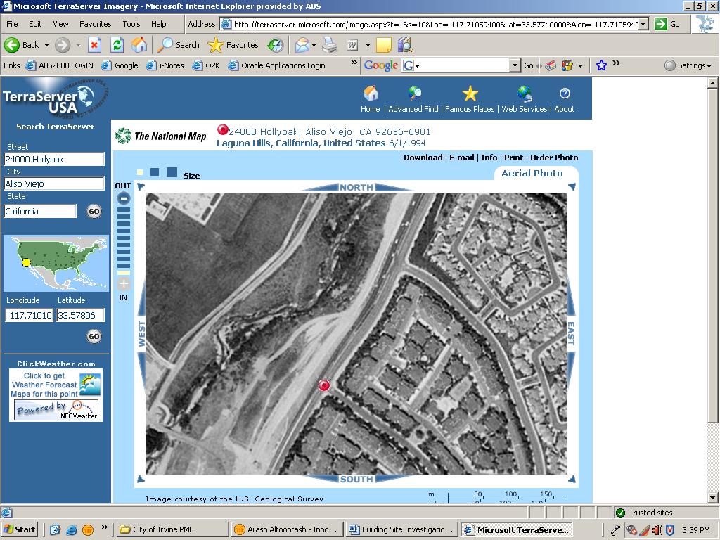
19 Site Data Site Location: Hollyoak Aliso Viejo, California Use Terraserver or other software to find: Latitude = Longitude = Site Class D (Per Soils Report or by default)
20
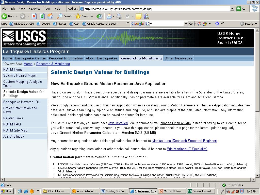
21 Ground Motion Using USGS ground motion JAVA application: S S = S 1 = MCE for Site Class D S MS =1.462 x 1.0 = S M1 =0.516 x 1.5 = DBE for Site Class D S DS =0.975 S D1 =0.516 < 0.75
22
23 Calculate Ss and S1

24 Calculate SM and SD
25 SDC A F vs. Site Class A-F Will cause confusion Site Class = Soil Type Default site class = D Seismic Design Category = SDC Defines material structure detailing requirements Limits permissible structural irregularities Replaces Zone-dependent detailing Traditional Zone 4 detailing similar to SDC D detailing
26 IBC defines an alternate method to determine Seismic Design Category Permitted to be used where S 1 is less than 0.75 Four conditions must ALL be met Rigid diaphragms Approx. Fundamental Period T a < 0.8T s Fundamental Period used to calculate story drift is less than T s Seismic Response Coeff. C s calculated using ASCE 7-05 Eqn Permits SDC to be determined using S D1 ONLY. Not likely within So.Cal. area
27 IBC Section contains other alternatives to ASCE Assumption of Flexible Diaphragm w/ wood structural panels or untopped steel decking permitted to be idealized as flexible Concrete or similar wood topping permitted only as nonstructural no greater than 1.5 inch thick Each line of resistance complies with allowable story drift Vertical LFRS elements limited to light-framed walls w/ wood panel or steel sheet shear panels (modifies IBC ) Parts of diaphragm in rotation limited to 25 ft & length/width of diaph.<1 for 1-story or 0.67 for 2+-story Use of OCBF s and OMF s is permitted in seismically isolated structures (w/conditions).
28 IBC Chapter 17, Structural Tests and Special Inspections Much more extensive than 1997 UBC 1997 UBC = 3 pages 2006 IBC = 16 pages!!! Provides useful tables separated by basic material types, defining verification and inspection requirements, with reference standards and IBC section references Requires statement of special inspections in construction documents SDC D+ Includes significant special inspection for non-structural components such as cladding, ceilings and storage racks Seismic Qualification of mechanical and electrical equipment. The registered design professional in responsible charge shall state the applicable seismic qualification requirements for designated seismic systems on the construction documents will require structural observation visits (with written statement) for SDC D+ or in high-wind regions for some Occupancy Categories, when height > 75 ft, or when building official requires.
29 Overview of ASCE 7-05 Seismic Provisions
30 ASCE 7-05 Seismic Provisions Table of Contents Ch. 11 Seismic Design Criteria Ch. 12 Seismic Design Requirements for Building Structures Ch 13 Seismic Design Requirements for Nonstructural Components Ch. 14 Material Specific Design & Detailing Requirements (not used w/ibc) Ch 15 Seismic Design Requirements for Non-Building Structures
31 ASCE 7 Table of Contents, Continued Ch. 16 and up contains rarely-used material Ch 16 Seismic Response History Procedures (i.e., time-history seismic analysis) Ch 17 Seismic Design Requirements for Seismically Isolated Structures (base isolation) Ch 18 Seismic Design Requirements for Structures with Damping Systems (such as viscous dampers) Ch 19 Soil Structure Interaction for Seismic Design (not commonly used) Ch 20 Site Classification Procedure for Seismic Design (definitions for soil types A-F)
32 ASCE 7 Table of Contents, Continued Ch 21 Site-Specific Ground Motion Procedures Ch 22 Seismic Ground Motion and Long Period Transition Maps (use instead.) Ch 23 Reference Documents App. 11A Quality Assurance Provisions (not used w/ibc) App. 11B Existing Building Provisions (replaced by IBC Ch. 34)
33 ASCE 7 Chapter Detail: Ch. 11 Design Criteria Ch. 11 contains List of Definitions Defines S S,S 1 etc. ground motion factors Defines site coefficients, F a, F v Defines Importance Factors, SDC s Presents a simplified procedure for SDC A Contains requirements for geotechnical investigation reports (depending on SDC)
34 Chapter Detail: Chapter 12 Seismic Design Requirements for Building Structures Most ordinary buildings will only use this chapter & Ch. 13 (nonstructural components) & material stds. R-Factor and Ht. Limit tables (3 pages!) Definitions of Irregularity types Rules for Horizontal & Vertical combinations of structural systems Definitions of Rigid & Flexible Diaphragms Introduces semi-rigid diaphragms Special Load Combinations incl. new redundancy-factor ELF & Response Spectrum Procedures More.
35 R-Factors Table is 3 pages long (vs. 1 in UBC) New Structural Systems Unbonded bracing systems Steel Plate Shear Walls Precast Concrete Systems Prestressed Masonry Shear Walls (not in SDC C-F)
36 New Precast Concrete Systems Special Precast Shear Wall Based on UCSD Research Intermediate Precast Shear Wall Traditional Tilt-Up Construction SDC D-F Limited to 40 ft. height, except one-story warehouses to 45 ft. Ordinary Precast Shear Wall Other types of precast Note!
37 Changes to R-Factors Bearing Wall Systems Light-framed walls w/ wood structural panels or steel sheets Light Framed walls, using flat strap bracing other shear panel types CIP Concrete Shear Walls Tilt-Up Concrete Shear Walls (Intermediate Precast) Masonry Shear Walls 97 UBC R ASCE 7-05 R
38 Changes to R-Factors, Cont d. Steel EBF Building Frame Systems Steel Ordinary Braced Frames Steel Special Concentric Braced Frames CIP Concrete Shear Walls Masonry Shear Walls 97 UBC R (160 ht. limit) ASCE 7-05 R 7, w/o MF 8, w/ MF 5 (35 ht. limit)
39 Changes to R-Factors, Cont d. Moment Frame Systems Special Steel MRF UBC: Ordinary Steel MRF Now: Intermediate Steel MRF Special Concrete MRF 97 UBC R ASCE 7-05 R (plus height & weight limits) 8 Cantilevered Column Elements 2.2 Varies 1 to 2.5
40 Diaphragm Flexibility Unless a diaphragm can be idealized as either flexible or rigid, the structural analysis shall explicitly include consideration of the stiffness of the diaphragm Flexible Diaphragm Condition. Diaphragms constructed of untopped steel decking or wood structural panels shall be permitted to be idealized as flexible in structures in which the vertical elements are steel braced frames, or concrete, masonry or steel shear walls. Diaphragms of wood structural panels or untopped steel decks in one and two-family residential buildings of lightframe construction shall also be permitted to be idealized as flexible Rigid Diaphragm Condition. Etc.
41 Irregularity Tables Three new irregularity types Extreme Torsional Irregularity Extreme Soft Story Irregularity Extreme Weak Story Irregularity Some changes in how irregularities are defined Intended to simplify calculation checks
42 Example Problem Vertical distribution of seismic lateral design forces
43 Seismic Design Criteria DBE for Site Class D S DS =0.975 S D1 =0.516 Four Story Residential Building Occupancy Category II (Table 1-1) Importance Factor I = 1.0 (Table ) Seismic Design Group: D (Table &2)
44 Building Information Roof H=54 ft 3rd H=41 ft 2nd H= 28 ft 1st H=15 ft Plan Elevation Seismic Participating Weight Level Seismic weight (kips) Height (ft) Roof W r rd W nd W st W Total W tot 1110
45 Design Coefficients Light Framed Walls Sheathed with Wood Panels R = 6.5 (Table bearing wall system) Ω 0 = 3 C d = 4 Approximate Period T = C h x t n C t = 0.02 (Table ) x = 0.75 h n = 54 ft T = 0.40 s (Eqn )
46 Equivalent Lateral Force Procedure Base Shear V = CS W = W (12.8-1) Where: C S = S R I DS = 0.15 (12.8-2) Not more than: Not less than: C S = C S SD 1 = 0.2 R T I 0.5S = 1 = 0.04 R I (12.8-3) for T<T L = 8 (s) (12.8-6)
47 Load Distribution V = 0.15xW = 166 kips (12.8-1) T 0.5 s : k = 1.0 (12.8.3) F C x vx = C = vx V k wxhx wh i k i Level W i h i W i h k i C vx F x Roof , rd , nd , st , Total 1,110 34,
48 Chapter Detail: Ch. 12 Continued & 11 - Diaphragms, chords, collectors, wall anchorage Drift & Bldg separations Foundation design Simplified Alternative Criteria Self Contained Must meet 12 conditions Intimidating for rigid diaphragm structures Not so bad for flexible diaphragm or flexible diaphragm permitted structures
49 12.14 Simplified Alternative Design 6½ -pages long (incl. tables & figures) Stands alone, other than Material Std. Requirements Separate Load Combinations, R-Factor Table, etc. Limited to 3 stories & less. Wood diaphragms permitted to be considered flexible No redundancy factor (but must meet 12 conditions in ) Force penalty for method 1.0 for single-story 1.1 for two story 1.2 for three story Separate R-Factor Table Only bearing wall & building frame systems permitted (no moment frames)
50 Example Problem Flexible Diaphragm Structure checks to use simplified alternative criteria
51 Condition checks for flexible diaphragm structures 1. Occupancy Category I or II only 2. Site Class not E or F (i.e., no soft-soil sites) 3. Structure not exceeding 3 stories 4. Only bearing wall or building frame systems (no Moment frames) 5. At least 2 lines of resistance in each direction 6. At least 1 line of resistance on each side of center of mass in each direction 7. Maximum diaphragm overhang = 20% depth 8. (n/a rigid diaphragm only) 9. Lines of resistance skewed no more than Simplified Method must be used for Both directions 11. In-Plane & Out-of-Plane irregularity types not permitted (Exception for light-frame structures) 12. Each story strength = at least 80% of story above
52 Redundancy Factor, ρ Still arbitrary Limited to SDC D-F. Separate ρ-factor is determined for each direction. ρ equal to either 1.0 or 1.3 nothing in between. ρ = 1 if loss or removal of any one element would not result in more than a 33 percent reduction in story strength, for any story resisting more than 35 percent of the base shear (see also Table ). Some specific calculations where ρ of 1 is permitted to be used (see section ). Otherwise, ρ = 1.3
53 12.12 Drift and Deformation Drift limits in ASCE 7-05 reduced for Occupancy Category III and IV structures Permissible drift a function of building type & stories, not period Permissible drift varies from to Note: ρ applied to drift limit of MRF in Design Category D-F! ( ) C Design story drift (Sec ) d δ δ xe x = I Minimum building separation ASCE distance sufficient to avoid damaging contact.. Versus UBC Δ MT = 2 ( Δ ) + ( Δ ) 2 M 1 M 2
54 Table Allowable Story Drift Structure Structures, other than masonry shear wall structures, 4 stories or less (etc.) Occupancy Category I or II III IV 0.025h sx 0.020h sx 0.015h sx Masonry cantilever shear wall structures 0.010h sx 0.010h sx 0.010h sx Other masonry shear wall structures 0.007h sx 0.007h sx 0.007h sx All other structures 0.020h sx 0.015h sx 0.010h sx Note: x 1.5 = x 1.5 = 0.015
55 Chapter Detail: Chapter 13 Seismic Design Requirements for Nonstructural Components 1997 UBC 2006 IBC F = 4. 0C I p a p W p F =1. 6S p DS I p W p F p apcai p h = R 1+ 3 p h x r W p F 0.4a ps = Rp I p W 1 + DS p p 2 z h 0.7C I W F 4C I a p p p a p W p 0.3S I W F 1. 6S DS p p p DS I p W p Note that = 2.5
56 Chapter Detail: Chapter 13 Continued Comparing R p values for selected nonstructural elements Interior Partitions URM other Exterior Wall Element Cantilever Parapet 1997 UBC (not defined) IBC Penthouses Summary: Although the F p z/h coefficient was reduced from 3 to 2, R p was also reduced, so that the net change is less.
57 Chapter Detail: Chapter 15 Nonbuilding Structures Far more extensive scope than ever before Tanks, Vessels, Racks, Boilers, Spheres New type of R-Factor Table Less Ductile Systems are permitted in high-seismicity areas, when lower R is used
58 Example from Ch. 15 Non-Building Structure R-Factor Table Structure Type R Ω o C d SDC C SDC D SDC E SDC F Ordinary Steel Concentrically Braced Frame 3 1 / / 4 NL NP With permitted height increase 2 1 / / 2 NL With unlimited height NL NL NL NL Compared to Ch. 12 Values for Buildings: OCBF 3 1 / / 4 NL NP
59 Other T L Maps Very long period 8 or 12 sec. Tank sloshing
60 Warning: ASCE Supplement 2 ASCE main committee is currently balloting a Supplement 2 change to seismic provisions. Would re-institute 2 nd minimum base shear equation. V=0.44 S DS IW ATC 63 preliminary finding that very tall buildings may need more min. lateral strength Bonus: would also result in compliance with Calif Field Act (3% min. x 1.4)
61 Warning: Structure separations Traditional minimum separation requirement is vague in IBC & ASCE 7. Vague limitation vs. UBC SRSS equation Existing UBC SRSS equation being submitted as correction for next cycle of ASCE 7-10.
62 ASCE 7-05 Errata Updated periodically and posted on Look in the Publications tab at the top of the page, under Errata Most recent posting May 3, pages total!!
63 End of Presentation Thank You for Staying Awake
Special Civil Engineer Examination Seismic Principles Test Plan
 SDR Workbook 2015 IBC Version Special Civil Engineer Examination Definition of Seismic Principles Seismic Principles is defined as the fundamental principles, tasks and knowledge s underlying those activities
Table 1. Detailed Comparison of Structural Provisions of 2000 IBC to 1997 NEHRP (continued)
") 1997 NEHRP 2000 IBC Section Provision Section Provision Comments 1 GENERAL PROVISIONS 1.1 PURPOSE No corresponding provision The lack of a purpose statement does not make IBC 1.2 SCOPE AND APPLICATION
1997 NEHRP 2000 IBC Section Provision Section Provision Comments 1 GENERAL PROVISIONS 1.1 PURPOSE No corresponding provision The lack of a purpose statement does not make IBC 1.2 SCOPE AND APPLICATION
Seismic Design of Precast Concrete Structures
 Seismic Design of Precast Concrete Structures S. K. Ghosh S. K. Ghosh Associates Inc. Palatine, IL and Aliso Viejo, CA Instructional Material Complementing FEMA 1052, Design Examples Diaphragms Analysis
Nonstructural Components
 Nonstructural Components Architectural, Mechanical and Electrical Components supported by or located within buildings or other structures. In 2003 NEHRP Recommended Provisions: Chapter 6 Architectural,
0306 SEISMIC LOADS GENERAL
 0306 SEISMIC LOADS 0306.1 GENERAL Every structure, and portion thereof, including nonstructural components such as architectural, mechanical, and electrical components, shall be designed and constructed
Lateral Design of Mid- Rise Wood Structures
 Lateral Design of Mid- Rise Wood Structures Presented by Ricky McLain, MS, PE, SE Technical Director WoodWorks Texas Workshops December, 2016 Insert picture of me graduating college Follow the load Following
OVERVIEW OF STRUCTURAL ENGINEERING STANDARDS
 OVERVIEW OF STRUCTURAL ENGINEERING STANDARDS The Basic Implementation of the 2003 NEHRP Recommended Provisions Overview of Standards 8b - 1 Scope Brief description of standards for design of basic building
Recent Advances in Seismic and Wind Design of Wood Structures &Historic Preservation Examples
 SEAoA 2015 Conference and Convention Recent Advances in Seismic and Wind Design of Wood Structures &Historic Preservation Examples Kelly Cobeen Wiss Janney Elstner Associates, Inc. Seminar Outline 1. NEHRP
Seismic Analysis Values with Spreadsheet
 PDHonline Course S232 (2 PDH) Seismic Analysis Values with Spreadsheet Instructor: John W. Andrew, PE 2012 PDH Online PDH Center 5272 Meadow Estates Drive Fairfax, VA 22030-6658 Phone & Fax: 703-988-0088
3.5 Tier 1 Analysis Overview Seismic Shear Forces
 Chapter 3.0 - Screening Phase (Tier ) 3.5 Tier Analysis 3.5. Overview Analyses performed as part of Tier of the Evaluation Process are limited to Quick Checks. Quick Checks shall be used to calculate the
Question 8 of 55. y 24' 45 kips. 30 kips. 39 kips. 15 kips x 14' 26 kips 14' 13 kips 14' 20' Practice Exam II 77
 Question 8 of 55 A concrete moment frame building assigned to SDC = D is shown in the Figure. Equivalent lateral force analysis procedure is used to obtain the seismic lateral loads, E h, as shown. Assume
Table 3. Detailed Comparison of Structural Provisions of IRC 2000 and 1997 NEHRP (Continued)
") 2000 IRC 1997 NEHRP Section Provision Section Provision Comments CHAPTER 3 BUILDING PLANNING R301 DESIGN CRITERIA R301.2.2 Seismic Provisions R301.2.2.1 Determination of Seismic Design Category R301.2.2.1.1
2000 IRC 1997 NEHRP Section Provision Section Provision Comments CHAPTER 3 BUILDING PLANNING R301 DESIGN CRITERIA R301.2.2 Seismic Provisions R301.2.2.1 Determination of Seismic Design Category R301.2.2.1.1
STRUCTURAL DESIGN REQUIREMENTS (SEISMIC PROVISIONS) FOR EXISTING BUILDING CONVERTED TO JOINT LIVING AND WORK QUARTERS
 FOR EXISTING BUILDING CONVERTED TO JOINT LIVING AND WORK QUARTERS") INFORMATION BULLETIN / PUBLIC - BUILDING CODE REFERENCE NO.: LABC Chapter 85 Effective: 01-01-2011 DOCUMENT NO.: P/BC 2011-110 Revised: Previously Issued As: P/BC 2002-110 STRUCTURAL DESIGN REQUIREMENTS
INFORMATION BULLETIN / PUBLIC - BUILDING CODE REFERENCE NO.: LABC Chapter 85 Effective: 01-01-2011 DOCUMENT NO.: P/BC 2011-110 Revised: Previously Issued As: P/BC 2002-110 STRUCTURAL DESIGN REQUIREMENTS
NONBUILDING STRUCTURE DESIGN
 12 NONBUILDING STRUCTURE DESIGN Harold O. Sprague Jr., P.E. Chapter 14 of the 2000 NEHRP Recommended Provisions and Commentary (hereafter, the Provisions and Commentary) is devoted to nonbuilding structures.
Individual Truss Marking Is it a Building Code Requirement?
 Introduction: Individual Truss Marking Is it a Building Code Requirement? Released April 1, 2010 On January 1, 2008, the 2007 edition of the California Building Code (CBC) 1 was adopted for use and replaced
School of Engineering and Applied Science Building Miami University, Oxford, OH Technical Assignment 3 December 3, 2007
 School of Engineering and Applied Science Building Miami University, Oxford, OH Technical Assignment 3 December 3, 2007 Jonathan Kirk AE 481W Senior Thesis The Pennsylvania State University Faculty Advisor:
CALIFORNIA BUILDING CODE
 FINAL STATEMENT OF REASONS FOR PROPOSED BUILDING STANDARDS OF THE DIVISION OF THE SATATE ARCHTECT REGARDING THE CALIFORNIA BUILDING CODE CALIFORNIA CODE OF REGULATIONS, TITLE 24, PART 2 The Administrative
Technical Report #3. Matthew R Peyton
 Technical Report #3 This Document is Technical Report #3 for 5th year senior thesis in the Architectural Engineering Departments at The Pennsylvania State University. In this report the existing reinforced
Clarifying Frequently Misunderstood Seismic Provisions
 Middle Tennessee Region of the Tennessee Structural Engineers Association Seminar: Clarifying Frequently Misunderstood Seismic Provisions By Emily Guglielmo, SE Martin/Martin, Inc. December 13, 2017 Fundamentals
Technical Assignment #3 November 15, 2004 Lateral System Analysis and Confirmation Design
 Executive Summary Technical Assignment #3 November 15, 2004 Lateral System Analysis and Confirmation Design The Food Science Building in State College, Pennsylvania is a four story above ground steel composite
r clarke 1 INTRODUCTION TO IBC SEISMIC FORCES
 r clarke 1 INTRODUCTION TO IBC SEISMIC FORCES 1.0 INTRODUCTION This presentation discusses seismic forces mainly from the perspective of the core requirements of the ICC s IBC 2009. The IBC 2009 caters
Remarks regarding FEMA 368 seismic analysis guidelines
 Earthquake Resistant Engineering Structures V 765 Remarks regarding FEMA 368 seismic analysis guidelines O. A. Mohamed Department of Civil and Environmental Engineering, University of Hartford, U.S.A.
Table 4. Detailed Comparison of Structural Provisions of 1997 NEHRP to 1997 UBC (continued)
") 1 GENERAL PROVISIONS SECTION 1626 GENERAL 1.1 PURPOSE Presents criteria for the design and construction of structures to resist earthquake ground motions. 1626.1 Purpose 1.2 SCOPE AND APPLICATION 1.2.1
1 GENERAL PROVISIONS SECTION 1626 GENERAL 1.1 PURPOSE Presents criteria for the design and construction of structures to resist earthquake ground motions. 1626.1 Purpose 1.2 SCOPE AND APPLICATION 1.2.1
Mandatory Wood Frame Soft-story Retrofit Program STRUCTURAL DESIGN GUIDELINES
 INFORMATION BULLETIN / PUBLIC - BUILDING CODE REFERENCE NO.: LAMC Division 93 Effective: 11/22/15 DOCUMENT NO.: P/BC 2014-137 Revised: 06/07/16 Previously Issued As: N/A Mandatory Wood Frame Soft-story
4.2 Tier 2 Analysis General Analysis Procedures for LSP & LDP
 4.2 Tier 2 Analysis 4.2.1 General Four analysis procedures are provided in this section: Linear Static Procedure (LSP), Linear Dynamic Procedure (LDP), Special Procedure, and Procedure for Nonstructural
See original reference (CODE) for full details
 for full details") Earthquake Engineering Course Notes Ahmed Elgamal Ahmed Elgamal 1997 Uniform Building Code (Seismic load brief introduction) See original reference (CODE) for full details From the section on Structural
Earthquake Engineering Course Notes Ahmed Elgamal Ahmed Elgamal 1997 Uniform Building Code (Seismic load brief introduction) See original reference (CODE) for full details From the section on Structural
CE 549 Building Design Project Spring Semester 2013
 CE 549 Building Design Project Spring Semester 2013 Instructor: Farzad Naeim, Ph.D., S.E., Esq. E-Mail: naeim@usc.edu Syllabus Overview: We will design a mid-rise office building using a team-approach
SESSION TU4C: The Steps Behind Building Resilience
 SESSION TU4C: The Steps Behind Building Resilience A 2020 NEHRP Effort: What Can You Expect on Major Changes on Seismic Provisions and US Seismic Value maps S.K. Ghosh, President, PhD, S.K. Ghosh Associates
North Shore at Canton Baltimore, MD Beau Menard Technical Report 1
 North Shore at Canton Baltimore, MD Beau Menard Technical Report 1 Structural Schneider 10/05/05 Structural Concepts Executive Summary North Shore at Canton is a 4 story town home and parking garage structure
3. Analysis Procedures
 3. Analysis Procedures 3.1 Scope This chapter sets forth requirements for analysis of buildings using the Systematic Rehabilitation Method. Section 3.2 specifies general analysis requirements for the mathematical
Significant Changes to AWC s Special Design Provisions for Wind and Seismic
 Significant Changes to AWC s Special Design Provisions for Wind and Seismic Michelle Kam-Biron, PE, SE, SECB Director of Education American Wood Council Copyright Materials This presentation is protected
Seismic Rehabilitation of Buildings. Anindya Dutta, Ph.D., S.E. Systematic vs. Simplified
 Seismic Rehabilitation of Buildings Anindya Dutta, Ph.D., S.E. Systematic vs. Simplified Systematic Rehabilitation Any Performance for any EQ Any Building Any deficiency Simplified Rehabilitation Life
Structural Design for Wind Loads: An Overview of Engineering Considerations for Wood
 Structural Design for Wind Loads: An Overview of Engineering Considerations for Wood Lori Koch, PE Manager, Educational Outreach American Wood Council Buildings Copyright Materials This presentation is
SEISMIC DESIGN REQUIREMENTS FOR REINFORCED CONCRETE BUILDINGS
 SEISMIC DESIGN REQUIREMENTS FOR REINFORCED CONCRETE BUILDINGS MODEL BUILDING CODES A model building code is a document containing standardized building requirements applicable throughout the United States.
2015 Special Design Provisions for Wind and Seismic Philip Line, P.E., John Buddy Showalter, P.E., Michelle Kam-Biron, P.E., S.E., Jason Smart, P.E.
 2015 Special Design Provisions for Wind and Seismic Philip Line, P.E., John Buddy Showalter, P.E., Michelle Kam-Biron, P.E., S.E., Jason Smart, P.E. The 2015 Edition of Special Design Provisions for Wind
Division IV EARTHQUAKE DESIGN
 1997 UNIFORM BUILDING CODE CHAP. 16, DIV. IV 1626 1627 Division IV EARTHQUAKE DESIGN SECTION 1626 GENERAL 1626.1 Purpose. The purpose of the earthquake provisions herein is primarily to safeguard against
CBC SECTION/TABLE NUMBER NEW -CHANGE COMMENTARY. X Flexible and Rigid definitions removed and found in ASCE 7-10
 2016 Chapter 16 Structural Design- Changes include new plan content requirements for Photovoltaic Panel Systems as well as guidance on how to determine the dead and live loads. For mid- and high-rise designs
Benchmarking Seismic Base Shear to Historical Practice
 Benchmarking Seismic Base Shear to Historical Practice Philip Line, P.E. Background Changes to seismic design procedures for wood construction often lead designers and structural standards committees to
IAPMO ES. Cover Sheet. Evaluation Criteria of. COLD-FORMED STEEL or WOOD FRAMED / STEEL-SHEATHED SHEAR WALLS
 IAPMO ES Cover Sheet Evaluation Criteria of COLD-FORMED STEEL or WOOD FRAMED / STEEL-SHEATHED SHEAR WALLS Posted for public commenting on 12/11/08 thru 1/14/09 Comments currently under review International
Simplified Building Schematic for Typical Floor (Levels 9 through 22):
:") Introduction to Structural System Simplified Building Schematic for Typical Floor (Levels 9 through 22): Key: - Tower Columns - Tower Shear Walls - Parking Garage Columns - Parking Garage Shear Walls Solid
Introduction to Structural System Simplified Building Schematic for Typical Floor (Levels 9 through 22): Key: - Tower Columns - Tower Shear Walls - Parking Garage Columns - Parking Garage Shear Walls Solid
Special Inspections for Wood Construction BCD710 Michelle Kam-Biron, PE, SE, SECB Senior Director, Education American Wood Council
 Special Inspections for Wood Construction BCD710 Michelle Kam-Biron, PE, SE, SECB Senior Director, Education American Wood Council Copyright Materials This presentation is protected by US and International
PEER/CSSC Tall Building Design Case Study Building #1. J. Andrew Fry John Hooper Ron Klemencic Magnusson Klemencic Associates
 PEER/CSSC Tall Building Design Case Study Building #1 J. Andrew Fry John Hooper Ron Klemencic Magnusson Klemencic Associates Building Information Located in Los Angeles 42-Story 410 ft Tall 108 ft X 107
John Jay College Expansion Project
 Technical Report #3 Michael Hopper Mike AE Consultant: Dr. Lepage [Type the company name] November 21 st, 2008 Technical Report #3 Table of Contents Executive Summary.3 Introduction.4 Existing Composite
CE 549 Building Design Project Spring Semester 2010
 CE 549 Building Design Project Spring Semester 2010 Instructor: Farzad Naeim, Ph.D., S.E., Esq. E-Mail: naeim@usc.edu Syllabus Overview: We will design a mid-rise office building using a team-approach
Response of TBI case study buildings
 Response of TBI case study buildings ANALYSIS OF STEEL BUILDING Pierson Jones & Farzin Zareian May 7 th, 2010 Introduction Three 40-story Building BRBF Systems building Structural and Earthquake Engineering
THE PLAZA AT PPL CENTER ALLENTOWN, PA
 : MOMENT FRAME COMPARISON Introduction Design Intent IBC 2000 and ASCE 7-98 recognizes steel frames designed with a response modification factor, R, less than or equal to three as structural steel systems
SEISMIC DESIGN GUIDELINES
 INTRODUCTION The purpose of these Seismic Design Guidelines is to provide additional information and clarification to Civil or Structural engineers in order to comply with Ordinance No. 18-O- 2767 for
Requirements and Solutions for Sunroom Lateral Design
 Requirements and Solutions for Sunroom Lateral Design Jay H. Crandell, P.E. ARES Consulting October 6, 2010 Technical Committee Meeting National Sunroom Association Outline Background on Sunroom Lateral
Seismic Design Criteria for Structures, Systems, and Components in Nuclear Facilities
 ASCE/SEI 43-05 American Society of Civil Engineers Seismic Design Criteria for Structures, Systems, and Components in Nuclear Facilities This document uses both the International System of Units (SI) and
Chinmoy Kolay Research Engineer
 Chinmoy Kolay Research Engineer Hands-on exercises 1. Numerical simulations using HybridFEM to experience some features of HybridFEM 2. Real-time hybrid simulation (RTHS) of a steel building 3. Soil-structure
Cross-Laminated Timber (CLT) in California: Guidelines, Testing and Recommendations
 in California: Guidelines, Testing and Recommendations") Cross-Laminated Timber (CLT) in California: Guidelines, Testing and Recommendations Presented by Scott Breneman, PhD, PE, SE Senior Technical Director Scott.Breneman@woodworks.org 1 The Wood Products Council
Cross-Laminated Timber (CLT) in California: Guidelines, Testing and Recommendations Presented by Scott Breneman, PhD, PE, SE Senior Technical Director Scott.Breneman@woodworks.org 1 The Wood Products Council
Two Stage Analysis Procedure: Wood on Podium Design
 Two Stage Analysis Procedure: Wood on Podium Design Part 1: Flexible Upper Portion Jared Cope, S.E. Two Stage Analysis Procedure: Wood on Podium Design 1 Two Stage Analysis: ASCE 7-10 Chapter 12 12.2.3.2
A. Are Plan Reviews Important? B. Statement of Special Inspections C. Deferred Submittals D. DFCM Requirements
 A. Are Plan Reviews Important? B. Statement of Special Inspections C. Deferred Submittals D. DFCM Requirements Is it okay to simply accept the engineer s stamp? Some key items to consider Life safety All
Alexis Pacella Structural Option Dr. Schneider Lexington II, Washington D.C. Technical Report #3 November 21,
 1 Executive Summary: Lateral System Analysis and Confirmation Design is an depth look at the lateral system of Lexington II and the loads of which it must carry. The structural system of Lexington II is
Design Example 2 Flexible Diaphragm Design
 Design Eample Fleible Diaphragm Design OVERVIEW This eample illustrates the design o a large leible diaphragm in a big-bo retail store subjected to lateral seismic loading. The roo structure consists o
CASE STUDY OF A 40 STORY BRBF BUILDING LOCATED IN LOS ANEGELES
 DESIGN INVESTIGATE REHABILITATE CASE STUDY OF A 40 STORY BRBF BUILDING LOCATED IN LOS ANEGELES Anindya Dutta, Ph.D., S.E. Ronald O. Hamburger, S.E., SECB www.sgh.com Background Study performed on behalf
MOUNTAIN STATE BLUE CROSS BLUE SHIELD HEADQUARTERS
 MOUNTAIN STATE BLUE CROSS BLUE SHIELD HEADQUARTERS PARKERSBURG, WEST VIRGINIA DOMINIC MANNO STRUCTURAL OPTION FACULTY CONSULTANT: DR. ANDRES LEPAGE Technical Report 3 11-21-08 TABLE OF CONTENTS TABLE OF
Update on the NEHRP Provisions: The Resource Document for Seismic Design
 Update on the NEHRP Provisions: The Resource Document for Seismic Design S. K. Ghosh, Ph.D., FPCI President S. K. Ghosh Associates, Inc. Palatine, Illinois This article discusses a number of major changes
SEAU 5 th Annual Education Conference 1. ASCE Concrete Provisions. Concrete Provisions. Concrete Strengths. Robert Pekelnicky, PE, SE
 ASCE 41-13 Concrete Provisions Robert Pekelnicky, PE, SE Principal, Degenkolb Engineers Chair, ASCE 41 Committee* *The view expressed represent those of the author, not the standard s committee as a whole.
WIND CODE EVALUATION. COLOMBIA Evaluation conducted by Guillermo Santana
 WIND CODE EVALUATION COLOMBIA Evaluation conducted by Guillermo Santana NAME OF DOCUMENT: Normas Colombianas de Diseño y Construcción Sismo Resistente (Colombian Standards for Seismic Resistant Design
Technical Report #3: Lateral System Analysis. Executive Summary
 ERIC MUELLER STRUCTURAL OPTION ADVISOR DR. LEPAGE AE 481W DECEMBER 19, 2006 555 12 TH STREET OAKLAND, CALIFORNIA Technical Report #3: Lateral System Analysis Executive Summary 555 12 th Street is a 21
Simplified Building Schematic for Typical Floor (Levels 9 through 22):
:") Introduction to Structural System Simplified Building Schematic for Typical Floor (Levels 9 through 22): Key: - Tower Columns - Tower Shear Walls - Parking Garage Columns - Parking Garage Shear Walls Solid
Introduction to Structural System Simplified Building Schematic for Typical Floor (Levels 9 through 22): Key: - Tower Columns - Tower Shear Walls - Parking Garage Columns - Parking Garage Shear Walls Solid
sixteen seismic design Earthquake Design Earthquake Design Earthquake Design dynamic vs. static loading hazard types hazard types: ground shaking
 APPLIED ARCHITECTURAL STRUCTURES: STRUCTURAL ANALYSIS AND SYSTEMS DR. ANNE NICHOLS FALL 2017 lecture sixteen dynamic vs. static loading amplification of static affect time duration acceleration & velocity
Trends in the Seismic Design Provisions of U.S. Building Codes
 Trends in the Seismic Design Provisions of U.S. Building Codes Seismic design provisions in building codes of the United States have undergone profound and farreaching changes in recent years. This paper
fifteen design for lateral loads Lateral Load Resistance Load Direction Lateral Load Resistance
 APPLIED ARCHITECTURAL STRUCTURES: STRUCTURAL ANALYSIS AND SYSTEMS DR. ANNE NICHOLS FALL 2013 lecture fifteen design for lateral loads Lateral Load Resistance stability important for any height basic mechanisms
CVEN 483. Structural System Overview
 CVEN 483 Structural System Overview Dr. J. Bracci Fall 2001 Semester Presentation Overview 1. Building system primary function 2. Types of load 3. Building materials 4. Structural members 5. Structural
Seismic Design & Qualification Methods An Interpretation of the IBC 2006 & ASCE 7 Code
 Seismic Design & Qualification Methods An Interpretation of the IBC 2006 & ASCE 7 Code Introduction Historically, the seismic design of mechanical equipment was primarily focused on the equipment supports,
La Jolla Commons Phase II Office Tower
 La Jolla Commons Phase II Office Tower San Diego, California Photos Provided Courtesy of HINES Alyssa Stangl Structural Option Faculty Advisor Dr. Hanagan Preliminary Vibrations and Layout Building Introduction
Seismic Design of Building Structures
 Seismic Design of Building Structures A Professional's Introduction to Earthquake Forces and Design Details Ninth Edition Michael R. Lindeburg, PE with Kurt M. McMullin, PE '.The Power to Pass www.ppi2pass.com
OVERALL STRUCTURAL SYSTEM
 EXECUTIVE SUMMARY The at the Pittsburgh International Airport, PA, is a 275,000 square foot multi-use building located directly adjacent to the airport s landside terminal. The building consists of an
Section 1 Introduction
 Section 1 Introduction Concern over the possibility of damaging earthquakes in the eastern United States developed through the 1970 s as a result of improved knowledge of both the history of eastern U.S.
fifteen design for lateral loads Lateral Load Resistance Load Direction Lateral Load Resistance
 APPLIED ARCHITECTURAL STRUCTURES: STRUCTURAL ANALYSIS AND SYSTEMS DR. ANNE NICHOLS SPRING 2017 lecture fifteen design for lateral loads Lateral Load Resistance stability important for any height basic
fifteen design for lateral loads Lateral Load Resistance Load Direction Lateral Load Resistance
 APPLIED ARCHITECTURAL STRUCTURES: STRUCTURAL ANALYSIS AND SYSTEMS DR. ANNE NICHOLS FALL 2014 lecture fifteen design for lateral loads Lateral Load Resistance stability important for any height basic mechanisms
Background and Purpose Acknowledgments. 1.1 Background The Architect s Role in Seismic Design Contents The Bottom Line 1-8
 FOREWORD AND ACKNOWLEDGMENTS Background and Purpose Acknowledgments i iii CHAPTER 1 INTRODUCTION Christopher Arnold 1.1 Background 1-1 1.2 The Architect s Role in Seismic Design 1-4 1.3 Contents 1-5 1.4
Technical Report 1. Residence Inn By Marriott. Structural Option September 29, Existing Conditions / Structural Concepts.
 Katie Ritter Advisor: Dr. Ali Memari Structural Option September 29, 2008 Technical Report 1 Existing Conditions / Structural Concepts Residence Inn By Marriott Norfolk, Virginia 1 P age TABLE OF CONTENTS
An Introduction to the 2015 NEHRP Recommended Seismic Provisions for New Buildings and Other Structures
 An Introduction to the 2015 NEHRP Recommended Seismic Provisions for New Buildings and Other Structures David R Bonneville 1 and Andrew M Shuck 2 ABSTRACT The 2015 NEHRP Recommended Seismic Provisions
Comparison of the Seismic Provisions of the 1997 Uniform Building Code to the 1997 NEHRP Recommended Provisions
 Comparison of the Seismic Provisions of the 1997 Uniform Building Code to the 1997 NEHRP Recommended Provisions S.K. Ghosh Associates, Inc. Northbrook, Illinois A report to: Building and Fire Research
2012 IBC. Volume 1 SEAOC STRUCTURAL/SEISMIC DESIGN MANUAL CODE APPLICATION EXAMPLES
 2012 IBC SEAOC STRUCTURAL/SEISMIC DESIGN MANUAL Volume 1 CODE APPLICATION EXAMPLES Copyright Copyright 2013 Structural Engineers Association of California. All rights reserved. This publication or any
TECHNICAL NOTE On Cold-Formed Steel Construction
 TECHNICAL NOTE On Cold-Formed Steel Construction 1201 15th Street, NW, Suite 320 Washington, DC 20005 (202) 785-2022 $5.00 Changes from the 1997 UBC to the 2006 IBC for Lateral Design with Cold-Formed
SEAU 5 th Annual Education Conference 1. Read the Standard! ASCE Analysis Provisions. (not just the tables and equations)
") ASCE 41-13 Robert Pekelnicky, PE, SE Principal, Degenkolb Engineers Chair, ASCE 41 Committee* *The view expressed represent those of the author, not the standard s committee as a whole. ASCE 41-13 Analysis
ASCE 41-13 Robert Pekelnicky, PE, SE Principal, Degenkolb Engineers Chair, ASCE 41 Committee* *The view expressed represent those of the author, not the standard s committee as a whole. ASCE 41-13 Analysis
Structural Technical Report 1 Structural Concepts / Existing Conditions
 Chris Shelow Structural Advisor: M. Kevin Parfitt Koshland Integrated Natural Science Center 10/05/05 AE 481W Structural Technical Report 1 Structural Concepts / Existing Conditions Executive Summary The
IS 1893 and IS Codal Changes
 IS 1893 and IS 13920 Codal Changes Reading between the lines Alpa Sheth IS 1893-2016 Changes In Estimation Of The Hazard a) Design spectra extended up to natural period up of 6 s; b) Same design response
Building Seismic Safety Council
 Notes on National Institute of Building Sciences Building Seismic Safety Council Burlingame, CA March 8, 2016 BSSC Annual Meeting and Colloquium Prepared by S. S. Szoke Annual Meeting Provisions Update
City of Berkeley Framework Guidelines for Soft, Weak or Open Front Building Retrofit Design
 Planning and Development Building & Safety Division City of Berkeley Framework Guidelines for Soft, Weak or Open Front Building Retrofit Design This document presents Guidelines for complying with Chapter
7. Seismic Design. 1) Read.
 Read.") 7. Seismic Design Lesson Objectives: 1) Describe code based seismic design in accordance with ASCE 7-16 and IBC 2012. 2) Compute mapped and design spectral accelerations. 3) Categorize and identify the
7. Seismic Design Lesson Objectives: 1) Describe code based seismic design in accordance with ASCE 7-16 and IBC 2012. 2) Compute mapped and design spectral accelerations. 3) Categorize and identify the
Chapter 2 QUALITY ASSURANCE
 Chapter 2 QUALITY ASSURANCE 2.1 GENERAL 2.1.1 Scope. This chapter provides minimum requirements for quality assurance for seismic-forceresisting systems and designated seismic systems. These requirements
[TECHNICAL REPORT 3] Lateral System Analysis
![[TECHNICAL REPORT 3] Lateral System Analysis](/thumbs/96/126531717.jpg "[TECHNICAL REPORT 3] Lateral System Analysis") Science Center Research Park 3711 Market St. The Pennsylvania State University Department of Architectural Engineering Senior Thesis 2009-2010 Prepared by: November 30, 2009 [TECHNICAL REPORT 3] Lateral
Science Center Research Park 3711 Market St. The Pennsylvania State University Department of Architectural Engineering Senior Thesis 2009-2010 Prepared by: November 30, 2009 [TECHNICAL REPORT 3] Lateral
Learning Objectives. Topics. Moment Frames: Design and Detailing per AISC 341 and 358. Topics. Lateral Analysis/Choosing your Code
 Topics Moment Frames: Design and Detailing per AISC 341 and 358 By Matthew J. Mester, PE, SE SidePlate Systems, Inc. SE University, June, 2017 www.learnwithseu.com 2 Learning Objectives Topics Identify
VOLUNTARY - EARTHQUAKE HAZARD REDUCTION IN EXISTING HILLSIDE BUILDINGS (Division 94 Added by Ord. No. 171,258, Eff. 8/30/96.)
") DIVISION 94 VOLUNTARY - EARTHQUAKE HAZARD REDUCTION IN EXISTING HILLSIDE BUILDINGS (Division 94 Added by Ord. No. 171,258, Eff. 8/30/96.) SEC. 91.9401. PURPOSE. (Amended by Ord. No. 172,592, Eff. 6/28/99,
DIVISION 94 VOLUNTARY - EARTHQUAKE HAZARD REDUCTION IN EXISTING HILLSIDE BUILDINGS (Division 94 Added by Ord. No. 171,258, Eff. 8/30/96.) SEC. 91.9401. PURPOSE. (Amended by Ord. No. 172,592, Eff. 6/28/99,
APPENDIX A - Seismic Terms, Tables and Figures:
 APPENDIX A - Seismic Terms, Tables and Figures: Seismic Design Force, (F p ) G-force that the unit must be able to withstand. This number is calculated using the factors described below. a S 0.4 P DS z
90% Design Submittal Structural Calculations Parking Garage CDRL
 NORTH METRO RAIL LINE PROJECT Thornton Crossroads at 104 th Avenue Station 90% Design Submittal Structural Calculations Parking Garage CDRL 03-037.11.06 June 2, 2017 Prepared by: Regional Rail Partners
Structural Technical Report 1 Structural Concepts/ Structural Existing Conditions Report
 Kelly M. Sadusky The Food Science Building Oct. 6, 2004 Professor Parfitt University Park, PA Structural Option Executive Summery: Structural Technical Report 1 Structural Concepts/ Structural Existing
EVALUATION OF COLLECTOR DESIGN FOR CONCRETE DIAPHRAGMS
 10NCEE Tenth U.S. National Conference on Earthquake Engineering Frontiers of Earthquake Engineering July 21-25, 2014 Anchorage, Alaska EVALUATION OF COLLECTOR DESIGN FOR CONCRETE DIAPHRAGMS J. S. LeGrue
SE APPRENTICE. Stephen Metz PE, LEED AP. Today s Speakers. Company Overview. Company Overview 10/13/2015. SE Apprentice. Who We Are.
 Today s Speakers Carrie Bremer, PE Schaefer Stephen Metz, PE SMBH, Inc. Today s Moderators SE APPRENTICE Lecture One Loads Lisa Willard, PE SE Solutions, LLC SE Apprentice Brian Quinn, PE SE Solutions,
FEMA 356 Life Safety Building Performance Evaluation & PML Analysis
 FEMA 356 Life Safety Building Performance Evaluation & PML Analysis For 2 Dinkelspiel Station Ln. Atherton, California September 24, 2009 Prepared for: Prepared by: Town of Atherton Crosby Group Office
A COMPARATIVE STUDY OF THE SEISMIC PROVISIONS BETWEEN IRAQI SEISMIC CODES 2014 AND 1997 FOR KURDISTAN REGION/IRAQ
 A COMPARATIVE STUDY OF THE SEISMIC PROVISIONS BETWEEN IRAQI SEISMIC CODES 214 AND 1997 FOR KURDISTAN REGION/IRAQ Bahman Omar Taha 1,Sarkawt Asaad Hasan 2 1&2 Erbil Polytechnic University 1 bahman.omar@epu.edu.krd,
Chapter 13 SEISMICALLY ISOLATED STRUCTURE DESIGN REQUIREMENTS
 Chapter 13 SEISMICALLY ISOLATE STRUCTURE ESIGN REQUIREMENTS 13.1 GENERAL 13.1.1 Scope. Every seismically isolated structure and every portion thereof shall be designed and constructed in accordance with
SEISMIC DESIGN OF STRUCTURE
 SEISMIC DESIGN OF STRUCTURE PART I TERMINOLOGY EXPLANATION Chapter 1 Earthquake Faults Epicenter Focal Depth Focus Focal Distance Epicenter Distance Tectonic Earthquake Volcanic Earthquake Collapse Earthquake
INTERNATIONAL ASSOCIATION OF PLUMBING AND MECHANICAL OFFICIALS UNIFORM EVALUATION SERVICES EVALUATION CRITERIA FOR
 INTERNATIONAL ASSOCIATION OF PLUMBING AND MECHANICAL OFFICIALS UNIFORM EVALUATION SERVICES EVALUATION CRITERIA FOR THE TESTING AND ANALYSIS OF STEEL SHEET SHEATHING FOR WOOD AND COLD FORMED STEEL LIGHT
Point Pleasant Apartments Point Pleasant, NJ Ryan P. Flynn Structural Option Faculty Consultant: Dr. Hanagan
 Point Pleasant Apartments Point Pleasant, NJ Ryan P. Flynn Structural Option Faculty Technical Report #3: Lateral System Analysis and Confirmation Design Table of Contents Introduction... 3 Executive Summary...