Bridging Your Innovations to Realities
|
|
|
- Jacob Hunter
- 6 years ago
- Views:
Transcription


1 Tutorial 2 Prestressed Concrete Bridge Bridging Your Innovations to Realities 1
2 Contents 2 1. Project Information 2. Definition of materials 3. Definition of Sections 4. Definition of Time dependent Materials 5. Creating the geometry 6. Boundary Conditions 7. Loads 8. Moving Load 9. Construction Stage Analysis 10. Results


3 1. Project Information 3 Perspective view 63m 16m

4 2. Definition of materials 4 In midas Civil materials can be added at any point in time as well as through different commands. However the most commonly used is : Properties -> Material Properties -> Material (tab)

5 2. Definition of materials Here, by pressing ADD a new dialog box pops up. Fill this in as shown below: 5

6 2. Definition of materials 6 After pressing apply this material will appear in the list for materials and you can add in the next one for the steel tendons as shown below: Material ID Name Type 1 C50/60 Concrete 2 Y_1670S7(15.2mm) Steel


7 3. Definition of Sections 7 Now that the materials are defined, the sections will be defined in the next step. This can be done in the Section tab by pressing Add and selecting the PSC tab. Here fill in the dialog box as shown below:


8 3. Definition of Sections 8 Similarly for the shallow section:


9 3. Definition of Sections 9 For the pier section go to the DB/User tab, fill in the data as shown below and press OK: Works Tree 3
 First")

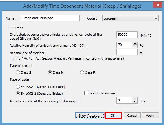
10 4. Definition of Time dependent Materials 10 Time dependent material effects can be defined from the Time Dependent Material tab: 1) First defining creep and shrinkage: 50,000 By clicking on show results, you can check the creep coefficient and shrinkage strain graphs as shown below:
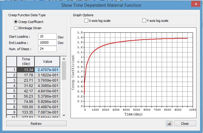
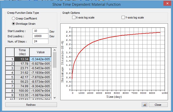
11 4. Definition of Time dependent Materials 11

12 4. Definition of Time dependent Materials 12 The variation of compressive strength will be defined as shown below :


13 4. Definition of Time dependent Materials 13 Now, in order to connect these properties to our material, a Material link will be generated as shown below:

14 4. Definition of Time dependent Materials 14 Goto Analysis > Construction Stage to check on Initial Tangent Displacement for Erected Structures


15 5. Creating the geometry 15 First create a node, this you can do from: Node/Element ->Create Nodes Fill in the pop up dialog box as shown below: In order to create the deck, this node will be extruded into line elements. Using the select single tool, select the node by drawing a box around it.


16 5. Creating the geometry 16 Next in order to obtain the line elements, the extrude feature shall be used from Node/Element -> Extrude: To obtain an appropriate mesh for the 63m deck this will be broken down into 3m long elements. In order to obtain this, fill in the dialog box as shown below: By pressing apply the following can be seen Zoom fit can be done by pressing icon :


 The Span has 21 elements and you can choose")
17 5. Creating the geometry 17 Now, to create the pier at mid point, select the middle element and divide this in two. You can select the middle element by ID from the Element Selection box. This can be done from : Node/Element -> Divide Then simply fill in the dialog box as shown below (it has these options by default so you only need to press apply) The Span has 21 elements and you can choose element number 11 to divide.


18 5. Creating the geometry 18 As a result this will change to: This node will be copied down by 6.5m (which is the depth of the diaphragm). First select the node using the select single option then go to: Node/Element -> Translate (within the node tab NOT elements)

19 5. Creating the geometry 19 And fill in the dialog box as shown below: Once the node is created in order to obtain the pier, this will be extruded by 16m using element lengths of 2 m.


20 5. Creating the geometry 20 Select the node, go to: Node/Element -> Extrude Elements and fill in the dialog box as shown below: Change section type to 3: Pier


21 5. Creating the geometry - Tapering of sections 21 In order to taper this bridge 2 tapered sections will be created. This can be done from Properties -> Section Properties -> Add -> Tapered Tab For the left side of the taper import the 'span' section for 'Size-i'

22 5. Creating the geometry - Tapering of sections 22 Scroll down and import 'diaphragm' for 'Size-j' then finally change the offset to Centre-Top by clicking on Change Offset... as shown below Similarly create taper right, however in this case 'Size-i' will be the Diaphragm section and 'Size-j' the Span section.


23 5. Creating the geometry - Tapering of sections 23 Once you have these two sections, turn on the element number and select elements 1 to 10 by putting this into the select elements window as shown below: For these selected elements just simply drag and drop Left taper from the works tree. This will taper your elements one by one.


24 5. Creating the geometry - Tapering of sections However to create a continuous tapering, select the elements 1 to 10, for which a tapered group will be created. Go to Properties -> Tapered Group 24 In the pop up dialog box just simply add in a name and press add as shown below: Once this is done the tapering will be finished

25 5. Creating the geometry - Tapering of sections 25 Now repeat the same procedure on the right hand side for elements 12 to 21 and naming the group Right taper. Once tapering is done on both sides this is what the bridge will look like: As we do not need the element numbers anymore, this can be deactivated


26 5. Creating the geometry - Groups 26 There are various groups in midas Civil these include: Structural, Boundary, Load and Tendon Groups To ease our work or for the purpose of construction stage analysis we need to create groups These groups can be found under the groups tab in the Tree menu. Right click on Structure Group and click on New...


27 5. Creating the geometry - Groups Add in Deck with specifying 1 to 4 suffixes: Similarly the Boundary and Load groups can be created so to obtain the following groups: 27 Then add in Pier as the last group without specifying any suffixes:


28 5. Creating the geometry - Groups Assigning elements to structure groups 28 Select elements 7to15 22, in other words the diaphragm and 4 segments on each side: For these elements simply drag and drop Deck 1, you will see these elements being assigned to this group :


29 5. Creating the geometry - Groups 29 Similarly the next two segments on each side will be added to Deck2 : The same procedure is repeated for the other four segments, they are added in 2 by 2 into Deck3 and Deck4.


30 5. Creating the geometry - Groups Finally the pier elements are added to the Pier structural group (to select these elements you can simply double click on the Pier section from the works tree and all the elements which have the Pier section assigned to them, will be selected) 30 Once the pier is added to the structure group, you have completed Structure Group: At this point you should have a model equivalent to: 1 - Groups Created


31 6. Boundary conditions 31 To provide stability for our structure and to represent the actual conditions in which this is, we need to provide boundary conditions. Supports For the definition of Side Support select the two end nodes of the deck. To make this selection easier, turn off the hidden view:

32 6. Boundary conditions 32 Select the two end nodes and go to: Boundary -> Define Supports and fill in the dialog box as shown Press apply and the following can be seen:


33 6. Boundary conditions 33 Similarly the Pier Support is defined. For this select the node at the bottom of the pier and fill in the boundary dialog box as shown below: Press apply and the following can be seen:


34 Links 6. Boundary conditions 34 To provide connectivity between the deck and the pier in the rigid zone a link needs to be created between the node at the top of the pier and mid point. For this go to Boundary -> Elastic Link, change the link type to Rigid Scroll down and click on '2 Nodes'. Now select the two nodes (top of pier and mid point of deck)

35 7. Loading 35 In midas Civil, loading works the following way: 1) Load cases are defined 2) Loads are assigned to these load cases Definition of load cases Go to Load -> Static Load Cases, here you can define all your load cases by defining their name, type and then pressing add:

36 7. Loading 36 In the same manner the following load cases are added in: Make sure all load types are Construction Stage Load At this point you should have a model equivalent to: 2 Boundaries and Load Cases


37 7. Loading 37 Self Weight Go to Load -> Self Weight and fill in the pop up dialog box: By pressing add, the self weight will appear in the window as shown below:


38 7. Loading 38 Surfacing For defining the surfacing load select the main deck and apply a Beam Element Load. For this go to: Load -> Element Beam Load as shown below: 1. Select all the elements for Deck 2. Load case/group name : Surfacing 3. Enter a value of -5 in the Global Z direction 4. Press apply

39 7. Loading 39 To clear the screen press initial view on the right side of the screen Form traveller and wet concrete load These two can be defined the same way by using nodal loads. Starting with the wet concrete loading, go to Load -> Nodal Loads


40 7. Loading 40 First select the node and then in the dialog box select the load case, load group name and fill in as shown below: By pressing 'apply' the Force and the Moment will be applied to the node. Using this procedure all wet concrete and form traveller loads can be applied. However these loads can be input into excel and applied to the model from there.

41 7. Loading 41 Here you can see the above loading after the dialog box was closed: The values for this can be displayed by right clicking on the load and press display: This can also be checked in a tabular format as well


42 7. Loading 42 Using this table, the loads, moments and groups can be defined for each node as shown in the Excel table below: First, delete the loading you have defined for node 7, and then by copying this table from Excel into the Nodal loads table the following can be seen:

43 7. Loading Looking in the works tree, the Form traveller loads and Wet concrete loads are all defined: 43 At this point you should have a model equivalent to: 3 - Loads - No Prestress Loads Added


44 7. Loading 44 Tendons and prestress When it comes to tendons, first the tendon property must be defined which can be done from: Here press Add in the pop up dialog box In the next dialog box, click on the 3 dots to define the tendon area and a small dialog box appears where you can specify the strand diameter and the number of strands:

45 7. Loading 45 Fill in the rest of the dialog box as shown below:


46 7. Loading 46 Creation of tendons To create the tendons go to: Load -> Temp/Prestress -> Tendon Profile The following dialog box appears, fill this in as shown. Also select the elements to which you want to assign the tendons or put this in the Assigned Elements field : By pressing OK, the tendon will be generated:

47 7. Loading 47 We will be creating 3 more tendons. Please create the tendons using the dialog box as shown: Make sure element 12to22 are assigned for tendon 3 and 4. Also, Make sure the Profile insertion point is changed to 22. Similarly tendon 4 will start from element 22 as well.

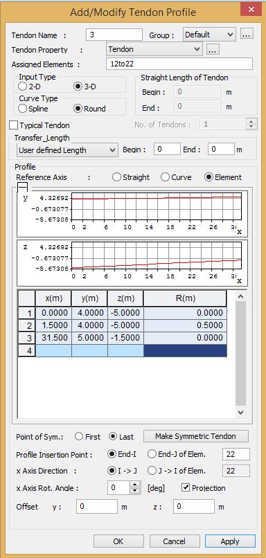
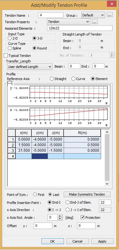
48 7. Loading 48

")
49 7. Loading 49 Once all four tendons are added in: Now all four will be copied down by 0.5m. For this, the copy option will be used within the tendon profile dialog box, first select all the tendon you want to copy (in this case all four of them) and then press Copy/Move. Here fill in the dialog box as shown right:

50 7. Loading 50 Once you press OK, all four tendons are copied down by 0.5m, the dialog box and the tendons appear as shown below:

51 7. Loading 51 Apply prestress: Go to Load -> Temp./Prestress -> Tendon prestress Change the units from the bottom right part of the screen. In this case it's beneficial changing into N and mm rather than using kn and m.


52 7. Loading Once the units are changed in the dialog box change the Load case and the load group names fill in the dialog box as shown below: The prestress added in will appear in the model and also will be added into the window above the Add button 52 At this point you should have a model equivalent to: 4 Loads Including Prestress Loads

53 8. Moving Load 53 Adding in Moving Loads in midas Civil is a 3 step procedure: 1) Define lanes 2) Add vehicles 3) Connect the lanes to the vehicles through moving load cases First specify the code to be used from Load -> Moving Loads-> Moving Load Code


54 8. Moving Load 54 Definition of lanes Go to: Load -> Moving Load -> Traffic Line Lanes -> Add Change the units back to m at the bottom right part of the screen. In midas Civil the definition of lanes happens with an eccentricity from a reference line

55 8. Moving Load 55 Following this, fill in the dialog box as shown: For the Selection by keep the option as 2 points, then click on the two ends of your bridge, this way the software will define the reference line from which your lane will be positioned at a distance defined in the eccentricity field.

56 8. Moving Load 56 Press Apply and you will see your lane being defined: When defining the next lane delete the information the software used to create the previous lane. For this simply click on No, and hit Delete

57 8. Moving Load 57 Similarly create lanes 2,3 and 4. The eccentricities for these are -1.5, 1.5 and 4.5m respectively. Once this is done, the lanes look as shown below:

58 8. Moving Load 58 Vehicle definition To define these go to Load -> Moving Load -> Vehicle -> Add Standard Here the adjustment factors can be changed for LM1.


59 8. Moving Load 59 By pressing apply the vehicle type can be changed, and LM3 can be defined: Looking at the works tree the following should be defined: Press ok and the second vehicle will be defined.

60 8. Moving Load 60 Moving Load cases Go to Load -> Moving Load -> Moving Load Case Here fill in the dialog box as shown below:


61 8. Moving Load 61 Add in another moving load case as shown below: By pressing OK The works tree will change as shown below: At this point you should have a model equivalent to: 5 Moving Loads
 To start defining these go to: Load -> Construction")

62 9. Construction Stage Analysis 62 As mentioned previously the groups will be used for the definition of the Construction Stages (CS) To start defining these go to: Load -> Construction stage -> Define C.S. -> Add In the dialog box that appears the duration will be defined as well as different Element, Boundary and Load groups will be activated. Fill in the dialog box as shown below. 28 days 100%

63 9. Construction Stage Analysis 63 With this the first construction stage is done. The following construction stages are described below in the table: Stage Duration Element Boundary Load CS2 10 Deck2 Activate:Wet Concrete2, Form Traveler2 Age 7 Deactivate: Wet Concrete1,Form Traveler1 CS3 10 Deck3 Activate:Wet Concrete3, Form Traveler3 Age 7 Deactivate: Wet Concrete2,Form Traveler2 CS4 10 Deck4 Activate:Wet Concrete4, Form Traveler4 Side Supports Age 7 Deactivate: Wet Concrete3,Form Traveler3 CS Activate: Surfacing Deactivate: Wet concrete4, Form Traveler4


64 9. Construction Stage Analysis 64 The construction stages can be check through the CS dropdown box in the modelling space: Once this is done, perform the analysis. When done the software will indicate the analysis was completed successfully in the message window: At this point you should have a model equivalent to: 6 Final Model


65 10. Results 65 All results can be checked in each construction stage for various load cases. Starting with the reactions, go to Results -> Reactions -> Reaction Forces/Moments Change to the CS which you would like to check and select the load case you want to check the results for. For these the values and the legend can be displayed : By pressing Apply the results can be checked


66 10. Results 66 Similarly Displacements can be checked from: Results -> Deformations -> Displacement Contour Bending Moments can be checked from: Results -> Forces -> Beam Diagrams Correction to be made

67 10. Results 67 Stress results can be checked from Results -> Stresses -> Beam Stresses (PSC)


68 10. Results 68 Tendon Stress Losses (Results -> Results Tables -> Tendon -> Tendon Loss) Here tendon stress losses can be checked in a tabular format: Correction to be made


69 10. Results 69 This can also be checked in a graphical format from the Tendon Loss Graph: Correction to be made


70 10. Results 70 Using the moving load tracer the software will generate the worst live load distribution for a particular position in the structure and a given effect. This can be checked only in the Post Construction stage. These moving load results can be checked using the Moving Load Tracer from : Results -> Moving Load -> Moving Load Tracer -> Beam Forces Moments

71 10. Results By clicking on Key Element the window turns green and you can simply click on the element of interest. By pressing Apply the influence lines and load distribution can be obtained 71
Release Webinar. Release Date : March Product Ver. : Civil 2016 (v2.1)
") Release Webinar Release Date : March. 2016 Product Ver. : (v2.1) DESIGN OF CIVIL STRUCTURES I n t e g r a t e d S o l u t i o n S y s t e m f o r B r i d g e a n d C i v i l E n g i n e e r i n g Enhancements
Release Webinar Release Date : March. 2016 Product Ver. : (v2.1) DESIGN OF CIVIL STRUCTURES I n t e g r a t e d S o l u t i o n S y s t e m f o r B r i d g e a n d C i v i l E n g i n e e r i n g Enhancements
BrD Superstructure Tutorial
 AASHTOWare BrD 6.8 BrD Superstructure Tutorial PS12 Prestressed Concrete I Beam Using BrD LRFD Engine BrD Superstructure Training PS12 - Prestressed Concrete I Beam Using BrD LRFD Engine 1'-9" 55'-6" Total
Prestress Superstructure Tutorial
 AASHTOWare BrDR 6.8.2 Prestress Superstructure Tutorial PS14 Prestressed Concrete I Beam Example PS14 - Prestressed Concrete I Beam Example This example details the data input of a prestressed concrete
Release Note DESIGN OF CIVIL STRUCTURES. Release Date : SEP. 1, 2015 Product Ver. : Civil 2016 (v1.1)
") Release Note Release Date : SEP. 1, 2015 Product Ver. : Civil 2016 (v1.1) DESIGN OF CIVIL STRUCTURES Integrated Solution System for Bridge and Civil Engineering Enhancements Analysis & Design 3 (1) UK
Release Note Release Date : SEP. 1, 2015 Product Ver. : Civil 2016 (v1.1) DESIGN OF CIVIL STRUCTURES Integrated Solution System for Bridge and Civil Engineering Enhancements Analysis & Design 3 (1) UK
AASHTOWare BrDR D FEM Analysis Tutorial. Curved Steel Multi-Span 3D Example
 AASHTOWare BrDR 6.8.2 3D FEM Analysis Tutorial Curved Steel Multi-Span 3D Example 3DFEM4 Curved Steel I Beam Using BrDR LRFD Engine This example details the data input of a curved composite steel plate
AASHTOWare Bridge Rating/DesignTraining. STL8 Single Span Steel 3D Example (BrR/BrD 6.4)
") AASHTOWare Bridge Rating/DesignTraining STL8 Single Span Steel 3D Example (BrR/BrD 6.4) Last Modified: 7/26/2012 STL8-1 AASHTOWare BrR/BrD 6.4 AASHTOWare Bridge Rating/DesignTraining STL8 Single Span Steel
AASHTOWare Bridge Rating/DesignTraining STL8 Single Span Steel 3D Example (BrR/BrD 6.4) Last Modified: 7/26/2012 STL8-1 AASHTOWare BrR/BrD 6.4 AASHTOWare Bridge Rating/DesignTraining STL8 Single Span Steel
AASHTOWare BrDR Prestressed Concrete Bridge Tutorial PS15 - Two Span PS Adjacent Box With Straight Strands
 AASHTOWare BrDR 6.8.2 Prestressed Concrete Bridge Tutorial PS15 - Two Span PS Adjacent Box With Straight Strands From the Bridge Explorer, create a new bridge and enter the following description data:
Civil 2011 (v2.1)release Note
release Note") Pre & Post-processing Civil 2011(v1.1)Release Note Civil 2011 (v2.1)release Note Integrated Solution System for Bridge and Civil Engineering 1 / 15 Pre & Post-processing Civil 2011(v1.1)Release Note Enhancements
Pre & Post-processing Civil 2011(v1.1)Release Note Civil 2011 (v2.1)release Note Integrated Solution System for Bridge and Civil Engineering 1 / 15 Pre & Post-processing Civil 2011(v1.1)Release Note Enhancements
AASHTOWare BrD 6.8. BrR and BrD Tutorial. PS7-3 Stem PS Bridge Example
 AASHTOWare BrD 6.8 BrR and BrD Tutorial PS7-3 Stem PS Bridge Example BrR and BrD Training PS7 3 Stem PS Bridge Example From the Bridge Explorer create a new bridge and enter the following description data.
Release Note. MIDAS Civil FX. midas Civil FX 2016
 Release Note MIDAS Civil FX midas Civil FX 2016 Release Note Release Date : March. 2016 Product Ver. : Civil 2016 (v2.1) DESIGN OF CIVIL STRUCTURES I n t e g r a t e d S o l u t i o n S y s t e m f o r
ADAPT-PT 2010 Tutorial Idealization of Design Strip in ADAPT-PT
 ADAPT-PT 2010 Tutorial Idealization of Design Strip in ADAPT-PT Update: April 2010 Copyright ADAPT Corporation all rights reserved ADAPT-PT 2010-Tutorial- 1 Main Toolbar Menu Bar View Toolbar Structure
1. Stress Analysis of a Cantilever Steel Beam
 . Stress Analysis of a Cantilever Steel Beam Applicable CivilFEM Product: All CivilFEM Products Level of Difficulty: Easy Interactive Time Required: 5-0 minutes Discipline: Structural Steel Analysis Type:
ADAPT-PTRC 2016 Getting Started Tutorial ADAPT-PT mode
 ADAPT-PTRC 2016 Getting Started Tutorial ADAPT-PT mode Update: August 2016 Copyright ADAPT Corporation all rights reserved ADAPT-PT/RC 2016-Tutorial- 1 This ADAPT-PTRC 2016 Getting Started Tutorial is
Release Note DESIGN OF CIVIL STRUCTURES. Release Date : July Product Ver. : Civil 2015 (v1.1)
") Release Note Release Date : July. 2014 Product Ver. : Civil 2015 (v1.1) DESIGN OF CIVIL STRUCTURES I n t e g r a t e d S o l u t i o n S y s t e m f o r B r i d g e a n d C i v i l E n g i n e e r i n
Release Note Release Date : July. 2014 Product Ver. : Civil 2015 (v1.1) DESIGN OF CIVIL STRUCTURES I n t e g r a t e d S o l u t i o n S y s t e m f o r B r i d g e a n d C i v i l E n g i n e e r i n
Advanced Application 7. Construction Stage Analysis of a Bridge Using a Composite Section
 Advanced Application 7 Construction Stage Analysis of a Bridge Using a Composite Section Civil CONTENTS Introduction 1 Cross Section 3 Materials 3 Loadings 3 Compose Construction Stages 4 Set Working Condition
Civil 2011 (v1.1) Release Note
 Release Note") New Module: GSD Civil 2011 (v1.1) Release Note Integrated Solution System for Bridge and Civil Engineering 1 / 35 New Module: GSD Enhancements New Module 3 1. General Section Designer Pre/Post Processing
New Module: GSD Civil 2011 (v1.1) Release Note Integrated Solution System for Bridge and Civil Engineering 1 / 35 New Module: GSD Enhancements New Module 3 1. General Section Designer Pre/Post Processing
ADAPT PT7 TUTORIAL FOR BEAM FRAME 1
 ADAPT PT7 TUTORIAL FOR BEAM FRAME 1 Technical Note Structural Concrete Software System TN189_PT7_tutorial_beam_frame 012705 1 BEAM FRAME The objective of this tutorial is to demonstrate the step-by-step
LARSA 2000/4th Dimension: Staged Construction Analysis
 LARSA 2000/4th Dimension: Staged Construction Analysis LARSA 2000/4th Dimension: Staged Construction Analysis for LARSA 2000 Finite Element Analysis and Design Software Larsa, Inc. Melville, New York,
AASHTOWare Bridge Rating/DesignTraining. STL9 Curved Steel 3D Example (BrR/BrD 6.5)
") AASHTOWare Bridge Rating/DesignTraining STL9 Curved Steel 3D Example (BrR/BrD 6.5) Last Modified: 7/31/2013 STL9-1 AASHTOWare BrR/BrD 6.5 Last Modified: 7/31/2013 STL9-2 AASHTOWare BrR/BrD 6.5 AASHTOWare
AASHTOWare Bridge Rating/DesignTraining STL9 Curved Steel 3D Example (BrR/BrD 6.5) Last Modified: 7/31/2013 STL9-1 AASHTOWare BrR/BrD 6.5 Last Modified: 7/31/2013 STL9-2 AASHTOWare BrR/BrD 6.5 AASHTOWare
ADAPT-PT 2012 GETTING STARTED GUIDE
 ADAPT-PT 2012 GETTING STARTED GUIDE Copyright ADAPT 2007, 2008,2012 all rights reserved support@adaptsoft.com www.adaptsoft.com ADAPT Corporation, Redwood City, California, USA, Tel: +1 (650) 306-2400
ADAPT-PT 2010 GETTING STARTED GUIDE
 ADAPT-PT 2010 GETTING STARTED GUIDE Copyright ADAPT 2007, 2008 all rights reserved support@adaptsoft.com www.adaptsoft.com ADAPT Corporation, Redwood City, California, USA, Tel: +1 (650) 306-2400 ADAPT
AASHTOWare BrD/BrR Prestress Tutorial 1 Simple Span Prestressed I Beam Example
 AASHTOWare BrD/BrR 6.8.3 Prestress Tutorial 1 Simple Span Prestressed I Beam Example Material Properties Beam Concrete: f'c = 6.5 ksi, f'ci = 5.5 ksi Deck Concrete: f'c = 4.5 ksi Prestressing Strand: 1/2"
Construction Stage Analysis Midas Civil. Presenter: Robert Salca technical support engineer, Midas UK
 Construction Stage Analysis Midas Civil Presenter: Robert Salca technical support engineer, Midas UK In order to make sure that the sound system is working well a poll will appear shortly on your screens.
MIDAS Training Series
 MIDAS midas Civil Title: All-In-One Super and Sub Structure Design NAME Edgar De Los Santos / MIDAS IT United States 2016 Substructure Session 1: 3D substructure analysis and design midas Civil Session
SETTLEMENTS DUE TO TUNNEL CONSTRUCTION
 5 SETTLEMENTS DUE TO TUNNEL CONSTRUCTION In this tutorial the construction of a shield tunnel in medium soft soil and the influence on a pile foundation is considered. A shield tunnel is constructed by
Prestressed Concrete Structure Tutorial
 AASHTOWare BrD/BrR 6.8 Prestressed Concrete Structure Tutorial PS5 Void Prestressed Box Beam Example BrR and BrD Training PS5 Void Prestressed Box Beam Example From the Bridge Explorer create a new bridge
Linear Static Analysis of a Stayed Steel Chimney
 Linear Static Analysis of a Stayed Steel Chimney Outline 1 Description 2 Finite Element Model 2.1 Units 2.2 Geometry Definition 2.3 Properties 2.4 Boundary Conditions 2.5 Loads 2.5.1 Load combinations
Stress distributions of PSC box girder bridge due to creep shrinkage effect
 Stress distributions of PSC box girder bridge due to creep shrinkage effect Baskoro Abdi Praja 1 1 Civil Eng. Department of Universitas Atma Jaya, 44 Babarsari, Yogyakarta Special Distric Indonesia Abstract.
CE 160 SAP 2000 Notes for 2D Problems. Element and Joint Drawing Tools Global Coordinates of Cursor Position Units in View Window
 CE 160 SAP 2000 Notes for 2D Problems SAP 2000 Main Screen Highlights Title of View Model Lock Zoom Controls Global Coordinate Plane of View Window Pull Down Menus Element and Joint Drawing Tools Global
Elevation. Typical Section
 PS1 - Simple Span Prestressed I Beam Example #4 stirrups @ 12" 120'-0" 6" 6" Elevation 1'-6" 51'-0" 48'-0" 1'-6" 8" Future Wearing Surface 2" thick, 150 pcf AASHTO-PCI BT-72 3'-0" 5 spaces @ 9'-0" = 45'-0"
AASHTOWare BrDR 6.8 Prestressed Concrete Design Tool Getting Started
 AASHTOWare BrDR 6.8 Prestressed Concrete Design Tool Getting Started Introduction AASHTOWare Bridge Design and Rating (BrDR) version 6.8 includes the first release of the Prestressed Concrete Design Tool
Analysis of a Severely Skewed Prestressed Concrete Beam Bridge
 Analysis of a Severely Skewed Prestressed Concrete Beam Bridge Gary L. Gardner, Jr., P.E. Bridge Technical Service Manager ms consultants, inc. August 19 th, 2015 MIDAS Special Elite Engineers Webinar
Load Rating of a Steel Composite Girder Bridge
 Load Rating of a Steel Composite Girder Bridge MIDAS 2016 Elite Engineers Webinar Series April 07, 2016 Luis J. Vila, Ph.D. Structural Engineer, GM2 Associates, Inc. Presentation Outline Introduction Modeling
ADAPT PT7 TUTORIAL FOR ONE-WAY SLAB 1
 Structural Concrete Software System TN187_PT7_tutorial_one_way_slab 012705 ADAPT PT7 TUTORIAL FOR ONE-WAY SLAB 1 1. ONE-WAY SLAB SUPPORTED ON BEAMS The objective of this tutorial is to demonstrate the
AASHTOWare BrDR 6.8 Steel Tutorial STL6 Two Span Plate Girder Example
 AASHTOWare BrDR 6.8 Steel Tutorial STL6 Two Span Plate Girder Example STL6 - Two Span Plate Girder Example (BrDR 6.5) 1'-6" 37'-0" 34'-0" 1'-6" 8 1/2" including 1/2" integral wearing surface FWS @ 25 psf
Creep Response of a Prestressed Concrete Beam under Sustained Load
 Creep Response of a Prestressed Concrete Beam under Sustained Load Outline 1 Description 2 Finite Element Model 2.1 Units 2.2 Geometry Definition 2.3 Boundary Constraints 2.4 Properties 2.4.1 Concrete
Release Note DESIGN OF CIVIL STRUCTURES. Release Date : Oct Product Ver. : Civil 2017 (v1.1)
") Release Note Release Date : Oct. 2016 Product Ver. : Civil 2017 (v1.1) DESIGN OF CIVIL STRUCTURES Integrated Solution System for Bridge and Civil Engineering Enhancements Analysis & Design 3 1) Assessment
Release Note Release Date : Oct. 2016 Product Ver. : Civil 2017 (v1.1) DESIGN OF CIVIL STRUCTURES Integrated Solution System for Bridge and Civil Engineering Enhancements Analysis & Design 3 1) Assessment
Seismic Analysis & Design of 10 Story RC Building
 Seismic Analysis & Design of 10 Story RC Building (Time History Analysis) Using ETABS (Metric Units) 0.3 yg 0.2 0.1 0 0 2 4 6 8 10 12-0.1-0.2-0.3 Table of Content Objective 5 Problem 5 Step by Step 11
midas Gen Advanced Webinar on Construction Stage Analysis with Special Emphasis on Column Shortening
 midas Gen Advanced Webinar on Construction Stage Analysis with Special Emphasis on Column Shortening Webinar Objective Construction Stage Analysis Column Shortening Procedure for Construction Stage Analysis
Tekla Structural Designer 2017
 Tekla Structural Designer 2017 Engineer s Handbooks (AS) March 2017 (5.0.0.7) 2017 Trimble Solutions Corporation part of Trimble Navigation Ltd. Table of Contents Wind Modeling Handbook... 1 Application
LARSA 4D Balanced Cantilever Problem
 LARSA 4D Balanced Cantilever Problem A manual for LARSA 4D Finite Element Analysis and Design Software Last Revised October 2016 Copyright (C) 2001-2016 LARSA, Inc. All rights reserved. Information in
CSiBridge Version Release Notes
 CSiBridge Version 20.0.0 Release Notes Copyright Computers and Structures, Inc., 2017 Notice Date: 2017-12-14 This file lists all changes made to CSiBridge since the previous version. Most changes do not
Release Note. Midas Civil 2017 (v1.1) MIDAS Civil FX
 MIDAS Civil FX") Release Note Midas Civil 2017 (v1.1) MIDAS Civil FX Release Note Release Date : Oct. 2016 Product Ver. : Civil 2017 (v1.1) DESIGN OF CIVIL STRUCTURES I n t e g r a t e d S o l u t i o n S y s t e m f o
Release Note Midas Civil 2017 (v1.1) MIDAS Civil FX Release Note Release Date : Oct. 2016 Product Ver. : Civil 2017 (v1.1) DESIGN OF CIVIL STRUCTURES I n t e g r a t e d S o l u t i o n S y s t e m f o
MWF Pro Truss. User Guide. Last Updated on November 9 th 2015
 MWF Pro Truss User Guide Last Updated on November 9 th 2015 Table of contents 1. Introduction... 3 1.1 Things to Know Before Starting... 3 1.1.1 Revit Model... 3 1.1.2 Roof... 3 2. Envelopes... 4 2.1 General
Bridging Your Innovations to Realities
 Contents 1. Objective 2. General Overview - midas Civil Software 3. Introduction Balanced Cantilever Bridge 4. Live Modelling Balanced Cantilever Bridge 2 1. Objective Objective 1.0 To model and analysis
Stay Tuned! Practical Cable Stayed Bridge Design
 midas Civil Stay Tuned! Practical Cable Stayed Bridge Design 2017 Francesco Incelli I. Introduction II. Modeling of the cable-stayed bridge a. Bridge wizard b. Girder Cross Section III. Nonlinear Effect
AASHTOWare BrR 6.8 Steel Tutorial Steel Plate Girder Using LRFR Engine
 AASHTOWare BrR 6.8 Steel Tutorial Steel Plate Girder Using LRFR Engine STL6 - Two Span Plate Girder Example 1'-6" 37'-0" 34'-0" 1'-6" 8 1/2" including 1/2" integral wearing surface FWS @ 25 psf 3'-6" 3
2018 InfoGraph GmbH, Aachen, Germany. All rights reserved.
 The description of program functions within this documentation should not be considered a warranty of product features. All warranty and liability claims arising from the use of this documentation are
AASHTOWare BrR 6.8. Truss Tutorial. T5 - Truss Enhancements
 AASHTOWare BrR 6.8 Truss Tutorial T5 - Truss Enhancements BrR Training T5 Truss Enhancements Topics Covered Longitudinal Truss - Counters, Member eccentricity, Suspended span and Deck-through configuration
Moving Load Analysis for Bridge Structures
 Moving Load Analysis for Bridge Structures The moving load analysis function in MIDAS/Civil is used to statically analyze and design bridge structures for vehicle moving loads. Important features are included
MDOT Camelback Bridge Example
 MDOT Camelback Bridge Example AASHTOWare Bridge Rating 6.4.1 July 8, 2013 Contents MDOT Camelback Bridge Example AASHTOWare Bridge Rating 6.4.1... 1 Background... 2 Assumptions/Limitations... 2 General
AASHTOWare BrR/BrD 6.8 Reinforced Concrete Structure Tutorial RC5 Schedule Based Tee Example
 AASHTOWare BrR/BrD 6.8 Reinforced Concrete Structure Tutorial RC5 Schedule Based Tee Example BrR and BrD Training RC5 Schedule Based Tee Example Topics Covered Reinforced concrete schedule based tee input
ADAPT Floor Pro 2009/2010 Tutorial Export Design Strip to ADAPT PT or ADAPT RC
 ADAPT Floor Pro 2009/2010 Tutorial Export Design Strip to ADAPT PT or ADAPT RC Update: May 2010 Copyright ADAPT Corporation all rights reserved ADAPT PT 2010/RC 2010 to ADAPT Floor Pro 2009/2010 Strip
Code Checks of Prestressed Structures in SCIA ESA PT
 Code Checks of Prestressed Structures in SCIA ESA PT Table Of Contents Prestressed concrete... 5 Checks of prestressed concrete... 5 Crack control... 5 Performing crack control... 6 Checking of limit
Nonlinear Finite Element Analysis of Composite Cantilever Beam with External Prestressing
 Nonlinear Finite Element Analysis of Composite Cantilever Beam with External Prestressing R. I. Liban, N. Tayşi 1 Abstract This paper deals with a nonlinear finite element analysis to examine the behavior
ANSYS Customization for Bridges and Prestressed Concrete Structures Analysis and Design
 ANSYS Customization for Bridges and Prestressed Concrete Structures Analysis and Design Javier Aparicio Ingeciber, S.A. Isabella Maia Ingeciber, S.A. Eduardo Salete Ingeciber, S.A. Abstract This paper
ADAPT-Floor Pro 2009 Tutorial Export Design Strip to ADAPT-PT or ADAPT-RC
 ADAPT-Floor Pro 2009 Tutorial Export Design Strip to ADAPT-PT or ADAPT-RC Update: May 2010 Copyright ADAPT Corporation all rights reserved 1 EXPORT DESIGN STRIP FROM ADAPT-FLOOR PRO TO ADAPT-PT OR ADAPT-RC
AASHTOWare BrDR 6.8 Feature Tutorial 2016 BrDR User Requested Enhancements
 AASHTOWare BrDR 6.8 Feature Tutorial 2016 BrDR User Requested Enhancements Topics Covered Reinforced concrete box culvert enhancements o Culvert Wizard for creating Culverts, Culvert Structure Alternatives
Finite Element Simulation of Cantilever Construction Structure
 Finite Element Simulation of Cantilever Construction Structure Baofeng Pan 1, Gang Li 2 Abstract In order to realize the control ultimate goal, it is necessary to predict and control the deformation and
2. Outline of the bridge 3-span continuous deck extradosed bridge Bridge length
 Construction of Extradosed Bridge in the Government Financed Section EUI-NAM PARK, PM, Incheon Bridge Section 5, Doosan Construction & Engineering corporation KYUNG-KUK JUNG, GM, Incheon Bridge Section
Extreme Loading for Structures Version 3.1
 Extreme Loading for Structures Version 3.1 Corrosion Effects Option April 2010 1. Introduction Corrosion of gusset plates was identified as one of the main causes for failure in the catastrophic collapse
The content for this class has been provided by the following PB employees: With assistance from: Martine Klein, P.E. Narration by Greg Metzger, PB
 1 The content for this class has been provided by the following PB employees: With assistance from: Martine Klein, P.E. Narration by Greg Metzger, PB University If you have any questions about the content
Bridging Your Innovations to Realities
 Contents: I. Introduction II. Modeling of the cable-stayed bridge a. Bridge wizard b. Stiffening girder III. Initial Cable Forces a. The Unknown Load Factor function - Constraints - Influence matrix IV.
Release Note DESIGN OF CIVIL STRUCTURES. Release Date : Aug. 13, 2013 Product Ver. : Civil 2013 v3.1
 Release Note Release Date : Aug. 13, 2013 Product Ver. : Civil 2013 v3.1 DESIGN OF CIVIL STRUCTURES Integrated Solution System for Bridge and Civil Engineering Enhancements 1. Improvements in Pushover
ADAPT PT7 TUTORIAL FOR A NON-PRISMATIC SLAB 1
 Structural Concrete Software System ADAPT PT7 TUTORIAL FOR A NON-PRISMATIC SLAB 1 TN190_PT7_non_prismatic_slab 012705 1. NON-PRISMATIC (SEGMENTAL) COLUMN-SUPPORTED SLAB The objective of this tutorial is
May 26 th, MWF Truss. User Guide
 May 26 th, 2017 MWF Truss User Guide 1 1. Introduction... 3 1.1 Things to Know Before Starting... 3 1.1.1 Revit Model... 3 1.1.2 Roof... 3 1.1.3 Adding Families... 4 2. Envelopes... 5 2.1 General Envelope
Construction stages, prestressing and TDA in SCIA ESA PT
 Construction stages, prestressing and TDA in SCIA ESA PT Table Of Contents Construction stages, prestressing, TDA... 5 Introduction... 5 Brief introduction to construction stages... 5 Brief introduction
ATENA Program Documentation Part 4-8
 Červenka Consulting s.r.o. Na Hrebenkach 55 150 00 Prague Czech Republic Phone: +420 220 610 018 E-mail: cervenka@cervenka.cz Web: http://www.cervenka.cz ATENA Program Documentation Part 4-8 ATENA Science
midas Gen Advanced Webinar Column Shortening for High-rise Building
 midas Gen midas Gen Advanced Webinar for High-rise Building for High-rise Building Introduction in Project Applications Procedure for Construction Stage Analysis Useful features for Construction Stage
STRUCTURAL CONCRETE SOFTWARE ADAPT-ABI. Examples
 990727 STRUCTURAL CONCRETE SOFTWARE ADAPT-ABI Examples This supplemental reference manual is made available to users of ADAPT-ABI 2012 to help them understand the underlying modeling and analysis capabilities
V B D S. Visual Bridge Design System. S. Q. Wang, Ph.D., P.E. and Chung C. Fu, Ph.D., P.E. Distributed By
 V B D S Visual Bridge Design System By S. Q. Wang, Ph.D., P.E. and Chung C. Fu, Ph.D., P.E. Distributed By The Bridge Engineering Software and Technology (BEST) Center University of Maryland, College Park,
A REAL CASE STUDY ABOUT EVALUATION OF THE EXISTING SITUATION OF A POST TENSIONED SINGLE SPAN BOX GIRDER BRIDGE
 A REAL CASE STUDY ABOUT EVALUATION OF THE EXISTING SITUATION OF A POST TENSIONED SINGLE SPAN BOX GIRDER BRIDGE Ali Günalp Görgülü, Sema Melek Kasapgil, Kamil Ergüner Mega Mühendislik Müh. A.S, Ankara,Türkiye
Post-tensioned prestressed concrete bridge - assignment
 Post-tensioned prestressed concrete bridge - assignment Design a post-tensioned prestressed concrete bridge of a three-span arrangement. The construction is prestressed at the age of 7 days and put into
4 th Example Masonry Structure Analysis and Design
 4 th Example Masonry Structure Analysis and Design 2 Contents OVERVIEW defined. Error! Bookmark not INTRODUCTION 5 THE NEW ENVIRONMENT 5 GENERAL DESCRIPTION 7 A. Geometry 7 B. Materials 7 C. Regulations
FAQ. for Midas Gen Link, Preference and Drawings. Design + Solution for Structural Member Design with Drawing & Report
 F Design + for Midas Gen Link, Preference and Drawings Solution for Structural Member Design with Drawing & Report midas Design + Contents F 01. midas Gen Link 3 How to link with midas Gen? Member forces
ENGR102 Engineering Design Lab II Winter 2014
 ENGR 102 Engineering Design Lab II Bridge Module Week 3 Introduction to Visual Analysis Introduction For the remainder of this module, you will use Visual Analysis to determine the member forces when loading
CE Advanced Structural Analysis. Lab 3 SAP2000 Beam and Frame Structures
 Department of Civil & Geological Engineering COLLEGE OF ENGINEERING CE 463.3 Advanced Structural Analysis Lab 3 SAP2000 Beam and Frame Structures February 06 th, 2013 T.A: Ouafi Saha Professor: M. Boulfiza
ASSIGNMENT 1 ANALYSIS OF PRESTRESS AND BENDING STRESS BFS 40303
 Instruction : Answer all question ASSIGNMENT 1 ANALYSIS OF PRESTRESS AND BENDING STRESS BFS 40303 1. A rectangular concrete beam, 100 mm wide by 250 mm deep, spanning over 8 m is prestressed by a straight
ULTIMATE LOAD-CARRYING CAPACITY OF SELF-ANCHORED CONCRETE SUSPENSION BRIDGE
 ULTIMATE LOAD-CARRYING CAPACITY OF SELF-ANCHORED CONCRETE SUSPENSION BRIDGE Meng Jiang*, University of Technology Dalian, P. R. China Wenliang Qiu, University of Technology Dalian, P. R. China Lihua Han,
Rail Track Analysis Wizard
 Rail Track Analysis Wizard M I D A S I T 111-1 01 Rail Track Analysis Wizard The Rail Track Analysis Wizard builds a model that is used for checking the additional stresses and the displacements due to
ETABS 2016 Tutorial: Trusses
 ETABS 2016 Tutorial: Trusses Below is a tutorial that was organized for educational purposes at Christian Brothers University only. The procedure of analysis in ETABS 2016 is similar to that of ETABS v9.
Nonlinear Redundancy Analysis of Multi-Cell Pre-stressed Concrete Box-Girder Bridge
 Nonlinear Redundancy Analysis of Multi-Cell Pre-stressed Concrete Box-Girder Bridge Analysis Report Bala Sivakumar PE O. Murat Hamutcuoglu Ph.D. HNTB Corporation Dr. Michel Ghosn Ph.D. The City College
FAQ. External Prestressing. Professional Engineering Software. Frequently Asked Questions and Solutions for RM2004
 Professional Engineering Software Frequently Asked Questions and Solutions for RM2004 Technische Datenverarbeitung Dorian Janjic & Partner GmbH Papers included in the series are detailed descriptions for
Influence of Depth in Single Cell & Twin Cell Box Girder
 Influence of Depth in Single Cell & Twin Cell Box Girder V. Raja Srinivasa Reddy 1, P. Veerabhadra Rao 2 P.G student, Dept. of Civil Engineering, GVP College of Engineering (A), Visakhapatnam, India 1
STRESS-RIBBON BRIDGES STIFFENED BY ARCHES OR CABLES
 2nd Int. PhD Symposium in Civil Engineering 1998 Budapest STRESS-RIBBON BRIDGES STIFFENED BY ARCHES OR CABLES Tomas Kulhavy Technical University of Brno, Department of Concrete and Masonry Structures Udolni
ADAPT-BUILDER : General Analysis/Design Options
 ADAPT-BUILDER : General Analysis/Design Options Quick Reference Guide Updated November 2017 Copyright All rights reserved 2017 1 2 3 4 5 6 7 8 9 General analysis/design options: 1. Both prestressed and
Bond-slip of Post-tensioned Reinforcement in 2D elements
 Y X Bond-slip of Post-tensioned Reinforcement in 2D elements ANALYS keywords: nonlin phase physic CLASS keywords: large CONSTR keywords: suppor tying ELEMEN keywords: bar bondsl cable cl6tr cq16m cq22if
T4 Floor Truss Example. AASHTOWare BrR 6.8 Truss Tutorial
 AASHTOWare BrR 6.8 Truss Tutorial T4 Floor Truss Example BrR Training T4 Floor Truss Example Topics Covered Floor and truss system/line superstructure definitions overview Floor truss description Analysis
Shrinkage Effects on a Concrete Slab on Ground
 Shrinkage Effects on a Concrete Slab on Ground Outline 1 Description 2 Finite Element Model 2.1 Units 2.2 Geometry Definition 2.3 Properties 2.3.1 Concrete slab 2.3.2 Grid reinforcement 2.3.3 Soil interface
Design of Izmir Bay Crossing Bridge
 Design of Izmir Bay Crossing Bridge Burak Kurtman Dpt. Manager of Bridge Group, Yüksel Project International, Ankara, Turkey Tel: +90 (312) 4957000 E-mail: bkurtman@yukselproje.com.tr Abstract The Izmir
Step. Stability Analysis of Reinforced Earth Retaining Walls - LEM. Slope Module Tutorial
 Stability Analysis of Reinforced Earth Retaining Walls - LEM Slope Slope Module Tutorial 00 Stability Analysis of Reinforced Earth Retaining Walls - LEM Overview Limit Equilibrium Method (LEM) is used
Design and Rating of Steel Bridges
 2014 Bentley Systems, Incorporated Parametric and Integrated Bridge Design LEAP Bridge Steel Steve Willoughby Design and Rating of Steel Bridges 2 WWW.BENTLEY.COM 2014 Bentley Systems, Incorporated 1 Discussion
Modeling and Design of Bridge Super Structure and Sub Structure
 Topic 3 Day 2 Modeling and Design of Bridge Super Structure and Sub Structure Naveed Anwar 1. Over view of Bridge Design Process and Bridge Types 2. Advances and recent trends in Modeling and Analysis
Monitoring of External Prestressing Tendons Construction Process of Jiamusi Highway Prestressed Concrete Bridge during Strengthening in China
 Advanced Materials Research Vols. -7 () pp 87-879 Online available since /Dec/ at www.scientific.net () Trans Tech Publications, Switzerland doi:.8/www.scientific.net/amr.-7.87 Monitoring of External Prestressing
LUSAS Version 16. simplify collaborate design. Summary of new features and enhancements
 LUSAS Version 16 simplify collaborate design Summary of new features and enhancements LUSAS Version 16 Version 16.0 of LUSAS is a major software release that sees the introduction of steel frame design
Hyperstatic (Secondary) Actions In Prestressing and Their Computation
 Actions In Prestressing and Their Computation") 5.5 Hyperstatic (Secondary) Actions In Prestressing and Their Computation Bijan O Aalami 1 SYNOPSIS This Technical Note describes the definition, computation, and the significance of hyperstatic (secondary)
5.5 Hyperstatic (Secondary) Actions In Prestressing and Their Computation Bijan O Aalami 1 SYNOPSIS This Technical Note describes the definition, computation, and the significance of hyperstatic (secondary)
DESIGN & ANALYSIS OF RECTANGULAR RCC OVERHEAD WATER TANK
 DESIGN & ANALYSIS OF RECTANGULAR RCC OVERHEAD WATER TANK Data: Size of water Tank 4.0m x4.0m x2.0m Height of water tank from GL =8.0m Water tank wall thickness =180mm Size of column = 300 x 300 mm Bracing
SECTION 1 INTRODUCTION TO POST-TENSIONED CONCRETE DEVELOPED BY THE PTI EDC-130 EDUCATION COMMITTEE
 SECTION 1 INTRODUCTION TO POST-TENSIONED CONCRETE DEVELOPED BY THE PTI EDC-130 EDUCATION COMMITTEE NOTE: MOMENT DIAGRAM CONVENTION In PT design, it is preferable to draw moment diagrams to the tensile
CSiBridge Version Release Notes
 CSiBridge Version 20.1.0 Release Notes Copyright Computers and Structures, Inc., 2018 Notice Date: 2018-05-03 This file lists all changes made to CSiBridge since the previous version. Most changes do not
User Guide. for Eurocode Modules. Design+ Interface General Column Design Combined Wall Design Strip Foundation Design Design Parameters
 Solution for Structural Member Design with Drawing & Report midas Design + User Guide for Eurocode Modules Design+ Interface General Column Design Combined Wall Design Strip Foundation Design Design Parameters