Scaffold Instruction Manual
|
|
|
- Brittany Mason
- 6 years ago
- Views:
Transcription
1 Scaffold Instruction Manual This booklet contains information on how to erect, stabilize, dismantle and maintain your MultiScaff aluminium scaffolding. Manufactured by: August 2014
2 Index Page Number Safety Rules.. 2 Safety Directive Transportation.. 3 Storage. 3 Maximum Height 4 Erection of MultiScaf Mobile Scaffolding 5 Doorway Towers 6 Base Pack Assembly Instructions... 6 Handrail Pack Assembly Instructions 7 Connector Pack Assembly Instructions. 9 Standard Towers 9 Adding Extra Working Platforms 12 Ladder Installation Options 14 Toeboard Installation. 14 Outrigger Props. 15 Extra Wide Base Towers. 16 Static Walk-Thru Face Scaffolds. 18 Scaffolding Checklist. 21 The Intended Duty of the Scaffold Including its Maximum Platform Capacity 22 A General Guide to Safe Scaffolding Work Practices. 23 Maintenance Schedule Contact Details.. 25 Page 1
3 Safety Rules Work Faster And Safer By Following These Seven Essential Rules ules: 1. Never move scaffold when someone is on it. 2. Always re-level the scaffold after moving. 3. Always apply brakes on all four wheels before using the scaffold. 4. Make sure the scaffold is used on a firm surface, which will support the loaded scaffold weight. 5. Do not overload the scaffold weight limits are clearly shown on the side of the platforms. 6. Do not allow scaffold to come within 4 metres of overhead power lines (some higher voltage lines may require greater distance). 7. Make sure the area of operations is free of floor penetrations and other hazards. Page 2

4 Attention:- Safety Directive Attention all MultiScaff Aluminium Scaffolding Users: Please note that when horizontals are clipped to standards (vertical member) they are designed for sideways deflection only and are not load supporting. Do not step on these horizontals when climbing into the scaffold. Please do not stand, sit or lean on midrails or handrails. Make sure the horizontals braces (yellow) are always clipped to the INSIDE of the standards. Misuse by dropping from height or throwing onto the back of vehicles for example can damage the ends of graspers. Fittings should be regularly inspected and any damaged fitting should be replaced. Further, if the grasper becomes closed or extended in any way for any reason it is to be discarded. Transportation All loads must be securely fastened as slippage occurs with aluminium components. Storage Equipment is best stacked away from corrosive materials. If stored indoors stack one on top of each other and outdoors store upright to allow moisture to run off. Page 3
5 Maximum height All scaffolds with a platform height of 5.0m or greater must be constructed/dismantled only under the supervision of a suitably qualified and certificated scaffolder. The stability of a mobile tower must comply with AS/NZS clause 2.7. As a rule of thumb umb, the maximum height of the working platform of a mobile scaffold should not exceed three (3) times the smallest base dimension e.g. 3.0m long x 1.3m wide scaffolds should not exceed 3 x 1.3m = 3.9m. To achieve a platform height greater than 3 x the smallest base dimension, extra wide bases or outrigger props are acceptable. Some of the recommended configurations are depicted at the back of this book. (If the height you require is not included, please contact Equiptec.) However, due to the lightweight nature of aluminium scaffolding, additional outriggers may be necessary for some configurations to comply strictly with AS/NZS clause 2.7. Please contact Equiptec for advice. The actual centre measurement of the scaffold frames are as follows: (Remember to add 48.4mm to find the actual frame width) 0.7m wide = 679mm 1.3m wide = 1,286mm 2.0m wide = 1,913mm 2.5m wide = 2,493mm 3.0m wide = 3,049mm Scaffold lengths are exactly the same i.e. 2.5m long x 2.5m wide scaffold is 2,493mm centres both ways. This can be a big advantage on awkward jobs e.g. when steel pipe work passes through a scaffold, the direction of frames and braces can be reversed partway up. All transom centres on all frames are 465mm apart. This means two transom spaces (930mm) exceeds the Australian Standard minimum hand rail height, of 900mm. (AS ). Standard base frames with 200mm castors installed = 2,130mm actual height. 1.9m high frames have 4 rungs = 1,860mm actual height. 1.4m high frames have 3 rungs = 1,395mm actual height. 0.9m high frames have 2 rungs = 930mm actual height. Extra width base frames with castors installed = 1,450mm actual height. Screwjacks have 350mm of threaded adjustment available for uneven surfaces. For higher mobile scaffolds obtain Equiptec s recommendations. MultiScaff scaffolds may also be used in static situations and utilising walk-through frames for multi-bay linkup scaffolds. These applications may require the scaffold to be built well beyond the ratio s/requirements mentioned. This is allowable provided it is constructed/dismantled only under the supervision of a suitably qualified and certified scaffolder. It must be built on base plates (not castors) and tied to a suitably strong structure using methods complying with AS/NZS 4576:1995. Contact Equiptec for load capacity information. Page 4

6 Erection of Mobile Scaffolding It is mandatory to carry out a thorough risk assessment and check for potential hazards before erecting scaffold. Before Erecting Scaffold Check for Overhead power and service lines. Underground services. Uneven and/or unstable ground. Trees. Allowable floor loading as appropriate. Other workers and persons Surrounding buildings/structures/vessels/equipment/vehicular traffic/cranes. Corrosive substances Barricades Inadequate lighting. Hazardous materials. Dynamic loading such as concrete pump lines. Any other adverse situations (eg weather deterioration etc). Please note that when horizontals are clipped to the INSIDE of standards (vertical member) they were designed for sideways deflection only and are not load supporting. Therefore do no step on these horizontals when climbing onto the scaffold. Do not stand, sit or lean on midrails or handrails. The following pages include the instructions for the different ranges within the MultiScaff system. Although the components are mostly compatible across all ranges, the construction methods and uses of each range varies. Hence they are set out as follows Doorway Towers Standard Towers Walk-Through Face Scaffolds Page 5


 to INSIDE of standards (vertical member) of")
7 Doorway Towers Safety Tips: Always lock brakes when using. Never move the tower with people or objects on the platform. Handrails must be used at all times when the platform is at the 2 nd rung or higher, or if there is risk of injury from falling. Make sure the access hatch is closed when working on the platform. Base Pack Assembly Instructions Step 1 Lock brakes on 125mm castors and fit to the bottom of the doorbase frames. Step 2 Attach 2 horizontal braces (yellow) to INSIDE of standards (vertical member) of the doorbase frame above bottom transom (horizontal member). Step 3 Lock brakes on castors of second doorbase frame and attach horizontal braces to INSIDE of standards Page 6
 on the other doorbase")


.")
8 Step 4 Install diagonal brace (silver) from bottom transom of one doorbase frame to third transom up (2 spaces) on the other doorbase frame. The brace should be as close as practical to the outside. Step 5 Install platform on the first or second rung of the doorbase frame as required. Dismantle is the reverse of the above Handrail Pack Assembly Instructions Step 1 Assemble doorway base pack as per steps 1-4 of the base pack assembly instructions (pages 5-7). Step 2 Install platform on the top (4 th ) rung of the doorbase frame. Page 7
.")
 from the top rung of one doorbase")


 they are designed for")

9 Add the 0.7m x 0.9m upper frames (handrail frames). Step 3 Step 4 Install diagonal brace (silver) from the top rung of one doorbase frame to top rung of upper (handrail) frame. The brace should be as close as practical to the outside. Step 5 Attach 4 horizontal (yellow) braces to INSIDE of standards as handrails and midrails. Please note that when horizontals are clipped to the INSIDE of standards (vertical member) they are designed for sideways deflection only and are not load supporting. Therefore do not step on these horizontals ontals when climbing into the scaffold. Do not stand,, sit or lean on midrails and handrails. Dismantle is the reverse of the above Page 8

 to INSIDE of standards (vertical member) above bottom transom (horizontal member) Always ensure you understand")
10 Connector Pack Assembly Instructions When using doorbase frames as upper frames always place the doorbase frame connectors into the frame below before installing the doorway base frames as shown below. Installing doorbase frames with connectors as shown allows the doorbase frame to take the place of a standard 0.7m x 1.9m upper frame. Therefore the doorbase frame can be built into any height tower by following all other guidelines associated with standard 0.7m wide towers. Standard Towers Step 1 Lock brakes on castors and attach 2 horizontal braces (yellow) to INSIDE of standards (vertical member) above bottom transom (horizontal member) Always ensure you understand and can comply with the regulations that apply to the erection and use of scaffolding in the area that you intend using this equipment. Page 9
 to diagonally opposite standards. The suggested position is just above the castor. NB 0.7m wide scaffolds do not require plan braces.")
11 Step 2 Lock brakes on castors of second base frame and attach horizontal braces to INSIDE of standards, use screwjacks to approximately level scaffold. Step 3 Attach plan brace (red) to diagonally opposite standards. The suggested position is just above the castor. NB 0.7m wide scaffolds do not require plan braces. Plan bracing should be incorporated at the base of a mobile scaffold to provide stability, to the base of the scaffold. Alternatively the base of the mobile may be fully decked out. Step 4 Install 4 diagonal braces (silver) from bottom transom, to third transom up (2 spaces). These should be as close as practical to the outside. Level scaffold in each direction using height adjustable screwjacks. NB 0.7m wide scaffolds require only 2 diagonal braces, 1 each side, running in opposite directions. Page 10


 erecting, using, dismantling and maintain inin ing equipment.")
 braces to INSIDE of standards as handrails and midrails.")
 they are designed for sideways")
12 Step 5 Add upper frames 1.9m high, 1.4m high, 0.9m high and 0.5m high as required, installing 4 diagonal braces per lift in 1.3m wide gear* and 2 diagonal opposing braces per lift in 0.7m wide gear. Each brace should be attached to the top transom of the frame below. *Note that if the top platform level on a 1.3m wide tower is no more than 2 rungs above the frame below, only 2 diagonal opposing braces are required for the top lift. For a scaffold that requires intermediate platforms to aid erection, clip on horizontal braces as handrails while adding height. Carefulness, commonsense and caution are factors that cannot be built into scaffolding. These must be provided by person(s) erecting, using, dismantling and maintain inin ing equipment. Step 6 When the required platform height is reached, ensure 2 transom spaces extend above for handrails. Install platforms and attach 4 horizontal (yellow) braces to INSIDE of standards as handrails and midrails. Install internal access ladders and toe boards. Please note that when horizontals are clipped to the INSIDE of standards (vertical member) they are designed for sideways deflection only and are not load supporting. Therefore do not step on these horizontals when climbing into the scaffold. Do not stand,, sit or lean on midrails and handrails. The ladder can extend up to 2 rungs above the platform level but must at least, be up to the same level as the platform. Dismantle is the reverse of the above Page 11


.")
13 Adding Extra Working Platforms Items shown in red are removed and items shown in green are added. Remove existing full length ladder. Step 1 Step 2 If braces are crossing at new platform height, change them to dog keg configuration (ie move 2 opposing braces up 2 rungs). Add one standard and one access platform. Step 3 Page 12


14 Step 4 Add handrails and midrails to each side of the new working platform. Add shorter ladders to suit the new lift heights. Step 5 Add toeboards as required. Step 6 Page 13
.")
 Fig 1 Or two rungs above the platform (fig 3).")
, but in the circumstances when this would lead to the base of")


15 Ladder Installation Options Ladders must ALWAYS be installed INSIDE the tower. They can be installed either level with the platform (fig1). One rung above the platform (fig 2.) Fig 1 Or two rungs above the platform (fig 3). Fig 2 Where possible, it is best practice to fit the ladder as high as possible (Fig 3), but in the circumstances when this would lead to the base of the ladder being too high one of the other options may be used. Fig 3 Toeboard Installation MultiScaff toeboards are made up of a 4 piece system 2 ends and 2 sides. It is important that the toeboards are fitted the correct way around. Two important notes are as follows 1. The nuts holding the fittings are placed on the OUTSIDE. 2. Install the end boards with the male part of the hinge facing up so that the female part of the hinge (on the side boards) locates downwards into position. See illustration below. If there are any doubt contact Equiptec for advice. Page 14
16 Outrigger Props Adjustable Outrigger Props are normally used to increase the base size of a scaffold when space or obstruction do not permit the use of Extra Wide Base Frames. Outriggers can be used at the base of any width tower with standard base and upper frames. To be effective, outriggers need to be set up at a MINIIMUM OF DEGREES to the ground surface. The preferred angle is 60 to 65 degrees. If room is limited, they can be set up steeper than 65 degrees, but this will reduce the amount the outriggers will increase the tower width by. For mobile towers, two outrigger props may be used when scaffold is against a wall or solid structure and the scaffold platform height, does not exceed the wall height. At all other times four outrigger props should be used (two on each side). The normal industry accepted rule of platform height not exceeding 3 times the smallest base dimension applies e.g. 1.3m wide scaffold with outrigger props adjusted outwards by 0.7m can then be erected to 6.0m platform height. However due to the lightweight nature of Aluminium scaffolding additional height outriggers may be necessary for some configurations to comply strictly with AS/NZS clause 2.7. Contact Equiptec for advice. It must also be remembered that just because you have outriggers fitted to the base of a tower does not mean you can build it up endlessly. The 3:1 rule applies again from the top of the outriggers as the outrigger adds no width from this point upwards. For example a 0.7m wide tower fitted with outriggers would be around 1.8m wide overall. This would normally mean that you could build the tower to 5.4m. However at the point where the top of the outrigger is clamped on (about 3.0m high) the tower is only 0.7m wide. Therefore the scaffold should only be built up another 2.1m (maximum). This limits the tower to a 5.1m maximum platform height. The supporting surface for the outrigger props must give adequate support. Outriggers must then be adjusted to provide firm pressure on the supporting surface. Sole plates must be used on soft surfaces. When moving mobile scaffolds with outriggers fitted, it is good practice to lift Outriggers feet the minimum required space to achieve mobility. Care is needed because of the reduced base size when feet are clear of the supporting surface. Page 15
 they are designed for sideways deflection only and are not load supporting.")
 is installed directly under where 1.3m wide tower will be.")

17 Extra Wide Base Towers It is mandatory to carry c out a thorough risk assessment and check for potential hazards before erecting scaffold. Please note that when horizontals are clipped to the INSIDE of standards (vertical member) they are designed for sideways deflection only and are not load supporting. Therefore do not step on these horizontals when climbing into the scaffold. Do not stand,, sit or lean on midrails or handrails. Follow steps 1,2,3,4 as set out on pp 4-6. Ensure frames are orientated in the same direction and 1 plan brace (red) is installed directly under where 1.3m wide tower will be. Level scaffold in each direction using height adjustable screwjacks. Your scaffold should now look like this: Step 5 Add upper frames 1.9m high, 1.4m high, 0.9m high and 0.5m high as required, installing 4 diagonal braces per lift in 1.3m wide gear. Each brace should be attached to the top transom of the frame below. For a scaffold that requires intermediate platforms to aid erection, clip horizontal braces to INSIDE of standards as handrails while adding height. Install spur braces (as shown) as soon as possible and intermediate landing platform with access ladder. Handrails and mid rails need to be provided for intermediate work level/s. Page 16
 braces to INSIDE of standards as handrails and midrails. Install internal access ladders and toe boards.")


18 Step 6 When the required platform height is reached, ensure 2 transom spaces extend above for handrails. Install platforms and attach 4 horizontal (yellow) braces to INSIDE of standards as handrails and midrails. Install internal access ladders and toe boards. Please note that when horizontals are clipped to the INSIDE of standards (vertical member) they are designed for sideways deflection only and are not load supporting. Therefore do no step on these horizontals when climbing into the scaffold do not stand, sit or lean on midrails or handrails. Fully decked work levels can vary according to work requirements. Ladder access platforms can be placed at various heights to suit the length of the ladder being used. If intermediate working levels are required these must be fully decked. Intermediate working platforms may vary according to the work requirements. However, ensure handrails, midrails and ladder access are installed as per erection procedure given. Only suitably qualified personnel should erect and dismantle scaffolding Dismantle is the reverse of the above Page 17
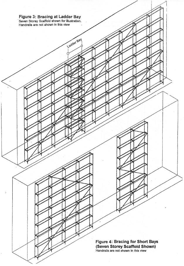
19 Static Walk-Thru Face Scaffolds Maximum Platform Levels The maximum number of platform levels is seven when the scaffolding is for light duty and three when for medium duty, as defined in AS/NZS 1576 (2.2kN and 4.4kN per bay respectively). Platforms Platforms comprise an integral part of the scaffold structure and shall be installed on all levels. The exception is at the ground level where a continuous horizontal brace may be installed in place of a platform. Diagonal Bracing Diagonal bracing on one side (generally the side away from the building) is required and is required to be installed as shown on Figures 1, 2 and 4, except where interrupted by ladder bays (see separate note). They are to be installed from top to bottom in one line. A new line is to commence after every seven bays. Thus, for the long seven level scaffold (which is the maximum height permitted) shown in Figure 1, a new line is commenced just as the first line reaches the top of the scaffold. For the long four-level scaffold shown in Figure 2, the same principle applies. In the sketch of this scaffold, the new line commences three bays after the first line reached the top of the scaffold, but still starts seven bays after the first line starts. Diagonal Bracing for Short Scaffolds Where the bracing reaches the end of the scaffold before it reaches the top, which will be the case where the number of bays is less than the number of storeys, as shown in Figure 4 for seven story scaffold, the braces need to continue in the opposite direction dog-legging until the top is reached. Diagonal Bracing at Ladder Bays Where the main bracing is interrupted at the ladder bay, the brace shall be restarted on the far side of the bay at the same platform level. The outer side of the ladder bay itself is to be braced with dog-leg bracing full height. This is illustrated in Figure 3. Bracing to the Building The scaffolding is to be connected to the building with devices capable of transmitting loads of 6.0kN in either tension or compression. These connections are to be spaced horizontally at every frame and vertically at every second platform level. Please Ensure that: Work is performed safely. Walk thru upper frames are not substituted for base frames. If scaffold is being erected on uneven ground scaffold is levelled using height adjustable screwjacks. Site is left clear of all surplus components, equipment, tools and debris. Page 18
20 Page 19
21 Page 20
22 Scaffolding Checklist Scaffold Vicinity Has sufficient public protection been provided? Have sufficient safeguards against electric power lines been provided? Is there sufficient control over vehicle movement? Is there sufficient control over crane operation? Supporting Structure Is the supporting structure in good condition? Does the supporting structure have adequate strength? Are there sufficient controls to prevent adverse deterioration of the supporting structure? Are all measures to strengthen the supporting structure adequate? Is the risk of the supporting structure being overloaded from other sources adequately controlled? Soleboards and Base Plates Checklist Are there sufficient soleboards? Are the soleboards of suitable material and in a serviceable condition? Minimum size for a timber soleboard is 200mm wide x 500mm long x 38mm deep. Are the soleboards secured? Are there sufficient base plates? Are the base Plates serviceable and of suitable dimension? Are the base plates secure? Scaffold Structure Checklist Are the standards bearing firmly? Are the standards plumb (or as designed)? Are the transoms level (or as designed)? Is the bracing adequate? Is the scaffold sufficiently stable? Are the ties correctly positioned and correctly fixed? Platforms Checklist Does the scaffold have the required number of working platforms? Are the working platforms at the required locations? Are the platforms and supporting scaffold constructed for the appropriate duty live loads? Are the platform dimensions suitable for the intended work? Is there adequate edge protection? Are the platforms correctly constructed? Page 21
23 Access and Egress Is there access and egress to all working platforms? Are temporary stairways correctly installed? Are portable ladders correctly installed? Are access ways and access platforms correctly installed? Containment Sheeting Has the scaffold been designed for wind loading on any containment sheeting? Are the fixing ties secured? Are there any rips or tears? Are the overlap joints satisfactory? General Fitness s for Purpose Is there adequate provision for material handling? Are the clearances between the scaffolds and adjacent structures correct? Is there adequate protection from falling debris? Has the scaffold been adequately designed to support all attachments? Are all approaches and platforms effectively lit? The Intended Duty of the Scaffold Including its Maximum Platform Capacity MultiScaff scaffolding is designed for a maximum live loading of 225kg swl (2.2kN) per bay single width scaffold and 450kg swl (4.4kN) per bay double width scaffold. Total loading of any single Equitpec scaffold tower (or equivalent) must not exceed 2000kg (including scaffold weight) even spread over 4 castors or baseplates. Light Duty: For example as used by painters, sign writers, maintenance staff etc: 225kg (2.2kN) per bay single width. Medium Duty: For example as used by solid plasterer or builder who because of his equipment may need medium duty scaffolding: 450kg (4.4kN) per bay double width scaffold. Heavy Duty: Aluminium scaffolding should NOT be used for heavy-duty 675kg (6.6kN) per bay eg bricklayers. For towers that could be exposed to wind load of have a height to base ratio greater than 3:1 specialised advice is available by telephoning Equiptec on MAXIMUM NUMBER OF WORKING PLATFORMS WORKING LOAD LIMITS (WIL) Page 22
24 A maximum of three medium duty 450kg working levels per tower is allowable for a scaffold with a maximum height of 10.2m NB. A typical working level consists of one MultiScaff scaffold platform for single width and two MultiScaff scaffold platforms for double width. ALWAYS ENSURE THAT YOU UNDERSTAND AND CAN COMPLY WITH THE REGULATIONS THAT APPLY TO THE ERECTION AND USE OF SCAFFOLDING IN THE AREA THAT YOU INTEND USING THIS EQUIPMENT. Wind Description Beaufort Force Speed (kph) Visible Indications Action Required Medium breeze Raises dust and loose paper, small branches move on trees. Fresh breeze Small trees in leaf begin to sway. Strong breeze Large branches in motion, umbrella s use with difficulty, telegraph wires whistle. Gale Force Twigs break off tree, progress generally impeded. Safe to work on tower. Cease to work on tower. Ensure that the tower is tied to a rigid structure and any loose platforms are tied down. Dismantle tower if storms forecast. A General Guide to Safe Scaffolding Work Practices Scaffolding is to be used in accordance with current Australian and New Zealand standards, DOL or OH & S requirements and codes of practice. Scaffolding is to be erected in accordance with planned hazard prevention and control measures including personal protective equipment to acceptable safe work practice and Equiptec s requirements. For safe and efficient erection, alteration and dismantling of scaffolding scaffolders must: Know the basic relevant rules of mechanics. Be able to understand the suppliers information, general site plans and specifications for scaffolds. (An ability to make simple calculations of dead load and live load is often needed.) Have a thorough knowledge of the scaffolding equipment being used. Have a thorough knowledge of the construction methods and design requirements associated with the equipment. Be able to recognise common hazards at the worksite and be capable of taking effective precautions to control risks to health and safety arising for these hazards. Visually inspect scaffolding for faults, safety and compliance with design and statutory requirements, codes of practice and guidelines. Page 23
25 Have the physical skills needed for scaffolding construction. Be competent in manual lifting techniques. Work safely and confidently at heights. Correctly use the various tools. Erect and dismantle scaffolding in the correct sequence. Carefulness, commonsense and caution are factors that cannot be built into scaffolding. These must be provided by the person(s) erecting, using, dismantling and maintaining the equipment. Maintenance Schedule After each job 1. Check graspers are tight in the tube. Replace rivets if loose. 2. Check grasper pin action is free. Replace any bent items. 3. Place platforms upside down and check that hooks receive tube well (ie not too tight or loose). 4. Check ply for any cracks, delaminations, dents or large holes. 5. Check ladder hook bolts are tight. 6. Check ladder stand-off operates correctly. 7. All base frames are fitted with plastic plugs internally on the standards to exclude dirt, plaster etc from interfering with the free turning of the jacks. Base frames should be turned upside down and tapped on the ground whenever a build up of foreign material occurs. If plugs should ever be damaged please call Equiptec, we will be glad to post replacements to you. 8. Check for any dents, deformations or cracks in aluminium extrusions. 9. Check castors wheel freely and adjust for height. 3 Monthly 1. Screwjacks should be fully wound out, brushed clean and lightly oiled. (We suggest kerosene and engine oil mixed 50:50.) 2. Brace grasper pins and springs should also be given a few drops of light oil, particularly if stored in the weather. 3. Check castor brakes are effective 4. Check outrigger couplers bolt on correctly. Page 24
26 When to discard component 1. If grasper or platform hooks become closed or extended in any way for any reason it should be discarded. 2. If a coupler is cracked it should be discarded. 3. Whilst mild denting or bowing of tube components may be straightened, if the component is creased it should be discarded. 4. Platform ply that is cracked, delaminated, deformed or has large holes in it. Contact Equiptec for clarification if in doubt. General Any cracks in welds should be ground out and repaired by a certified welder or returned to be repaired by certified Equiptec welding staff. Couplers and accessories should be maintained so that they can be used as intended, for example, nuts should be free running and swivels should turn freely. Avoid excessive oil, grease or paint, which can cause a coupler or accessory to slip. Do not apply heat to couplers and accessories. A bent plate of an adjustable base plate should be straightened. If straightening is not possible, the base plate should be replaced. Contact Details Should there be any further queries or you wish to discuss anything please don t hesitate to contact us and one of the team will be happy to assist. 1. Phone or sales@equiptec.co.nz 3. Fax: Physical address: 2 Ford Road Onekawa Napier 4110 Manufactured by: 5. Postal address: PO Box 3351 HBMC Napier 4142 Page 25
Customer Support Manual. This booklet contains information on how to erect, dismantle and use Waco Kwikform Aluminum Scaffolding.
 Customer Support Manual This booklet contains information on how to erect, dismantle and use Waco Kwikform Aluminum Scaffolding. WACO CUSTOMER SUPPORT MANUAL Page 0 of 70 Index Page Number Safety Information..
LADDERSPAN AGR. BoSS Camlock Advance Guardrail Mobile Aluminium Tower 1450/850 Frames USER GUIDE
 LADDERSPAN AGR BoSS Camlock Advance Guardrail Mobile Aluminium Tower 1450/850 Frames USER GUIDE Contents Safety First Safety Checklist Quantity Schedules Assembly and Dismantling Procedure Toe Boards Stabilisers
Mobile Towers - 3T Method
 Safety First Safety First INTRODUCTION SAFE USE Mobile Towers - 3T Method Please read this guide carefully. Please note that diagrams are for illustrative purposes only. User guides are also available
CLIMA 3T. Mobile Aluminium Tower with Climbing Frame 1450/850 3T - Through the Trapdoor Method USER GUIDE
 CLIMA 3T Mobile Aluminium Tower with Climbing Frame 1450/850 3T - Through the Trapdoor Method USER GUIDE Safety First Mobile Towers - 3T Method INTRODUCTION Please read this Userguide carefully. Please
Industrial Aluminium Towers
 Industrial Aluminium Towers SINGLE WIDTH LADDERSPAN & VERTICAL LADDER ERECTION MANUAL HORIZONTAL BRACE 1.8m (2040) 2.7m (2041) REVISED EDITION TOE BOARD 1.8m (2065) 2.7m (2067) LADDERSPAN TRAP PLATFORM
CLIMA 3T. Mobile Aluminium Tower with Climbing Frame 1450/850 3T - Through the Trapdoor Method USER GUIDE
 CLIMA 3T Mobile Aluminium Tower with Climbing Frame 1450/850 3T - Through the Trapdoor Method USER GUIDE Safety First Mobile Towers - 3T Method Introduction Please read this user guide carefully. Please
LADDERSPAN 3T USER GUIDE. Mobile Aluminium Tower 1450/850 Ladderspan. 3T - Through the Trapdoor Method
 LADDERSPAN 3T Mobile Aluminium Tower 1450/850 Ladderspan 3T - Through the Trapdoor Method USER GUIDE Safety First Mobile Towers - 3T Method INTRODUCTION Please read this user guide carefully. Please note
CLIMA AGR. Mobile Aluminium Tower with Climbing Frames 1450/850 Camlock Advanced Guardrail USER GUIDE
 CLIMA AGR Mobile Aluminium Tower with Climbing Frames 1450/850 Camlock Advanced Guardrail USER GUIDE Contents Safety First Safety Checklist Quantity Schedules Assembly and Dismantling Procedure Toe Boards
COMPONENT SCHEDULE SINGLE WIDTH SPAN TOWERS WITH LADDER FRAMES TO BSEN RUNG STARTER FRAMES
 COMPONENT SCHEDULE SINGLE WIDTH SPAN TOWERS WITH LADDER S TO BSEN 1004-2004 STARTER S PLATFORM HEIGHT METRIC 2.4 2.9 3.4 3.9 4.4 4.9 5.4 5.9 6.4 6.9 7.4 7.9 DESCRIPTION IMPERIAL 7 10 9 6 11 2 12 10 14
Mobile Tower 3T Method (Through The Trapdoor) Please read this guide carefully. Please note that diagrams are for illustrative purposes only.
 Please read this guide carefully. Please note that diagrams are for illustrative purposes only.") Mobile Tower 3T Method (Through The Trapdoor) INTRODUCTION Please read this guide carefully. Please note that diagrams are for illustrative purposes only. LOYAL mobile aluminium towers are light-weight
Mobile Tower 3T Method (Through The Trapdoor) INTRODUCTION Please read this guide carefully. Please note that diagrams are for illustrative purposes only. LOYAL mobile aluminium towers are light-weight
Industrial Aluminium Towers
 Industrial Aluminium Towers SINGLE WIDTH LADDERSPAN & VERTICAL LADDER ERECTION MANUAL TO BS-EN 1004-2004 Using 2 rung frames (Recommended) Using guardrail frames HORIZONTAL BRACE 1.8m (2040) 2.7m (2041)
Safety First Mobile Towers - 3T Method INTRODUCTION
 BoSS Room-Mate 3T - Through the Trap Method Safety First Mobile Towers - 3T Method INTRODUCTION Please read this guide carefully. Please note that diagrams are for illustrative purposes only. User guides
MiniMax USER GUIDE. Mobile Aluminium Trade Quality Access Tower System. 3T - Through The Trapdoor Method
 MiniMax Mobile Aluminium Trade Quality Access Tower System 3T - Through The Trapdoor Method USER GUIDE Contents Safety First Component Diagram Component Quantity & Safety Data Schedule Build Method Pre-use
BoSS. Mobile Aluminium Tower 1450/850 Ladderspan. 3T - Through the Trapdoor Method
 BoSS Mobile Aluminium Tower 1450/850 Ladderspan 3T - Through the Trapdoor Method USER GUIDE Edition November 2011 Safety First Mobile Towers - 3T Method INTRODUCTION Please read this guide carefully. Please
This User Guide provides you with step by step instructions to ensure your system is erected easily and safely.
 INTRODUCTION Please read this guide carefully. Please note that diagrams are for illustrative purposes only. Trade King 730 mobile aluminium towers are light-weight scaffold towers used throughout the
ROOM-MATE. 3T - Through the Trapdoor USER GUIDE
 ROOM-MATE 3T - Through the Trapdoor USER GUIDE Safety First Introduction Please read this user guide carefully. Please note that diagrams are for illustrative purposes only. User guides are also available
BoSS Clima USER GUIDE. Mobile Aluminium Tower with Climbing Frame 1450/850. 3T - Through the Trapdoor Method
 BoSS Clima Mobile Aluminium Tower with Climbing Frame 1450/850 3T - Through the Trapdoor Method USER GUIDE Edition April 2009 Safety First Mobile Towers - 3T Method INTRODUCTION Please read this guide
LEWIS Miniscaff Folding Tower Assembly Guide
 LEWIS Miniscaff Folding Tower Assembly Guide This document is a complete guide for the LEWIS Miniscaff Towers The user should read the entire contents of this document before commencing assembly and pay
Safety First Mobile Towers - 3T Method INTRODUCTION
 Safety First Mobile Towers - 3T Method INTRODUCTION Safety First SAFE USE BoSS Mobile Aluminium Tower 1450/850 Ladderspan 3T - Through the Trapdoor Method Please read this guide carefully. Please note
Industrial Aluminium Towers
 HORIZONTAL 1.8m (2040) 2.7m (2041) TOE BOARD 1.8m (2066) 2.7m (2068) Industrial Aluminium Towers DOUBLE WIDTH SPAN & VERTICAL ASSEMBLY GUIDE TO BS-EN 1004-2004 Using the 3T (Through the Trap ) Assembly
BoSS Climalite Camera and lighting tower
 Contents Safety First Safety First Quantity Schedules Toeboard 2 9 13 33 INTRODUCTION Please read this guide carefully. Please note that diagrams are for illustrative purposes only. User guides are also
8 Rung Industrial Tower
 A SAFER WAY TO REACH NEW HEIGHTS 8 Rung Industrial Tower Instruction Manual Mobile Access Tower 3T - Through the trap method Introduction This Assembly Guide is intended to provide you with step-by-step
Safety First Mobile Towers - 3T Method
 USER GUIDE Edition Aug 2011 MiniMax Mobile Aluminium Trade Quality Access Tower System 3T - Through the Trapdoor Method Safety First Mobile Towers - 3T Method INTRODUCTION Please read this guide carefully.
1450/850. Instruction Manual. Mobile Access Tower
 A SAFER WAY TO REACH NEW HEIGHTS 1450/850 Instruction Manual Mobile Access Tower 3T - Through the trap method Introduction This Assembly Guide is intended to provide you with step-by-step instructions
Industrial Aluminium Towers
 Industrial Aluminium Towers SINGLE WIDTH LADDERSPAN & VERTICAL LADDER ASSEMBLY GUIDE TO BS-EN 1004-2004 Using 2 rung frames (Recommended) Using Guardrail frames HORIZONTAL BRACE 1.8m (2040) 2.7m (2041)
Safety First Mobile Towers - 3T Method
 Safety First Mobile Towers - 3T Method INTRODUCTION Please read this guide carefully. Please note that diagrams are for illustrative purposes only. User guides are also available to download from our website
BoSS Room-Mate. 3T - Through the Trap Method
 BoSS Room-Mate 3T - Through the Trap Method User Guide Edition 2: 2010 Safety First Mobile Towers - 3T Method INTRODUCTION Please read this guide carefully. Please note that diagrams are for illustrative
Inspect components prior to erection. Inspect tower prior to use. Castors locked and legs correctly adjusted. Stabilisers fitted as specified
 Introduction This Guide is designed to provide you with step bystep instructions to ensure that your system is erected with themaximum of ease and safety. Before assembly, please read thesafety notes.
Safety First Mobile Towers - 3T Method INTRODUCTION. Please read this guide carefully. Please note that diagrams are for illustrative purposes only.
 BoSS Mobile Aluminium Tower 0/80 Ladderspan T - Through the Trapdoor Method Safety First Mobile Towers - T Method INTRODUCTION Please read this guide carefully. Please note that diagrams are for illustrative
Assembly Instructions
 Assembly Instructions BAILEY Ladders Mini Rise Mobile Scaffold Pack Schedule Working Height (m) 2.9 3.7 5.7 Platform Height (m) 0.9 1.7 3.7 Description Wt Pack Qty. Base Pack 34kg 1 1 1 Guardrail Pack
Span 300 Manual. DESIGNATION EN1004 CEN 1298 IM - en. CEN designation of this instruction manual EN 1298 IM en
 Span 300 Manual DESIGNATION EN1004 CEN 1298 IM - en CEN designation of this instruction manual EN 1298 IM en WARNING NEVER STAND ON AN UNGUARDED PLATFORM SAFE WORKING LOADS AND WORKING HEIGHTS The safe
SAFE ERECTION AND USE OF ALUMINIUM TOWERS/SCAFFOLDS
 SAFE ERECTION AND USE OF ALUMINIUM TOWERS/SCAFFOLDS PERSONNEL DIVISION Revised 2002 CONTENTS Page 1 INTRODUCTION 1 2 APPLICATION 1 3 ERECTION AND INSPECTION 1 4 ERECTION 1 4.1 Before erection of tower
Assembly Instructions
 MULTI-FUNCTIONAL SCAFFOLD UNIT + STABILIZER LEGS 1. SCAFFOLD 2. LADDER 3.TRESTLE 2 1 3 Assembly Instructions CODE: 126431 Parts List Specifications: - Width: 1.2m - Length: 1.6m - Scaffold Height: 3.4m
Single Width Tower Assembly Guide
 Unit 1 Bellingham Trading Estate Franthorne Way London SE6 3BX T: 0845 257 599 E: info@scaffold-tower.co.uk W: www.scaffold-tower.co.uk This document will provide all users of Lewis Access Towers with
MOBILE ACCESS TOWER INSTRUCTION MANUAL SHALLOW BRACE. Incorporating the 3T method of assembly
 MOBILE ACCESS TOWER Incorporating the 3T method of assembly SHALLOW BRACE INSTRUCTION MANUAL 2 INTRODUCTION This instruction manual contains all the information required to correctly assemble the OCTO
INSTRUCTION MANUAL MOBILE ACCESS TOWER
 INSTRUCTION MANUAL MOBILE ACCESS TOWER CONTENTS Safety First.......... 3-6 Component Diagrams......... 7-9 Component Quantity & Safety Data Schedule.... 10 Build Method.......... 11-24 Pre-use Safety Inspection
Span 300 Instruction Manual
 Span 300 Instruction Manual DESIGNATION SPAN300 Double Width EN 1004 3 8/12 XXCD SPAN 300 Single Width EN 1004 3 8/8 XXCD CEN designation of this instruction manual EN 1298 IM en Rev-00 WARNING NEVER STAND
Span 400 Instruction Manual
 Span 400 Instruction Manual DESIGNATION SPAN 400 Double Width EN 004 3 8/2 XXCD SPAN 400 Single Width EN 004 3 8/8 XXCD CEN designation of this instruction manual EN 298 IM en Rev-00 WARNING NEVER STAND
A SAFER WAY TO REACH NEW HEIGHTS. Instruction Manual. Mobile Access Tower. 3T - Through the trap method
 A SAFER WAY TO REACH NEW HEIGHTS UTS1450/850 Instruction Manual Mobile Access Tower 3T - Through the trap method Introduction This Assembly Guide is intended to provide you with step-by-step instructions
GENERAL SAFETY RULES DOUBLE WIDTH 232 (NARROW RUNG) 3T INSTRUCTION MANUAL DISMANTLING NOTES: The 232 Tower Approved to the requirements of BS EN 1004
 3T INSTRUCTION MANUAL DISMANTLING NOTES: The 232 Tower Approved to the requirements of BS EN 1004") GENERAL SAFETY RULES DOUBLE WIDTH 232 (NARROW RUNG) 3T INSTRUCTION MANUAL The 232 Tower Approved to the requirements of BS EN 1004 MAX SAFE WORKING LOAD FOR STRUCTURE: 750KG MAX SAFE WORKING LOAD FOR PLATFORM:
GENERAL SAFETY RULES DOUBLE WIDTH 232 (NARROW RUNG) 3T INSTRUCTION MANUAL The 232 Tower Approved to the requirements of BS EN 1004 MAX SAFE WORKING LOAD FOR STRUCTURE: 750KG MAX SAFE WORKING LOAD FOR PLATFORM:
STAIRMAX 700. Camlock Guardrail Aluminium Tower 3T - Through the Trapdoor USER GUIDE
 STAIRMAX 700 Camlock Guardrail Aluminium Tower 3T - Through the Trapdoor USER GUIDE Contents Safety First Component Diagram Quantity Schedule Build Method Pre-use Safety Inspection Checklist 2 10 11 12
ONE MAN TOWER. Instruction/safety manual
 ONE MAN TOWER Instruction/safety manual The UTS One Man Tower is both quick and easy to assemble and can be erected and dismantled by a single person. Safety Information IMPORTANT: Never use the ONE MAN
Reliant Holdings Ltd Safety Management System
 Preparation: Safety Mgr Authority: President Issuing Dept: Safety Page: Page 1 of 7 Purpose The purpose of this program is to prevent injuries due to falls from elevated work areas and ensure employees
SOLO 700. One Man Aluminium Tower 3T - Through the Trapdoor Method USER GUIDE
 SOLO 700 One Man Aluminium Tower 3T - Through the Trapdoor Method USER GUIDE Contents Safety First Component Diagram Quantity Schedules Stabilisers Build Method 2 7 9 10 11 1 BoSS SOLO 700 User Guide Safety
Span 400 Series Instruction Manual
 Span 400 Series Instruction Manual DESIGNATION 400 400 004 3 8 2 400 400 004 3 8 8 CEN designation of this instruction manual EN 298 IM en Rev-0 WARNING NEVER STAND ON AN UNGUARDED PLATFORM SAFE WORKING
Span 500. Elite Instruction Manual. DESIGNATION SPAN 500 Double Width EN /12 XXXD SPAN 500 Single Width EN /8 XXXD
 Span 500 Elite Instruction Manual DESIGNATION SPAN 500 Double Width EN 1004 3 8/12 XXXD SPAN 500 Single Width EN 1004 3 8/8 XXXD CEN designation of this instruction manual EN 1298 IM en Rev-02 WARNING
ASSEMBLY INSTRUCTION ROLLING TOWER RT 1400 & RT 1400XR ROLLING TOWER RT 750 & RT 750XR STAIR TOWER ST 1400 FOLDABLE TOWER FT 750 & FT 750XR
 ASSEMBLY INSTRUCTION ROLLING TOWER RT 1400 & RT 1400XR ROLLING TOWER RT 750 & RT 750XR STAIR TOWER ST 1400 FOLDABLE TOWER FT 750 & FT 750XR EN 1298 - IM - en SC1809 12 SAFETY IN EVERY STEP wibeladders.com
Construction Safety Education Forum. 6 March Scaffolding. Dimitri Barlas, State Coordinator Construction Work Health and Safety Division DRAFT
 Construction Safety Education Forum 6 March 2013 Scaffolding Dimitri Barlas, State Coordinator Construction Work Health and Safety Division DRAFT SRWSD in confidence 1 Presentation Outline Introduction
SIDE CANTILEVER TOWER SCAFFOLD. 3T - Through the Trapdoor Method USER GUIDE
 SIDE CANTILEVER TOWER SCAFFOLD 3T - Through the Trapdoor Method USER GUIDE Contents Safety First Component Diagram Component Quantity & Safety Data Schedule Build Method Pre-use Safety Inspection Checklist
BoSS SOLO 700. One Man Aluminium Tower EN /4 EN1298-IM-EN 3T - Through the Trap Door USER GUIDE
 BoSS SOLO 700 One Man Aluminium Tower EN1004-3-4/4 EN1298-IM-EN 3T - Through the Trap Door USER GUIDE Edition August 2013 Contents Safety First 2 Component Diagram 7 Quantity Schedules 9 Stabalisers 10
Instruction Manual. DESIGNATION SPAN 500 Double Width EN /12 XXXD SPAN 500 Single Width EN /8 XXXD
 Instruction Manual DESIGNATION SPAN 500 Double Width EN 1004 3 8/12 XXXD SPAN 500 Single Width EN 1004 3 8/8 XXXD CEN designation of this instruction manual EN 1298 IM en Rev-02 WARNING NEVER STAND ON
STAIRMAX 700 MK2 USER GUIDE. Aluminium Tower 700 Climbing Rung. 3T - Through The Trapdoor Method
 STAIRMAX 700 MK2 Aluminium Tower 700 Climbing Rung 3T - Through The Trapdoor Method USER GUIDE Contents Safety First Component Diagram Component Quantity & Safety Data Schedule Build Method Pre-use Safety
3T - Through The Trapdoor Method
 ALTO MEDIUM DUTY STAIRWELL TOWER Aluminium Access Tower ISSUE 3 Instruction Manual EN 1298-IM-EN The ALTO MD Stairwell Tower 3T - Through The Trapdoor Method Lakeside Industries Ltd www.altoaccess.com
AGR TOWER. Standard Features include. Tower Assembly Training Available
 AGR TOWER The Euro Tamper Proof Advanced Guardrail is another solution to safe tower assembly. The ergonomic design lends itself to quick easy assembly and provides collective fall prevention before the
3T - Through The Trapdoor Method
 ALTO HEAVY DUTY SINGLE WIDTH LADDERSPAN TOWER Mobile Aluminium Access Tower ISSUE 5 Instruction Manual EN 1298-IM-EN The ALTO HD Ladderspan Tower is certified to BS EN 1004:2004 3T - Through The Trapdoor
Mobile Tower Scaffold. 1. INTRODUCTION 2. REGULATIONS 3. PRIOR TO ERECTION 4. MOVING A TOWER 5. INSPECTION 6. HAZARDS
 Mobile Tower Scaffold. 1. INTRODUCTION 2. REGULATIONS 3. PRIOR TO ERECTION 3.1 Before Erection of Tower 3.2 Stability of Tower 3.3 Access & Guardrails 3.4 Height 3.5 Outriggers & Stabilizers 3.6 Tying-in
INSTRUCTIONmanual. BoSS COMPACT SIDE CANTILEVER TOWER SCAFFOLD 3T Method - Through the Trap Door
 INSTRUCTIONmanual BoSS COMPACT SIDE CANTILEVER TOWER SCAFFOLD 3T Method - Through the Trap Door Drawn: 26/02/2018 Issue: E Page: 2 OF 21 CONTENTS Safety First Component Diagram Component Quantities & Safety
AR SCAFFOLDING AR ALUMINUM MOBILE AR STEEL MOBILE
 SAFETY RULES and INSTRUCTIONS FOR AR SCAFFOLDING AR ALUMINUM MOBILE AR STEEL MOBILE INTERIOR or EXTERIOR USE ! WARNING! Improper assembly, dismantling or use of Multi-Use Scaffold may result in serious
 Instruction Manual Span Scaffolds! W A R N I N G! Before using Instant UpRight Scaffolds, read, understand and follow all Safety Rules, Erection Instructions and Maintenance Rules. Keep this manual for
Instruction Manual Span Scaffolds
 Instruction Manual Span Scaffolds QUALITY & STRENGTH YOU CAN TRUST! W A R N I N G! Before using Instant UpRight Scaffolds, read, understand and follow all Safety Rules, Erection Instructions and Maintenance
STANDARD PRACTICE INSTRUCTION
 STANDARD PRACTICE INSTRUCTION DATE: March 1, 2001 SUBJECT: Scaffolding Safety Program. REGULATORY STANDARDS: 29 CFR 1910.28 Safety Requirements For Scaffolding. 29 CFR 1910.29 Manually Propelled Mobile
Snappy Ladder 300 Instruction Manual
 Snappy Ladder 300 Instruction Manual DESIGNATION: SNAPPY LADDER 300 EN 1004 3 4/4 XXCD CEN designation of this instruction manual EN 1298 IM en Rev-01 This assembly instruction is designed to provide a
Rolling Towers. Layher Uni Light Tower Instructions for Assembly and Use. Mobile working platforms according to DIN EN 1004:
 Instructions for ssembly and Use Mobile working platforms according to DIN EN 00:00-03 Working platform 0.7 x.8 m max. working height: indoors.3 m outdoors.3 m Rolling Towers Load bearing capacity.0 kn/m
SCAFFOLDING PROCEDURE
 SCAFFOLDING PROCEDURE 1 Table of Contents 1 PURPOSE... 3 2 PROGRAM COMPLIANCE... 3 3 SCOPE... 3 4 DEFINITIONS... 3 5 RESPONSIBILITES... 4 6 SCAFFOLD INSPECTION... 5 7 SCAFFOLD USE... 5 8 SCAFFOLD REQUIREMENTS...
ASSEMBLY.
 ASSEMBLY www.proscaf.com ASSEMBLY SECTION Points to Consider These assembly instructions are generic and may not apply to all applications. If you have questions regarding specific applications contact
Scaffolds. OSHA Office of Training & Education 1
 Scaffolds OSHA Office of Training & Education 1 What Is A Scaffold? An elevated, temporary work platform Three basic types: Supported scaffolds -- platforms supported by rigid, load bearing members, such
EASY-SET SCAFFOLD TOWER OPERATIONAL SAFETY AND ASSEMBLY INSTRUCTIONS MODEL: AL-Q0107. Customer Service
 MODEL: AL-Q0107 EASY-SET SCAFFOLD TOWER OPERATIONAL SAFETY AND ASSEMBLY INSTRUCTIONS Picture may differ from actual product. READ THESE INSTRUCTIONS CAREFULLY BEFORE USING THIS PRODUCT. KEEP THIS MANUAL
EASY-SET SCAFFOLD TOWER OPERATIONAL SAFETY AND ASSEMBLY INSTRUCTIONS MODEL: AL-Q0106. Customer Service
 MODEL: AL-Q0106 EASY-SET SCAFFOLD TOWER OPERATIONAL SAFETY AND ASSEMBLY INSTRUCTIONS Picture may differ from actual product. READ THESE INSTRUCTIONS CAREFULLY BEFORE USING THIS PRODUCT. KEEP THIS MANUAL
As a scaffold user, Mr Scaffold recommends Method 1, but both options are suitable.
 20 EASYSCAF t TM The Next Level 1300 MR SCAFFOLD (1300 677 223) 12 Lagana Place Wetherill Park NSW 2164 Fax: (02)9725 5214 ABN: 65 088 652 144 Re: Workcover Update Feb 2011 Thankyou for purchasing your
Scaffolds. OSHA Office of Training & Education 1
 Scaffolds OSHA Office of Training & Education 1 What Is A Scaffold? An elevated, temporary work platform Three basic types: Supported scaffolds -- platforms supported by rigid, load bearing members, such
Scaffolding. Safety Guide. STOP! Before you climb
 Scaffolding Safety Guide Printed FEB 2015 rebr. AUG 2016 Contents Safety Guide Disclaimer... 1 Safety Guide Objectives... 2 Roles & Responsibilities of Workplace Parties Employers, Supervisors, Workers...
Rolling Towers. Layher Rolling Towers Uni Wide. Safety Structure Instructions for Assembly and Use. Mobile working platforms to DIN EN 1004:
 Layher Rolling Towers Uni Wide Safety Structure Instructions for Assembly and Use Mobile working platforms to DIN EN 1004:2005-03 Working platform 1.5 x 2.85 m Rolling Towers max. working height: indoors
Elevated Work Safety Meeting
 Elevated Work Safety Meeting 1 Elevated Work There are many jobs that require working at heights This requires the use of walking working surfaces such as ladders, scaffolds and stairways Safety in elevated
EASY-SET SCAFFOLD TOWER OPERATIONAL SAFETY AND ASSEMBLY INSTRUCTIONS MODEL: AL-Q0108. Customer Service
 MODEL: AL-Q0108 EASY-SET SCAFFOLD TOWER OPERATIONAL SAFETY AND ASSEMBLY INSTRUCTIONS Picture may differ from actual product. READ THESE INSTRUCTIONS CAREFULLY BEFORE USING THIS PRODUCT. KEEP THIS MANUAL
USER S MANUAL HAKI PUBLIC ACCESS STAIR
 USER S MANUAL HAKI PUBLIC ACCESS STAIR HAKI AB 2017 Important information HAKI s product liability and user s manuals apply only to scaffolds that are entirely composed of components that have been made
Universal Panels & Accessories
 Universal Panels & Accessories Erection Procedures INTRODUCTION Use common sense when working with Scaffold Your Safety is our #1 Concern Universal Scaffolds are designed with your safety in mind every
SAFETY SYSTEM. G-Deck Consideration. Manual Handling
 INTRODUCTION The G-Deck load deck system is a high strength, low cost access platform which is quick to erect, durable and flexible enough to meet your site access needs. Safety is a priority and G-Deck
Aluminum Scaffold Safety Rules
 Aluminum Scaffold Safety Rules Special Precautions 1. Do not permit anyone to use Up-Right Scaffolds unless he is familiar with these rules. 2. If in doubt as to the ability of an Up-Right Scaffold to
Layher. Aluminium Rolling Towers. Layher SuperKlaxTower. Instructions for Assembly and Use
 Mobile access and working towers in accordance with: HD 1004; DIN 4422, Part 1 (Version 8/92) Working platform 2.8 x 2.8 m and 2.8 x 1.95 m Max. working height: in closed rooms 13.95 m, outdoors 10.0 m
Safety Documents > Safety Manual > Scaffolds
 Safety Documents > Safety Manual > Scaffolds D. Scaffolds 1. General Requirements for All Scaffolds a. Scaffolds shall be furnished and erected in accordance with this standard for persons engaged in work
PORTABLE LADDER SAFETY
 LADDER AND SCAFFOLD SAFETY PLAN Ladder & Scaffold Safety Falls can result in serious injury or death. Falls from a higher elevation account for approximately 10% of workplace fatalities and 5.2% of nonfatal
USER S MANUAL HAKI PUBLIC ACCESS STAIR
 USER S MANUAL HAKI PUBLIC ACCESS STAIR HAKI AB 2018 Important information HAKI s product liability and user s manuals apply only to scaffolds that are entirely composed of components that have been made
Sectional Scaffold. Scaffold Access Unit Installation Instructions
 Sectional Scaffold Scaffold Access Unit Installation Instructions 2 Scaffold Access Unit Installation Instructions SAU6 Painted: 18.3 lb Galvanized: 20.2 lb Label 7112A0003 NOTICE Please read and follow
Systems Scaffold Tubular Scaffold Access Unit Installation Instructions
 Systems Scaffold Tubular Scaffold Access Unit Installation Instructions 2 Tubular Scaffold Access Unit Installation Instructions LTUB7 Galvanized: 24.1 lb Label 7112A0003 NOTICE Please read and follow
BP U.S. Pipelines and Logistics (USPL) Safety Manual Page 1 of 7
 Safety Manual Page 1 of 7") Safety Manual Page 1 of 7 Scaffolds 1. Purpose This policy establishes the basic safety requirements and safe work practices for the erection, use, inspection, movement, and dismantling of scaffolding.
Safety Manual Page 1 of 7 Scaffolds 1. Purpose This policy establishes the basic safety requirements and safe work practices for the erection, use, inspection, movement, and dismantling of scaffolding.
SAFE WORK PROCEDURE LOCATION OF WORK: WRITTEN BY: APPROVED BY: DATE: LAST REVISION: Leon Prevost Brent Vandenbosch
 Page 1 of 6 LOCATION OF WORK: WRITTEN BY: APPROVED BY: DATE: LAST REVISION: All Schools L. Carriere Lorne Turner Leon Prevost Brent Vandenbosch June 12, 2013 July 7, 2017 HAZARDS PRESENT Pinch points Falling
OSHA Rules for Scaffolding
 OSHA Rules for Scaffolding A) Objectives: 1. 2. 3. Don t let the scaffold fall. Don t fall off the scaffold. Don t let the material fall off the scaffold. Name of Competent Person: Name of Qualified Person:
Sample Written Program. For. Scaffolds
 Sample Written Program For Scaffolds 1 Scaffold Safety Program (COMPANY NAME) Purpose The purpose of this safety policy and procedure is to establish guidelines for the protection of {COMPANY} employees
 QUICK ALLY SCAFFOLD SPECIFICATIONS Standards: 1.0 m, 1.5 m, 2.0 m, 2.5 m, 3.0 m, 4.0 m. Ledgers: 0.5 m, 0.7 m, 1.2 m, 1.8 m, 2.4 m, 3.0 m. Polypropylene platforms: 0.7 m, 1.2 m, 1.8 m, 2.4 m, 3.0 m. Also
Safety on Heights: Our Policy
 11/17/14 Safety on Heights: Our Policy Only volunteers over the age of 18 are allowed to work on heights of more than six feet off the ground. This includes all work on scaffolds. Only volunteers who are
ANID GROUP SARL. For. Scaffolds
 ANID GROUP SARL For Scaffolds 1 Scaffold Safety Program Anid Group SARL Purpose The purpose of this safety policy and procedure is to establish guidelines for the protection of Anid Group employees who
TEMPORARY EDGE PROTECTION SYSTEM DESCRIPTION CTS. Combisafe International AB
 TEMPORARY EDGE PROTECTION SYSTEM DESCRIPTION CTS Combisafe International AB CTS Combisafe International AB Contents Safety instructions... 3 Important... 4 General... 4 Data... 5 Safety posts 4140/4145/4150...
INTER-DEPARTMENTAL PROCEDURE
 INTER-DEPARTMENTAL PROCEDURE OPERATIONS - DUKHAN FIELDS Operations Manager, Dukhan Fields Director Operations Rev. Date Reason A4 Mar13 Issued for use OSD / QC: Rev No. Rev Date DOCUMENT CHANGE HISTORY
Scaffolding and Raised Platforms
 Standard Operating Procedures Scaffolding and Raised Platforms Last Modified: JAN 2013 1 of 7 Scaffolding and Raised Platforms I Purpose To provide a guideline for personnel who work around or on stationary
Tower ASSEMBLY GUIDE
 Tower ASSEMBLY GUIDE Contents Introduction Section Contents Introduction Know Your MiTOWER Know Your MiTOWER s Components Know Your Kit List and Specifications Know Your Storage and Transport Pack Safety
TAKING YOU TO NEW HEIGHTS IN SAFETY... kwikstage
 limited one bay kwikstage stair unit user guide One Bay Stair Tower used in conjunction with Kwikstage System Scaffolding and designed to conform to all current British and European Standards. With only
Supported Scaffold Inspections
 Supported Scaffold Inspections May 2016 Inspect scaffolds and scaffold parts daily, before each work shift, and after any event that may have caused damage. Check to see if power lines near scaffolds are
Illinois State University. Scaffolding Procedure
 Illinois State University Scaffolding Procedure Illinois State University Facilities Management Revision Date: May 2016 Illinois State University Facilities Management Scaffolding Procedure 1.0 Purpose
WORKING AT HEIGHT. The company will comply with the Work at Height Regulations 2005, its schedules and Codes of Practice.
 WORKING AT HEIGHT The company will comply with the Work at Height Regulations 2005, its schedules and Codes of Practice. Principally this means that we comply with the hierarchy of risk in that we shall:
Scaffolding Safety. Scaffolding
 Scaffolding Safety Scaffolding 1926.450 - Scope, Application Covers all scaffolds used in workplaces Does not apply to crane or derrick suspended personnel platforms, which are covered by 1926.550(g) Aerial