Tutorial of CUFSM4. Objectives. Example. - C-section with lips
|
|
|
- Constance Young
- 6 years ago
- Views:
Transcription
1 Tutorial of CUFSM4 Objectives - Introduce the basic methods of modeling thinwalled structures and calculating elastic critical buckling load (P cr ) or elastic critical distortional buckling moment (M cr ) - Some discussion about the effect of boundary condition and modal decomposition and identification (cfsm) Example - C-section with lips 1
2 Tutorial General procedure - Input the coordinates of each node on the cross-section - Divide structural elements - Set material properties - Specify the boundary conditions, number of eigenvalues, and a series of half-wave lengths - Choose the basis vector and base vectors of various modes in cfsm (Optional) - Define loads on the cross-section - Calculation and the post-process of results 2
3 Welcome interface - On the left side: load an existent file or save your work - In the middle: input data, set boundary conditions, add constraints on modes (cfsm) and halfwavelengths, submit your work for calculation, show curves of the results - On the right side: zoom in, zoom out, reset the amplification, print, copy the screen, reset, info & close the program 3
4 4
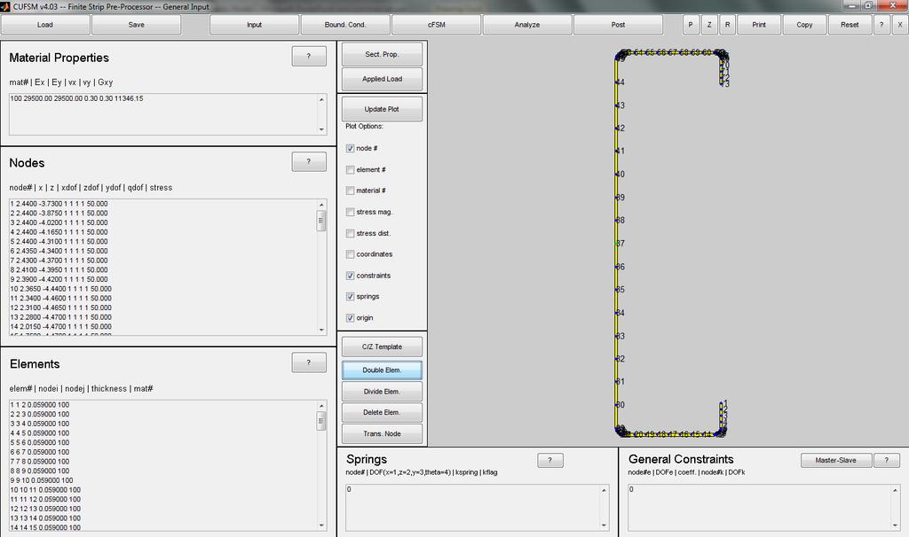
5 Main interface - Choose which properties you would like to be shown on the screen by tick them out and click Update Plot (here we choose no#, constrains, springs and origin) 5
6 6
7 Input coordinates of nodes - For a concrete section, specify the coordinates of each node, and input them respectively. - A dof is given the value of zero for constraint; while one for free movement (normally one). - If you are not sure with the stress, just assume them as uniform one. (We will do with them later) - For some cross-section (like C and Z), template can be used. 7
8 8
9 Divide structural elements - Mat# is the material that will be defined (there are default values). - The division of elements near the round corner should be more refined. - Some buttons (like Double Elem. and Divide Elem.) helps, like to double your mesh or refine your mesh further. A doubled mesh is shown in the next slide. 9
10 10
11 Set material properties and element connections - Material properties include Mat#, Young s modulus, Poisson s ratio and Shear modulus (Usu. Young s modulus is ksi for CFS, and Poisson s ratio is 0.3). - The software also allows different Young s moduli for two principal axes. - Elements should numbered and start and end nodes, thickness and material number of each element should be given. 11
12 Set boundary conditions and a series of half-wave lengths (traditional signature curve) - After clicking boundary condition, traditional signature curve means only one term of triangular series will be used for a specified half-wave length (m is locked to 1 for (mπy/l)). This is the only possible value of m in past editions. - The user are free to choose the boundary conditions, and the curve of longitudinal shape functions are shown at the lower-right corner. (Only pin-pin are available in the past.) 12
13 Set boundary conditions and a series of half-wave lengths (traditional signature curve) - The number of eigenvalues is exactly the number of buckling load factors you would like the software to solve for each half-wave length. For those who interested in higher modes, you can choose a larger number. - The number of half-wave lengths should be enough, or you may miss some critical loads (can be modified after a trial). Remember local, distortional and global bucklings differ in half-wave lengths. 13
14 14
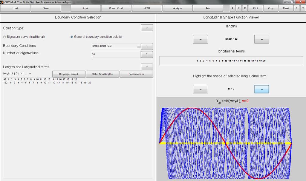
15 Set boundary conditions and a series of half-wave lengths (general boundary condition solution) - General boundary condition solution means a certain number of terms of triangular series will be used for a specified half-wave length (m can be larger than one for (mπy/l)). Note that we choose m from 1 to 20 for 92 inch half-wave length, and the shape functions are shown in slide 17 with m = 2 highlighted by red line. - The user are also free to choose the boundary conditions, number of eigen-values and half-wavelengths (like explained in slide 12 and 13). 15
16 Set boundary conditions and a series of half-wave lengths (general boundary condition solution) - One key is that if you use m = 2 for half-wave length 2L, with other conditions the same, you will get the same results with m = 1, half-wave length L, since m and halfwave length are both doubled. Wisely choose them. - The recommend m means a traditional signature curve analysis will be run automatically, and the software will suggest you the m which resolves the half-wave lengths close to the critical half-wave lengths of local, distortional and global modes. 16
17 17
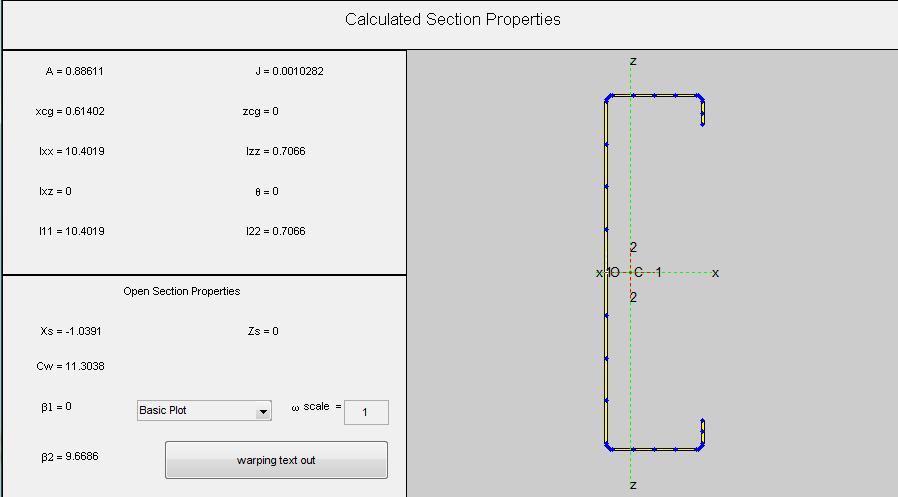
18 Define loads on the cross-section - Press Sect. Prop. the software will automatically calculate the properties of the cross-section. - In, Applied Load, input the yield stress, the software will automatically calculate the axial force and moment on the cross-section. - Note that only the checked axial force or moment will be used in calculation. Make sure before press Generating Stress. Then there will be a stress distribution at every node. 18
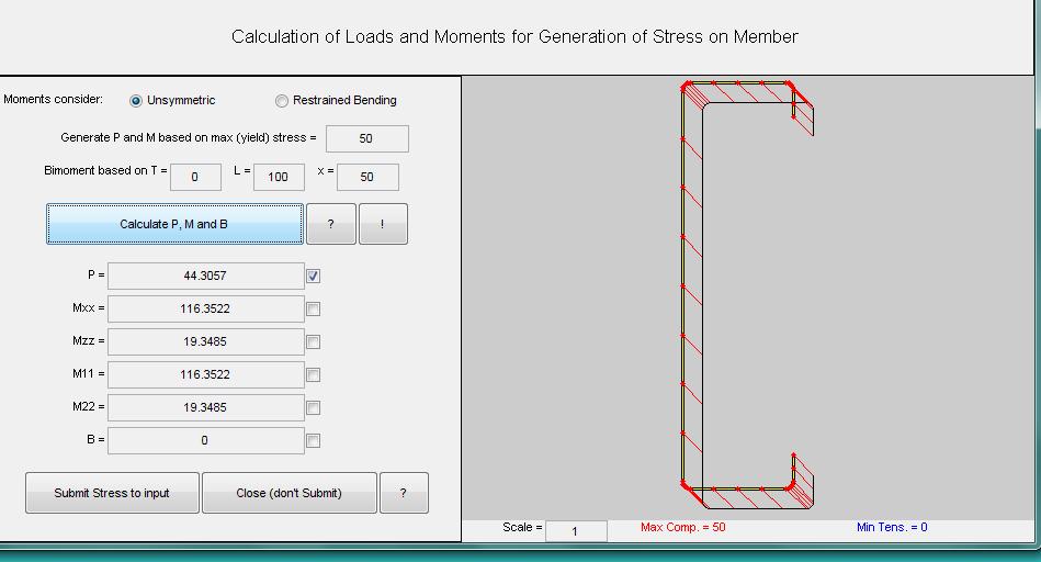
19 19
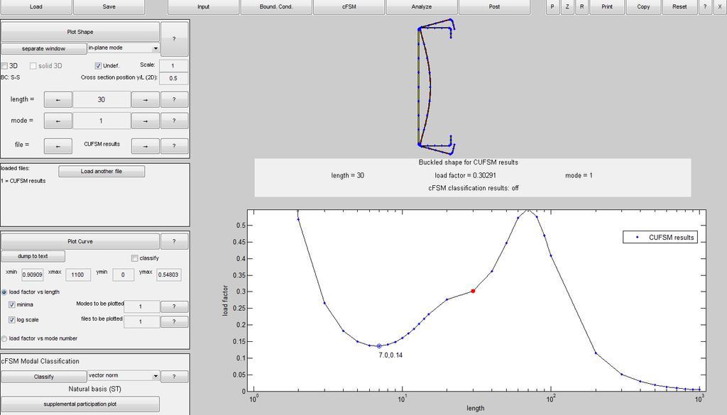
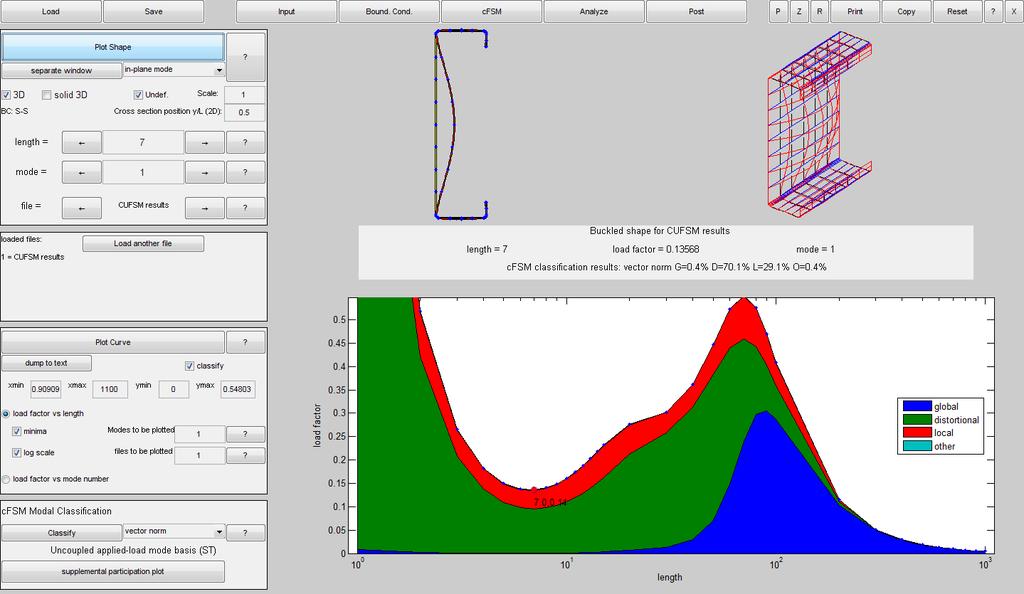
20 Calculation and the post-process of results - Click Analyze will start the calculation. - Then, click Post to show the results. - The curve of buckling load-factor vs. halfwavelength contains all the information. 20
21 About the curve of buckling load-factor vs. halfwavelength - Critical buckling load of a certain buckling mode (local, or distortional) is the local minimum on the curve. While the global buckling half-wave length should be the physical length of the member. - There are cases where we have only one local minimum (like on slide 23) or multiple local minima. - Generally, we tell the modes apart by their halfwavelengths and mode shapes. A more physical way is to use cfsm (we will explain later). 21
22 About the curve of buckling load-factor vs. halfwavelength - The Plot Shape button will let you see the mode shape of buckling (2D or 3D) at a specific point on the curve. Use the scroll bar to see every mode (less than your number of eigenvalues) of every half-wavelength. - You may also load another curve for comparison by clicking load another file. - This edition allow you to dump your results into documents and can do modal classification and decomposition. 22
23 23
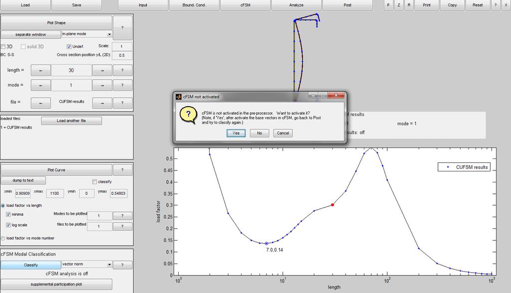
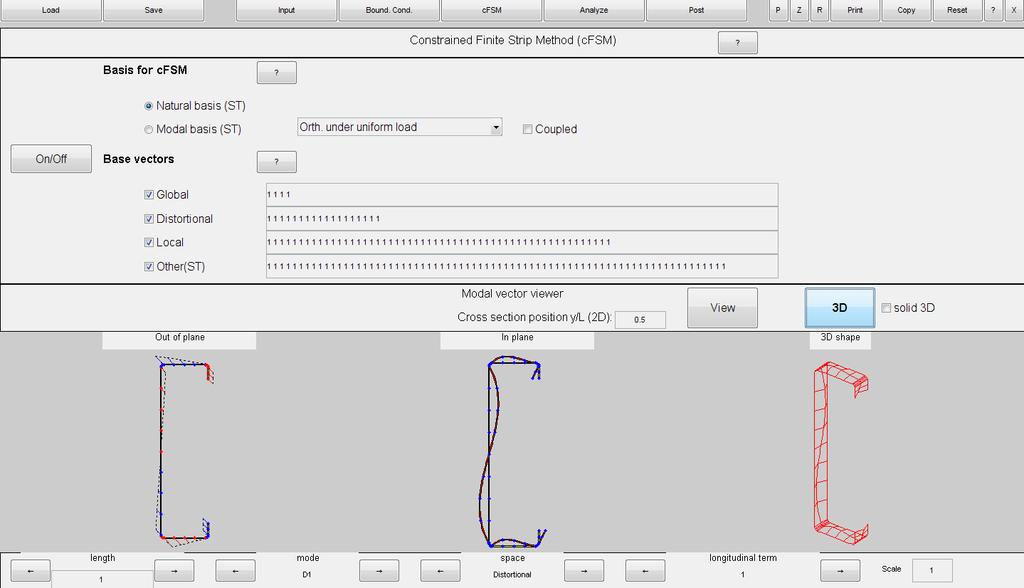
24 cfsm - constrained fininte strip method, modal decomposition and identification (details are in the paper posted on Dr. Schafer s website) - If you click classify under cfsm Model classification at the lower-left corner, their will be a pop-out informing you to initiate cfsm. - After choosing yes, you will be directed to cfsm page. The first thing is to choose the base vector (natural or orthogonal) 24
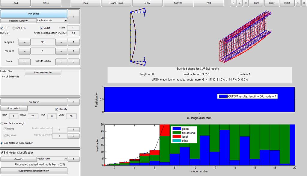
25 cfsm - constrained fininte strip method, modal decomposition and identification - Select the categories of mode base (L, G, D, O), and click on/off. You selection will be effective. You can also see the 2D or 3D figures of each mode below. - Go back to Post and click Classify. - One way to understand the result is the color distribution on the load vs. length curve. The dominant color portion (also see the numbers below the mode figure) at a the mode of certain half-wavelength corresponds with the dominant mode. 25
26 cfsm - constrained fininte strip method, modal decomposition and identification - You can also look at the load factor vs. node number curve. The will let you know the modal participation of each mode (less than the total number of eigenvalues) at a fixed half-wavelength (supplemental participation plot tells the same thing). 26
27 cfsm - constrained fininte strip method, modal decomposition and identification - Advanced users can go to cfsm page and select the mode set before submitting for analysis. This will find the buckling loads of specified modes at the halfwavelengths. An example of this is limiting the mode to G only to solve the global buckling loads of stocky members which are much higher than local buckling loads. 27
28 28
29 29
30 30
31 31
32 Boundary condition and higher modes - In fact, at a given half-wavelength in our code, there are infinite buckling modes. However, the one with the lowest critical load are most possible to happen. We only solve designated number of eigenvalues. - Constraints affect the buckling load since some buckling mode will not happen if the component is properly constrained. - CUFSM allows you to add constraints: either by adding springs at nodes or imposing equations (master-slave) as constraints. (See the front panel) 32
33 Boundary condition and higher modes - Due to the constraints, some buckling mode will not appear. However, the buckling load will point to a certain higher mode. After all, the buckling load indeed increases. This buckling load will be used if necessary in our design. - For example, after the torsion is restrained, the distortional buckling would result in a local minimum. 33
34 Conclusion This tutorial is intended to show how CUFSM4 works. You should be able to calculate the buckling load of common cross-section and recognize the critical ones with respect to their modes. You can get an idea on more advanced functions like using cfsm and adding spring or multi-pointconstraint to nodes on the section to model things like sheathing stiffness. 34
Advanced Ideas and Examples
 CUFSM 3.12 Advanced Ideas and Examples Defining buckling modes Why define buckling modes? Understanding higher modes Utilizing higher modes Handling Indistinct modes Solution Accuracy Defining Buckling
FE modeling of elastic buckling of stud walls
 FE modeling of elastic buckling of stud walls September 28 version O. Iuorio*, B.W. Schafer *This report was prepared while O. Iuorio was a Visiting Scholar with B.W. Schafer s Thin-walled Structures Group
ADAPT-PTRC 2016 Getting Started Tutorial ADAPT-PT mode
 ADAPT-PTRC 2016 Getting Started Tutorial ADAPT-PT mode Update: August 2016 Copyright ADAPT Corporation all rights reserved ADAPT-PT/RC 2016-Tutorial- 1 This ADAPT-PTRC 2016 Getting Started Tutorial is
ADAPT-PT 2010 Tutorial Idealization of Design Strip in ADAPT-PT
 ADAPT-PT 2010 Tutorial Idealization of Design Strip in ADAPT-PT Update: April 2010 Copyright ADAPT Corporation all rights reserved ADAPT-PT 2010-Tutorial- 1 Main Toolbar Menu Bar View Toolbar Structure
Introductory Questions
 CUFSM 2.5 Introductory Questions CUFSM? What is CUFSM? What are the system requirements? Why would I use CUFSM? Why do 2 versions of CUFSM exist? Why would I use the Matlab version? CUFSM is free? Finite
TABULATED LOCAL AND DISTORTIONAL ELASTIC BUCKLING SOLUTIONS FOR STANDARD SHAPES
 test TECHNICAL NOTE On Cold-Formed Steel Construction Cold-Formed Steel Engineers Institute Washington, DC www.cfsei.org 866-465-4732 $5.00 TABULATED LOCAL AND DISTORTIONAL ELASTIC BUCKLING SOLUTIONS FOR
How to model Mohr-Coulomb interaction between elements in Abaqus
 How to model Mohr-Coulomb interaction between elements in Abaqus Problem description We want to model the interaction between two masonry walls and a timber beam. The elements are connected by special
SETTLEMENTS DUE TO TUNNEL CONSTRUCTION
 5 SETTLEMENTS DUE TO TUNNEL CONSTRUCTION In this tutorial the construction of a shield tunnel in medium soft soil and the influence on a pile foundation is considered. A shield tunnel is constructed by
A Finite Element Approach to Reinforced Concrete Slab Design in GT STRUDL
 A Finite Element Approach to Reinforced Concrete Slab Design in GT STRUDL James Deaton and Dr. Kenneth M. Will 2006 GT STRUDL Users Group Meeting 23 June 2006 1 Introduction Background and Motivation The
Inside this Issue. What's New at BSI. Technical Corner. Fall, 2007 Issue #10. Welcome to the Fall issue of the BSI Newsletter!
 Fall, 2007 Issue #10 Welcome to the Fall issue of the BSI Newsletter! In this issue's Technical Corner details regarding the use of the Wind Generator with the Bridge option. In our Discussions with..
Structural Engineering and Materials
 VIRGINIA POLTECHNIC INSTITUTE AND STATE UNIVERSIT The Charles E. Via, Jr. Department of Civil and Environmental Engineering Blacksburg, VA 24061 Structural Engineering and Materials ELASTIC BUCKLING OF
Self-shape Optimisation of Cold-formed Steel Columns
 Missouri University of Science and Technology Scholars' Mine International Specialty Conference on Cold- Formed Steel Structures (2012) - 21st International Specialty Conference on Cold-Formed Steel Structures
ADAPT-PT 2010 GETTING STARTED GUIDE
 ADAPT-PT 2010 GETTING STARTED GUIDE Copyright ADAPT 2007, 2008 all rights reserved support@adaptsoft.com www.adaptsoft.com ADAPT Corporation, Redwood City, California, USA, Tel: +1 (650) 306-2400 ADAPT
ADAPT-PT 2012 GETTING STARTED GUIDE
 ADAPT-PT 2012 GETTING STARTED GUIDE Copyright ADAPT 2007, 2008,2012 all rights reserved support@adaptsoft.com www.adaptsoft.com ADAPT Corporation, Redwood City, California, USA, Tel: +1 (650) 306-2400
MASONRY INSIGHTS. Finite Element Modeling, Analysis, and Design for Masonry. Introduction
 MASONRY INSIGHTS Finite Element Modeling, Analysis, and Design for Masonry Software programs for structural engineers continue to escalate in complexity as we continue to become increasingly reliant on
Numerical Studies on the Composite Action and Buckling Behavior of Built-Up Cold-Formed Steel Columns
 Missouri University of Science and Technology Scholars' Mine International Specialty Conference on Cold- Formed Steel Structures (2014) - 22nd International Specialty Conference on Cold-Formed Steel Structures
Introduction to. Asian Center for Engineering Computations and Software. ACECOMS & AIT Solutions 1
 Introduction to 2016 Asian Center for Engineering Computations and Software ACECOMS & AIT Solutions 1 ETABS 2016 is The ultimate integrated software package for the structural analysis, design and detailing
Strip Footing - Ultimate Bearing Capacity
 Strip Footing - Ultimate Bearing Capacity analys: nonlin phase physic. constr: suppor tying. elemen: ct12e pstrai. load: deform weight. materi: consta crack cutoff elasti full harden isotro mohrco multil
ADAPT PT7 TUTORIAL FOR BEAM FRAME 1
 ADAPT PT7 TUTORIAL FOR BEAM FRAME 1 Technical Note Structural Concrete Software System TN189_PT7_tutorial_beam_frame 012705 1 BEAM FRAME The objective of this tutorial is to demonstrate the step-by-step
ETABS 2016 Tutorial: Trusses
 ETABS 2016 Tutorial: Trusses Below is a tutorial that was organized for educational purposes at Christian Brothers University only. The procedure of analysis in ETABS 2016 is similar to that of ETABS v9.
CE 160 SAP 2000 Notes for 2D Problems. Element and Joint Drawing Tools Global Coordinates of Cursor Position Units in View Window
 CE 160 SAP 2000 Notes for 2D Problems SAP 2000 Main Screen Highlights Title of View Model Lock Zoom Controls Global Coordinate Plane of View Window Pull Down Menus Element and Joint Drawing Tools Global
HILLCREST MANOR Palo Verde, California
 STRUCTURAL ENGINEERING CONSULTANTS TN358_MAT_RC_desogm_example_040110 HILLCREST MANOR Palo Verde, California Structural Design of Mat (Raft) Foundation First draft ADAPT Corporation Redwood City, CA, USA
Release Webinar. Release Date : March Product Ver. : Civil 2016 (v2.1)
") Release Webinar Release Date : March. 2016 Product Ver. : (v2.1) DESIGN OF CIVIL STRUCTURES I n t e g r a t e d S o l u t i o n S y s t e m f o r B r i d g e a n d C i v i l E n g i n e e r i n g Enhancements
Release Webinar Release Date : March. 2016 Product Ver. : (v2.1) DESIGN OF CIVIL STRUCTURES I n t e g r a t e d S o l u t i o n S y s t e m f o r B r i d g e a n d C i v i l E n g i n e e r i n g Enhancements
Local and Distortional Buckling of Cold-Formed Steel Members
 Local and Distortional Buckling of Cold-Formed Steel Members André Eduardo Martins Rua Pinto MSc Dissertation in Civil Engineering Civil Engineering and Architecture Department, Instituto Superior Técnico,
Direct Strength Design for Cold-Formed Steel Members with Perforations. We look forward to your comments regarding this ongoing research.
 August 1, 2006 To: AISI Committee Members Subject: Progress Report No. 2 Direct Strength Design for Cold-Formed Steel Members with Perforations Please find enclosed the second progress report summarizing
DYNAMIC RESPONSE ANALYSIS OF THE RAMA 9 BRIDGE EXPANSION JOINT DUE TO RUNNING VEHICLE
 DYNAMIC RESPONSE ANALYSIS OF THE RAMA 9 BRIDGE EXPANSION JOINT DUE TO RUNNING VEHICLE Tanan Chub-uppakarn 1, Adison Owatsiriwong 2* 1 Department of Civil Engineering, Faculty of Engineering, Prince of
New approach to improving distortional strength of intermediate length thin-walled open section columns
 New approach to improving distortional strength of intermediate length thin-walled open section columns R. S. Talikoti 1, K. M. Bajoria 2 1 Research Scholar (Email: rstalikoti@iitb.ac.in) 2 Associate Professor
MAE 456 FINITE ELEMENT ANALYSIS Truss Buckling Analysis LAB INSTRUCTIONS LAB ASSIGNMENT 3. Lab Objectives. Lab Tasks
 MAE 456 FINITE ELEMENT ANALYSIS Truss Buckling Analysis LAB INSTRUCTIONS LAB ASSIGNMENT 3 Lab Objectives erform a FEA Eigenvalue buckling analysis of a simple column. erform a FEA Eigenvalue buckling analysis
Longwave Buckling of Cold-formed Steel Studs Using Direct Strength
 Missouri University of Science and Technology Scholars' Mine International Specialty Conference on Cold- Formed Steel Structures (2006) - 18th International Specialty Conference on Cold-Formed Steel Structures
Analysis of Sheathed Cold-Formed Steel Wall Studs
 Sixteenth International Specialty Conference on Cold-Formed Steel Structures Orlando, Florida U.S.A., October 17-18, 2002 Analysis of Sheathed Cold-Formed Steel Wall Studs Benjamin W. Schafer 1, Badri
Analysis of Sheathed Cold-Formed Steel Wall Studs
 Abstract Sixteenth International Specialty Conference on Cold-Formed Steel Structures Orlando, Florida U.S.A., October 17-18, 2002 Analysis of Sheathed Cold-Formed Steel Wall Studs Benjamin W. Schafer
ADAPT PT7 TUTORIAL FOR ONE-WAY SLAB 1
 Structural Concrete Software System TN187_PT7_tutorial_one_way_slab 012705 ADAPT PT7 TUTORIAL FOR ONE-WAY SLAB 1 1. ONE-WAY SLAB SUPPORTED ON BEAMS The objective of this tutorial is to demonstrate the
GEO-SLOPE International Ltd, Calgary, Alberta, Canada Tie-back Wall
 1 Introduction Tie-back Wall This example simulates the sequential construction of a sheet-pile shoring wall tied back with pre-stressed anchors. The purpose is to demonstrate the steps involved in modeling
Unwedge v Tutorial 3 Perimeter Support. Topics Covered:
 Unwedge v. 4.0 Tutorial 3 Perimeter Support Topics Covered: Perimeter support design view Wedge apex height Adding a bolt pattern Bolt properties Editing a bolt pattern Bolt data tips Bolt support force
CHAPTER 6 FINITE ELEMENT ANALYSIS
 105 CHAPTER 6 FINITE ELEMENT ANALYSIS 6.1 INTRODUCTION Several theoretical approaches are considered to analyze the yielding and buckling failure modes of castellated beams. Elastic Finite Element Analysis
SAFE 2016 (v16.0.0) Release Notes
 Release Notes") SAFE 2016 (v16.0.0) Release Notes Copyright Computers and Structures, Inc., 2016 Notice Date: 2016-12-22 This file lists all changes made to SAFE since the previous version. Incidents marked with an asterisk
SAFE 2016 (v16.0.0) Release Notes Copyright Computers and Structures, Inc., 2016 Notice Date: 2016-12-22 This file lists all changes made to SAFE since the previous version. Incidents marked with an asterisk
Shrinkage Effects on a Concrete Slab on Ground
 Shrinkage Effects on a Concrete Slab on Ground Outline 1 Description 2 Finite Element Model 2.1 Units 2.2 Geometry Definition 2.3 Properties 2.3.1 Concrete slab 2.3.2 Grid reinforcement 2.3.3 Soil interface
Modeling Component Assembly of a Bearing Using Abaqus
 Modeling Component Assembly of a Bearing Using Abaqus Bisen Lin, Ph.D., P.E. and Michael W. Guillot, Ph.D., P.E. Stress Engineering Services, Inc. Abstract: Assembly process of a bearing considered in
Distortional elastic buckling for aluminium: Available prediction models versus design specifications
 Distortional elastic buckling for aluminium: Available prediction models versus design specifications. Kutanova Eindhoven University of Technology, the etherlands T. Peköz Cornell University, USA F. Soetens
Dynamic Structural Analysis Suite (DSAS) User Manual
 User Manual") CIPPS TR-002-2012 Dynamic Structural Analysis Suite (DSAS) User Manual Version 4 Serdar Astarlioglu and Ted Krauthammer March 2012 Acknowledgements The Center for Infrastructure Protection and Physical
CIPPS TR-002-2012 Dynamic Structural Analysis Suite (DSAS) User Manual Version 4 Serdar Astarlioglu and Ted Krauthammer March 2012 Acknowledgements The Center for Infrastructure Protection and Physical
Modal-spectral analysis of a gas storage tank.
 Modal-spectral analysis of a gas storage tank. Description of the structure: A Spherical tank gas storage is formed by: 1.- S-355 steel sphere plate elements of 1.5 cm thickness. 2.- Eight vertical posts
DDBA8437: Central Tendency and Variability Video Podcast Transcript
 DDBA8437: Central Tendency and Variability Video Podcast Transcript JENNIFER ANN MORROW: Today's demonstration will review measures of central tendency and variability. My name is Dr. Jennifer Ann Morrow.
Modeling and Design of Bridge Super Structure and Sub Structure
 Topic 3 Day 2 Modeling and Design of Bridge Super Structure and Sub Structure Naveed Anwar 1. Over view of Bridge Design Process and Bridge Types 2. Advances and recent trends in Modeling and Analysis
Structural Engineering, Mechanics, and Materials. Preliminary Exam - Structural Design
 Fall Semester 2018 Preliminary Exam - Structural Design A small building is located in downtown Berkeley. The structural system, either structural steel or reinforced concrete, comprises gravity framing
P A (1.1) load or stress. elongation or strain
 load or stress. elongation or strain") load or stress MEEN 3145 TENSION TEST - BACKGROUND The tension test is the most important and commonly used test in characterizing properties of engineering materials. This test gives information essential
load or stress MEEN 3145 TENSION TEST - BACKGROUND The tension test is the most important and commonly used test in characterizing properties of engineering materials. This test gives information essential
Example Application 10. Analysis of a Concrete Diaphragm Wall
 Example Application 10 Analysis of a Concrete Diaphragm Wall 1 Cross section through diaphragm wall 2 Soil Properties Excavation and Dewatering Depths 3 Strut Properties 4 Modeling Procedure Step 1 Step
SEISMIC BEHAVIOR OF STEEL RIGID FRAME WITH IMPERFECT BRACE MEMBERS
 INTERNATIONAL JOURNAL OF CIVIL ENGINEERING AND TECHNOLOGY (IJCIET) International Journal of Civil Engineering and Technology (IJCIET), ISSN 976 638 (Print), ISSN 976 6316(Online), Volume 6, Issue 1, January
Effective Width Method Based Design for Distortional Buckling
 Missouri University of Science and Technology Scholars' Mine International Specialty Conference on Cold- Formed Steel Structures (2006) - 18th International Specialty Conference on Cold-Formed Steel Structures
S T R U C T U R. magazine. Direct Strength Method for Cold-Formed Steel. Copyright. What are the Advantages in Using Direct Strength Method?
 Direct Strength ethod for Cold-Formed Steel By Helen Chen, h.d.,.e., Benjamin Schafer, h.d.,.e., and Roger LaBoube, h.d.,.e. In 2004, The North American Specification for the Design of Cold- Formed Steel
Buckling Analysis of Cold Formed Steel for Beams
 International Journal of Scientific and Research Publications, Volume 5, Issue 5, May 2015 1 Buckling Analysis of Cold Formed Steel for Beams Prakash M. Mohite *, Aakash C. Karoo ** * Associate Professor,
Fz LLC. Exclusive Distributor in the Middle East for CSI Software licensing, technical support and training solutions
 Exclusive Distributor in the Middle East for CSI Software licensing, technical support and training solutions www.techiesoft.com For Sales: sales@techiesoft.com For Technical Support: support@techiesoft.com
STUDY ON THE EFFECT OF SPACERS ON THE ULTIMATE CAPACITY OF INTERMEDIATE LENGTH THIN WALLED SECTION UNDER COMPRESSION *
 IJST, Transactions of Civil Engineering, Vol. 38, No. C1 +, pp 191-204 Printed in The Islamic Republic of Iran, 2014 Shiraz University STUDY ON THE EFFECT OF SPACERS ON THE ULTIMATE CAPACITY OF INTERMEDIATE
Question Paper Code : 11410
 Reg. No. : Question Paper Code : 11410 B.E./B.Tech. DEGREE EXAMINATION, APRIL/MAY 2011 Fourth Semester Mechanical Engineering ME 2254 STRENGTH OF MATERIALS (Common to Automobile Engineering and Production
COURSE ON COMPUTATIONAL GEOTECHNICS A Geotechnical Design Tool. Faculty of Civil Engineering UiTM, Malaysia
 COURSE ON COMPUTATIONAL GEOTECHNICS A Geotechnical Design Tool Faculty of Civil Engineering, Malaysia Name : COURSE CONTENTS Use of Plaxis Getting Started Exercise 1: Elastic analysis of drained footing
Tekla Structural Designer 2016
 Tekla Structural Designer 2016 Reference Guides (AS Non-Composite Steel) April 2016 2016 Trimble Solutions Corporation part of Trimble Navigation Ltd. Table of Contents Loading - Australian Standards...
Experiment on Precast Solid Concrete Floor Slabs resting on Cold- Formed Steel Framing Stud Walls
 Experiment on Precast Solid Concrete Floor Slabs resting on Cold- Formed Steel Framing Stud Walls Watanapong Hiranman 1) and Nuthaporn Nuttayasakul 2) 1) Department of Civil Engineering, Mahanakorn University
Local and Distortional Buckling of Cold-formed Steel Studs
 Missouri University of Science and Technology Scholars' Mine International Specialty Conference on Cold- Formed Steel Structures (2006) - 18th International Specialty Conference on Cold-Formed Steel Structures
STT+ Single-span Steel Beam. FRILO Software GmbH As of 04/07/2016
 STT+ Single-span Steel Beam FRILO Software GmbH www.frilo.com info@frilo.com As of 04/07/2016 STT+ STT+ Single-span Steel Beam Contents Application options 4 Basis of calculation 6 Design values of the
GEO-SLOPE International Ltd, Calgary, Alberta, Canada Tie-back Wall
 1 Introduction Tie-back Wall This example simulates the sequential construction of a sheet-pile shoring wall tied back with pre-stressed anchors. The purpose is to demonstrate the steps involved in modeling
Buckling Analysis of Cold Formed Steel Compression Members at Elevated Temperatures
 International OPEN ACCESS Journal Of Modern Engineering Research (IJMER) Buckling Analysis of Cold Formed Steel Compression Members at Elevated Temperatures A.A.Patil 1, J.G. Solanki 2 1 M.tech Student,
Example Application 11. Multistage Tunnel Excavation and Support
 Example Application 11 Multistage Tunnel Excavation and Support 1 Multi-Stage Tunnel Construction 2 Multistage Tunnel Conditions Rock Mass Properties Mohr-Coulomb Model unit weight 27,000 N/m 3 bulk modulus
(a) Pin-Pin P cr = (b) Fixed-Fixed P cr = (d) Fixed-Pin P cr =
 Pin-Pin P cr = (b) Fixed-Fixed P cr = (d) Fixed-Pin P cr =") 1. The most critical consideration in the design of rolled steel columns carrying axial loads is the (a) Percent elongation at yield and the net cross-sectional area (b) Critical bending strength and axial
1. The most critical consideration in the design of rolled steel columns carrying axial loads is the (a) Percent elongation at yield and the net cross-sectional area (b) Critical bending strength and axial
The SP Suite has the capability to design an entire concrete structure from foundation to roof. These programs are based on the methods, equations,
 StructurePoint is a software company that provides concrete design solutions. Formerly the engineering software group of the Portland Cement Association (PCA), StructurePoint (SP) is located in Chicago
Release Notes for RISA-3D Version 6.0
 Release Notes for RISA-3D Version 6.0 Version 6.0 Enhancements / Corrections Enhanced Wood Design Features Added Glu-Lam design per 2001 NDS Enhanced Concrete Design Features Added user defined reinforcement
ACCURATE LINEAR AND NONLINEAR SEISMIC SSI ANALYSIS BASED ON ANSYS FE MODELING USING EXTENDED SASSI METHODOLOGY
 Transactions, SMiRT-24 II, Paper 468 ACCURATE LINEAR AND NONLINEAR SEISMIC SSI ANALYSIS BASED ON ANSYS FE MODELING USING EXTENDED SASSI METHODOLOGY Dan M. Ghiocel 1, Mike Saremi 2 1 Chief of Engineering
Release Notes for RISA-3D 8.1.0
 Release Notes for RISA-3D 8.1.0 Version 8.1.0 Enhancements/Corrections Enhancements Added the ability to model wood shear walls with openings, incorporating three design options: segmented, perforated
STS+ Single-span Steel Column. FRILO Software GmbH Version 2/2017 As of 07/11/2017
 STS+ Single-span Steel Column FRILO Software GmbH www.frilo.com info@frilo.com Version 2/2017 As of 07/11/2017 STS+ Frilo Application: STS+ Single-span Steel Column Contents Application options 4 Basis
ELASTIC AND ELASTO-PLASTIC BUCKLING ANALYSIS OF PERFORATED STEEL PLATES
 ELASTIC AND ELASTO-PLASTIC BUCKLING ANALYSIS OF PERFORATED STEEL PLATES MAURO DE VASCONCELLOS REAL 1, LIÉRCIO ANDRÉ ISOLDI 2, ALEXANDRA PINTO DAMAS 3, DANIEL HELBIG 4 ABSTRACT Many steel structures such
This is a repository copy of Cross-sectional optimization of cold-formed steel channels to Eurocode 3.
 This is a repository copy of Cross-sectional optimization of cold-formed steel channels to Eurocode 3. White Rose Research Online URL for this paper: http://eprints.whiterose.ac.uk/89220/ Version: Accepted
SIMPLE INVESTIGATIONS OF TENSILE MEMBRANE ACTION IN COMPOSITE SLABS IN FIRE
 SIMPLE INVESTIGATIONS OF TENSILE MEMBRANE ACTION IN COMPOSITE SLABS IN FIRE By Ahmed Allam 1, Ian Burgess 1 and Roger Plank 1 Department of Civil and Structural Engineering, University of Sheffield, UK
Research Article Numerical Analysis of Eccentrically Loaded Cold-Formed Plain Channel Columns
 Journal of Structures, Article ID 908415, 10 pages http://dx.doi.org/10.1155/2014/908415 Research Article Numerical Analysis of Eccentrically Loaded Cold-Formed Plain Channel Columns A. P. Nivethitha,
GUSSET PLATES IN RAILROAD TRUSS BRIDGES FINITE ELEMENT ANALYSIS AND COMPARISON WITH WHITMORE TESTING
 GUSSET PLATES IN RAILROAD TRUSS BRIDGES FINITE ELEMENT ANALYSIS AND COMPARISON WITH WHITMORE TESTING Walid S. Najjar, Ph.D., P.E. 1, Frank DeOrtentiis, P.E. WSP SELLS 555 Pleasantville Road, Briarcliff
Customizable and Integrated Configuration. Modeling Environment. Advanced Meshing Tools
 Model, analyze and design structures regardless of geometric complexity, material type, loading conditions, nonlinear effects, or design codes. Easy enough for simple projects, powerful enough for the
Multiframe Steel Codes
 Multiframe Steel Codes Windows Version 16 User Manual Bentley Systems, Incorporated 2013 License & Copyright Multiframe Steel Codes software & User Manual 2013 Bentley Systems, Incorporated iii Table
ATENA Program Documentation Part 4-8
 Červenka Consulting s.r.o. Na Hrebenkach 55 150 00 Prague Czech Republic Phone: +420 220 610 018 E-mail: cervenka@cervenka.cz Web: http://www.cervenka.cz ATENA Program Documentation Part 4-8 ATENA Science
COMPARATIVE REPORT CYPECAD VS. ETABS
 COMPARATIVE REPORT CYPECAD VS. ETABS Contents SIMPLE FRAME EXAMPLE... 3 1. Introduction... 4 2. Dimensions and applied loads... 4 3. Materials and applied design code... 5 4. Nodes... 7 5. Moment and shear
COMPUTERS AND STRUCTURES, INC., AUGUST 2010 PRACTICAL HOW-TO GUIDE TECHNICAL NOTE 2005 AISC DIRECT ANALYSIS METHOD
 COMPUTERS AND STRUCTURES, INC., AUGUST 2010 PRACTICAL HOW-TO GUIDE TECHNICAL NOTE 2005 AISC DIRECT ANALYSIS METHOD This is a practical how-to guide for using the (DAM) in SAP2000, ETABS, and CSiBridge
Supplementary Figures
 Supplementary Figures Supplementary Figure 1. (a) Transmittance spectra of the TCM at different strains as tested before the fatigue test; (b) correlation between cyclic stress and cycles curve for the
Analysis of Shear Wall Transfer Beam Structure LEI KA HOU
 Analysis of Shear Wall Transfer Beam Structure by LEI KA HOU Final Year Project report submitted in partial fulfillment of the requirement of the Degree of Bachelor of Science in Civil Engineering 2013-2014
1. Stress Analysis of a Cantilever Steel Beam
 . Stress Analysis of a Cantilever Steel Beam Applicable CivilFEM Product: All CivilFEM Products Level of Difficulty: Easy Interactive Time Required: 5-0 minutes Discipline: Structural Steel Analysis Type:
The University of Sydney School of Civil Engineering Centre for Advanced Structural Engineering NSW 2006 Australia. SupaPurlin
 The University of Sydney School of Civil Engineering Centre for Advanced Structural Engineering NSW 2006 Australia SupaPurlin Analysis and Design of Supa Purlins According to AS/NZS 4600:2005 PURLIN Analysis
Nonlinear Finite Element Analysis of Composite Cantilever Beam with External Prestressing
 Nonlinear Finite Element Analysis of Composite Cantilever Beam with External Prestressing R. I. Liban, N. Tayşi 1 Abstract This paper deals with a nonlinear finite element analysis to examine the behavior
Software Verification
 METHODOLOGY A comprehensive series of test problems, or examples, designed to test the various elements, analysis features, and design algorithms of the program were created. The results produced by were
CHAPTER 6 PLASTIC ZONE SIZE
 96 CHAPTER 6 PLASTIC ZONE SIZE This chapter elaborates on conventional methods and finite element methods to evaluate the plastic zone size at failure. An elastic-plastic finite element analysis procedure
CHAPTER 5 FINITE ELEMENT MODELLING
 53 CHAPTER 5 FINITE ELEMENT MODELLING 5.1 GENERAL Reinforced concrete structures are largely employed in engineering practice in a variety of situations and applications. In most cases these structures
ShipRight Design and Construction
 ShipRight Design and Construction Additional Design Procedures Assessment of Steel Hatch Covers Using Finite Element Analysis January 2018 Working together for a safer world Document History Document Date:
UTrAp 2.0. Analysis of Steel Box Girders during Construction. developed at. The University of Texas at Austin
 UTrAp 2.0 Analysis of Steel Box Girders during Construction developed at The University of Texas at Austin by Eric Williamson Cem Topkaya Daniel Popp Joseph Yura October 2004 UTrAp 2.0 User s Guide UTrAp
Precast Concrete Bearing Wall Panel Design (Alternative Analysis Method) (Using ACI )
 (Using ACI )") Precast Concrete Bearing Wall Panel Design (Alternative Analysis ethod) (Using ACI 318-14) Precast Concrete Bearing Wall Panel Design (Alternative Analysis ethod) (Using ACI 318-14) A structural precast
Precast Concrete Bearing Wall Panel Design (Alternative Analysis ethod) (Using ACI 318-14) Precast Concrete Bearing Wall Panel Design (Alternative Analysis ethod) (Using ACI 318-14) A structural precast
US Composites User Guide and Theoretical Background
 US Composites User Guide and Theoretical Background US Composites User Guide and Theoretical Background All information in this document is subject to modification without prior notice. No part of this
Bond-slip of Post-tensioned Reinforcement in 2D elements
 Y X Bond-slip of Post-tensioned Reinforcement in 2D elements ANALYS keywords: nonlin phase physic CLASS keywords: large CONSTR keywords: suppor tying ELEMEN keywords: bar bondsl cable cl6tr cq16m cq22if
Tekla Structural Designer 2017
 Tekla Structural Designer 2017 Engineer s Handbooks (AS) March 2017 (5.0.0.7) 2017 Trimble Solutions Corporation part of Trimble Navigation Ltd. Table of Contents Wind Modeling Handbook... 1 Application
KINETICS Pipe & Duct Seismic Application Manual
 S8.1 Introduction: During an earthquake, the hanger rods are not passive components that just simply support the dead load of the pipe or duct. They must also resist the reaction forces generated by the
COMPARISON OF MULTISTORY WALL RESULTS BETWEEN ADAPT-EDGE 1 AND ETABS 2 CONCRETE FRAME WITH SHEARWALLS
 Your Partner in Structural Concrete Design TN500_EDGE_Etabs_Comp_06132016 COMPARISON OF MULTISTORY WALL RESULTS BETWEEN ADAPT-EDGE 1 AND ETABS 2 CONCRETE FRAME WITH SHEARWALLS INTRODUCTION This Technical
OPTIMIZATION OF AN AXIALLY COMPRESSED RING AND STRINGER STIFFENED CYLINDRICAL SHELL WITH A GENERAL BUCKLING MODAL IMPERFECTION
 From: AIAA 48th Structures, Structural Dynamics, and Materials Conference, Paper no. AIAA-2007-2216, 2007 OPTIMIZATION OF AN AXIALLY COMPRESSED RING AND STRINGER STIFFENED CYLINDRICAL SHELL WITH A GENERAL
Transactions, SMiRT-22 San Francisco, California, USA - August 18-23, 2013 Division V
 Transactions, SMiRT- San Francisco, California, USA - August 8-, SIMPLIFIED MODELING OF EFFECTS OF CONCRETE CRACKING ON OUT-OF-PLANE VIBRATIONS OF FLOORS Luben Todorovski, Mahmoud Khoncarly, Dan M Ghiocel,
SAP2000 Overview One Window, Many Views
 Exclusive Distributor in the Middle East for CSI Software licensing, technical support and training solutions www.techiesoft.com For Sales: sales@techiesoft.com For Technical Support: support@techiesoft.com
Software Verification
 EXAMPLE 9 ACI Handbook Two-Way Slab Example 2 PROBLEM DESCRIPTION The two-way slab system arranged three-by-three is shown in Figure 9-1. The slab consists of nine 6.5-inch-thick 20-foot 24-foot panels.
OPTUM COMPUTATIONAL ENGINEERING FEATURES
 OPTUM COMPUTATIONAL ENGINEERING FEATURES Version 2016 OptumG2: Features K Krabbenhoft, AV Lymain, J Krabbenhoft (Editors) c Optum Computational Engineering 2016 www.optumce.com CONTENTS Contents 1 GENERAL
APPENDIX A - SIZING OF BRIDGE AND SUPPORT SYSTEM
 APPENDIX A - SIZING OF BRIDGE AND SUPPORT SYSTEM Steel Bridge Selection of Type of Steel Bridge Acrow Bridge From the personal communication with Acrow bridges regional office in Colorado (Needham, Randy),