SHORING SYSTEMS FROM SHORING PROFESSIONALS
|
|
|
- Lindsay Dennis
- 6 years ago
- Views:
Transcription


1 MANUAL STANDARD-BOX VB 100 Klosterhofweg 62 Tel: Site: GmbH D Mönchengladbach-Güdderath Fax: Mail: TRENCH SHORING SYSTEMS FROM SHORING PROFESSIONALS
 of the strut type.")
 or 120 mm plate thickness at a length of 4,000 or 5,000 mm Optimal stability means it")
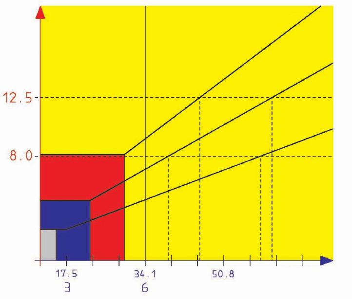
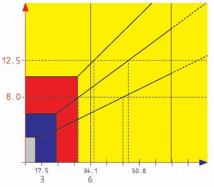
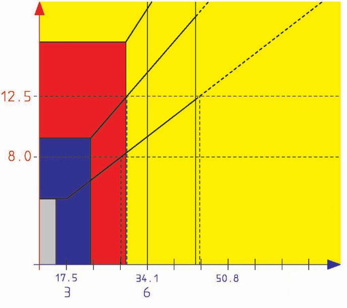
2 These instructions for use must be presented to the building site personnel. The diagram relating to the stress on the lower strut must be observed, as well as the load capacity diagram (characteristic stress curve) of the strut type. With the strut stress determined from the stress diagram, it must be checked on the load capacity diagram for the strut whether it is possible to use the required trench width. 1. General purpose of use Edge-supported shoring box with a plate thickness of 105 mm (up to 3,500 mm plate length) or 120 mm plate thickness at a length of 4,000 or 5,000 mm Optimal stability means it is best suited for installation in the lowering procedure. 2. Specifications Box length : 2000/2500/3000/3500/4000/5000 mm Box height of baseplate : 2.600/2.400 mm Max. pipe culvert height : 1.555/1.355 mm Box height, support plate : mm Strut type : SP SB 98 x 700/500/392 or Safety regulations WARNING We refer to the fact that the above shoring system is only for the intended use and may only be assembled, installed, dismantled and unmounted in the sequence listed under points 4-7, exclusively with the use of all relevant "original construction elements". Please ensure a steady installation of the box; otherwise, it should be changed if necessary! If this is not observed, the manufacturer's liability and warranty are invalid. Observe the load-bearing capacity of the shoring elements. Note: All of the requirements of BG-Bau (the professional association) as well as DIN 4124 Excavations and trenches, embankments, work - room widths, shoring are applicable. In the event of conditions deviating from the standard conditions, construction site statics must be prepared. 4. Assembly: a) Lay the plate (1) with the soldier profiles (2) facing upwards on level ground. b) Insert four pretensioned mushrooms (3) into the guide profiles of the soldier profiles. Insert the corresponding bolts (4) d = 43 mm, L = 212 mm into the mounting holes provided on the soldier profiles and secure them with safety clips. Detension the mushrooms by loosening the nuts (5). Note: Two mushrooms with a strut (6) and possibly a extension pipe (7) form one strut unit. c) Insert the strut (6) into the spring caps. Insert the bolt (8) d = 20 mm, L = 140 mm and secure with cotter pins. d) If necessary, i.e. according to the trench width, only one Extension pipe(7) may be used for each strut unit. The extension pipe must not be longer than 3.00 m. For static reasons, the struts are mounted alternately staggered (Fig. 1), attached with bolts (9) d = 20 mm, L = 140 mm and safety clips. e) Attach the second plate (10) equipped with mushrooms onto the mounted strut/widening tubes and bolt and secure with safety clips pins as described above. f) Using a strut wrench on the struts, increase the lower distance of the plates by 4-5 cm (Fig. 2). Image 1a Image 1b 2


3 5. Installation 5.1 Installation procedure for solid ground Pick up the first preassembled shoring box using an appropriate hoisting device and place it in the previously raised ditch section. The weights can be taken from the datasheets, as mentioned above. Then, by turning the shafts with the shaft wrench, press the plates against the ditch walls. 5.2 Lowering procedure for unsolid ground a) Protect the plates of the VB 100 against damage before insertion by the excavator by attaching the pressure rails (13) to them. The shoring unit is pressed in the area of the post. The max. distance "B" per insertion procedure is shown in Fig. 2. For example, a ditch width "A" of 300 cm results in a distance "B" of 37 cm. If the distance "B" is greater than that shown in Fig. 2, individual components of the shoring unit may become damaged. Pre-excavate the ditch to a max. depth of 1.25 m. b) Lift the preassembled shoring unit set to the ditch width with an appropriate hoisting device and place it in the pre-excavated ditch. Refer again to the datasheets to find the weights. c) Excavate approx m alternately and press down the plates by the distance "B" (see Fig. 2). d) If the ditch depth exceeds the box height, then the shoring depth can be increased if necessary with the support boxes (Fig. 3). These are connected to the guide posts with connecting rings (14) via locking pins (4) d = 43 mm and secured with cotter pins. Now excavate and press down again, as described in 5.2 c). B: Max. Plattemvorlauf in cm Image 2 Max. Plattenvorlauf bezogen auf die Grabenbreite Grabenbreite in cm Image 3 3
4 6. Dismantling 6.1 Dismantling in setting procedures a) Loosen the plates pressed against the ditch wall (see 5.1) by turning the struts away from the ditch wall. b) Insert the backfilling material in layers (observing the compaction level). c) Pull the entire shoring unit up to the filled height. d) Compact the back filling material. e) Restart at point 6.1.b, until the VB 100 is completely pulled out of the earth. 6.2 Dismantling in the lowering procedure a) Insert the back filling material in layers (observing the compaction level). b) Pull out the VB 100 up to the filled area. The height of the respective individual pass "B" is according to Fig. 2. c) Compact the back filling material. d) Restart at point 6.2.a, until the VB 100 is completely pulled out of the earth. 7. Disassembly Before transporting away the VB 100, it is disassembled analogously to the assembly but in the reverse sequence. 8. Maintenance / Service On each disassembly, the VB 100 should be cleaned. The free strut ends must be cleaned and kept in a well-lubricated state. The entire shoring unit must be protected against corrosion caused by handling damage by the use of appropriate protective measures. 9. Transport When unloading, you should store the supplied wooden blocks and the rubber plates appropriately. These parts must always be re-used for the return transport. As the shipper, you are co-responsible for the appropriate shipping of the return transport. 10. Lifting and pulling Lifting, transporting, pulling or towing are only permitted with an appropriate and approved lifting accessory. Use a loading hook with a safety latch. Transport as close to the ground as possible. Only place on level, solid ground. Standing underneath hanging loads is prohibited. Standing in the machine area is prohibited. 11. Criteria for removing parts from service and repair instructions a) As a matter of principle, all shoring parts must be checked for functionality before use. b) The criteria for the removal from service of worn or damaged parts include: 1 missing parts, such as nuts, screws, rungs and bolts 2 broken parts, such as shafts, bolts, spreading systems 3 With regard to strongly deformed or twisted parts, or holes in the plate body, for example, the manufacturer should be consulted in case of doubt. c) Defective parts must be replaced or repaired. d) Smaller repairs may be performed by the user, after consultation with the manufacturer. e) Only original manufacturer spare parts may be used. f) There is no warranty for improperly performed repairs or the use of non-original parts. g) The requirements of the Operating Safety Ordinance are applicable. 4

5 12. Deflection according to DIN EN The calculated deflection applies to maximum load at the identified point. 13. Dimensioning of the pendant Diagram for selecting the lifting accessory (pendant). The vertical axis indicates the tractive force in to and the horizontal axis indicates the earth pressure in kn/m 2. (Depth of use according to standard BG example: Ditch depth < m kn/m²) Dimensioning of the pendant: Required payload of the pendant = Eah x l x h x μ x 0.05/ sin [to] Eah = Earth pressure l = plate length h = plate height μ = friction coefficient ( ) = try-square of the pendant The values in the diagram are dimensioned with æ=0.5. In the case of loose (or dry) soil, the indicated values can be more than halved accordingly. D C Shoring plate Deflection f [mm] VB x VB x VB x VB x VB x VB x VB x /2 1 5
6 VB x2600/1300 VB x2600/1300 6

7 VB x2600/1300 VB x2600/1300 7


8 2012 EUROVERBAU Die hier veröffentlichten Inhalte sind urheberrechtlich geschützt. Der Inhalt darf ohne schriftliche Genehmigung der Herausgeber weder bearbeitet, übersetzt, vervielfältigt oder verbreitet werden. 2012A MANUALSTANDARD-BOX VB 100 VB x2600/1300 VB x2600/1300 pendant length l > 3,20m Manufacturer Certification in Compliance with DIN : B 8
ASSEMBLY AND OPERATING MANUAL LTW SHORING BOXES VB 100
 Dealer: MV Trench Support Ltd Letham Road Houston Industrial Estate Livingston EH54 5BY Phone: +44 (0) 1506 / 445800 Fax: +44 (0) 1506 / 443080 Mobile: +44 (0) 7917 / 208767 MV Trench Support Ltd * Letham
ASSEMBLY AND OPERATING MANUAL LTW SLIDE RAIL SYSTEM - Type FP
 Manufacturer: LTW Tiefbauvertriebs GmbH Holter Weg 11 D 41836 Hückelhoven-Brachelen Phone: +49 (0) 24 62 / 2009 0 Fax: +49 (0) 24 62 / 2009 15 e-mail: info@ltw-verbau.de homepage: http:\ \ www.ltw-shoring.com
ASSEMBLY AND OPERATING MANUAL LTW SLIDE RAIL SYSTEM - Type PV
 Manufacturer: LTW Tiefbauvertriebs GmbH Holter Weg 11 D 41836 Hückelhoven-Brachelen Phone: +49 (0) 24 62 / 2009 0 Fax: +49 (0) 24 62 / 2009 15 e-mail: info@ltw-verbau.de homepage: http:\ \ www.ltw-shoring.com
ASSEMBLY AND OPERATING MANUAL LTW EG CORNER - MANHOLE
 Manufacturer: LTW Tiefbauvertriebs GmbH Holter Weg 11 D 41836 Hückelhoven-Brachelen Phone: +49 (0) 24 62 / 2009 0 Fax: +49 (0) 24 62 / 2009 15 e-mail: info@ltw-verbau.de homepage: http:\ \ www.ltw-shoring.com
manufacturer: 6%+7LHIEDXWHFKQLN*PE+ Ferdinand-Porsche-Str. 8 D HEINSBERG
 67$1'$5'%2;6HULHV 23(5$7,1*0$18(/ 67$1'$5'%2;6HULHV manufacturer: 6%+7LHIEDXWHFKQLN*PE+ Ferdinand-Porsche-Str. 8 D 52525 HEINSBERG phone: +49 (0) 24 52 / 91 04 0 fax: +49 (0) 24 52 / 91 04 50 e-mail: info@sbh-tiefbautechnik.com
DOUBLE SLIDE RAIL INSTALLATION METHOD. Double Slide Rail August
 Double Slide Rail August 2015 1 DOUBLE SLIDE RAIL INSTALLATION METHOD Introduction Slide rail shoring systems can be used for trenches up to 12m wide and 6m deep. Module length is determined by panels
 Instruction Manual Span Scaffolds! W A R N I N G! Before using Instant UpRight Scaffolds, read, understand and follow all Safety Rules, Erection Instructions and Maintenance Rules. Keep this manual for
Instruction Manual Span Scaffolds
 Instruction Manual Span Scaffolds QUALITY & STRENGTH YOU CAN TRUST! W A R N I N G! Before using Instant UpRight Scaffolds, read, understand and follow all Safety Rules, Erection Instructions and Maintenance
Edge Support Trench Lining System
 User Guide Conquip Trench Box Edge Support Trench Lining System Introduction The Conquip 3.5m Trench Box is a simple to assemble, two sided trench lining support system designed to be installed by an excavator
Rolling Towers. Layher Rolling Towers Uni Wide. Safety Structure Instructions for Assembly and Use. Mobile working platforms to DIN EN 1004:
 Layher Rolling Towers Uni Wide Safety Structure Instructions for Assembly and Use Mobile working platforms to DIN EN 1004:2005-03 Working platform 1.5 x 2.85 m Rolling Towers max. working height: indoors
ABACO LITTLE GIANTLIFTER
 ABACO MACHINES OPERATION MANUAL ABACO LITTLE GIANTLIFTER ABACO MACHINES USA, INC. (EAST COAST OPERATION) ABACO MACHINES USA, INC. (WEST COAST OPERATION) ABACO MACHINES INTERNATIONAL 505 Edwards Court Newport
KS - Assembly and operating manual Trench box
 Summary Technical data Montage Implementation Extraction Cinematic p4 p7 p9 p12 p13 KRINGS INTERNATIONAL FRANCE - KS - Your Trench Shoring equipment is a monoblock box system, KS type (KS60 or KS100 according
OPERATION MANUAL BISON LIFTER (ABL150)
") ABACO MACHINES OPERATION MANUAL BISON LIFTER (ABL150) ABACO MACHINES (USA) 14508 S. Garfield Ave., Paramount, CA 90723, USA Tel : 310-532-0366 Fax : 310-532-0499 Email : sales@abacomachines.com Website
ABACO MACHINES OPERATION MANUAL BISON LIFTER (ABL150) ABACO MACHINES (USA) 14508 S. Garfield Ave., Paramount, CA 90723, USA Tel : 310-532-0366 Fax : 310-532-0499 Email : sales@abacomachines.com Website
KEEP FOR FUTURE REFERENCE MRT FORKLIFT ADAPTER READ ALL INSTRUCTIONS AND WARNINGS BEFORE USING THIS PRODUCT
 KEEP FOR FUTURE REFERENCE P.O. Box 368 908 West Main Laurel, MT USA 59044 phone 800-548-7341 phone 406-628-8231 fax 406-628-8354 INSTRUCTIONS International Version STOCK NUMBER: 95722 MRT FORKLIFT ADAPTER
h Installation Manual
 h Installation Manual 1 General Information The installation of HOBAS GRP Pipes is subject to applicable standards and guidelines such as EN 1610 and ISO/ TS 10465-1. Correct installation always requires
CIRCULAR COLUMN SK 100
 CIRCULAR COLUMN SK 100 www.variant-factory.eu 1 2 VARIANT FACTORY LTD. CIRCULAR COLUMN SK 100 Contents GENERAL INSTRUCTIONS.....................................................................................
July Climbing Scaffold with retractable formwork Instructions for erection and use
 July 2008 Climbing Scaffold with retractable formwork Instructions for erection and use Contents Page Important remarks 2 Product features 2 Overview of climbing system Components 4 11 Assembly 25 Climbing
Conergy SolarFamulus II
 Conergy SolarFamulus II Installation manual www.conergy.com Table of Contents Table of Contents SolarFamulus II for universal use on flat roofs 1 Introduction 1 1.1 Short description 1 1.2 Intended use
Summary. Mini KKP - Assembly and operating manuel Pile guide box. Montage. Implementation. Accessories. Technical data
 Summary Technical data Montage Implementation Accessories p3 p5 p6 p7 KRINGS INTERNATIONAL FRANCE - Mini KKP - 1 Conformité DIN 4124 DIN EN 13331 H L L c b C0 b CU b t pl Plate height Plate length Pipe
Rolling Towers. Layher Uni Light Tower Instructions for Assembly and Use. Mobile working platforms according to DIN EN 1004:
 Instructions for ssembly and Use Mobile working platforms according to DIN EN 00:00-03 Working platform 0.7 x.8 m max. working height: indoors.3 m outdoors.3 m Rolling Towers Load bearing capacity.0 kn/m
Pallet Jack 4,400 Lbs Capacity Model #31001
 SKU # 217-0162 Pallet Jack 4,400 Lbs Capacity Model #31001 Owner s Manual and Assembly Instructions Questions? Problems? DO NOT RETURN TO STORE Please call our customer help line: (888) 315-3080 M-F 8-5
ALUMINUM SCAFFOLDING
 ALUMINUM SCAFFOLDING WARNING: IMPORTANT SAFETY RULES Do not permit anyone to use scaffolds unless he has read and is familiar with these important safety rules. SPECIAL PRECAUTIONS 1. Lock all caster brakes
Mounting systems for solar technology
 Mounting systems for solar technology ASSEMBLY INSTRUCTIONS SPEEDRAIL system GB Table of contents TABLE OF CONTENTS THE COMPANY SAFETY REGULATIONS MATERIALS REQUIRED TOOLS REQUIRED ASSEMBLY 2 3 4 5 7 8
RAPID Column Formwork For the highest requirements on concrete surfaces and edge formation. Product Brochure Issue 10/2017
 For the highest requirements on concrete surfaces and edge formation Product Brochure Issue 10/2017 Content System advantages 5 For the highest requirements on concrete surfaces and edge formation 8 For
HST -B Interlocking device (Translation of Original Manual)
") Installation and Operating Manual for Components HST -B Interlocking device (Translation of Original Manual) HST-B Ident.-No.: 10201 HST-B Ident.-No.: 10207 HST-B Ident.-No.: 10202 HST-B Ident.-No.: 10208
Installation and Operating Manual for Components HST -B Interlocking device (Translation of Original Manual) HST-B Ident.-No.: 10201 HST-B Ident.-No.: 10207 HST-B Ident.-No.: 10202 HST-B Ident.-No.: 10208
TEMPORARY EDGE PROTECTION SYSTEM DESCRIPTION CTS. Combisafe International AB
 TEMPORARY EDGE PROTECTION SYSTEM DESCRIPTION CTS Combisafe International AB CTS Combisafe International AB Contents Safety instructions... 3 Important... 4 General... 4 Data... 5 Safety posts 4140/4145/4150...
Allround Scaffolding. Layher Allround Bridging System Instructions for Assembly and Use. Modular truss system for wide spans
 Layher Allround Bridging System Instructions for Assembly and Use Modular truss system for wide spans Certification according to DIN ISO 9001/EN 29 001 by TÜV-CERT Allround Scaffolding } CONTENT 1. Introduction...3
Trench Box. Important Notes. Introduction. User Guide
 User Guide Trench Box Introduction The Conquip 3.5m Trench Box is a simple to assemble, two sided trench lining support system designed to be installed by an excavator using the dig and push technique,
MECHANICAL LEVELERS. P.O. Box 338 Spring Hill, Tennessee /486/ /251/3382 Fax 931/486/0316
 EDE & BLE Owner s Manual MECHANICAL LEVELERS P.O. Box 338 Spring Hill, Tennessee 37174 931/486/2296 800/251/3382 Fax 931/486/0316 www.pioneerleveler.com SM SECTION 1 RECEIVING: INSTALLATION INSTRUCTIONS
Instruction Manual HK285. Note: The Owner/Operator must read carefully and understand all the information presented here before operation.
 Instruction Manual HK285 Note: The Owner/Operator must read carefully and understand all the information presented here before operation. Contents Warnings and Safety Instructions 1 Receiving Instructions
Radiant Solar Tripod Planning and Installation Guide V1.2 With Australia AS/NZS1170.2
 Radiant Solar Tripod Planning and Installation Guide V1.2 With Australia AS/NZS1170.2 The Solar Tripod System has been developed as a universal system for roof-mounting on flat roofs. The use of patented
Design Guide. Original version of the design guide
 Page 1 of 12 Original version of the design guide For Series Components Spieth locknuts (precision locknuts) MSR 10x0.75; MSR 10x1; MSR 12x1; MSR 12x1.5; MSR 14x1.5; MSR 15x1; MSR 16x1.5; MSR 17x1; MSR
Custers. Camino CHIMNEY SCAFFOLDING ASSEMBLY AND USER S INSTRUCTIONS. Nov. 2003
 ASSEMBLY AND USER S INSTRUCTIONS Custers Camino CHIMNEY SCAFFOLDING 9505.903.001 ENG / (9505.202.015/016) Nov. 2003 CUSTERS HYDRAULICA B.V. Smakterweg 33, 5804 AE VENRAY NL Telephone : +31 (0) 478 55 30
Installation and maintenance instructions for GRAF rainwater storage tank, Carat-S series
 Distributed by: info@graf-online.de Installation and maintenance instructions for GRAF rainwater storage tank, Carat-S series 2700 Litres / 700 US-gallons Order No. 372001 3750 Litres / 1000 US-gallons
Mounting systems for solar technology
 Mounting systems for solar technology ASSEMBLY INSTRUCTIONS S-DOME SYSTEM GB TABLE OF CONTENTS TABLE OF CONTENTS THE COMPANY SAFETY REGULATIONS MATERIALS REQUIRED TOOLS REQUIRED ASSEMBLY 2 3 4 5 8 9 Table
MevaFlex Assembly and Operating Instructions
 Assembly and Operating Instructions is a slab formwork which is not restricted by modular dimensions and therefore doesn't dictate to any rules of a modular system. Due to the versatility of the system,
Trench lining systems: STEEL
 Trench lining systems: STEEL ALLROUND trench lining systems Simple operation and design is very important to ALLROUND! Design according to EN standards Developed according to EN 13331 www.allround.cc The
11, 000- L b. E x t r e m e - D u t y P a l l e t Tr u c k OWNER S MANUAL
 11, 000- L b. E x t r e m e - D u t y P a l l e t Tr u c k OWNER S MANUAL WARNING: Read carefully and understand all ASSEMBLY AND OPERATION INSTRUCTIONS before operating. Failure to follow the safety rules
STRAIL level crossing systems & STRAILastic track damping systems
 pontistrail - installation instructions Subject to technical changes / February 2010 STRAIL level crossing systems & STRAILastic track damping systems Gummiwerk KRAIBURG Elastik GmbH / D-84529 Tittmoning
Instructions for 12 IGT system
 Instructions for 12 IGT system Step 1: IGT Site Preparation Site Location Several factors must be considered when choosing the site for your new In-Ground Trampoline (IGT) system. Since local soil and
MODEL 185R Kontrol-Karrier Operator s Manual for Morse Kontrol-Karrier
 Contents Page Receiving Procedures.................... 1 Warranty............................. 1 Safety Information..................... 1-2 Machine Description................... 3 Operating Instructions....................
Operator s Manual for Morse Mobile-Karrier for 55-Gallon Plastic or Steel Drum
 Contents Page Receiving Procedures.................... 1 Warranty............................. 1 Safety Information..................... 1-2 Machine Description................... 3 Operating Instructions....................
PERI PD 8 The cost-effective shoring for slab tables and high loads
 PERI PD 8 The cost-effective shoring for slab tables and high loads Edition 06/2010 PERI GmbH Formwork Scaffolding Engineering P.O. Box 1264 89259 Weissenhorn Germany Tel +49 (0)7309.950-0 Fax +49 (0)7309.951-0
MRT (-AL) USER MANUAL
 USER MANUAL") 1 MRT User Manual General guidelines for use Statement of purpose Equipment capacity Installation Set-up guide, 15 Enterprise Drive, Windham, Maine 04062 U.S.A. Operation Step-by-step operating procedure
1 MRT User Manual General guidelines for use Statement of purpose Equipment capacity Installation Set-up guide, 15 Enterprise Drive, Windham, Maine 04062 U.S.A. Operation Step-by-step operating procedure
Operator s Manual for Morse Kontrol-Karrier with Spark Resistant Parts and Air Power Tilt
 Contents Page Receiving Procedures.................... 1 Warranty............................. 1 Safety Information..................... 1-2 Machine Description................... 2 Assembly Instructions..................
Layher. Keder Roof and Keder Hall. More Possibilities. The Scaffolding System. Layher Keder Roof and Keder Hall Instructions for Assembly and Use
 Layher Keder Roof and Keder Hall Instructions for Assembly and Use Certification as per DIN ISO 9001/EN 29 001 by TÜV-CERT Keder Roof and Keder Hall Layher More Possibilities. The Scaffolding System. CONTENTS
TRAPEZOIDAL SHEET METAL RAIL LIFT/VARIO for trapezoidal sheet metal roofs
 Photovoltaic mounting systems Assembly Instructions TRAPEZOIDAL SHEET METAL RAIL LIFT/VARIO for trapezoidal sheet metal roofs 1 Table of contents 1 Introduction 1.1 Intended use 3 1.2 About the document
General Guidelines. Tools Required. Safety. Deluxe Steel Folding Scooter & Wheelchair Carrier Instructions for Part # SC500-V3
 Deluxe Steel Folding Scooter & Wheelchair Carrier Instructions for Part # SC500-V3 General Guidelines It is the user s responsibility to read and follow all instructions. Keep these instructions with the
A Assembly instructions Maxi Cheops pyramid (registered design) Art B to set into concrete
 Art B to set into concrete") Seiltechnik A Assembly instructions Maxi Cheops pyramid (registered design) Art. 4643-3B to set into concrete LEDON:Produktudvikling:huck montagevejledninger:4643_3b-01-en-005.doc - 1 - Seiltechnik Huck
Seiltechnik A Assembly instructions Maxi Cheops pyramid (registered design) Art. 4643-3B to set into concrete LEDON:Produktudvikling:huck montagevejledninger:4643_3b-01-en-005.doc - 1 - Seiltechnik Huck
Edge-of-Dock Leveler 'BA' - 'BX' Series. Owner s Manual and Installation Instructions
 Edge-of-Dock Leveler 'BA' - 'BX' Series Owner s Manual and Installation Instructions A Message to Aaron-Bradley Edge-of-Dock Owners and Operators Edge-of-Docks are specialized equipment with unique operating
Instructions for installation the GRAF EcoBloc Inspect flex
 Instructions for installation the GRAF EcoBloc Inspect flex GRAF EcoBloc Inspect flex Order-Nr. 402005 The points described in these instructions must be observed under all circumstances. All warranty
DT 23 DT 24 DT 32 DT 33 DT 34 DT 44
 DT 23 DT 24 DT 32 DT 33 DT 34 DT 44 Operating Manual DURATRUSS B.V. Junostraat 2 6468 EW Kerkrade The Netherlands www.duratruss.com DURATRUSS - www.duratruss.com Operating Manual Page 1 Table of Contents
OWNER S MANUAL SERIES MDS-96-BK, SM, DR
 VESTIL MANUFACTURING CORP. 2999 N. Wayne St., Angola, IN 46703 Ph: 260-665-7586 Fax: 260-665-1339 E-mail: sales@vestil.com Website: www.vestil.com SERIES MDS-96-BK, SM, DR OWNER S MANUAL Introduction...
OWNER S MANUAL SERIES MDS-96-BK, SM, DR
 SERIES MDS-96-BK, SM, DR OWNER S MANUAL Introduction... 1 Bill of Materials... 2 Assembly Instructions. 3 Warranty....12 IMPORTANT NOTES, WARNINGS AND SAFETY INSTRUCTIONS Ensure that all employees understand
Up to 25'w Backdrop = 2 Backdrop LIFTs + 5 sections of 5' Truss
 User's Manual The Backdrop LIFT is a telescoping product designed to hoist a backdrop or drape to a height of 7 feet. This unique product gives you the ability to set up a backdrop/drape from a standing
Z5384/Z5551 Mounting instructions 1.4 en
 Z Z5384/Z5551 Mounting instructions 1.4 en General information Z5384/Z5551 Mounting instructions Version: 1.4 en, 10/2016, D2822.EN.01 Copyright 2016 by d&b audiotechnik GmbH; all rights reserved. Keep
SP Prop Steel prop. // Versatile, strong, safe
 Steel prop // Versatile, strong, safe IMPORTANT: Any safety provisions as directed by the appropriate governing agencies must be observed when using our products. The pictures in this brochure are snapshots
Z5377 E6 Swivel bracket Mounting instructions (1.2 EN)
") Z5377 E6 Swivel bracket Mounting instructions (1.2 EN) Contents 1. Product description and scope of supply...3 2. Intended use...3 3. Safety precautions...4 4. Assembly...4 5. Operation...4 6. Maintenance
Z5377 E6 Swivel bracket Mounting instructions (1.2 EN) Contents 1. Product description and scope of supply...3 2. Intended use...3 3. Safety precautions...4 4. Assembly...4 5. Operation...4 6. Maintenance
STRAIL - installation instructions. Subject to technical changes / December STRAIL level crossing systems & STRAILastic track damping systems
 STRAIL - installation instructions Subject to technical changes / December 2009 STRAIL level crossing systems & STRAILastic track damping systems Gummiwerk KRAIBURG Elastik Gmbh / D-85429 Tittmoning Goellstrasse
Z5394 Rigging manual 1.2 en
 Y Z5394 Rigging manual 1.2 en General information Z5394 Rigging manual Version: 1.2 en, 07/2016, D2719.EN.01 Copyright 2016 by d&b audiotechnik GmbH; all rights reserved. Keep this manual with the product
User Guide. Scaffold Trolley
 User Guide Scaffold Trolley Permaquip Ltd Brierley Industrial Park, Stanton Hill, Sutton-In-Ashfield, Nottinghamshire, NG17 3JZ Tel: +44 (0) 1623 513349 Fax: +44 (0) 1623 517742 E-mail: sales@permaquip.co.uk
General Guidelines. Instructions for Part # WP Safety. It is the user s responsibility to read and follow all instructions.
 General Guidelines It is the user s responsibility to read and follow all instructions. Instructions for Part # WP-48-1000 Keep these instructions with the product at all times and review before each use.
MHGR-32: Manhole Guardrail System
 VESTIL MANUFACTURING CORP. 2999 North Wayne Street, P.O. Box 507, Angola, IN 46703 Telephone: (260) 665-7586 -or- Toll Free (800) 348-0868 Fax: (260) 665-1339 Web: www.vestilmfg.com e-mail: info@vestil.com
FW66 FORESTRY WINCH FW66. Owner s Manual 19/02/2016
 FW66 FORESTRY WINCH FW66 19/02/2016 Owner s Manual TABLE OF CONTENTS INTRODUCTION ---------------------------------------------------------------------------------- 2 INTENDED USE -----------------------------------------------------------------------------------
KEEP FOR FUTURE REFERENCE FORKLIFT ADAPTER FOR MRTA6 AND MRTA8 LIFTERS READ ALL INSTRUCTIONS AND WARNINGS BEFORE USING THIS PRODUCT
 KEEP FOR FUTURE REFERENCE P.O. Box 368 908 West Main Laurel, MT USA 59044 phone 800-548-7341 phone 406-628-8231 fax 406-628-8354 INSTRUCTIONS International Version STOCK NUMBER: 95457 FORKLIFT ADAPTER
Mounting systems for solar technology
 Mounting systems for solar technology ASSEMBLY INSTRUCTIONS S-Dome Small system GB Table of contents TABLE OF CONTENTS THE COMPANY SAFETY REGULATIONS MATERIALS REQUIRED TOOLS REQUIRED ASSEMBLY 2 3 4 5
Assembly and usage instructions. Z600 brace-free mobile scaffold
 Assembly and usage instructions www.zarges.de brace-free mobile scaffold towers Assembly and usage instructions 3 Table of contents 1. General information 4 1.1. Introduction 4 1.2. Manufacturer 4 1.3.
Attachment Solutions MONUMENT LIFTER
 Attachment Solutions MONUMENT LIFTER TSL15C3T12 Operators Manual Conforms to ASME B 30.20-2010 and BTH-1-2008 TABLE OF CONTENTS 170 State Route 271 Section I. General Information....3 Section II. Safety...3
Z5385 V Flying adapter Rigging manual (1.3 EN)
") Z5385 V Flying adapter Rigging manual (1.3 EN) General information Z5385 V Flying adapter Rigging manual Version: 1.3 EN, 11/2012, D2703.EN.01 Copyright 2012 by d&b audiotechnik GmbH; all rights reserved.
Z5385 V Flying adapter Rigging manual (1.3 EN) General information Z5385 V Flying adapter Rigging manual Version: 1.3 EN, 11/2012, D2703.EN.01 Copyright 2012 by d&b audiotechnik GmbH; all rights reserved.
Bridge Drainage Systems
 Bridge Drainage Systems 2 Bridge drains made of cast iron, durable and reliable in use 3 One of the most important preconditions for the perfect functioning of bridge structures is the fast drainage of
SOLO 700. One Man Aluminium Tower 3T - Through the Trapdoor Method USER GUIDE
 SOLO 700 One Man Aluminium Tower 3T - Through the Trapdoor Method USER GUIDE Contents Safety First Component Diagram Quantity Schedules Stabilisers Build Method 2 7 9 10 11 1 BoSS SOLO 700 User Guide Safety
BoSS Climalite Camera and lighting tower
 Contents Safety First Safety First Quantity Schedules Toeboard 2 9 13 33 INTRODUCTION Please read this guide carefully. Please note that diagrams are for illustrative purposes only. User guides are also
Assembly and Installation Instructions Grease Separator KLsepa.pop
 Assembly and Installation Instructions Grease Separator KLsepa.pop It is imperative to observe the items described in these instructions. In case of noncompliance, all warranty claims shall lapse. For
Operator s Manual for Morse Heavy-Duty Kontrol-Karrier with 3-Piece Drum Holder
 CONTENTS Page Receiving Procedures.................... 1 Warranty............................. 1 Safety Information..................... 1-2 Machine Description................... 3 Operating Instructions....................
MODEL GEK E3 Guard Enclosure Kit. Operator s Manual for Morse Guard Enclosure Kit Model GEK E3 for Can Tumbler Model E3
 Contents Page Receiving Procedures.................... 1 Warranty............................. 1 Safety Information..................... 1-2 Assembly Instructions................... 3-7 Parts List and
MODEL GEK E1 Guard Enclosure Kit. Operator s Manual for Morse Guard Enclosure Kit Model GEK E1 for Can Tumbler Model E1
 Contents Page Receiving Procedures.................... 1 Warranty............................. 1 Safety Information..................... 1-2 Assembly Instructions................... 3-7 Parts List and
FIXED CEILING COLUMN. Installation Manual FIXED CEILING COLUMN
 FIXED CEILING COLUMN Installation Manual FIXED CEILING COLUMN INTRODUCTION Location, sequence of services and orientation of Surgical Ceiling Columns are specified on the building plans. Be certain installation
RHA100 Sandite Applicator
 User Guide RHA100 Sandite Applicator Permaquip Ltd Brierley Industrial Park, Stanton Hill Sutton-In-Ashfield, Nottinghamshire, NG17 3JZ Tel: +44 (0) 1623 513349 Fax: +44 (0) 1623 517742 E-mail: sales@permaquip.co.uk
GRIDFLEX The flexible slab formwork with safe accessible grid elements
 GRIDFLEX The flexible slab formwork with safe accessible grid elements 07044 Edition 04 2011 PERI GmbH Formwork Scaffolding Engineering P.O. Box 1264 89259 Weissenhorn Germany Tel +49 (0)7309.950-0 Fax
Safety First Mobile Towers - 3T Method
 USER GUIDE Edition Aug 2011 MiniMax Mobile Aluminium Trade Quality Access Tower System 3T - Through the Trapdoor Method Safety First Mobile Towers - 3T Method INTRODUCTION Please read this guide carefully.
User Manual For Clamp H- Beam
 User Manual For Clamp H- Beam 80-180 This user manual is to be kept through the complete user period for the tool Original User Manual Ref. NORSOK R- 002 Product: Clamp H- Beam 80-180 Model number: WT-
ECO BLOCK LIFTER NG6K24T30/BLK6K22T26
 Attachment Solutions ECO BLOCK LIFTER NG6K24T30/BLK6K22T26 Operators Manual Conforms to ASME B 30.20-2006 and BTH-1-2005 Design Category B, Service Class 3 TABLE OF CONTENTS Section I. General Information....
Standards Summary Sheet
 Standards Summary Sheet CSA Standard B167-2008 (R2015) Overhead Travelling Cranes Design, Inspection, Testing, Maintenance and Safe Operation Scope and Application This standard specifies the minimum requirements
MiniMax USER GUIDE. Mobile Aluminium Trade Quality Access Tower System. 3T - Through The Trapdoor Method
 MiniMax Mobile Aluminium Trade Quality Access Tower System 3T - Through The Trapdoor Method USER GUIDE Contents Safety First Component Diagram Component Quantity & Safety Data Schedule Build Method Pre-use
Mounting systems for solar technology
 Mounting systems for solar technology ASSEMBLY INSTRUCTIONS S-DOME SYSTEM GB TABLE OF CONTENTS TABLE OF CONTENTS THE COMPANY SAFETY REGULATIONS MATERIALS REQUIRED TOOLS REQUIRED ASSEMBLY 3 4 5 8 9 Table
MAXIMO MXH Heated Formwork The cost-effective solution for concreting operations at low temperatures. Product brochure
 MAXIMO MXH Heated Formwork The cost-effective solution for concreting operations at low temperatures Product brochure Product advantages MAXIMO MXH Heated Formwork The cost-effective solution for concreting
Loading Arm Installation, Maintenance & Safety Manual
 Loading Arm Installation, Maintenance & Safety Manual Version Loading Arm Hot Line: 1-800-547-9393 Dear OPW Customer: Thank you for selecting OPW Engineered Systems, Inc. ("OPW"), and giving us the opportunity
STAIRMAX 700. Camlock Guardrail Aluminium Tower 3T - Through the Trapdoor USER GUIDE
 STAIRMAX 700 Camlock Guardrail Aluminium Tower 3T - Through the Trapdoor USER GUIDE Contents Safety First Component Diagram Quantity Schedule Build Method Pre-use Safety Inspection Checklist 2 10 11 12
Assembly and usage instructions REACHMASTER
 Assembly and usage instructions REACHMASTER Assembly and usage instructions Assembly and usage instructions 3 Table of contents 1. General information 4 1.1. Introduction 4 1.2. Manufacturer 4 1.3. Type
MANUAL. portrait set-up. landscape set-up. ClickFit Evo mounting system for sloping roofs with roof tiles for solar panels
 MANUAL MOUNTING SYSTEMS FOR SLOPING ROOFS WITH ROOF TILES EN portrait set-up landscape set-up ClickFit Evo mounting system for sloping roofs with roof tiles for solar panels ESDEC BV 2017 CONTENTS 1. Introduction
Ring System Scaffolding φ60.2mm Instruction Manual
 φ60.2mm Instruction Manual Superior Company of Taiwan SUCOOT CO., LTD TEL:(+886)4-2359-8338 FAX:(+886)4-2359-8480 E-Mail : info@sucoot.com Website: www.sucoot.com Address: No.1836, Sec.4, Taiwan Blvd.,
Assembly instructions Fortuna Play Course Art part
 A Assembly instructions Fortuna Play Course Art.4591-65 3-part Operator: Location: LEDON:Produktudvikling:huck montagevejledninger:4591-65 3er-en-002.doc - 1 - Revision history Revision 0 2010-12-07 The
HELIOSTAR 252, 218 HORIZONTAL, FREE INSTALLATION
 HELIOSTAR 252, 218 HORIZONTAL, FREE INSTALLATION INSTALLATION INSTRUCTIONS ENERGY AND SANITARY SYSTEMS Installation requirements General requirements The free-standing installation set is to be used for
CR-3000 Car Rotator Capacity 3,000 lbs Installation Manual 2016 Mar
 Car Rotator Capacity 3,000 lbs Installation Manual 2016 Mar INDEX 1. OWNER / USER RESPONSIBILITIES---------------------------------------- PAGE 3 2. SAFETY PROCEDURES---------------------------------------------------------
User Guide. Scaffold Trolley
 User Guide Scaffold Trolley Permaquip Ltd Brierley Industrial Park, Stanton Hill, Sutton-In-Ashfield, Nottinghamshire, NG17 3JZ Tel: +44 (0) 1623 513349 Fax: +44 (0) 1623 517742 E-mail: sales@permaquip.co.uk
General Guidelines. Tools Required. Steel Folding Scooter & Wheelchair Carrier Instructions for Part # SC400-V2. Safety
 Steel Folding Scooter & Wheelchair Carrier Instructions for Part # SC400-V2 General Guidelines It is the user s responsibility to read and follow all instructions. Keep these instructions with the product
Span 300 Instruction Manual
 Span 300 Instruction Manual DESIGNATION SPAN300 Double Width EN 1004 3 8/12 XXCD SPAN 300 Single Width EN 1004 3 8/8 XXCD CEN designation of this instruction manual EN 1298 IM en Rev-00 WARNING NEVER STAND
Span 400 Instruction Manual
 Span 400 Instruction Manual DESIGNATION SPAN 400 Double Width EN 004 3 8/2 XXCD SPAN 400 Single Width EN 004 3 8/8 XXCD CEN designation of this instruction manual EN 298 IM en Rev-00 WARNING NEVER STAND
Installation Instructions, Pressure Regulator Series Manual Model: 20313, Air motor Operated: F20313, Hydraulic Motor Operated: G20313
 Installation Instructions, Pressure Regulator 20313 Series Manual Model: 20313, Air motor Operated: F20313, Hydraulic Motor Operated: G20313 1. GENERAL ------------------------------------------------------------------------------
MANUAL. landscape orientation. portrait orientation. metal roof mounting system for solar panels METAL ROOF MOUNTING SYSTEM. Rev
 MANUAL METAL ROOF MOUNTING SYSTEM EN landscape orientation portrait orientation metal roof mounting system for solar panels ESDEC BV 2018 CONTENTS 1. Introduction 1 2. General installation conditions 1