600 Roadside Design. Table of Contents
|
|
|
- Chloe Mitchell
- 6 years ago
- Views:
Transcription
1 600 Roadside Design Table of Contents Introduction Clear Zone Parallel Embankment Slopes & Ditches Urban Lateral Offsets Operational Offsets on Urban Streets Warrants Roadside Barrier Warrants Obstacles Slopes Protection of Others Protection on Low Speed Roadways Protection on Very Low-Volume Local Roads (ADT < 400) Preservation of Safety Grading Median Barrier Warrants Safety Studies NHS Criteria Design Considerations for Large Trucks Site Considerations Roadside Protection Location/Offset Length of Need on Tangent Alignments Length of Need on Curved Alignments Grading for Barriers & End Treatments Guardrail with Curbs On High Speed Roadways On Low Speed Roadways End Treatments and Impact Attenuators in Curbed Sections Median Protection Shielding of Fixed Objects in the Median Narrow Median Barrier Installations Wide Median Barrier Installations Greatest Offset Method to Shield Center Median Piers Mitigation of Cross Median Crashes (CMC) Barrier Selection Cable Barrier Placement in the Median Cable Anchors Cable Barrier as the Primary Barrier System Gore Area Protection Protection at Drives and Side Roads Protection at Bridges and Fixed Objects Guardrail at Bridges & Large Culverts Protection at Drainage Structures Transverse Drainage Intersecting Embankments & Parallel Drainage Special End Treatments Sight Distance Considerations
2 600 Roadside Design 603 Roadside Safety Devices Longitudinal Barriers Flexible Cable Systems Generic Low Tension Cable Proprietary High Tension Cable Systems Semi Rigid Barriers Type MGS Guardrail Barrier Design Guardrail Long Span Guardrail Rigid Concrete Barrier Single Slope Barrier Types B & B Type C & C Type D New Jersey Shape Portable Concrete Barrier Zone of Influence Characteristics of Anchor Assemblies & Impact Attenuators Energy Absorbing Gating Redirection Proprietary Products Anchor Assemblies Buried-In-Backslope Type B Type E Type A Type T Impact Attenuators Type Type Type Work Zone Impact Attenuators Sand Barrels Bridge Terminal Assemblies Type Type 1 Barrier Design Type Previous Types 3 & Concrete Barrier End Treatment Glare Screen Median Glare Screen Glare Screen Options Rumble Strips Shoulder Rumble Strips Locations Section Not Used Lateral Clearances for Machinery Divided Highways Existing Shoulders Bicycle Considerations Residential Areas
3 600 Roadside Design Maintenance of Traffic Rumble Strips Across Traveled Lanes Locations Fence Purpose Types Fence on Freeways Urban Freeways Rural Freeways Freeway Fence Design Conditions Exceptions to Continuous Freeway Fencing Fence on Arterials Urban Arterials Rural Arterials Arterial Fence Design Fence on Collectors Lateral Location of Fence Fence Approval Bridge Vandal Protection Fence List of Figures
4 600 Roadside Design This page is intentionally blank
5 600 Roadside Design Introduction This chapter discusses concepts related to roadside safety features which are intended to reduce occurrences of run-off-the-road crashes and reduce the severity of impact when such an incident does occur. The AASHTO Roadside Design Guide contains additional information on roadside design. Safety devices are themselves fixed objects, and while they may decrease crash severity, they may also increase the total number of impacts. The potential for impacts can be reduced by placing the safety device as close to the hazard being shielded and as far from the traveled lanes as permitted by the following standards. Roadside safety devices are hazards and must result in a less severe crash than the hazard being shielded Clear Zone Clear Zone The unobstructed, traversable area provided beyond the edge of the through traveled way for the recovery of errant vehicles. The clear zone includes shoulders, bike lanes, or auxiliary lanes, except those auxiliary lanes that function like through lanes. Ideally, there should be no obstructions within the clear zone; however, if an obstruction cannot be removed, then engineering judgment must be used to determine how to treat it. When a warranting feature cannot be removed, the clear zone distances given in Figure 600-1, may be used as minimum values. These widths are based on design speed, traffic volume, and the combination of foreslopes and backslopes on the typical cross section for the roadway. These minimum values should not erroneously be interpreted as permitting or encouraging the construction of potential hazards immediately outside the clear zone at what may be deemed a safe distance from the edge of the through traveled lanes. Rather, the clear zone width should be increased if a site investigation indicates that doing so would significantly lessen the potential for accidents. For example, if an obstruction exists just outside the required clear zone in an otherwise obstruction-free area, it should be considered for removal or protection. For curves with a history of run-off-the-road crashes and a Degree of Curve of 2 00' or greater, Figure also provides a table of adjustment factors based on design speed that should be used to extend the clear zone. In these cases, the designer should ensure that the roadway has proper superelevation before evaluating the curve s effect on the clear zone. The preferred order of corrective treatment for fixed objects and non-traversable hazards located within the clear zone is as follows: 1. Remove the obstacle. 2. Redesign the obstacle so that it can be safely traversed. 3. Relocate the obstacle to a point where it is less likely to be struck. 4. Reduce the impact severity by using an appropriate breakaway device. 5. Shield the obstacle with a longitudinal traffic barrier designed for redirection or use a crash cushion. 6. Delineate the obstacle if the above alternatives are not appropriate. July
6 600 Roadside Design The overall intent of roadside design is to strive for a forgiving highway. Designing a project exclusively to meet minimum clear zone values may result in a roadside that is not as safe as it could be. On the other hand, the cost of clearing some roadsides may greatly exceed the associated benefits to the traveling public. The optimum solution lies in the judicious application of engineering judgment coupled with a sincere desire to produce safe roadways Parallel Embankment Slopes & Ditches Embankment slopes parallel to the roadway fall into the following categories: 1. Recoverable Slopes Slopes on which encroaching motorists can generally stop their vehicles or slow down enough to return safely to the roadway. Slopes 4:1 or flatter are considered recoverable. 2. Non-recoverable Slopes - Slopes which may be safely negotiated but are generally too steep for most motorists to stop their vehicles or to return easily to the roadway. Slopes steeper than 4:1 up to and including 3:1 are considered traversable but non-recoverable if they are smooth and free of fixedobject hazards. Since a high percentage of encroaching vehicles will reach the toe of these slopes, a clear runout area at the toe is desirable. 3. Critical Slopes - Slopes steeper than 3:1 on which vehicles are likely to overturn. Backslopes tend to slow an errant vehicle and are therefore not as critical as foreslopes. They may, under certain conditions, be as steep as 1:1. Roadside ditches are generally categorized as traversable or non-traversable. Figures and present preferred designs for ditches with gradual and abrupt slope changes, respectively. Ditches that fall within the shaded areas of these figures are considered traversable and are preferred for use within the clear zone. Ditch sections that fall outside the shaded areas are considered non-traversable and should generally be located outside the clear zone. There are certain conditions, however, under which these sections may be considered for use within the clear zone. 3R projects; projects with limited right-of-way or rugged terrain; and low volume or low speed roads (particularly if the channel bottom and backslopes are free of any fixed objects) may utilize non-traversable ditch sections when traversable ditches are impractical. In determining a clear zone width, only recoverable foreslopes (4:1 or flatter), traversable ditches, and backslopes 3:1 or flatter may be included. The recovery area includes the clear zone width plus any nonrecoverable slope (over 4:1 through 3:1). These relationships are shown in Figure Several examples of clear zone calculations are included after the figures Urban Lateral Offsets Research has found that curb has very little effect on errant vehicles and thus the clear zone should be calculated as if the curb was not present (based on speed and traffic, Figure 600-1). Clear Zone is intended to provide a recovery area for errant vehicles. While designers should always strive to keep hazards as far away from the through traveled way as possible, it may not always be practical to provide the Clear Zone on transportation facilities in urban areas where right-of-way is often constrained. On urban facilities where Clear Zone cannot be provided, a minimum lateral offset to fixed objects of 8 feet from the edge of through traveled way for uncurbed roadways is acceptable. On very low speed curbed facilities (35 mph and less), the Operational Offset as described in is acceptable for design features that are functionally necessary (non-breakaway signs and luminaire supports, utility poles, fire hydrants, bus stops, etc.). Otherwise, low speed curbed facilities, shall utilize a minimum Urban Lateral Offset of 4 feet from face of curb. For higher risk locations such as along the outside of July
7 600 Roadside Design curves, offset to fixed objects should be increased to 6 feet for curbed and 12 feet for uncurbed roadways. Refer to Figures and for additional guidance. Where bike lanes and full-time parking lanes are used, their width can be included as offset to fixed objects, however the Operational Offset is still required. Roadside lateral offset also applies to medians. Posted Speed 35 mph or less 40 to 45 mph 50 mph or greater Minimum Urban Lateral Offset Requirement Curbed Operational offset (See ) behind curb acceptable for necessary design features. Landscaping and aesthetic features shall be offset per Figures & feet from face of curb to all fixed objects (6 feet at higher risk locations) refer to Figures & High Speed Clear Zone required Without Curb 8 feet (12 ft. outside curves) 8 feet (12 ft. outside curves) Additional guidance for placement of aesthetic elements (street trees, park benches, trash receptacles etc.) for both curbed and uncurbed urban facilities are provided in the Landscaping Guidelines in the References Section at the end of this Manual Operational Offsets on Urban Streets A minimum operational offset of 1.5 feet should always be provided from the face of curb (3 feet at intersections) to accommodate turning trucks and improve sight distance. The operational offset to any objects accommodates motor vehicles and is necessary to: - Avoid adverse impacts on vehicle lane position and encroachments into opposing or adjacent lanes - Improve driveway and horizontal sight distance - Reduce the travel lane encroachments from occasional parked and disabled vehicles. - Improve travel lane capacity - Minimize contact from vehicle mounted intrusions (e.g., large mirrors), car doors, and the overhang of turning trucks. This operational offset will typically become the controlling criteria where bike lanes or parking lanes meet the previously described lateral clearances. As an exception to fixed object operational offset, traffic barriers should be located in accordance with Section Warrants Roadside Barrier Warrants A roadside barrier is a longitudinal barrier used to shield motorists from natural or man-made obstacles located on the roadside within the clear zone where impacts are expected on one side of the barrier only. In addition to shielding the motorist from roadside obstacles, some types of roadside barrier are required where foreslopes are excessive, and occasionally for the protection of others from vehicular traffic. July
8 600 Roadside Design Obstacles Roadside obstacles may be fixed objects or non-traversable terrain. Roadside obstacles located within the clear zone area may or may not require barrier protection. Barriers should be considered in the following circumstances: 1. At bridges, piers and abutments. 2. At culverts, pipes and headwalls depending on traffic volumes, and the culvert s size, location and end treatment. (See Section for additional details.) 3. At non-breakaway sign and light supports. 4. At rough slopes in cut sections. 5. At utility poles that cannot justifiably be relocated. 6. At bodies of water or BMP detention ponds where the normal depth exceeds one foot depending on the location and likelihood of encroachment. 7. At transverse ditches if the likelihood of a head-on impact is high. 8. At retaining walls if the anticipated maximum angle of impact is 15 degrees or where there may be snagging potential. (Estimating an encroaching vehicle s angle of impact is usually done using engineering judgment. In general, higher angles of impact are expected on the outside of curves and at locations where items are flared relative to the roadway.) Barriers are required to protect mechanically stabilized earth (MSE) retaining wall within the clear zone. 9. At unprotected Noise Walls. Accident experience, either at the site or at a comparable site, will often be the deciding factor with respect to the placement or omission of a barrier. In all cases, the preferred alternative is to keep the entire clear zone free of fixed objects wherever economically feasible Slopes Embankment height and steepness of foreslopes are the basic factors to be considered in determining the need for barrier slope protection. Figure should be used to determine roadside barrier warrants for embankments Protection of Others Barriers are sometimes required to protect others (schools, residences, businesses, pedestrians, bicyclists, etc.) from vehicular traffic. Barrier criteria for protection of others from errant vehicles are not as defined as in other barrier warrant cases. Such decisions are normally made using accident experience, either at the site or at comparable locations along with engineering judgment Protection on Low Speed Roadways Barrier protection on city streets and urban type facilities with design speeds less than 50 mph is not normally required. However, on roadways where the design speed is greater than 25 and less than 50 July
9 600 Roadside Design mph, the designer should specify protection at locations where geometric conditions, accident experience or other circumstances indicate that protection should be considered Protection on Very Low-Volume Local Roads (ADT 400) The guidelines presented elsewhere in this section were developed using the AASHTO Roadside Design Guide. Guidelines contained in the AASHTO Guidelines for the Geometric Design of Very Low-Volume Local Roads (less than or equal to 400 ADT) may be used in lieu of those presented here. On roads with very low traffic volumes, research has found that roadside clear zones provide very little benefit, and that traffic barriers are not generally cost-effective. With no criteria to identify appropriate locations where a clear zone or barrier may be warranted, the very low-volume guidelines provide great flexibility to the designer in exercising engineering judgment to decide when it is appropriate to provide improved roadsides. These guidelines apply to both new construction and existing roads. A clear zone of any width should provide some contribution to safety, so when feasible to do so at little or no additional cost, it should be considered for very low-volume local roads Preservation of Safety Grading Designers should preserve unobstructed areas on roadway designed and constructed with safety grading (Section ). Typically, safety grading was part of the original construction and is intended to provide a safe recovery area outside of the required clear zone. These unobstructed areas should not be used to locate hazards, such as camera towers, ITS or WIM equipment, BMP detention ponds or aesthetic landscaping. To ensure driver safety and the financial investment made in safety grading the addition of hazards should be located behind existing barriers or as far away from traveled lanes as possible Median Barrier Warrants A median barrier is a longitudinal barrier used to separate opposing traffic on divided highways having relatively flat, traversable medians. Figure provides barrier warrants for freeways to determine the need for median barriers, based on the width of the median and the volume of traffic on the facility. It may also be used for expressways with full access control. The use of the terms freeway and expressway in this instance apply to the operational characteristics of the highway, not necessarily the functional class designation. The use of median barrier on divided highways that do not have full access control requires engineering judgment and analysis with consideration to such items as right of way constraints, property access needs, sight distance at intersections, barrier end termination, etc. A median barrier may be high tensioned cable, guardrail, or concrete barrier. If the median is wide enough so that the barrier is outside the clear zone of opposing traffic, then roadside barrier warrants may be used Safety Studies It is recommended that a safety study be conducted to determine if median barrier protection would be beneficial at locations shown as optional in Figure If barrier is chosen, see Section for median barrier design considerations. July
10 600 Roadside Design NHS Criteria Highway safety features, including longitudinal barriers, anchor assemblies, bridge terminal assemblies and impact attenuators installed on the National Highway System (NHS) must demonstrate satisfactory crash worthy performance and be accepted by the FHWA. The AASHTO Manual for Assessing Safety Hardware, (MASH) contains the current recommendations for testing and evaluating the crashworthy performance of barriers and has replaced NCHRP Report 350: Recommended Procedures for the Safety Performance Evaluation of Highway Features for the evaluation of new devices. Crashworthiness is currently accepted if either of the following conditions are met: 1. A barrier system has met all of the evaluation criteria listed in MASH or NCHRP Report 350 for each of the required crash tests, or 2. A barrier system has been evaluated and found acceptable as a result of an in-service performance evaluation. A given feature must be tested to one of six different test levels (TL) defined in Report 350 and MASH. The six test levels correspond to the following crash testing matrix: Crash Testing Matrix Test Level Vehicle Speed (MASH) TL-1 Passenger fleet 31 mph TL-2 Passenger fleet 44 mph TL-3 Passenger fleet 62 mph TL-4 Single unit delivery van truck 56 mph TL-5 Tractor Trailer 50 TL-6 Tanker Trailer 50 All six levels of testing determine if the barrier is structurally adequate to contain the vehicle type, while TL-1 through TL-3, criteria looks at the vehicle occupant survivability. In general, all permanent devices installed on the NHS in Ohio must meet TL-3 requirements. Exceptions to this would be allowed in low speed urban situations where a TL-3 protection is not feasible or cost prohibitive; in those locations a TL-2 device may be appropriate Design Considerations for Large Trucks Designers should consider the catastrophic nature of accidents involving tractor-tanker trucks and other large vehicles, even though such crashes are relatively rare and occur at generally unpredictable locations. Wherever large vehicles comprise a significant percentage of the traffic volume, crash potential or crash histories should be carefully reviewed to determine if higher performance traffic barriers are warranted and likely to be cost-effective. Although objective warrants for the use of higher performance barriers do not presently exist, subjective factors most often considered for new construction or safety upgrading to TL-5 or TL-6 devices include: July
11 600 Roadside Design 1. High percentage of heavy vehicles (along major corridors, on hazardous material routes, or near hazardous industries), 2. Adverse geometrics (vehicle conflict points, sharp curvature, long downhill grades, poor sight distance, or adverse pavement surfaces like shoulder wedges or reverse superelevation on shoulders), and 3. Severe consequences associated with the penetration of a large vehicle (buildings or transit facilities underneath a bridge or multi-level interchange, sensitive environmental areas, or at critical bridges and tunnels). 602 Site Considerations Standards and guidelines are presented in this section for certain general site conditions; however, a site visit is essential to ensure that all design considerations have been addressed Roadside Protection When a roadside obstacle needs to be shielded, the designer should initially consider the most flexible barrier system installed as far from the traveled way as possible. Subsequent systems should be considered in order of increasing strength and decreasing distance from the roadway. In general, the designer should consider options for roadside protection in the following order: 1. Install flared guardrail and either terminate the end outside the clear zone or bury it into a backslope. 2. Install tangential guardrail and terminate the end with a Type B flared end terminal. 3. Install tangential guardrail and terminate the end with a Type E tangential end terminal. 4. Install concrete barrier according to Section and terminate the end according to Section Location/Offset The normal roadside barrier location, with respect to the edge of traveled lanes, is shown in Figure Minimum barrier clearances, measured from the face of the barrier to the face of the obstacle, are shown in Figure (See Section for minimum clearances for impact attenuators.) Although variations from these offsets may occur as a result of reduced graded shoulder width, the face of guardrail should not be located closer than 4 feet to the edge of the traveled lane. See Section for guidelines concerning the use of curb with guardrail Length of Need on Tangent Alignments Length of need is the total length of a longitudinal barrier that is needed to shield an area of concern (warranting feature). The length of need point in a gating end terminal or impact attenuator determines how much of the end treatment can be contributed to the length of need for the barrier. If it is determined that barrier protection is required to shield a fixed object, Figure should be used to determine the length of need. The primary variables are the Runout Length (LR) and the Lateral Extent of the Hazard (LH). The Runout Length is the theoretical distance needed for an errant vehicle leaving the July
12 600 Roadside Design roadway to come to a stop. The Lateral Extent of the Hazard is the distance from the edge of the through traveled way to the far side of the hazard or to the edge of the clear zone if the hazard extends beyond the clear zone. The other three variables are the Tangent Length of barrier (LI,) the Lateral Distance from edge of the through traveled way (L2), and the Flare Rate (a:b). The formula in Figure shown for computing the barrier length of need is appropriate where tangent roadways are involved. Short runs of barrier should be avoided where economically feasible. Gaps of 300 feet or less between adjacent runs of guardrail should be closed. Sample Calculations for length of need on tangent alignments are included in the Examples Length of Need on Curved Alignments Horizontal curvature of a roadway may have an effect in determining the barrier length of need in roadway design. In general, the length of need for a barrier on the outside of curves with a degree of curvature equal to 2 00' or flatter can be calculated as if the barrier was installed tangentially. However, a vehicle leaving the roadway on the outside of a curve sharper than this will generally follow a tangential runout path. For those cases involving a horizontal curve sharper than the limiting values given above, rather than using the theoretical LR distance, the tangent line from the curve to the outside edge of the warranting feature (or to the clear zone) should be used to determine the appropriate length of barrier needed (See Figure ) The guardrail should not be flared in these locations, since the potential impact angles would generally exceed acceptable design limits. Lengths of need should not be adjusted on the inside of horizontal curves. These locations should be treated as if they were on a tangent and LR should be measured along the length of the curve. Sample Calculations for length of need on curved alignments are included in the Examples Grading for Barriers & End Treatments To function properly, anchor assemblies and impact attenuators need to be installed with proper grading. The grading is designed to ensure that an impacting vehicle strikes the device at the appropriate height and with all four wheels on the ground. It also helps to reduce the potential for snagging and vehicle rollover during and after impact. Adequate earthwork and excavation should be included in the plans to ensure that all devices have proper grading. Ideally, the area immediately behind and downstream of all gating terminals should be reasonably traversable and free from fixed objects to the extent practical. A 20 feet by 75 foot area with 10:1 maximum slopes is required. When this is not practical, due to possible impacts to streams, and wetlands, the designer should consider alternatives. Also, there may be situations where existing conditions may preclude the acquisition of additional rights-of-way or easements necessary to build fill slopes that accommodate this grading. In these situations, it may be advisable to select a terminal that requires less extensive grading (i.e. non-gating or re-directive, see Section ) or extend a run of guardrail so that the terminal may be placed on more favorable terrain, or buried in the backslope. The designer should attempt to provide a clear area with recoverable slopes (4:1 or flatter) over the same 20 feet by 75 feet area. If a clear runout path is not attainable, this area should be similar in character to the upstream, unshielded roadside area. In most cases, longitudinal barriers should not be located on slopes steeper than 10:1. Therefore, where a barrier is located outside the graded shoulder, special grading generally will be required to provide July
13 600 Roadside Design slopes that are 10:1 or flatter. Also, 6:1 slopes are of particular concern due to vehicle ramping effects. Barriers installed on 6:1 slopes should be limited to cases where the barrier is located at least 12 feet or more from the edge of the break point for the 6:1 slope to minimize the potential for an errant vehicle to vault over the guardrail. The Buried-in-Backslope Anchor Assembly is one exception that has been designed specifically for 4:1 or flatter slopes. MGS Guardrail may be used with 8:1 approach slopes (See Section for additional information.) Guardrail with Curbs Curbs are generally classified as mountable or barrier curbs. Vehicles can, and do, safely traverse mountable curbs. Barrier curbs tend to inhibit vehicles from crossing over them at low speeds, but they are not a substitute for longitudinal barriers. When guardrail must be used in conjunction with a curb, the location of the guardrail relative to the curb should be carefully considered to minimize unacceptable post impact vehicle trajectories. When a vehicle strikes a curb, the resulting trajectory may cause the vehicle to impact the guardrail too high. In some cases the vehicle could clear the guardrail altogether. If guardrail is warranted and curbs are present, then the face of Type MGS guardrail should be located within 6 inches behind the face of the curb. Because of the vehicle vaulting potential, if the guardrail cannot be placed as described above, then the guardrail should be installed well behind the curb to allow the vehicle suspension to return to a normal state as shown in the following table. Design Speed Guardrail at Curb Guardrail Behind Curb Up to 45 mph Maximum of 6 inch sloping faced curb: MGS guardrail up to 6 in. behind curb No closer than 8 feet. 45 and 50 mph Maximum of 6 inch sloping faced curb: MGS guardrail up to 6 in. behind curb No closer than 13 feet. Over 50 mph Maximum of 4 inch sloping faced curb: MGS guardrail up to 6 in. behind curb Above 55 mph, the sloping face of the curb should be 3:1 or flatter and 4 inches or smaller. Guardrail should not be located behind curb On High Speed Roadways All guardrail on curbed roadways with a design speed of 50 mph or greater preferably should be located so the face of guardrail is at the face of curb. When curb and gutter is used, the gutter pan width will need to be increased to comply with these guidelines and to maintain a minimum 4 feet guardrail offset from the traveled way. The curb height should be limited to 4 inches or less when used in conjunction with guardrail on high speed roadways On Low Speed Roadways Guardrail is not normally used on curbed roadways having design speeds less than 50 mph (see Section ). Where guardrail is deemed necessary on these roadways, the same criteria used for roadways with design speeds of 50 mph or greater is recommended. However, since the risk of vaulting is considerably less on low speed roadways, the designer may give more consideration to the location of the guardrail relative to the edge of traveled way than to its location relative to the curb. July
14 600 Roadside Design End Treatments and Impact Attenuators in Curbed Sections None of the approved anchor assemblies or impact attenuators listed in Sections and have been designed or tested for use with curbs; consequently, the designer should use the guidelines provided for uncurbed sections in addition to engineering judgment and recommendations from the manufacturer to select end treatments in curbed sections. The current recommendation from product vendors is to ensure curbs are not present (if practical) along the length of the product and for a distance of 50 feet in advance of the product. When terminating or removing curbs in the vicinity of end treatments and impact attenuators remember to taper the curb height from 4 or 6 inches to flush with the pavement over a distance of 10 feet Median Protection Two types of shielding are necessary in medians. First, shielding of fixed objects is required if located in the clear zone of either direction of traffic. Second, if the median width warrants or a safety study shows a history or potential for Cross Median Crashes some type of barrier system may be needed. See Section Shielding of Fixed Objects in the Median When a median hazard requires protection, the treatment depends upon the available width of the median. For the purposes of installing barrier, a median is considered wide when the barrier installed in the median does not extend into the clear zone of the opposing side of traffic. Conversely, when the guardrail run extends into the clear zone of the opposite side of traffic, the median is considered narrow Narrow Median Barrier Installations Refer to SCD MGS-6.1 and MGS-6.2 Design A for details Wide Median Barrier Installations Refer to SCD MGS-6.1 and MGS-6.2 Design B for details Greatest Offset Method to Shield Center Median Piers Another design for pier protection (refer to SCD MGS-6.2) used by some Districts, is to shield center median piers with concrete barrier. This design uses concrete barrier to encase the pier (SCD RM-4.4), and then taper the concrete barrier to the end section (SCD RM-4.6). Finally install two narrow Type 2 Impact Attenuators, one at each end. This eliminates the need for perhaps hundreds of feet of guardrail as shown in SCD MGS-6.2. Contact the Office of Roadway Engineering for more information and design details. Proper grading in advance and alongside of the barrier is crucial in ensuring proper performance Mitigation of Cross Median Crashes (CMC) Barrier Selection If a median barrier is determined to be necessary for shielding of CMC (Section 601.2), then the selection of the type of barrier to be used in the median is based on several factors, including the Test Level desired, median cross section, and barrier deflection. July
15 600 Roadside Design Test Level - A safety study should determine the causes of CMC to determine the type of vehicle involved, and barrier selection should be based on the study. Guardrail is rated for TL-3 protection, High Tension Cable products are either rated to TL-3 or TL-4 (single unit truck) depending on the product. Single Slope Concrete Barrier is considered a TL-5 system capable of handling a tractor trailer. See Section for further discussion on Large Trucks. Cross Section Type - Barrier selection also depends on the median configuration, whether or not there is a mounded median, depressed median of 4:1, 6:1, or 10:1 or flatter slopes, the width of the paved shoulder and graded shoulder. Other factors include but are not limited to bifurcation and differential superelevation between the traveled lanes. Barrier Deflection - The designer also has to be aware of the allowable deflection to appropriately select a median barrier product. On one hand, rigid concrete barriers do not deflect, but may require closed drainage and thus are expensive. High tension cable barrier has large deflections Cable Barrier Placement in the Median On 6:1 or flatter depressed median slopes, cable should be placed 8 feet up the slope from the bottom of the ditch to avoid drainage hydraulics, poor soil quality, and vehicle under-ride possibilities. If the median slopes are consistent, placement of cable on the slope outside of this zone is allowed. Another acceptable location for cable placement is at the top slope on one side of the median if the paved shoulder is wide enough to accommodate the minimum offset of 12 feet from the edge of traveled way. This location places the cable at the best grading on the near traffic side and at the farthest point away from opposing traffic and allows for a factor of safety of the cable deflection. This location may result in an increase in nuisance hits. Designers need to understand how cable reacts during crashes before the median locations are selected. Consideration should also be made when ending/beginning cable runs so that staggered placement on either side of the median does not unintentionally leave wide gaps between barrier runs. (Refer to Figures 602-3a, 602-3b, 602-4a & 602-4b.) For more information contact the Standard Engineer in the Office of Roadway Engineering Services. The maximum post spacing allowed is 15 feet Cable Anchors If installed in the clear zone, cable systems need to be terminated with crashworthy anchors. The maximum allowable distance between cable anchors is 3000 ft. Most crashworthy designs have breakaway anchors. Breakaway anchors will release the tension in the entire run of cable rendering it ineffective until repaired. If a vehicle is tangled in the cable, tension can be easily dropped out of the system if each run of cable has one set of breakaway anchors Cable Barrier as the Primary Barrier System When designing a project utilizing cable barrier, designers should continue to use guardrail or concrete barrier to protect existing fixed objects. Cable barrier should not be used as the primary means of shielding fixed objects in highway medians Gore Area Protection Diverging gores are locations where one or more lanes of a road carrying traffic in the same direction diverge away from each other. (Unidirectional traffic exists on both sides of a gore.) Impact attenuators are typically used to terminate the ends of longitudinal barriers located in diverging gores. (See Section for additional information on impact attenuators.) July
16 600 Roadside Design Protection at Drives and Side Roads When normal mainline guardrail is interrupted by a side road or drive, the opening should be designed as shown in Figure The introduction of barriers at drives and side roads may have an adverse effect on both horizontal and intersection sight distances. These sight distances should be investigated when barriers are used at these locations. (See Sections and for additional information.) Protection at Bridges and Fixed Objects Concrete barrier end protection, utilizing guardrail with bridge terminal assemblies, shall be used at the approach end of bridge parapets, and other similar fixed objects, on all facilities where the design speed is 50 mph or greater. (See SCD MGS-6.1) Pier protection in narrow medians and along the roadside is often accomplished using concrete barrier. From BDM Section S1.3.4, the columns of single-column and two-column piers shall be considered nonredundant. The columns of cap-and-column piers with three or more columns shall be considered redundant. See BDM Section S for protection requirements Guardrail at Bridges & Large Culverts Figures and should be used to calculate the barrier length of need at all bridges and culverts. Flared guardrail should be provided at overpasses and on safety and clear zone grading projects according to SCD MGS-6.1. Flared guardrail should be provided at underpasses or other fixed objects on safety and clear zone grading projects according to SCD MGS-6.2. Tangent guardrail should be provided on common grading projects. There are occasionally areas where the calculated lengths of need are impractical. An example would be where a drive or intersection is located too close to a bridge and cannot be relocated. In such cases, the approach guardrail length may be reduced as necessary. In no case shall the minimum treatment be less than shown in Figure On divided highways, guardrail is not required at either of the bridge parapet trailing ends unless it is warranted because of the lack of clear zone distance, the presence of openings between bridges, or where it is required in conjunction with a bridge railing Protection at Drainage Structures Adequate drainage is one of the most critical elements in roadway design. A comprehensive drainage design requires consideration of roadside safety as well as hydraulic efficiency. July
17 600 Roadside Design In general, no part of an unshielded drainage feature within a clear zone graded roadway, excluding curbs, should extend more than 4 inches above the surrounding terrain. (Drainage features that do not comply with this criterion are herein referred to as protruding. ) (See the Location and Design Manual, Volume Two for specific drainage requirements.) Transverse Drainage For pipes with diameters or spans greater than 36 inches: 1. Extend the exposed pipe ends outside the clear zone when practical. 2. When the above option is impractical, shield the ends of the exposed pipe per Section For pipes with diameters or spans less than or equal to 36 inches located in areas where clear zone or safety grading is not provided: Provide standard half-height headwalls (SCD HW 2.1 or HW 2.2) at exposed pipe ends. For pipes with diameters or spans less than or equal to 36 inches located in areas where clear zone or safety grading is provided: Extend the exposed pipe ends outside the clear zone when practical and provide standard half-height headwalls. When the above option is impractical, use slope tapered pipe end treatments Intersecting Embankments & Parallel Drainage Intersecting embankments are slopes that are transverse to the roadway. They are usually created by median crossovers, intersecting roadways and driveways. These slopes are typically struck head-on by vehicles that have left the traveled way. Median crossovers on Interstates/Freeways shall use a 12:1 slope. Embankment slopes for side roads should be as flat as practical, and drainage pipes underneath side roads should be located outside of the mainline clear zone where practical. This can typically be accomplished with minor adjustments to the ditch profiles. For driveways on projects with clear zone or safety grading, the intersecting embankment slopes should be as flat as practical and: 1. All protruding drainage appurtenances should be placed outside the mainline clear zone, when practical. Standard half-height headwalls should be provided on all pipe ends located outside the clear zone. 2. If a protruding drainage appurtenance cannot be located outside the clear zone then it should be placed as far from the roadway as practical and treated similarly to drive pipes on projects without clear zone or safety grading. 3. An enclosed drainage system (storm sewer) may also be considered. For driveways on projects without clear zone or safety grading, the intersecting embankment slopes should be as flat as practical and: July
18 600 Roadside Design 1. Exposed ends of pipes with diameters or spans less than or equal to 24 inches should be miter cut to conform to the prevailing slope. 2. Exposed ends of pipes with diameters or spans over 24 inches should be designed with standard half-height headwalls. 3. An enclosed drainage system may also be considered Special End Treatments End treatments that utilize bars or grates designed as safety treatments for exposed pipe ends are commercially available. However, these end treatments reduce hydraulic efficiency and exhibit a high potential for clogging. This type of end treatment should only be used when all other reasonable options have been exhausted Sight Distance Considerations The introduction of longitudinal barriers may have an adverse effect on both horizontal and intersection sight distances. The effect on both distances should be investigated at all locations where barriers are used. (See Sections and for additional guidance.) 603 Roadside Safety Devices The goal of any highway roadside safety device is simply to assist in providing a forgiving roadside for an errant motorist. The goal is met when the feature does one of the following without causing serious injuries to the occupants of the vehicle or to other motorists, pedestrians or work zone personnel: 1. contains or redirects the vehicle away from the hazard, 2. decelerates the vehicle to a stop over a relatively short distance, 3. readily breaks away, fractures or yields, 4. allows a controlled penetration, or 5. allows the vehicle to safely traverse the feature. (See Section for additional information.) Longitudinal Barriers Longitudinal barriers function by containing and redirecting impacting vehicles. They are typically classified into three types based on relative strength characteristics: flexible, semi-rigid and rigid. Deflection characteristics of a longitudinal barrier system determine the minimum clearances between the face of the barrier and the face of the object it shields. Minimum barrier clearances are listed in Figure along with typical applications for the standard types of barrier described in the following subsections. July
19 600 Roadside Design Flexible Cable Systems Cable systems are considered flexible systems in that they tend to exhibit large deflections when impacted. Although large deflections can be problematic they produce a relatively soft impact allowing for a gradual deceleration of the vehicle Generic Low Tension Cable Generic low tension cable systems are no longer allowed to be constructed on ODOT s system Proprietary High Tension Cable Systems Although proprietary in nature, high-tensioned systems consists of the same standard cable mounted under substantial tension between anchors, but each system has its own light weight steel post. Ohio does use high tensioned systems in medians of divided highways as a method of preventing cross median crashes. See the approved products list on the Office of Roadway Engineering s webpage Semi Rigid Barriers ODOT s approved semi rigid barriers include: Type 5 and Type MGS guardrail both strong post w- beam guardrail systems. Other proprietary guardrail systems are not considered equivalent and are not acceptable for use on ODOT jobs. Type MGS guardrail is a MASH TL-3 crashworthy system at a 31 inch installation height (+/-1 in.) New guardrail designs should utilize MGS. Type 5 guardrail is an NCHRP 350 TL-3 crashworthy system at a 29 inch installation height (+/-1 in.). Still acceptable on the State System, this system should be limited to repair locations of existing rail. Refer to Plan Insert Sheets (GR series) and the July 2012 Version of this Manual for Type 5 guardrail design standards. The three major components of a strong post barrier are the rail, posts, and blockouts. This ribbon of rail acts to capture impacting vehicles and to dissipate energy up and down the rail length. The tension on the rail from an impact can be transferred a considerable distance. Proper anchoring of the rail at both ends is critical in achieving proper performance. Guardrail posts are designed to support the rail at the appropriate height and provide lateral support during an impact. For most impacts, the posts are designed to rotate through the soil, rather than bend at or near the ground surface. This rotation helps to contribute considerably to the energy absorbed in the collision and helps to prevent contact between the vehicle and the posts. For this reason, paving around posts is not advisable if the thickness of the pavement would prevent this rotation from occurring. Three inches of asphalt pavement is the maximum allowable thickness for paving under guardrail. See Sample Plan Note R116 for additional information on paving under guardrail. For guardrail installations to perform properly during an impact, adequate soil support must be provided for the posts in the guardrail run. To ensure this support, longer posts should be specified at locations where the distance behind the post to the slope break point is less than one foot. These locations should be specifically identified in the plans. See SCD MGS-1.1 for additional details and proper post length. The use of blockouts increase the overall performance of a guardrail system. Blockouts minimize the potential for a vehicle s wheels to snag on the posts and reduce the likelihood of a vehicle vaulting over the barrier. This is accomplished by maintaining the height of the rail as the barrier deflects and rotates downward during an impact. The standard Type MGS Guardrail uses a 6 wide x 12 deep x 14 long blockout. Crash testing has also been successfully completed on MGS with reduced and eliminated July
20 600 Roadside Design blockouts. On 2 lane facilities where the overall typical section width is limited by steep foreslopes, dropoffs, or other site constraints, engineering judgment may be used to consider eliminating the blockout - particularly if this will help improve the overall backfill/embedment of the guardrail posts Type MGS Guardrail The Midwest Guardrail System, Type MGS, is Ohio s strong post barrier used for roadside protection where 5 feet of barrier clearance is available. Type MGS guardrail uses w-beam rail with a top rail height of 31 inches to accommodate larger vehicles and the blockouts are 12 inches deep. This guardrail system can be placed on foreslopes as steep as 8:1 and may be flared away from the roadside at a rate of 7:1. Type MGS guardrail has passed MASH TL-3 testing. See SCD MGS-1.1 for additional details. Half Post and Quarter Post spacing is available for MGS for reduced deflections: 2.5 ft. and 1.5 ft. respectively. See SCD MGS-2.1 for additional details. The reduced post spacing should be introduced 25 feet upstream where the reduced deflection is desired for each reduction in deflection. Thus if going from normal post spacing to quarter post spacing, use 25 feet of half post spacing before reducing further to the quarter post spacing which should also be 25 feet upstream of where the actual reduction in guardrail deflection is needed. The Midwest Guardrail System also performed successfully in a crash test with one omitted post. Designers may note in the plans to leave out one guardrail post at a specific location within a standard run of MGS to avoid utilities or other underground conflicts. Fifty feet of guardrail (which may include the anchor) should be available both upstream and downstream of the omitted post to maintain tension and strength in the system. Posts should not be omitted where curb is present Barrier Design Guardrail Barrier Design Guardrail is used primarily in bi-directional median applications on any roadway where a minimum barrier clearance of 5 feet can be provided. Barrier Design Guardrail is identical to standard MGS guardrail with the addition of blockouts and rail on the opposite side of the posts. Type MGS Barrier Guardrail requires a minimum cross slope approach of 8:1 on both sides of the barrier. See SCD MGS- 2.1 for additional details Long Span Guardrail A MASH TL-3 long span guardrail design for spanning up to 25 feet across culverts is shown on SCD MGS-2.3. This guardrail system with breakaway posts has a deflection of 8 feet from the face of rail and requires 2 feet of grading (8:1 max) behind the post. When possible consider grading up to the back of headwalls that would otherwise protrude more than 4 inches above the slope break point elevation within that 8 ft. deflection area. Otherwise, the culvert should be extended so that the headwall does not become a hazard in the long span guardrail deflection area. A minimum of 62.5 ft. of Type MGS guardrail is required adjacent to the Breakaway CRT posts to maintain strength in the overall system Rigid Concrete Barrier Concrete barriers are used in locations where barrier deflections cannot be tolerated. Because of its rigidity and shape, it is very effective for small angle impacts and is preferred for use where the chance of impacting it at an angle of 15 degrees or greater is minimal. It also requires less maintenance than steel beam guardrails. Overall impact severities for these barriers are usually greater than the other types of systems. July
21 600 Roadside Design At locations where a standard barrier cannot be installed, the face of fixed objects within the clear zone should be designed with the concrete barrier shape. Typical locations are along retaining walls and walls that connect pier columns. On upgrading projects where the face of these fixed objects does not have existing protection, the concrete barrier shape should be provided to shield these objects. Concrete Sealers are not required for concrete barrier Single Slope Barrier ODOT changed its standard concrete barrier shape to that of a single slope, from the New Jersey shape in Single slope barriers have advantages of better crash test performance for TL-3 vehicles, and the capability of being a TL-5 barrier. It is also capable of having multiple pavement overlays placed next to it without having to reset the barrier. The single slope standard does not require a concrete base outside the end sections, as was required with the previous NJ safety shape. The single slope barrier, however, does need a solid base material (asphalt or aggregate) to support its own weight, and an overlay of material at the toe of the barrier. Single slope barrier does not require horizontal steel rebar except in the end sections and end anchorages. It is used on any roadway in areas where signs, lighting or other unyielding objects are to be mounted on top of the barrier. Concrete barriers are to be terminated with reinforced foundations. Use an End Anchor as shown on SCD RM-4.3, unless the barrier end connects to an impact attenuator or guardrail, in which case an End Section as shown on SCD RM-4.6 should be used in lieu of the End Anchor Types B & B1 Single Slope Concrete Barrier, Type B, is 28 inches wide at the base and 42 inches tall. Single Slope Concrete Barrier, Type B1, is inches wide at the base and 57 inches tall. The additional height of the barrier in excess of the Type B serves as the glare screen. Refer to Section 604 for additional information on glare screens Type C & C1 Single Slope Concrete Barrier, Types C and C1, are used on any roadway in narrow medians where the difference in elevation on either side of the barrier is less than or equal to 24 inches. The barrier varies in width at the base depending on the height. For Type C, with the height on one side fixed at 42 inches, the other side can vary in height from 42 inches to 66 inches. Type C1 varies from 57 inches to 81 inches on one side while the other side is fixed at a height of 57 inches. Barriers with elevation differences greater than 24 inches are to be individually designed Type D Single Slope Concrete Barrier, Type D, is 20 inches wide at the base and 42 inches tall. It has the single slope profile on only one side of the barrier; therefore, it can be used on any roadside where impacts are expected on only one side of the barrier. It is often used for the protection of piers and other fixed obstacles. Two back-to-back Type D barriers should not be used in lieu of a single Type B median barrier as debris collects behind the barrier causing maintenance problems. Nor should Type D barrier be modified to a taller height to accommodate glare screen protection. Separate glare screens attachments should be used. Refer to Section 604 for additional information on glare screens.. See SCD RM-4.5 for barrier and end anchors details and for use at obstructions. See SCD RM-4.6 for Type D end sections. July
22 600 Roadside Design New Jersey Shape ODOT s previous standard was the NJ safety shape barrier. This barrier type has a 3 inches vertical portion at the base which plays no significant role in the performance of the barrier, but provides an allowance for one future pavement overlay. The NJ shape continues to meet at least TL-3 requirements and can be utilized on very short lengths where existing NJ barrier is present. Plan insert sheets of this design are available on the Office of Roadway Engineering s web page Portable Concrete Barrier Refer to Standard Construction Drawing RM 4.1 and RM 4.2. All generic portable concrete barrier used on ODOT s system must be constructed using these drawings. For other approved Portable Barriers refer to the Office of Roadway Engineering s website for the approved products list Zone of Influence Designers are encouraged to minimize objects on top of and behind concrete barriers because of truck box yaw into the barrier in an impact. Discrete objects such as lighting standards or sign supports could be snagged by a box truck, or continuous objects like sound wall mounted on top of barrier could be damaged by a truck s cargo box rotation. For single slope and NJ shape barriers, a reasonable area to keep as free of objects as reasonable would be 32 inches behind the top face of the barrier to 80 inches above it. Generally, objects placed in this area would not compromise the crashworthiness of the barrier, but incidental damage to the impacting truck s cargo box or the object itself may occur Characteristics of Anchor Assemblies & Impact Attenuators Originally end terminals were designed simply to anchor the ends of guardrail runs. However, over the years safety at the ends has become a major concern. As a result, guardrail end terminals (anchor assemblies) have taken on additional functions. An anchor assembly can function by: 1. Decelerating a vehicle to a safe stop within a relatively short distance permitting controlled penetration of the vehicle behind the device; 2. Containing and redirecting the vehicle; 3. A combination of the above. Anchor assemblies must also be capable of developing the full tensile strength of the rail elements. Impact attenuators (crash cushions) are designed primarily to safely stop a vehicle within a relatively short distance. Some common uses of impact attenuators are at exit gores, on or under bridges where piers require shielding, and at the ends of roadside and median barriers. Crashworthy anchor assemblies and impact attenuators can be classified as either (1) energy absorbing or not, (2) gating or non-gating and (3) redirective or non-redirective Energy Absorbing When a vehicle impacts an energy absorbing end terminal, energy from the impact is dissipated in a variety of ways through the deformation of the vehicle s crush zone and also from the barrier itself. An energy absorbing system is designed to expend crash energy by crumbling steel or other material so that most of the energy will be dissipated internally within the barrier system. The advantage of an energy July
23 600 Roadside Design absorbing system is that a vehicle and its occupants can be decelerated to a stop within 30 to 50 feet under designed impact Gating A non-gating system will bring an impacting vehicle to a controlled stop or redirect it while a gating system will allow a vehicle impacting the system at an angle to pass through the system along the same general path. Gating guardrail end terminals, will remove very little of the impacting energy, thus vehicles will pass through the system at close to the impacting speed. See Section for proper grading recommendations with regards to gating end terminals, especially the 20 feet by 75 feet run out area behind and beyond the start of the gating terminal. The length of need (LON) point in a non-gating system is located at the nose of the system. When using a gating system, the LON point needs to be identified to determine what portion of the system can be used as part of the barrier s LON. See Sections and for additional information on length of need Redirection A redirective system will redirect an impacting vehicle away from a fixed object when the system is struck at an angle on the side. A non-redirective system will allow a vehicle to continue in approximately the same direction until it comes to a stop. A non-redirective system is designed to contain and capture a vehicle impacting downstream from the nose of the unit. It provides protection in an end-on collision by absorbing the impacting vehicle s kinetic energy; however, it does not control an angle impact and it may allow pocketing or penetration. (Pocketing is said to have occurred if, upon impact, relatively large lateral displacements happen over a relatively short longitudinal distance.) All non-redirective devices are also gating. LON is established at the rear of the device. Sand barrel arrays are typical non-redirective devices. A redirective, gating system has redirective capabilities over a portion of its length. The LON point varies from system to system. These devices are almost always anchor assemblies. A redirective, non-gating system is designed to contain and redirect a vehicle impacting downstream from the nose of the unit. Redirection is provided over the entire length of the device; therefore, the LON is established at the nose of the device Proprietary Products Many of the following devices are proprietary products, which are subject to change at the manufacturer s discretion. The information provided in this manual is accurate and up-to-date at the time of publication and represents the currently approved versions of these products. New products may be introduced and modifications to existing products may occur, which may or may not be approved by ODOT. Shop drawings of all approved proprietary devices are provided with the standard construction drawings. For additional guidance link to Office of Roadway Engineering s web page on Proprietary Roadside Safety Devices or contact the Roadway Standards Engineer. Each proprietary end terminal and impact attenuator must be installed according to the manufacturer's recommendations. July
24 600 Roadside Design Anchor Assemblies Buried-In-Backslope The buried-in-backslope anchor assembly is a flared, redirective, non-gating, non-proprietary, end terminal. The length of this terminal varies depending upon field conditions. Its construction is similar to guardrail except the buried-in- backslope terminal uses 8.0 feet long posts and a rubrail. It is installed with 4:1 or flatter foreslopes and backslopes as steep as 1:1. A vehicle impacting this terminal close to the buried end may be able to climb 2:1 or flatter backslopes and encroach behind the guardrail. Consequently, where backslopes are 2:1 or flatter a 75 feet minimum length of guardrail must be provided upstream between the warranting feature and the intersection of the guardrail with the ditch flowline. Where backslopes are steeper than 2:1 this provision is not applicable. This anchor assembly may be used as an approach end treatment for guardrail on any roadway. Table gives additional information on where to use this anchor assembly. See MGS-4.5 for additional details Type B The Type B anchor assembly is a flared, redirective, gating end terminal. For the Type B, the first 12.5 feet does not count toward length of need. The SRT-350 is installed with a curved flare while the FLEAT- 350 uses a tangent flare, both with an offset of four feet. The Type B may be used as an approach end treatment for guardrail on any roadway. The Type B cannot be used when the back side of the device is in the clear zone of bidirectional traffic. The Type B products require a recovery area immediately behind the terminal detailed on SCD MGS-5.2. Designers should check that this grading is present on existing cross-slopes or otherwise revise the cross-slopes to conform. Table provides guidance on where to use this anchor assembly. See Roadway Sample Plan Note R112a in Appendix B for additional information. All products listed in this section are gating as described in Section These end treatments should connect to Type MGS guardrail, but it is acceptable to connect to Standard Bridge Terminal Assemblies. The pay length and additional details for the Type B anchor assembly can be found under the approved products list on the Office of Roadway Engineering website. An earlier version of the Type B known as the ELT or MELT depicted on Standard Drawings until 1994 is still found throughout the state highway system. This generic flared end terminal has not meet Report 350 criteria, and should be systematically replaced with the newer version Type E The Type E anchor assembly is a tangent, redirective, gating end terminal. These systems are 53-1 ½ in length. The first 12.5 feet does not count toward length of need. The Type E may be used as an approach end treatment for guardrail on any roadway. The Type E cannot be used when the back side of the device is in the clear zone of bidirectional traffic. The Type E products require a recovery area immediately behind the terminal detailed on SCD MGS-5.3. All products listed in this section are gating as described in Section These end treatments connect to Type MGS guardrail and to Standard Bridge Terminal Assemblies. The terminal should be offset to minimize the potential for impacts caused by vehicles clipping the portion of the impact head that protrudes in front of the face of the guardrail. The preferred offset method is July
25 600 Roadside Design detailed on SCD MGS-5.3. The Type E should not be installed over a radius but may be installed with a 50:1 flare over the full length of the terminal or with a 25:1 flare over the first 25 feet of the device. Table gives guidance on where to use this anchor assembly. See Roadway Sample Plan Note R113a in Appendix B for additional information. Table Foreslope New Construction / Major Reconstruction 3R, HSP and Bridge Replacement 6:1 or flatter Buried-in- Backslope or Type B Buried-in- Backslope or Type B Steeper than 6:1 up to 4:1 Buried in Backslope or Type B Steeper than 4:1 Type E Type E Type A Buried in Backslope or Type E The Type A anchor assembly (twisted turned-down end) is a non-proprietary, non-redirective end terminal. It is 25.0 feet long and may be used as an approach or trailing guardrail end treatment in any of the following situations: 1. On non-nhs arterials, collectors and local roads with a design year ADT of 4000 vpd or less. 2. On non-nhs roadway outside the clear zone. 3. On non-nhs roadway with a design speed of less than 50 mph. Since the LON point is at the rear of this device, no portion of the Type A can be included within the guardrail length of need. See SCD MGS-4.1 for additional details Type T The Type T anchor assembly is a non-proprietary, non-redirective end terminal that may be used on any roadway in any of the following situations: 1. On trailing ends of guardrail runs on multi-lane roadways, where located outside the clear zone of opposing traffic. Since the LON point is at the rear of this device, no portion of the Type T can be included within the guardrail length of need. 2. In guardrail runs where directional changes are made using a radius of less than 25 feet (see Figures and 603-4). 3. On the ends of guardrail runs on drive approaches (see Figure 603-3). The Type T is 12.5 feet long. See SCD MGS-4.2 for additional details Impact Attenuators Impact Attenuators, also known as crash cushions, are generally used to shield motorists from rigid structures like bridge piers and end of concrete barriers. Since impact attenuators can be installed in two sided situations, they are well suited for median or gore applications. Refer to for links and shop drawings of approved proprietary products. July
26 600 Roadside Design Type 1 Type 1 impact attenuators are re-directive, gating, proprietary median guardrail terminal and crash cushion. Type 1 s can be installed on any roadway in unidirectional and bidirectional configurations, but they must have at least 10 feet of clearance on both sides of the device. A maximum flare of 20:1 is permissible. Generally Type 1 Impact Attenuators are used in wider medians to safely end barrier design guardrail runs. See Roadway Sample Plan Note R123 in Appendix B for approved products, specifications, and manufacturer s drawings. Type 1 impact attenuators are gating systems before the LON of the system, but are re-directive after that point. All systems are sacrificial, meaning they absorb impact kinetic energy by deforming the steel rail elements and/or breaking wood posts. Most of these systems are not reusable after an impact and most be replaced with new parts Type 2 Type 2 impact attenuators are reusable, re-directive, non-gating proprietary systems that can be installed on any roadway in unidirectional and bidirectional configurations. Some of the major components of these crash cushions can be reused after an impact. It is important to note that if any of the components are damaged new parts will need to be installed during the repair in order to make the entire unit crashworthy. Since the footprint for each product varies the designer should be specific about the available footprint, design speeds, and width of hazard. In some cases when there is a limited footprint available the designer should specify only the appropriate products. If cross slopes are steeper than 8 percent (12:1) or vary by more than 2 percent over the length of the unit, a leveling pad may be used. Type 2 attenuators are ideal to protect the ends of rigid objects like concrete barrier ends. Some other uses could be for connection to guardrail runs in diverging gores or narrow medians, as well as temporary work zone locations. See Roadway Sample Plan Note R124 for approved products, specifications, and manufacturer s drawings. Plan notes are in Appendix B Type 3 Type 3 impact attenuators are low-maintenance/self-restoring crash cushions typically considered for use at locations where high frequencies of impacts is expected. Maintenance is required with these units after impacts to restore full capacity for design impact conditions. These units could be cost-beneficial at locations with high frequency of impacts despite the higher initial costs because of the lower repair costs over the life of the product. These units are typically restored with minimal labor and replacement parts after a design impact. Type 3 impact attenuators should be specified in lieu of Type 2 impact attenuators when a higher than normal impact frequency would be expected. Specifically at locations that have a history of being impacted more than once per year and at gores of urban systems interchanges as these high ADT weave areas have the highest potential for crash events. Type 3 impact attenuators are cost-effective when considering the benefits of faster and easier repair. Additionally, the safety benefits for maintenance personnel s exposure while repairing frequently damaged units cannot be discounted. See Roadway Sample Plan Note R125 in Appendix B for approved products, specifications, and manufacturer s drawings. July
27 600 Roadside Design Work Zone Impact Attenuators All Type 2 and Type 3 impact attenuators are considered acceptable for use in temporary work zones. Additional products specifically listed in this category are approved only for temporary work zones to protect hazards 24 and smaller, and some products can be beneficial in locations where foundations and anchors are not required. Typically considered to be sacrificial units, the impact attenuators that are permitted for work zones only are crashworthy roadside safety devices designed for a single impact, usually protecting the end of temporary barriers. Most of these temporary systems are gating, nonredirective, and absorb impact energy through crushing the product elements. These systems major components are destroyed in an impact and must be replaced. Refer to the Traffic Engineering Manual sections and for additional design requirements Sand Barrels Sand barrel arrays are proprietary sand-filled modules of varying sizes arranged in a pattern designed to protect wide hazards. Sand barrel arrays are appropriate in limited situations for the protection of wide hazards when no other product is acceptable. Because each product is different a specific design layout is required for each location based on the design speed and width of the hazard being shielded. All arrays installed on the NHS must meet NCHRP Report 350 Test Level 3 criteria Bridge Terminal Assemblies When a less rigid barrier is to be connected to a more rigid barrier, a stiffening transition is needed to make the connection. A transition from a more rigid barrier to a less rigid barrier doesn t require any stiffening unless the barrier can be struck from the opposite direction. Even when the difference in strength is not an issue, a transition is frequently required simply to connect two barrier systems that have different hardware components. Transitions in Ohio are called Bridge Terminal Assemblies because they are typically required where guardrail is warranted in conjunction with bridge parapets/railings. They are also used to connect guardrail to concrete barrier and other similar fixed objects Type 1 The Bridge Terminal Assembly, Type 1 is commonly used to connect guardrail to a concrete barrier or a concrete bridge parapet. It uses blocked-out, nested, thrie-beam guardrail panels attached to a vertical concrete surface to transition to the guardrail. The addition of a curb under the stiffer thrie-beam transition panel enables the assembly to meet into TL-3 when connecting to the concrete barrier or parapet. Curb is not required when connecting to Twin Steel Tube Bridge Rail. It is generally installed at the following locations: 1. At the approach end of a rigid object. 2. At the trailing end of a rigid object if it is located within the clear zone of opposing traffic. 3. To connect Type MGS Guardrail to Twin Steel Tube Bridge Rail Where designs require the upstream guardrail to be used in conjunction with curb for drainage purposes, the section 25 ft. immediately prior to this transition assembly should be without curb. See SCD MGS-3.1 for additional details. July
28 600 Roadside Design Type 1 Barrier Design The Bridge Terminal Assembly, Type 1: Barrier Design is commonly used to connect barrier design guardrail or a Type 1 Impact Attenuator to a concrete median barrier. It uses blocked-out, nested, thriebeam, guardrail panels attached to a vertical face on both sides of the barrier to transition to the guardrail or attenuator. As with the Type 1, the curb and stiffer thrie beam transition panels enables the assembly to meet into TL-3. See SCD MGS-3.1 for additional details Type 2 The Bridge Terminal Assembly, Type 2 is commonly used to connect guardrail to the trailing end of a concrete barrier or bridge parapet located outside the clear zone of opposing traffic. It uses standard w- beam guardrail panels attached to a vertical face on the concrete barrier to transition to the guardrail. When used as a trailing end assembly, it can be used on the NHS. See MGS-3.2 for additional details Previous Types 3 & 4 Refer to the Location & Design Manual dated July 20, 2012 for transitions to Thrie Beam or DBR Bridge Railing (old Types 3 & 4) Concrete Barrier End Treatment The end of a concrete barrier may be a hazard if not treated properly. Since a rigid barrier generally does not require end anchorage to develop its strength, the simplest means of providing impact protection for the barrier end may be to terminate the barrier beyond the clear zone. When this approach is used, the flare rate used to offset the barrier should not exceed the flare rates recommended in Figure However, when the end of a concrete barrier is located within the clear zone, a terminal is necessary to protect a vehicle s occupants in an end-on impact. Acceptable end treatments include the following: 1. Transition to guardrail using a bridge terminal assembly and terminate the end of the guardrail run with an anchor assembly. 2. Use an impact attenuator as discussed in Section Terminate the concrete barrier directly into a cut backslope. 4. Use a tapered end section only: (1) when the barrier is terminated outside the clear zone (See Figure ), or (2) when the barrier is on a non-nhs road with a design speed less than or equal to 40 mph (NCHRP Report 350 TL-2) and space is limited by right-of-way constraints or presence of other roadside features that preclude the use of an approved end treatment. 604 Glare Screen Glare screen is used primarily for the shielding of motorists from headlight glare of opposing traffic. It is normally used in the median of divided highways but may be used in other areas where a specific problem exists or is anticipated. July
29 600 Roadside Design There are locations, other than in the median, where glare screen may be justified. An example would be between a parallel facility and the mainline where geometrics or unusual sources of light cause a glare problem Median Glare Screen Glare screens should be provided when concrete barrier is used to separate opposing traffic on interstates and freeways. Median glare screen may also be justified when glare problems are experienced on isolated sharp curves. Median glare screen installation should be as continuous as practical. Gaps of approximately 1 mile or less in length should be avoided Glare Screen Options Glare screening may be accomplished in a number of ways. These include, but are not limited to, the following options (shown in order of preference): 1. Use a taller standard barrier. For example use Type B1 in lieu of Type B concrete barrier. 2. On a NJ shape barrier, install a concrete cap to extend the height of existing 32 inch concrete barrier where barrier thickness is adequate. 3. Attach a paddle or intermittent type of glare screen to the top of a 42 inch Single Slope or 32 inch tall NJ shape concrete barrier, or on top of steel beam guardrail. These devices shall be designed using a 20-degree cut-off angle measured relative to the centerline of the barrier. They shall be securely fastened to the barrier using the hardware and procedures specified by the manufacturer. Contact the Office of Materials Management for a list of approved manufacturers. Options 1-3 may only be used in locations where barrier is required. 605 Rumble Strips Shoulder Rumble Strips A shoulder rumble strip is a pattern of grooves or depressions made in paved highway shoulders, by milling or grinding, to produce an audible and/or vibratory warning to drivers whose vehicles have drifted off the traveled way. SCD BP-9.1 contains design details and options for the placement of rumble strips on shoulders. Shoulder rumble strips have proven to be effective in reducing run-off-the-road accidents due to driver inattention, monotony and fatigue. They also may serve as an audible form of roadway edge delineation in adverse weather conditions. Rumble strips are most appropriate for use on higher speed facilities where access is controlled through interchanges or widely-spaced intersections (several miles apart) and are also appropriate for other roadways with a history of run-off-the-road accidents due to driver inattention Locations Shoulder rumble strips will be installed at the following locations: 1. On new, reconstructed, and resurfaced shoulders of all rural fully access-controlled highways (Interstates and freeways). July
30 600 Roadside Design 2. On sections of any highway with a history of run-off-the-road accidents due to driver inattention, fatigue, or sleep. For this purpose, a threshold rate of 0.25 run-off-the-road accidents per million vehicle miles will be used. Shoulder rumble strips should be considered at the following locations: 1. On new, reconstructed, or resurfaced shoulders of urban fully access-controlled highways and rural partially access-controlled multilane highways. 2. At certain critical locations, such as: in gore areas, ahead of impact attenuators and next to concrete median barriers. Shoulder rumble strips may be installed at the following locations: 1. At other locations, where deemed to be a safety enhancement, at the discretion of the District Deputy Director. This decision should be based on a review and recommendation by the District Safety Review Team. 2. On local roads and streets in Federal-aid projects that are not on the NHS, at the discretion of the responsible local agency. (See SCD BP-9.1 for additional details on the location of shoulder rumble strips.) Section Not Used Lateral Clearances for Machinery The machinery used in the milling process to construct Type 2 rumble strips requires a lateral clearance of at least 34 inches from the outside edge of the pattern to any obstruction (guardrail, a barrier, curbs, etc.) Divided Highways Rumble strips should be installed on both shoulders (right and left) of divided roadways, but individual circumstances may dictate use on only one shoulder Existing Shoulders Rumble strips should only be installed on existing paved shoulders that are in good condition and have the following minimum widths of 2.5 feet. Where existing shoulders are resurfaced, the existing rumble strip pattern shall be restored on the new shoulder in accordance with this manual Bicycle Considerations Rumble strips generally should not be used on the shoulders of roadways designated as bicycle routes or having substantial volumes of bicycle traffic, unless the shoulder is wide enough to accommodate the rumble strips and still provide a minimum clear path of 4 feet from the rumble strip to the outside edge of the paved shoulder or 5 feet to adjacent guardrail, curb or other obstacle. In areas designated as bicycle routes or having substantial volumes of bicycle traffic, the rumble strip pattern should not be continuous but should consist of an alternating pattern of gaps and strips, each 12 feet and 48 feet respectively in length. Also, gaps should be provided in the rumble strip pattern ahead of July
31 600 Roadside Design intersections, crosswalks, driveway openings, and at other locations where bicyclists are likely to cross the shoulder Residential Areas In residential areas, noise generated by rumble strips could be objectionable. Rumble strips installed in these areas may be placed further from the edge of the traveled lane than shown on SCD BP-9.1 to reduce the frequency of contact while still providing some degree of warning to drifting drivers. The distance from the edge of the traveled lane to the rumble strip pattern should not exceed 2.0 feet on the outside shoulder Maintenance of Traffic Where shoulders are to be used for maintenance of traffic purposes, rumble strips should be positioned to adapt to phased construction sequencing. See SCD BP Rumble Strips Across Traveled Lanes Rumble strips in traveled lanes are used to alert drivers of unusual or unexpected traffic conditions or geometrics and to bring the driver s attention to other warning devices. They are not intended for traffic calming and they should only be installed after all other appropriate standard traffic control devices have been utilized and have failed to resolve the problem satisfactorily. Rumble strips are most effective when they surprise motorists enough to catch their attention. For this reason, they should be used sparingly. (See Section for typical locations.) Locations Typical locations for the installation of rumble strips in a traveled lane are at the following: 1. Rural stop approaches with high accident rates. 2. Signalized intersections with high accident rates. 3. Short exit ramp deceleration lanes or hidden intersections. Other possible locations include: 1. Locations with abrupt changes in horizontal alignment. 2. Intersections with inadequate stopping sight distance caused by vertical or horizontal alignment. 3. Railroad crossings with sight distance restrictions and a history of accidents. 4. Approaches to toll booths and narrow bridges. 5. At the approach to work zones and at other locations within the work zone. July
32 600 Roadside Design 606 Fence Purpose Highway fences are a part of the highway facility and are placed within the right-of-way limits of highways having controlled or limited access right-of-way. They act as physical barriers to enforce observance of the acquired access rights. The State or other agency responsible for the maintenance of the facility shall assume the responsibility for the maintenance of these fences Types It is ODOT s policy to construct only the standard types of fence described below in accordance with the current Standard Construction Drawings and Construction and Material Specifications. TYPE 47 - Woven wire fence with a 47-inch fabric, steel line posts, and one strand of barbed wire on the top. (See SCD F-2.1.) TYPE 47RA - Woven wire fence with 47-inch fabric, wood line posts, and no barbed wire. (See SCD F- 2.1.) TYPE CLT - Chain link fence with 60-inch fabric but with a tension wire in lieu of the top rail. (See SCD F- 1.1.) Fence on Freeways Urban Freeways Urban freeways shall be continuously fenced. Innerbelts and radials shall use Type CLT. Outerbelts shall use Types CLT or 47 depending upon the adjacent land use Rural Freeways Rural freeways shall be continuously fenced, usually with Type 47 fence; however, Type CLT may be used in areas where there are schools, subdivisions or other developments Freeway Fence Design Conditions 1. Where chain link fence is located within the design clear zone, such as along the edge of a roadway shoulder, in a median, or between a frontage road and the mainline, a fence with tension wire, Type CLT, shall be used. 2. Type 47RA fence shall be used to fence rest areas where the highway fence is Type 47. It may also be used in other locations where the aesthetics of the area make this type more desirable. 3. Fence installed across a stream or ditch shall be designed using fence terminals or crossings as shown in SCD F-3.3 and F-3.4, respectively. July
33 600 Roadside Design 4. Where a drainage channel is located parallel to the freeway in a channel easement, the fence shall be located on a bench between the main facility and the channel. Maintenance openings shall be provided at 700 feet maximum intervals where the length of fence between a deep channel and the freeway exceeds 1800 feet, unless access can be provided by another means. 5. Fence shall be provided in the median to connect the abutments of all twin bridges on divided highways. 6. All types of fence shall be grounded where a power line passes over them. Fence shall also be grounded where a parallel power line easement is within 50 feet of the fence. For grounding details see SCD HL In the vicinity of some airports, fencing should be non-metallic since it sometimes interferes with airport traffic control radar. The Federal Aviation Administration should be contacted to ascertain if metallic fencing will be a problem. 8. Fence should normally be continued behind a noise wall. Sufficient distance should be provided between the fence and the noise wall to permit normal maintenance operations. If there is no critical maintenance responsibility between the noise wall and the right-of-way or limited access line (generally in "cut" sections) the fence may be terminated at each end of the noise wall Exceptions to Continuous Freeway Fencing 1. Fence shall be terminated with an end post assembly at an existing ½:1 or steeper slope, measured along the fence centerline. However, if the ground approaching the ½:1 slope is too steep to allow proper fence installation, a Type E fence terminal shall be installed at the edge of the slope. (See Figure (a) and (b) for details.) 2.Fence shall be terminated in a cut section that exceeds 30 feet in vertical height with a backslope of ½:1 or steeper. An End Post Assembly and a Type E fence terminal shall be located as shown in Figure 606-1(c). 3. Where the fence intersects a crossroad right-of-way line at interchanges, it shall be constructed along the crossroad to the limits of the limited access right-of-way Fence on Arterials Urban Arterials Fence shall be Type CLT or Type 47 depending upon the adjacent land use. Type CLT should be used where there is any doubt that Type 47 would be adequate to prohibit undesired intrusions Rural Arterials Fence should normally be Type Arterial Fence Design Fence shall be provided along the limited access right-of-way line on arterials but shall terminate at the end of limited access right-of-way at crossroads or railroads, and at stream banks and driveways. Fence shall be omitted where the highway right-of-way adjoins lateral features which would prevent vehicular access, such as: railroads, streams, deep ditches, swamps, strip mines or other steep slopes. Type CLT July
34 600 Roadside Design and 47RA shall be used on arterials in the same locations as described for freeways in Section (1) and (3) Fence on Collectors Fencing of limited access right-of-way on urban or rural Collectors (or lower classifications) with partial access control will be determined on an individual project basis using arterial requirements as a guide Lateral Location of Fence Section of the Construction and Material Specifications gives line post and fence location as related to the right-of-way line. Normally, woven wire fence should be placed 2.0 feet inside the right-ofway line and chain link 1.0 feet When viewed at a flat angle, chain link fencing restricts sight distance. This should be considered when placing fence in interchange areas and intersections Fence Approval Determination of the type and extent of fencing will be made during the development of the contract plans and will be completed in time for the Stage 3 review Bridge Vandal Protection Fence For policy and details of vandal protection fence, see the Bridge Design Manual and SCD VFP-1-90, both published by the Office of Structural Engineering. July
35 600 Roadside Design Figure Date Title April 99 Clear Zone Widths July 15 Clear Zone Measurements April 10 Urban Lateral Offsets at Horizontal Curves and Merge Points October 10 Urban Lateral Offsets at Driveways and Sidewalk Buffer Strips April 99 Barrier Warrants for Embankments October 10 Median Barrier Warrants July 13 Barrier Length of Need (Tangent Alignment) January 04 Barrier Length of Need (Curved Alignment) 602-3a January 15 Tensioned Cable Placement at U-Turns 602-3b January 15 Tensioned Cable Median Placement 602-4a January 15 Overlapping Runs of Tensioned Cable 602-4b January 15 Tensioned Cable Overlapping Other Barrier January 13 Barrier Types January 13 Typical Barrier Uses & Minimum Clearances January 13 Drive and Side Road Guardrail Openings January 13 Minimum Bridge Protection Involving Drives or Side Roads January 04 Concrete Barrier Median Transition April 99 Exceptions to Continuous Freeway Fencing Sample Calculations Ex April 12 Clear Zone Measurement Using Slope Averaging (Traversable Ditch) Ex April 12 Clear Zone Measurement For A Non-Traversable Ditch Ex April 12 Clear Zone Measurement For A Cut Slope Ex April 12 Tangent Barrier Design for a 2-Lane Road Ex April 12 Length of Need at a Large Culvert Ex April 12 Tangent and Flared Barrier Design for a Divided Highway Ex April 12 Barrier on the Outside of a Curve July 2017
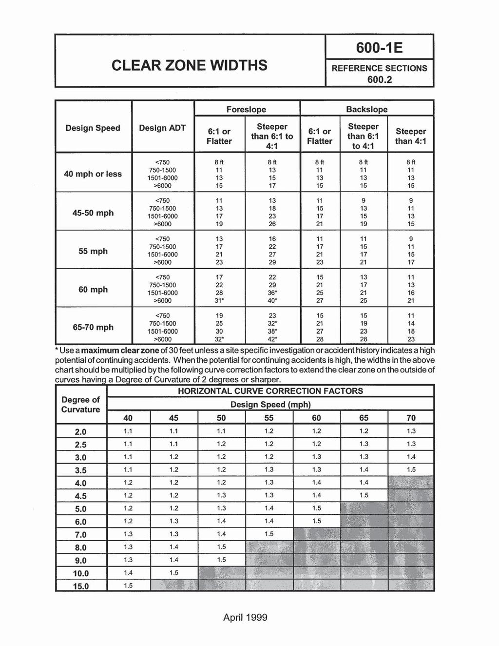
36
49-2A Clear-Zone Width for New Construction or Reconstruction B Clear-Zone Adjustment Factor, K cz, for Horizontal Curve...
 49-2A Clear-Zone Width for New Construction or Reconstruction...6 49-2B Clear-Zone Adjustment Factor, K cz, for Horizontal Curve...6 49-2C Clear-Zone Transition for Curve Adjustment, Radius 3000 ft...6
ROADSIDE SAFETY BARRIER ELEMENTS Module 3
 2 ROADSIDE SAFETY BARRIER ELEMENTS Module 3 3 Roadside Design Options 4 Expected Crash Reduction of Relocation of Fixed Objects Source: NCHRP Report 500, Vol 6, Exhibit V-26 Purpose of Safety Barriers
Section 8 -Guide Rail and Median Barriers
 Section 8-8.1 Introduction These guidelines are based on the Roadside Design Guide, AASHTO, 2011. The information in this section is intended to serve as guidelines that will assist the designer in determining
Table 8-2 Guidance for Landscape Plantings
 Sick and diseased trees that are beyond reasonable repair, along with dead trees, trees that cause sight distance problems and trees with a significant crash history shall be removed regardless of public
NOTES ON THE SPECIFICATION FOR ROAD SAFETY BARRIER SYSTEMS
 1. INTRODUCTION A road safety barrier is considered to be a hazard and should only be used when the consequences of hitting it are less than the hazard/object which it is shielding. The use of a road safety
GUIDERAILS INTRODUCTION DESIGN PURPOSE CHAPTER 12
 401 CHAPTER 12 GUIDERAILS INTRODUCTION The general intent of the highway engineer is to design a roadway in which the geometry creates a safe driving environment that does not require guiderail or median
CHAPTER 4 GRADE SEPARATIONS AND INTERCHANGES
 CHAPTER 4 GRADE SEPARATIONS AND INTERCHANGES 4.0 INTRODUCTION The ability to accommodate high volumes of intersecting traffic safely and efficiently through the arrangement of one or more interconnecting
Section 1 - Introduction Introduction Policy on Use of AASHTO Standards Reference Publications... 2
 Table of Contents Section 1 - Introduction... 1 1.1 Introduction... 1 1.2 Policy on Use of AASHTO Standards... 2 1.3 Reference Publications... 2 Section 2 - General Design Criteria... 1 2.1 General...
GEOMETRIC DESIGN CRITERIA for Non-freeway Resurfacing, Restoration, and Rehabilitation Projects
 GEOMETRIC DESIGN CRITERIA for Non-freeway Resurfacing, Restoration, and Rehabilitation Projects SEPTEMBER 1989 Arkansas State Highway and Transportation Department GEOMETRIC DESIGN CRITERIA for Non-freeway
500 Interchange Design
 500 Interchange Design Table of Contents 501 Interchange Design... 5-1 July 2015 501.1 General... 5-1 501.2 Interchange Type... 5-1 501.2.1 General... 5-1 502 Interchange Design Considerations... 5-2 502.1
Chapter URBAN & RURAL FREEWAY DESIGN
 Chapter 5 URBAN & RURAL FREEWAY DESIGN 5.1 INTRODUCTION This chapter provides standards and guidance for urban and rural freeways on new construction/reconstruction projects. The chapter also provides
500 Interchange Design
 500 Interchange Design Table of Contents 501 Interchange Design... 1 501.1 General... 1 501.2 Interchange Type... 1 501.2.1 General... 1 502 Interchange Design Considerations... 2 502.1 Determination of
CHAPTER 3 SCOPE SUMMARY
 CHAPTER 3 SCOPE SUMMARY GENERAL The SDDOT is an active member of AASHTO to share common national design standards for the state highway system. The AASHTO Task Force on Geometric Design has completed the
TRAFFIC DIRECTION FOR RAIL LAP AS SHOWN (SEE NOTE 7) "SPLICE BOLT" WITH NUT MIDWEST GUARDRAIL SYSTEM (STANDARD AND REDUCED POST SPACING)
 SPLICE BOLT WITH NUT MIDWEST GUARDRAIL SYSTEM (STANDARD AND REDUCED POST SPACING)") TRAFFIC DIRECTION FOR RAIL LAP AS SHOWN GR-MGS1, 1A (SEE NOTE 7) NOTES: 1. 2. 3. 4. 5. 6. 236 6'-3" 6'-3" 3'-1 " 3'-1 " 3'-1 " 3'-1 " GR-MGS1 (6'-3" POST SPACING) SPLICE DETAIL W-BEAM RAIL SPLICE MID-SPAN
TRAFFIC DIRECTION FOR RAIL LAP AS SHOWN GR-MGS1, 1A (SEE NOTE 7) NOTES: 1. 2. 3. 4. 5. 6. 236 6'-3" 6'-3" 3'-1 " 3'-1 " 3'-1 " 3'-1 " GR-MGS1 (6'-3" POST SPACING) SPLICE DETAIL W-BEAM RAIL SPLICE MID-SPAN
LOCATION AND DESIGN DIVISION
 VIRGINIA DEPARTMENT OF TRANSPORTATION LOCATION AND DESIGN DIVISION INSTRUCTIONAL AND INFORMATIONAL MEMORANDUM GENERAL SUBJECT: ROADWAY SAFETY FEATURES SPECIFIC SUBJECT: NCHRP 350 TEST REQUIREMENTS LOCATION
Chapter 1. General Design Information. Section 1.02 Structure Selection and Geometry. Introduction
 Chapter 1 Bridge Design Manual General Design Information Section 1.02 Selection and Geometry Introduction Selection or Rehabilitation Report This section of the design manual provides guidance on the
LOCATION AND DESIGN DIVISION
 VIRGINIA DEPARTMENT OF TRANSPORTATION LOCATION AND DESIGN DIVISION INSTRUCTIONAL AND INFORMATIONAL MEMORANDUM GENERAL SUBJECT: ROADWAY SAFETY FEATURES SPECIFIC SUBJECT: NCHRP 350 TEST REQUIREMENTS LOCATION
5.0 Plan Development. 5.1 Introduction. 5.2 Design References
 5.0 Plan Development 5.1 Introduction The plan development section of this manual is intended to assist the LPA and the designer through the preliminary engineering phase of project development. Information
Alberta Transportation Roadside Design Guide February 2012 APPENDIX E GUIDELINES FOR THE SELECTION AND DESIGN OF HIGH TENSION CABLE BARRIER SYSTEMS
 Roadside Design Guide February 2012 GUIDELINES FOR THE SELECTION AND DESIGN OF HIGH TENSION CABLE BARRIER SYSTEMS COVER PAGE February 2012 Roadside Design Guide THIS PAGE INTENTIONALLY LEFT BLANK COVER
Section 13. Guidelines for the Design of Ground Mounted Sign Supports
 Section 13 BDC11MR-04 13.1 Introduction Highway signs fall into two main categories, which are subdivided as follows: 1. Overhead Signs a. Sign Bridge Structures (GO) b. Sign Cantilever Structures (GO)
B STEEL BEAM GUIDE RAIL - OPSS 721
 B721-2 - - OPSS 721 721-2.1 GENERAL Steel Beam Guide Rail (SBGR) is a semi-rigid barrier system which restrains and redirects vehicles by a combination of beam bending (W-shaped steel section), tension,
B STEEL BEAM GUIDE RAIL - OPSS 552
 B552-2 - - OPSS 552 552-2.1 GENERAL Steel Beam Guide Rail (SBGR) is a semi-rigid barrier system which restrains and redirects vehicles by a combination of beam bending (W-shaped steel section), tension,
B STEEL BEAM GUIDE RAIL - OPSS 721
 B721-2 - - OPSS 721 721-2.1 GENERAL Steel Beam Guide Rail (SBGR) is a semi-rigid barrier system which restrains and redirects vehicles by a combination of beam bending (W-shaped steel section), tension,
MICHIGAN DESIGN MANUAL ROAD DESIGN CHAPTER
 7.01 ROADSIDE SAFETY BARRIER 7.01.01 References 7.01.02 Application of Section 7.01 MICHIGAN DESIGN MANUAL CHAPTER 7 INDEX APPURTENANCES 7.01.03 History of Guardrail and Barrier in Michigan 7.01.04 Section
CHAPTER 18 TEMPORARY ROADS AND BRIDGES
 Change #1 - Revised 12/12 CHAPTER 18 TEMPORARY ROADS AND BRIDGES 18.0 INTRODUCTION These guidelines are to be used to design temporary roads and bridges where traffic will be maintained at the construction
LOCATION AND DESIGN DIVISION
 VIRGINIA DEPARTMENT OF TRANSPORTATION LOCATION AND DESIGN DIVISION INSTRUCTIONAL AND INFORMATIONAL MEMORANDUM GENERAL SUBJECT: Design Exceptions / Waivers SPECIFIC SUBJECT: Design Exception Request Form
APPENDIX C INLETS. The application and types of storm drainage inlets are presented in detail in this Appendix.
 Storm Drainage 13-C-1 APPENDIX C INLETS 1.0 Introduction The application and types of storm drainage inlets are presented in detail in this Appendix. 2.0 Inlet Locations Inlets are required at locations
H5 Roadside and Median Barrier Systems
 Alberta Infrastructure and Transportation Roadside Design Guide November 2007 H5 Roadside and Median Barrier Systems H5.1 Introduction Barrier systems can be classified into two categories, based on their
B723 ENERGY ATTENUATORS - OPSS 723
 B723 - OPSS 723 723.1 GENERAL Various proprietary permanent and temporary energy attenuators are used to reduce the hazard associated with the ends of permanent and temporary concrete barriers. Tables
Alberta Transportation Roadside Design Guide November 2016 APPENDIX E GUIDELINES FOR THE SELECTION AND DESIGN OF HIGH TENSION CABLE BARRIER SYSTEMS
 Alberta Transportation Roadside Design Guide November 2016 APPENDIX E GUIDELINES FOR THE SELECTION AND DESIGN OF HIGH TENSION CABLE BARRIER SYSTEMS APPENDIX E COVER PAGE November 2016 Alberta Transportation
B STEEL BEAM GUIDE RAIL - OPSS.PROV 721
 B721-2 - - OPSS.PROV 721 721-2.1 GENERAL Steel beam guide rail (SBGR) is a semi-rigid barrier system which restrains and redirects vehicles by a combination of beam bending (W-shaped steel section), tension,
Page 1D-1 Revised language to link from Project Management Manual to Project Management Online Guide.
 IMPERIAL ROAD DESIGN MANUAL REVISIONS July 2008 CHAPTER 1D Page 1D-1 Revised language to link from Project Management Manual to Project Management Online Guide. CHAPTER 2A Page 2A-3 Revised language to
B STEEL BEAM GUIDE RAIL - OPSS 721
 B721-2 - - OPSS 721 721-2.1 GENERAL Design guidance and a description of Steel Beam Guide Rail systems, including various types and treatments, are provided in the Roadside Design Manual (RDM). 721-2.2
Table of Contents TOC. General Information. Street Classifications. Geometric Design Criteria
 Design Manual Chapter 5 - Roadway Design Table of Contents TOC Table of Contents Chapter 5 - Roadway Design 5A General Information 5A-1---------------------------------General Information A. Concept.....
CUYAHOGA COUNTY DEPARTMENT OF PUBLIC WORKS CUYAHOGA COUNTY ENGINEER TOWNSHIP SUBDIVISION STREET DESIGN STANDARDS AND IMPROVEMENT PLAN REQUIREMENTS
 CUYAHOGA COUNTY DEPARTMENT OF PUBLIC WORKS CUYAHOGA COUNTY ENGINEER TOWNSHIP SUBDIVISION STREET DESIGN STANDARDS AND IMPROVEMENT PLAN REQUIREMENTS November 25, 2013 Table of Contents Cuyahoga County Engineer's
DESIGN BULLETIN #75/2012 (Rewritten October 2016)
") DESIGN BULLETIN #75/2012 (Rewritten October 2016) Alberta Roadside Design Guide High Tension Cable Barrier System Median and Roadside Installation October 27, 2016 Rewrite of Design Bulletin #75/2012 April
DESIGN BULLETIN #75/2012 (Rewritten October 2016) Alberta Roadside Design Guide High Tension Cable Barrier System Median and Roadside Installation October 27, 2016 Rewrite of Design Bulletin #75/2012 April
AS THE EFFECT ON BRIDGE BARRIERS
 ABSTRACT AS5100.2 2017 THE EFFECT ON BRIDGE BARRIERS David Coe, Senior Principal, Pitt & Sherry The revision to AS5100 in 2017 resulted in significant changes to the design loading and impact heights for
Barriers, Parapets, and Railings
 Barriers, Parapets, and Railings Arielle Ehrlich State Bridge Design Engineer May 17, 2017 Bridge Office mndot.gov/bridge MnDOT Vocabulary Is it a barrier, a parapet or a railing? BARRIER. It is concrete
CHAPTER 12 INSTALLATION OF UTILITIES AND OTHER SYSTEMS TABLE OF CONTENTS
 CHAPTER 12 INSTALLATION OF UTILITIES AND OTHER SYSTEMS TABLE OF CONTENTS Section Title Page 12.1 General... 12-1 12.2 Design Standards... 12-1 12.2.1 General Requirements...12-1 12.2.2 Minimum Depth...12-1
H5 Roadside and Median Barrier Systems
 Alberta Infrastructure and Transportation November 2007 H5 Roadside and Median Barrier Systems H5.1 Introduction Barrier systems can be classified into two categories, based on their location and design:
Roadside Design Guide. Update from the Technical Committee on Roadside Safety Chris Poole, Iowa DOT
 Roadside Design Guide Update from the Technical Committee on Roadside Safety Chris Poole, Iowa DOT TCRS Strategic Plan Vision - Lead roadside policy development, support safety innovations, and be an information
EXISTING ROADWAY CONDITION ASSESSMENT REPORT (ERCAR) SAMPLE OUTLINE
 SAMPLE OUTLINE") EXISTING ROADWAY CONDITION ASSESSMENT REPORT (ERCAR) SAMPLE OUTLINE The Existing Roadway Condition Assessment Report (ERCAR) should include the evaluation of all elements against new construction criteria.
EXISTING ROADWAY CONDITION ASSESSMENT REPORT (ERCAR) SAMPLE OUTLINE The Existing Roadway Condition Assessment Report (ERCAR) should include the evaluation of all elements against new construction criteria.
T-39 Thriebeam. Product Manual. NCHRP 350 Test Level 3 & 4 Compliant Barrier. Release 01/11
 T-39 Thriebeam NCHRP 350 Test Level 3 & 4 Compliant Barrier Product Manual T-39 is licensed to Ingal Civil Products by Trinity Industries Inc. of the U.S.A. www.ingalcivil.com.au T-39 Thriebeam NCHRP 350
Technical Memorandum: Road Safety Hardware Series. technical memorandum
 technical memorandum road safety hardware series Frequently Asked Questions - Barriers & Terminals TM-2000 October 2012 Purpose To provide a list of frequently asked questions with answers in regard to
DESIGN GUIDE. Advancing Safety Through Innovation. TCC-DG01 07/18/02 Page 1
 DESIGN GUIDE Advancing Safety Through Innovation Patents Pending Copyright 2002 BSI TCC-DG01 07/18/02 Page 1 TAU-II Crash Cushion DESIGN Table of Contents Preface 22 Introduction 2 Important Information..
SECTION 6. ROAD CONSTRUCTION STANDARDS
 SECTION 6. ROAD CONSTRUCTION STANDARDS Construction of new roads or reconstruction of existing roads proposed for dedication to the County shall conform to the standards set forth in this section. Roads
B723 ENERGY ATTENUATORS - OPSS 723
 B723 - OPSS 723 723.1 GENERAL Various proprietary permanent and temporary energy attenuators are used to reduce the hazard associated with the ends of permanent and temporary concrete barriers. Tables
100 Design Controls and Exceptions
 100 Design Controls and Exceptions Table of Contents 100 Introduction... 1 101 Functional Classification... 1 101.1 General... 1 101.2 Urban & Rural... 1 101.3 Classification Used In ODOT Design Criteria...
Section 9 Guidelines for the Selection and Design of Crash Cushions
 BDC12MR-03 Section 9 Guidelines for the Selection and Design of Crash Cushions 9.1 Introduction Fixed objects within the clear zone distance should be removed, relocated or modified so as to be breakaway.
R-126-I PLACEMENT OF TEMPORARY CONCRETE BARRIER AND TEMPORARY STEEL BARRIER DETA IL 2 MICHIGAN DEPARTMENT OF TRANSPORTATION ** LATERAL OFFSET
 50' ON TANGENT (TYPICAL FOR DETAILS, 2, 3, & 4) 50' 50' 25' 25' PLASTIC DRUM LINE (SEE STANDARD PLAN R-3-SERIES) ** LATERAL OFFSET TRANSITION FROM TANGENT TO :6 FLARE RATE IN 40' MINIMUM. SLOPED END SECTION
Subject: ACTION: National Cooperative Highway Research Program (NCHRP) Report 350 Hardware Compliance Dates
 Report 350 Hardware Compliance Dates") Memorandum - FHWA Safety Program Page 1 of 2 Memorandum US Department of Transportation Federal Highway Administration Subject: ACTION: National Cooperative Highway Research Program (NCHRP) Report 350
Memorandum - FHWA Safety Program Page 1 of 2 Memorandum US Department of Transportation Federal Highway Administration Subject: ACTION: National Cooperative Highway Research Program (NCHRP) Report 350
DESIGN BULLETIN #75/2012 (Revised April 2012)
") DESIGN BULLETIN #75/2012 (Revised April 2012) Alberta Roadside Design Guide High Tension Cable Barrier System Median and Roadside Installation April 5, 2012 Amendment to Design Bulletin #75/2012 - Section
DESIGN BULLETIN #75/2012 (Revised April 2012) Alberta Roadside Design Guide High Tension Cable Barrier System Median and Roadside Installation April 5, 2012 Amendment to Design Bulletin #75/2012 - Section
T a b l e o f C o n t e n t s
 C i t y o f G l a d s t o n e P u b l i c W o r k s D e s i g n S t a n d a r d s T a b l e o f C o n t e n t s SECTION THREE SANITARY SEWER REQUIREMENTS... 1 3.0000 SANITARY SEWERS... 1 3.0010 General
Portable Changeable Message signs have a wide variety of
 Part 6F (devices) Minnesota MUTCD 2005 with 2007 09 Revisions Part 6F (devices) Federal MUTCD 2009 Part 6F (devices) MN MUTCD Rearranged Sections 6F.55 Portable Changeable Message Signs Portable Changeable
SUBJECT: Discussion Regarding Barriers & Barrier Transitions with Staff from the Midwest Roadside Safety Facility (Univ of Nebraska, Lincoln)
") Problem # 8 MnDOT Questions Regarding Bridge Barriers State Question and MwRSF Response: MnDOT had a conference call with MwRSF to discuss various questions regarding barriers on superelevations and cross
Problem # 8 MnDOT Questions Regarding Bridge Barriers State Question and MwRSF Response: MnDOT had a conference call with MwRSF to discuss various questions regarding barriers on superelevations and cross
Chapter 7. Street Drainage. 7.0 Introduction. 7.1 Function of Streets in the Drainage System. 7.2 Street Classification
 7. Introduction This chapter summarizes methods to evaluate runoff conveyance in various street cross sections and curb types in the Town of Castle Rock and identifies acceptable upper limits of street
APPENDIX A GUIDELINES FOR THE USE OF BARRIER/CHANNELIZING DEVICES IN WORK ZONES INTRODUCTION
 August 2011 Page A-1 APPENDIX A GUIDELINES FOR THE USE OF BARRIER/CHANNELIZING DEVICES IN WORK ZONES INTRODUCTION A. The following safety guidelines have been developed to provide a methodical framework
Corrugated Guardrail and Box Beam Barriers
 HIGHWAY SAFETY CORPORATION PRODUCT SHOWCASE Highway Safety Corporation has been serving the highway construction industry for over 30 years. We are a major manufacturer and supplier of highway guardrail
HIGHWAY ENGINEERING II
 HIGHWAY ENGINEERING II TRICKS AND PITFALLS - part two (For all highway engineers and designers) By: T. E. McLaughlin, PE Note: The materials used for this course include this document and several websites
CITY UTILITIES DESIGN STANDARDS MANUAL
 CITY UTILITIES DESIGN STANDARDS MANUAL Book 2 (SW) SW7 September 2017 SW7.01 Purpose The purpose of this Chapter is to establish a basis for inlet design utilizing City of Fort Wayne standard inlets and
APPENDIX A GUIDELINES FOR THE USE OF BARRIER/CHANNELIZING DEVICES IN WORK ZONES INTRODUCTION
 May 20, 2011 Draft A-1 APPENDIX A GUIDELINES FOR THE USE OF BARRIER/CHANNELIZING DEVICES IN WORK ZONES INTRODUCTION A. The following safety guidelines have been developed to provide a methodical framework
MUTCD Part 6F: Temporary Traffic Control Zone Devices
 MUTCD Part 6F: Temporary Traffic Control Zone Devices 6F.01 Types of Devices FHWA policy requires that all roadside appurtenances such as traffic barriers, barrier terminals and crash cushions, bridge
DIVISION 6. ACCESSORY USES OR STRUCTURES
 DIVISION 6. ACCESSORY USES OR STRUCTURES Sec. 58-591. Generally. (a) Principal use or structure required to be present. An accessory use or structure in any zoning district shall not be established prior
CITY OF ANN ARBOR, MICHIGAN Public Services Area/Project Management Unit 301 E. Huron Street P.O. Box 8647, Ann Arbor, Michigan 48107
 CITY OF ANN ARBOR, MICHIGAN Public Services Area/Project Management Unit 301 E. Huron Street P.O. Box 8647, Ann Arbor, Michigan 48107 Web: www.a2gov.org Printed on recycled paper May 17, 2016 Subject:
Chapter 8. Inlets. 8.0 Introduction. 8.1 General
 . Introduction This chapter provides criteria and design guides for evaluating and designing storm sewer inlets in the City of Centennial. The review of all planning submittals will be based on the criteria
CONSTRUCTION SURVEY. Construction survey includes personnel, equipment, and supplies required for, but not limited to, the following:
 CONSTRUCTION SURVEY PART 1 - GENERAL 1.01 SECTION INCLUDES Construction survey includes personnel, equipment, and supplies required for, but not limited to, the following: A. Construction Survey: 1. Project
New Jersey Turnpike Authority
 New Jersey Turnpike Authority DOCUMENT UPDATE REQUEST Forward to Assistant Chief Engineer, Design Initiator Russell Saputo, PE Submittal Date 6/21/16 Firm Stantec Consulting Services Inc. Telephone 201-587-9040
STORM DRAINAGE DESIGN MANUAL
 Appendix I STORM DRAINAGE DESIGN MANUAL by: SUNGATE DESIGN GROUP, P.A. GEN ERAL DESIGN STAN DARDS AN D POLICIES 1. STREET AND LOCAL DRAINAGE Discharge estimates for specified design storms shall be calculated
PIER PROTECTION (VEHICLE COLLISION) September 13, 2018
 September 13, 2018") PIER PROTECTION (VEHICLE COLLISION) September 13, 2018 Table of contents 1 Introduction 4-7 2 Investigation 8-19 3 Redirect vs. Structural Resistance 20-21 4 Redirect 22-33 5 Structural Resistance 34-39
PIER PROTECTION (VEHICLE COLLISION) September 13, 2018 Table of contents 1 Introduction 4-7 2 Investigation 8-19 3 Redirect vs. Structural Resistance 20-21 4 Redirect 22-33 5 Structural Resistance 34-39
CHAPTER 7 INDEX APPURTENANCES
 7.01 ROADSIDE SAFETY BARRIERS 7.01.01 References 7.01.02 Application of Section 7.01 CHAPTER 7 INDEX APPURTENANCES 7.01.03 History of Guardrail and Barrier in Michigan 7.01.04 Identification of Guardrail
GENERAL NOTES ROADWAY CONSTRUCTION RD0001-1A ISSUED:2017 REVISED: --
 ROADWAY CONSTRUCTION NOTES 1. ALL RIGHT-OF-WAY OTHER THAN ROADWAY AREAS SHALL BE SODDED. ALL SLOPE STEEPER THAN 6:1 SHALL REQUIRE SODDING. THE CITY RESERVES THE RIGHT TO REQUIRE SODDING IN SPECIAL AREAS
THE COMMONWEALTH OF MASSACHUSETTS NON-NHS BRIDGE R&R POLICY
 THE COMMONWEALTH OF MASSACHUSETTS Number: P-92-010 Date: 10-08-92 - ) HIGHWAY DEPARTMENT FROM: NON-NHS BRIDGE R&R POLICY The purpose of this Engineering Directive is to formally notify Department Personnel
Work Zone Positive Protection Toolbox
 Work Zone Positive Protection Toolbox This booklet serves as a toolbox to describe various types of positive protection devices currently in use and provides guidance on where and how each is typically
Concrete Barrier Temporary Precast
 Sheet a Sheet b Sheet c Sheet d SDD 14B7 Concrete Barrier Temporary Precast Version 12, June 11, 2010 Contact Person References Erik Emerson (608) 266-2842 Standard Spec 614 FDM 11-45-2 FDM 11-45-1 AASHTO
Review of Plans and Specs from a Constructability Perspective
 Review of Plans and Specs from a Constructability Perspective The Executive Regional Manager and the Project Manager, with approval of the Director of Project Management, may request the Constructability
Larimer County Land Use Code Section 5.8: Rural Land Use Process
 Larimer County Land Use Code Section 5.8: Rural Land Use Process 5.8.6 PRINCIPLES D. Development Standards 3. Engineering Standards and Guidelines for Roads and Drainage The following Standards and Guidelines
CHAPTER 12 BRIDGE DECK DRAINAGE SYSTEMS
 OFFICE OF STRUCTURES MANUAL FOR HYDROLOGIC AND HYDRAULIC DESIGN CHAPTER 12 BRIDGE DECK DRAINAGE SYSTEMS APRIL 2011 APRIL 2011 Page 1 Chapter Table of Contents 12.1 Policy... 12-3 12.1.1 Table 1... 12-3
AED Design Requirements: Site Layout Guidance
 US Army Corps of Engineers Afghanistan Engineer District AED Design Requirements: Various Locations, Afghanistan MARCH 2009 TABLE OF CONTENTS AED DESIGN REQUIREMENTS FOR SITE LAYOUT GUIDANCE VARIOUS LOCATIONS,
100 Introduction Functional Classification Traffic Data Terrain & Locale Design & Legal Speed...
 Table of Contents 100 Introduction... 1 101 Functional Classification... 1 101.1 General...1 101.2 Urban & Rural...1 101.3 Classification Used in ODOT Design Criteria...1 102 Traffic Data... 2 102.1 General...2
Universal TAU-II Redirective, Non-Gating, Crash Cushion
 TB 010925 Rev. 2 Page 1 of 10 Product Specification Universal TAU-II Redirective, Non-Gating, Crash Cushion I. General The Universal TAU-II system is a Redirective, Non-Gating Crash Cushion in accordance
CUYAHOGA COUNTY ENGINEER
 CUYAHOGA COUNTY ENGINEER DRAINAGE MANUAL Supplement to O.D.O.T. LOCATION and DESIGN MANUAL, Volume 2, Drainage Design, Section 1000 and 1100 May 28, 2010 Revisions to the July 29, 2009 edition are noted
EXISTING ROADWAY CONDITION ASSESSMENT REPORT (ERCAR) SAMPLE OUTLINE
 SAMPLE OUTLINE") EXISTING ROADWAY CONDITION ASSESSMENT REPORT (ERCAR) SAMPLE OUTLINE The Existing Roadway Condition Assessment Report (ERCAR) should include the evaluation of all elements against new construction criteria.
EXISTING ROADWAY CONDITION ASSESSMENT REPORT (ERCAR) SAMPLE OUTLINE The Existing Roadway Condition Assessment Report (ERCAR) should include the evaluation of all elements against new construction criteria.
TRANSMITTAL LETTER. Design Manual, Part 2 Highway Design March 2015 Edition, Change No. 2 (CT #H , Step 1 External)
") OS-299 (7-08) TRANSMITTAL LETTER PUBLICATION: Publication 13M March 2015 Edition Change No. 2 DATE: February 8, 2017 SUBJECT: Design Manual, Part 2 Highway Design March 2015 Edition, Change No. 2 (CT #H-15-007,
OS-299 (7-08) TRANSMITTAL LETTER PUBLICATION: Publication 13M March 2015 Edition Change No. 2 DATE: February 8, 2017 SUBJECT: Design Manual, Part 2 Highway Design March 2015 Edition, Change No. 2 (CT #H-15-007,
Recommended Technical Standards for Existing Roads UNH Technology Transfer Center
 Recommended Technical Standards for Existing Roads UNH Technology Transfer Center Purposes and Acknowledgements These model standards provide New Hampshire cities and towns with a set of recommendations
GUARDRAIL WARRANTS FOR LOW VOLUME ROADS
 74 GUARDRAIL WARRANTS FOR LOW VOLUME ROADS Louis B. Stephens, P.E. INTRODUCTION Low volume roads present many challenges to highway engineers and public administrators. Although, by definition, these facilities
TURNPIKE PLANS PREPARATION AND PRACTICES HANDBOOK (TPPPH) VOLUME 1
 VOLUME 1") TURNPIKE PLANS PREPARATION AND PRACTICES HANDBOOK (TPPPH) VOLUME 1 FLORIDA S TURNPIKE ENTERPRISE PRODUCTION DESIGN DEPARTMENT OCOEE, FL June 2016 January 3, 2017 Addendum #2 The following are changes,
TURNPIKE PLANS PREPARATION AND PRACTICES HANDBOOK (TPPPH) VOLUME 1 FLORIDA S TURNPIKE ENTERPRISE PRODUCTION DESIGN DEPARTMENT OCOEE, FL June 2016 January 3, 2017 Addendum #2 The following are changes,
Section 3-01 General Concepts, Design Standards and Design Exceptions TABLE OF CONTENTS
 Section 3-01 General Concepts, Design Standards and Design Exceptions TABLE OF CONTENTS GENERAL CONCEPTS...2 General...2 Design Vehicle...2 Driver Expectancy...2 Design Speed...2 Sight Distances...3 Exhibit
Bridge Barrier Development Presentation to the MFLNRO April John Deenihan Ph.D., EIT Julien Henley M.A.Sc., P.Eng
 Bridge Barrier Development Presentation to the MFLNRO April 2014 John Deenihan Ph.D., EIT Julien Henley M.A.Sc., P.Eng Contents Introduction Contents Introduction Background Information / Synopsis Contents
Chapter GRADE SEPARATIONS & INTERCHANGES
 Chapter 9 GRADE SEPARATIONS & INTERCHANGES 2012 ODOT Highway Design Manual Grade Separations And Interchanges 9.1 GENERAL INFORMATION There are three types of roadway intersections: intersections at-grade,
Technical Presentation: Specification of / for Vehicle Restraint Systems PERMANENT BARRIERS
 Technical Presentation: Specification of / for Vehicle Restraint Systems PERMANENT BARRIERS SARF Engineering for Safety seminar 29 th July 2015 Edwin Kruger (compiled with help from others) Bridge Network
Sidewalk Regulations. Table of Contents
 Sidewalk Regulations Table of Contents Section 1. Purpose and Intent... 2 Section 2. Pedestrian Sidewalk, Driveway Apron and Curb and Guttering Requirements... 2 Section 3. Sidewalk Provision Criteria...
US 14 EIS (New Ulm to N. Mankato) Interchange and Intersection Type Comparison
 Interchange and Intersection Type Comparison") T E C H N I C A L M E M O R A N D U M US 14 EIS (New Ulm to N. Mankato) Interchange and Intersection Type Comparison PREPARED FOR: Mn/DOT District 7 PREPARED BY: CH2M HILL DATE: March 27, 2007 This technical
T E C H N I C A L M E M O R A N D U M US 14 EIS (New Ulm to N. Mankato) Interchange and Intersection Type Comparison PREPARED FOR: Mn/DOT District 7 PREPARED BY: CH2M HILL DATE: March 27, 2007 This technical
Installation Manual. Orion. TL-3 Steel Barrier. VHD (v2)
") Installation Manual Orion TL-3 Steel Barrier VHD (v2) 300914 Table of Contents Orion Introduction.......... 3 Limitations & Warnings. 4 Before Installation..... 3 System Design & Design Considerations
Installation Manual Orion TL-3 Steel Barrier VHD (v2) 300914 Table of Contents Orion Introduction.......... 3 Limitations & Warnings. 4 Before Installation..... 3 System Design & Design Considerations
Section 1 OBC FADS /13 Access to Parking Areas
 Section 1 OBC 3.8.2.2 4.3.12/13 Access to Parking Areas A barrier-free path of travel is provided from: a) the entrance to the exterior parking area b) at least one parking level where a passenger elevator
ATTACHMENT 50-1: PERFORMANCE AND MEASUREMENT TABLE
 1) PAVEMENT 1.1 Ride quality All roadways have a smooth surface course (including bridge deck approaches, covers, gratings, frames and boxes). 24 hours 28 days 6 months a. Measurement of International
DIVISION I TRAFFIC IMPACT STUDY GUIDELINES ENGINEERING STANDARDS
 CITY OF ALBANY DEPARTMENT OF PUBLIC WORKS DIVISION I TRAFFIC IMPACT STUDY GUIDELINES ENGINEERING STANDARDS Prepared By PUBLIC WORKS DEPARTMENT ALBANY, OREGON 97321 Telephone: (541) 917-7676 TABLE OF CONTENTS
Nevada Department of Transportation. Road Design Guide Edition
 Nevada Department of Transportation Road Design Guide 2010 Edition Nevada Department of Transportation 1263 South Stewart Street Carson City, Nevada 89712 State of Nevada Jim Gibbons, Governor Department
SECTION 9 TRAFFIC CONTROL DURING CONSTRUCTION
 SECTION 9 TRAFFIC CONTROL DURING CONSTRUCTION Table of Contents Page No 9.1 INTRODUCTION... 1 9.2 GENERAL... 1 9.3 MAINTENANCE AND PROTECTION OF TRAFFIC PLANS... 2 9.4 TRAFFIC IMPACT REPORT... 3 9.5 DEVELOPMENT
b. Include an evaluation of maintenance of traffic for ramps, local roads and cross streets.
 630-5 Maintenance of Traffic Alternative Analysis As noted in Section 630-1, Section 1400 of the L&D Manual indicates that a Maintenance of Traffic Alternative Analysis will be performed. This analysis
CHAPTER 6 VERTICAL ALIGNMENT
 CHAPTER 6 VERTICAL ALIGNMENT INTRODUCTION...6-3 VERTICAL ALIGNMENT CONTROLS...6-3 Figure 6-1 Contrast of Poor Grade Line Design (Left) with...6-4 Preferred Grade Line Design (Right)...6-4 Figure 6-2 Example