ODOT Design & Construction Requirements for MSE Walls
|
|
|
- Nathan Rogers
- 6 years ago
- Views:
Transcription

1 ODOT Design & Construction Requirements for MSE Walls Peter Narsavage, P.E. Foundation Engineering Coordinator Ohio Department of Transportation Office of Structural Engineering 2006 Ohio Transportation Engineering Conference
2 A brief history ODOT has used MSE walls since the 1980 s. In 2004, responsibility for MSE wall construction was assigned to State Construction Geotechnical Engineer. Through 2004 and 2005, problems with MSE wall construction were investigated by OCA and OSE. Slide 2
3 A brief history OSE started preliminary development of a long-term MSE wall inspection program. ODOT begins to develop a new supplemental specification for MSE walls. Roundtable with contractors and suppliers scheduled for December, 20, Slide 3
4 A brief history December 7, 2005, District 6 shut down a three-lane collector-distributor road along I-270 in northeast Columbus because of an MSE wall problem. Drainage appears to be the cause. December 20, 2005, ODOT began a preliminary inspection program of all MSE walls built by ODOT. Inspections are completed within a month. Slide 4
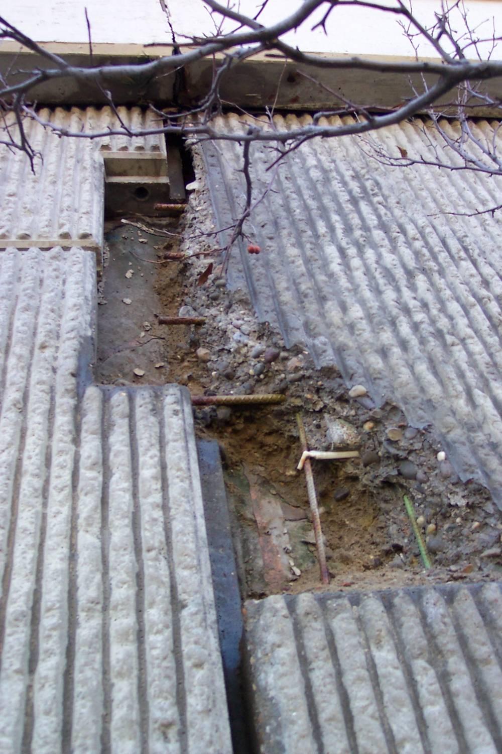
5 Problems Sand leaking from joints Settlement of panels Uncontrolled drainage Deteriorating panels Slide 5

6 Sand leaking from slip joint Slide 6

7 Sand pile under vertical joint Slide 7

8 Settlement of panels Slide 8


9 Erosion along MSE wall Slide 9


10 Void beneath slab Joint separation Slide 10

11 Final resting place of MSE wall fill Slide 11


12 Another bridge with erosion along MSE wall

13 Water probably flowed through horizontal joint Slide 13

14 Deteriorating panel Slide 14
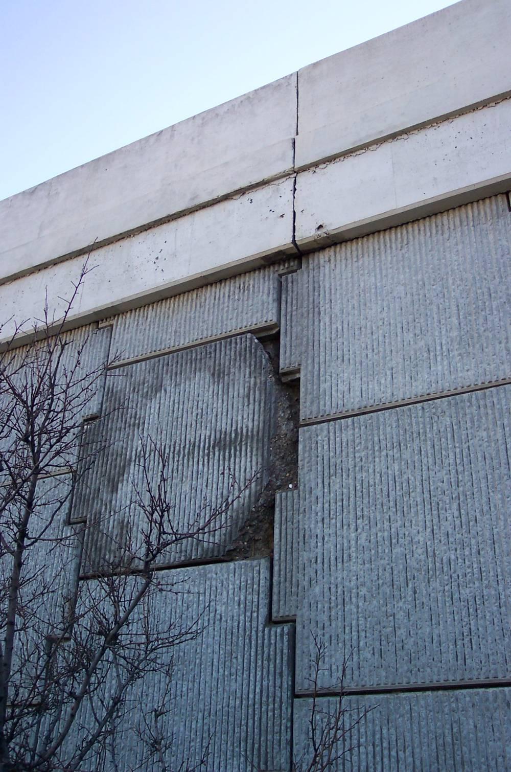
15 More deteriorating panels Slide 15
16 Preliminary inspection program Districts inspected each MSE wall. Completed inspections by Jan 20, Walls 30 percent have sand leaking from joints 32 percent have vegetation in joints 19 percent have cracked panels 11 percent have bowed or bulging walls 13 percent have some erosion 9 percent have problems with drainage system Slide 16

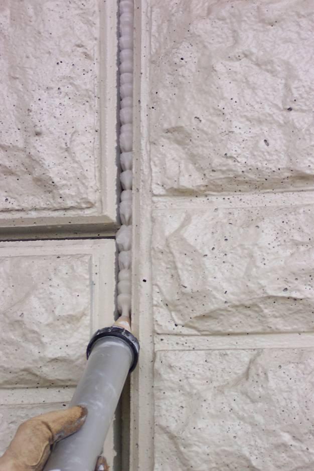

17 Sealing joints Slide 17
18 MSE wall inspection program OSE will use the information from the preliminary inspections to develop an inspection program. The program will be similar to the bridge inspection program, in that it will include: An inventory An inspection cycle An inspection manual Training and inspector qualification Slide 18
19 Design changes for MSE walls Implemented in July 2006 revisions to BDM Preference for straight MSE wall alignments Abutments supported on spread footings only under certain conditions Consider drainage around MSE walls Avoid utilities through or underneath MSE walls Slide 19
20 Preference of wall geometry at bridges 1. Straight walls 2a. Walls turned back up to 45 degrees (change of wall alignment = 135 to 179 ) 2b. Walls turned back with large radius 3. Walls turned back at 46 to 90 degrees Do not use acute corners! Slide 20

21 Straight MSE wall Slide 21

22 MSE wall turned back 45 degrees Slide 22

23 MSE wall turned back with curve Slide 23

24 MSE wall turned back 90 degrees Slide 24

25 Avoid acute corners! Slide 25

26 Avoid acute corners and minimize obstructions Don t do this. Slide 26

27 Do you think this backfill is well compacted? Slide 27
28 Bridge abutments at MSE walls If MSE wall is on bedrock, use spread footings to support bridge abutment. If MSE wall is on soil, consider possible settlement of the MSE wall Use piles if the bridge is a continuous multi-span structure or if the bridge is constructed part width in phases. If the bridge is single-span and not constructed part width, either spread footings or piles may be used to support the bridge abutment. Slide 28

29 Bridge abutments at MSE walls For piling minimum of 3-6 from the back face of the facing panels to centerline of the front row pile Should avoid this situation Slide 29
30 Bridge abutments at MSE walls For spread footing minimum of 3 from the back face of the facing panels to the front face of the footing and minimum of 5 from back face to centerline of bearings Slide 30
31 Drainage around MSE walls Control of roadway drainage is critical around MSE walls. The major problems with MSE walls have been related to the loss of drainage control. Provide barrier with a catch basin to collect the drainage. Locate catch basin 25 past the limit of the MSE wall soil reinforcement, where possible. Continue barrier 10 past catch basin. Use a minimum 30 approach slab for structures with MSE walls at the abutments. Slide 31

32 Utilities and MSE walls Avoid utilities through or underneath MSE walls. When it can t be avoided, encase the utility in a protective conduit that extends 10 beyond the limits of the select granular backfill. Pipe culverts through MSE walls should be avoided. Water and sewer lines within 10 of an MSE wall shall also be encased. X Slide 32
33 Other new MSE wall requirements Obstructions, such as piles, utilities, catch basins, etc. need to be shown on the plan, elevation, and typical sections for the MSE wall drawings. 45 degree slope of Select Granular Backfill 1 undercut with geotextile fabric and Item 203, Granular Material, Type C Bottom 3 of SGB meets gradation requirements for Item 304 Slide 33
34 Other new MSE wall requirements Select Granular Backfill 45 º Slope Retained soil 3 SGB, Item 304 Geotextile Fabric 1 Item 203, Granular Material Type C Slide 34
35 Undercuts No separate undercut and backfill pay item If undercut beyond the standard 1 is required Show undercut as additional wall excavation. Backfill with Item 203, Granular Material, Type C or D. Geotextile fabric for foundation preparation remains 1 below the bottom of the leveling pad. Slide 35
36 Undercuts Select Granular Backfill 1 Granular Material included with Foundation Preparation. Geotextile Fabric 3 SGB, Item 304 Item 203 Granular Material, Type C Additional Granular Material requires Item 203 pay item. Slide 36
37 Supplemental Specification 840 Approved July 2006 One specification that covers all accredited MSE wall systems for permanent MSE walls Added definitions Added material requirements Adjusted tolerances on facing panels and wall construction Greatly expanded construction section Created separate pay items for wall components Slide 37
38 SS 840 Definitions Defines and standardizes terminology MSE Wall System Soil Reinforcement Facing Panels Connection Device MSE Wall System Supplier Accredited MSE Wall System Precaster Slide 38
39 SS 840 Material requirements For the joint cover, require A woven, monofilament geotextile 90% UV stability after 500 hours Minimum width of 24 inches For Select Granular Backfill, require direct shear testing on material passing No. 10 sieve. φ 34º For foundation preparation, require a woven monofilament geotextile at the base of the undercut Slide 39

40 SS 840 Facing panels Precaster must be certified in accordance with Supplement 1073 Slide 40

41 SS 840 Facing panels Maximum panel size is 5 x 5 feet Gives sizes of chips or spalls, and width of cracks that are cause for panel rejection Slide 41
42 SS 840 Construction Increased from 2 to 8 pages. Preconstruction meeting is required. Foundation Preparation Compaction testing of foundation required. Department reviews foundation to verify bearing capacity. Usually performed by geotechnical consultant under consultant services. After acceptance, geotextile and 1 of granular material placed and compacted. Slide 42

43 SS 840 Construction Leveling pad is 6 x 24 Leveling pad must be within 1/8 of elevation and cannot vary more than 1/8 in 10. Facing panels cannot extend more than 6 beyond the end of the leveling pad at steps. Slide 43
44 SS 840 Construction Extensive wall erection details, such as Limit on shim size to start first row of panels Panels can t extend past the leveling pad transversely. Joints must be between ½ to 1 wide. Joint cover fabric must not be exposed. Excavation in front of the wall must be backfilled as soon as possible. Vertical and horizontal tolerances checked repeatedly. Slide 44

45 Flashlight test to see if joint cover fabric is exposed Slide 45

46 SS 840 Construction SGB placed and compacted in a manner that places the soil reinforcement in tension. Each 8 lift of SGB placed by starting 3 from facing panels and moving away from panels The lift compacted in same manner. Slide 46

47 SS 840 Construction SGB within 3 of facing panel is then placed and compacted. The compaction of each lift is tested. The compaction of every fifth lift is checked by ODOT. Slide 47
48 SS 840 Construction Concrete Sealing Exterior surfaces sealed with epoxyurethane sealer according to CMS 512. Do not damage joint cover fabric when preparing surface. On-site assistance from supplier is required. Designer Note recommends 5 days for projects with less than 4 walls. Slide 48
49 SS 840 New pay items Mechanically Stabilized Earth Wall Wall Excavation Foundation Preparation Select Granular Backfill Porous Backfill with Filter Fabric Drainage Pipe Concrete Coping On-Site Assistance SGB Inspection and Compaction Testing SF CY SY CY CY FT FT Days Lump Sum Slide 49
50 Additional MSE wall pay items 203 Items Embankment Granular Material, Types B, C, and D Included with wall quantities Item 503, Cofferdams, Cribs, and Sheeting Generally only for walls not at bridges, since the bridge plans will usually already include this item. Slide 50
51 Implementation of SS 840 ODOT is implementing SS 840 on all projects not already awarded, either by revising plans or preparing addenda. If retrofitting plans to fit SS 840, some changes are not required 45 degree slope for SGB is not required, since this will affect the limits for wall quantities. Do not need to move piling or footing, since this will extend bridge. Slide 51
MSE Walls Problems and Solutions
 MSE Walls Problems and Solutions Peter Narsavage, P.E. Foundation Engineering Coordinator Ohio Department of Transportation Office of Structural Engineering ODOT Geotechnical Workshop April 11, 2006 Problems
STATE OF OHIO DEPARTMENT OF TRANSPORTATION SUPPLEMENTAL SPECIFICATION 867 TEMPORARY WIRE FACED MECHANICALLY STABILIZED EARTH WALL.
 STATE OF OHIO DEPARTMENT OF TRANSPORTATION SUPPLEMENTAL SPECIFICATION 867 TEMPORARY WIRE FACED MECHANICALLY STABILIZED EARTH WALL April 15, 2016 867.01 Description 867.02 Definitions 867.03 Materials 867.04
STATE OF OHIO DEPARTMENT OF TRANSPORTATION SUPPLEMENTAL SPECIFICATION 840 MECHANICALLY STABILIZED EARTH WALL. January 19, 2007
 STATE OF OHIO DEPARTMENT OF TRANSPORTATION SUPPLEMENTAL SPECIFICATION 840 MECHANICALLY STABILIZED EARTH WALL January 19, 2007 840.01 Description 840.02 Definitions 840.03 Materials 840.04 Design and Submittal
MagnumStone Specifications Gravity
 MagnumStone Specifications Gravity SPECIFICATION FOR MAGNUMSTONE GRAVITY MECHANICALLY STABILIZED EARTH SYSTEM PART 1: GENERAL.01Description The work consists of supplying and installing all aspects of
STATE OF OHIO DEPARTMENT OF TRANSPORTATION SUPPLEMENTAL SPECIFICATION 840 MECHANICALLY STABILIZED EARTH WALL. July 18, 2014
 STATE OF OHIO DEPARTMENT OF TRANSPORTATION SUPPLEMENTAL SPECIFICATION 840 MECHANICALLY STABILIZED EARTH WALL July 18, 2014 840.01 Description 840.02 Definitions 840.03 Materials 840.04 Design and Submittal
UPRR INDUSTRIAL LEAD BRIDGE T-WALL RETAINING WALL SYSTEM 5.0 x 7.5 UNITS DESIGN UNIT 018 WORK PACKAGE 04
 UPRR INDUSTRIAL LEAD BRIDGE T-WALL RETAINING WALL SYSTEM 5.0 x 7.5 UNITS DESIGN UNIT 018 WORK PACKAGE 04 1. Description This work shall consist of the design, manufacture and construction of a T-WALL structure
SPECIFICATION FOR MAGNUMSTONE GEOGRID REINFORCED Mechanically Stabilized Earth (MSE) SYSTEM
 SYSTEM") MagnumStone Specifications Geogrid Reinforced SPECIFICATION FOR MAGNUMSTONE GEOGRID REINFORCED Mechanically Stabilized Earth (MSE) SYSTEM PART 1: GENERAL 1.01 Description The work consists of supplying
MagnumStone Specifications Geogrid Reinforced SPECIFICATION FOR MAGNUMSTONE GEOGRID REINFORCED Mechanically Stabilized Earth (MSE) SYSTEM PART 1: GENERAL 1.01 Description The work consists of supplying
SPECIFICATION FOR CORNERSTONE GEOGRID REINFORCED SEGMENTAL RETAINING WALL SYSTEM
 CornerStone Specifications Geogrid Reinforced SPECIFICATION FOR CORNERSTONE GEOGRID REINFORCED SEGMENTAL RETAINING WALL SYSTEM PART 1: GENERAL 1.01 Description The work consists of supplying and installing
ENGINEERING DIRECTIVE
 Number: E-95-001 Date: 2/2/95 ENGINEERING DIRECTIVE Ross B. Dindio (Signature on Original) CHIEF ENGINEER The purpose of this engineering directive is to formally notify ALL Department engineering personnel
SECTION SEGMENTAL CONCRETE UNIT MASONRY RETAINING WALL MAXIMUM HEIGHT OF 5-0 HIGH
 DIVISION 32 EXTERIOR IMPROVEMENTS SECTION 32 32 23.13 SEGMENTAL CONCRETE UNIT MASONRY RETAINING WALL MAXIMUM HEIGHT OF 5-0 HIGH PART 1: GENERAL 1.01 Scope of Standards A. This standard provides general
Earth Retaining Structures and Systems Submittal Checklist. Part One: Materials and Material Properties
 Earth Retaining Structures and Systems Submittal Checklist Part One: Materials and Material Properties Provide a sample of the reinforcement material and material specifications describing the material
SPECIFICATIONS FOR PRECAST MODULAR BLOCK RETAINING WALL SYSTEM (revised 5/8/7)
") Page 1 of 7 STONE STRONG SYSTEMS SPECIFICATIONS FOR PRECAST MODULAR BLOCK RETAINING WALL SYSTEM (revised 5/8/7) PART 1: GENERAL 1.01 Description A. Work includes furnishing and installing precast modular
Page 1 of 7 STONE STRONG SYSTEMS SPECIFICATIONS FOR PRECAST MODULAR BLOCK RETAINING WALL SYSTEM (revised 5/8/7) PART 1: GENERAL 1.01 Description A. Work includes furnishing and installing precast modular
CHAPTER 11: WALLS.
 CHAPTER 11: WALLS MODULAR BLOCK WALL (DRY CAST) Rather than being pre-approved as systems, the components of Modular block walls (dry cast) are pre-approved separately. The approved MBW components are
Hydraulic Updates. History of 603/604
 Ohio Department of Transportation John R. Kasich, Governor Jerry Wray, Director Hydraulic Updates SS 802 Constructing and Inspecting Pipe Culverts, Sewers, Drains and Drainage Structures AND SS 902 Conduit
Chapter 3 - Excavation
 Chapter 3 - Excavation South Dakota Department of Transportation Structures Construction Manual Excavation - Chapter 3 The What and Where of Excavation What is Excavation The removal of Earth material
SECTION CONCRETE SEGMENTAL RETAINING WALL SYSTEM
 Anchor Vertica SECTION 02832 CONCRETE SEGMENTAL RETAINING WALL SYSTEM PART 1 - GENERAL 1.01 SECTION INCLUDES A. Retaining wall system constructed of concrete segmental retaining wall units. B. Geosynthetic
T-WALL.
 The T-WALL Retaining Wall System is a gravity structure constructed of individual precast T-WALL units. Each T-WALL unit consists of a front face panel and a stem, which extends back into and engages the
207 TEMPORARY SEDIMENT AND EROSION CONTROLS
 2013 Construction and Material Specifications Hydraulics and Environmental Summary Ron Trivisonno, Office of Construction Administration 207 TEMPORARY SEDIMENT AND EROSION CONTROLS This item has been removed
ANSWERS TO QUESTIONS RECEIVED THROUGH 1:00 PM ON MAY 24, 2018:
 ADDENDUM NO. 3 PROJECT NO. 43805 (PART A & B) PAGE 2 ANSWERS TO QUESTIONS RECEIVED THROUGH :00 PM ON MAY 24, 208: Q#32 Addendum # answered Question #7 indicating that an average depth of 3 feet for the
MSE WALLS CASE STUDIES. by John G. Delphia, P.E. TxDOT Bridge Division Geotechnical Branch
 MSE WALLS CASE STUDIES by John G. Delphia, P.E. TxDOT Bridge Division Geotechnical Branch COMMON RETAINING WALL TYPES CONCRETE BLOCK MSE TEMPORARY EARTH SPREAD FOOTING Gabions Drilled Shaft Soil Nail Tiedback
Description. This work shall consist of furnishing materials and placement of modular block wall constructed in accordance with
 MODULAR CONCRETE BLOCK RETAINING WALL WITH GROUND REINFORCING The Standard Specifications are revised as follows: 732-R-310r 1of 11 Rev. 12-03-03 SECTION 105, AFTER LINE 48, INSERT AS FOLLOWS: When constructing
Best Practices for Design and Construction of MSE Walls
 Best Practices for Design and Construction Robert A. Gladstone, P.E. Executive Director Association for Mechanically Stabilized Earth Geotechnical Consultant Workshop Ohio Department of Transportation
SECTION SPECIFICATION FOR STONEBRIDGE RETAINING WALL SYSTEM
 SECTION 32 32 23 SPECIFICATION FOR STONEBRIDGE RETAINING WALL SYSTEM PART 1: GENERAL 1.01 Scope Work includes furnishing all materials, labor, equipment, and supervision to install a Stonebridge segmental
Chapter 1 INTRODUCTION
 Chapter 1 Final SCDOT GEOTECHNICAL DESIGN MANUAL August 2008 Table of Contents Section Page 1.1 Introduction... 1 1.2 Preconstruction Division... 1 1.2.1 Regional Production Groups... 2 1.2.2 Preconstruction
SPECIFICATIONS FOR PRECAST MODULAR BLOCK RETAINING WALL SYSTEM (revised 9/17/18)
") Page 1 of 8 STONE STRONG SYSTEMS SPECIFICATIONS FOR PRECAST MODULAR BLOCK RETAINING WALL SYSTEM (revised ) PART 1: GENERAL 1.01 Description A. Work includes furnishing and installing precast modular blocks
Page 1 of 8 STONE STRONG SYSTEMS SPECIFICATIONS FOR PRECAST MODULAR BLOCK RETAINING WALL SYSTEM (revised ) PART 1: GENERAL 1.01 Description A. Work includes furnishing and installing precast modular blocks
SECTION Segmental Concrete Unit Masonry Retaining Wall Height Over 5-0 High
 PART 1: GENERAL 1.0 0 Scope of Standards A. This standard provides general guidance concerning the specific preferences of the Texas State University for a Segmental Retaining Wall up to 5-0 high. B. Texas
Special Provision No. 599S22 March 2018 REQUIREMENTS FOR RETAINED SOIL SYSTEMS (RSS)
") RETAINED SOIL SYSTEM, TRUE ABUTMENT - Item No. RETAINED SOIL SYSTEM, FALSE ABUTMENT - Item No. RETAINED SOIL SYSTEM, WALL/SLOPE, HIGH PERFORMANCE - Item No. RETAINED SOIL SYSTEM, WALL/SLOPE, MEDIUM PERFORMANCE
RETAINED SOIL SYSTEM, TRUE ABUTMENT - Item No. RETAINED SOIL SYSTEM, FALSE ABUTMENT - Item No. RETAINED SOIL SYSTEM, WALL/SLOPE, HIGH PERFORMANCE - Item No. RETAINED SOIL SYSTEM, WALL/SLOPE, MEDIUM PERFORMANCE
PROPOSED SEGMENTAL RETAINING WALLS ARGONAUT RETAIL VILLAGE - PHASE I PENSACOLA, FLORIDA
 CERTIFICATE AUTHORIZATION: 2 24 ANCHOR WALL ENGINEERING, LLC MATERIAL NOTES. Concrete Retaining Wall Units: "Anchor Diamond Pro Retaining Wall Units" as manufactured by Block USA under license from Anchor
Excavate drilled shafts in accordance with Item 416, Drilled Shaft Foundations.
 Item Excavation and Backfill for Structures 1. DESCRIPTION 2. MATERIALS Excavate for placement and construction of structures and backfill structures. Cut and restore pavement. Use materials that meet
Michigan State University Construction Standards SEGMENTAL CONCRETE RETAINING WALLS PAGE SECTION SEGMENTAL CONCRETE RETAINING WALLS
 PAGE 323223-1 SECTION 323223 PART 1 - GENERAL 1.1 RELATED DOCUMENTS A. Drawings and general provisions of the Contract, including General and Supplementary Conditions and Division 01 Specification sections,
2.1 Backfill - General
 2.1 Backfill - General Excavations are made for the purpose of constructing bridge substructure elements, and consequently requiring competent backfill material. The backfill material must be adequately
SECTION SEGMENTAL RETAINING WALL
 Note: This guide specification should not be included entirely as-is. Specification writers must edit areas in red which may or may not be relevant to a specific project or where mutually exclusive choices
2. City of Seattle Supplement to the Specification for Road, Bridge and Municipal Construction, most current addition.
 Design Guide Basis of Design This section applies to the design and installation of earthwork and backfill. Design Criteria No stockpiling of excavation materials is allowed unless the Geotechnical Engineer
Designer Supplement: AS-2-15 Approach Slab Installation January 16, 2015
 1 Overview: The purpose of Standard Bridge Drawing, AS-2-15, is to address details of approach slabs not previously addressed in the AS-1-81 Standard Bridge Drawing. Specifically, the drawing was initiated
T-WALL Retaining Wall System
 CONSTRUCTION MANUAL T-WALL Retaining Wall System The T-WALL Solution... THE NEEL COMPANY 8328 Traford Lane Springfield, VA 22152 Phone 703-913-7858 Fax 703-913-7859 T-WALL Retaining Wall System CONSTRUCTION
Reinforced Soil Slopes (RSS)
") Supplemental Technical Specification for Reinforced Soil Slopes (RSS) SCDOT Designation: SC-M-206-1 (4/16) 1.0 DESCRIPTION 1.1 Construct a reinforced soil slope in accordance with these specifications,
Supplemental Technical Specification for Reinforced Soil Slopes (RSS) SCDOT Designation: SC-M-206-1 (4/16) 1.0 DESCRIPTION 1.1 Construct a reinforced soil slope in accordance with these specifications,
204 - EXCAVATION AND BACKFILL FOR STRUCTURES SECTION 204 EXCAVATION AND BACKFILL FOR STRUCTURES. Granular Backfill (Wingwalls) (Set Price)
 (Set Price)") SECTION 204 EXCAVATION AND BACKFILL FOR STRUCTURES 204.1 DESCRIPTION Excavate for the structures as shown in the Contract Documents. Unless specified otherwise, backfill the completed structures to the
SECTION 204 EXCAVATION AND BACKFILL FOR STRUCTURES 204.1 DESCRIPTION Excavate for the structures as shown in the Contract Documents. Unless specified otherwise, backfill the completed structures to the
1.02 RELATED WORK: Refer to the following sections for related work: Section 4000-Concrete Materials and Methods
 SECTION 2000- EARTHWORK PART 1- GENERAL 1.01 SCOPE: This Section covers excavation, fill, and compaction of earth and rock for roadway, embankments, structural foundations, and planted areas. Topics include
CHAPTER 13 - MECHANICALLY STABILIZED EARTH WALLS AND PATENTED EARTH RETAINING SYSTEMS
 CHAPTER 13 - MECHANICALLY STABILIZED EARTH WALLS AND PATENTED EARTH RETAINING SYSTEMS DS Temple 13.1 SCOPE This section covers the inspection of mechanically stabilized earth walls and other patented earth
Uwall UNIVERSAL CONSTRUCTION MANUAL
 Uwall UNIVERSAL Retaining Wall System CONSTRUCTION MANUAL TM President s Letter CSI is a leader in its industry supplying precast infrastructure products throughout New England and beyond since 1972, developing
DESIGNING AND CONSTRUCTION OF T-WALL RETAINING WALL SYSTEM
 Istanbul Bridge Conference August 11-13, 2014 Istanbul, Turkey DESIGNING AND CONSTRUCTION OF T-WALL RETAINING WALL SYSTEM T. C. NEEL and K.BOZKURT ABSTRACT This work shall consist of the design, manufacture
MANDATORY SUPPLEMENTAL SPECIFICATIONS FOR CONTRACTOR QUALITY CONTROL Contractor Quality Control - is replaced with the following:
 MANDATORY SUPPLEMENTAL SPECIFICATIONS FOR CONTRACTOR QUALITY CONTROL EFFECTIVE DATE: OCTOBER 14, 2011 200.07 Contractor Quality Control - is replaced with the following: (a) (b) (c) Scope: These requirements
SPECIAL SPECIFICATION 4653 Polypropylene Pipe
 2004 Specifications CSJ 2158-01-013, Etc. SPECIAL SPECIFICATION 4653 Polypropylene Pipe 1. Description. Furnish and install polypropylene pipe for constructing polypropylene pipe culverts or polypropylene
SECTION CONCRETE SEGMENTAL RETAINING WALL SYSTEM
 Anchor [beveled-face and straight-face products] SECTION 32 32 23 CONCRETE SEGMENTAL RETAINING WALL SYSTEM PART 1 GENERAL 1.01 SECTION INCLUDES A. Concrete segmental retaining wall units B. Geosynthetic
SECTION TRENCHING
 SECTION 31 23 17 TRENCHING PART 1 GENERAL 1.1 SUMMARY A. Section Includes: 1. Excavating trenches for utilities and utility structures. 2. Bedding. 3. Backfilling and compacting to subgrade elevations.
Geotechnical Specification and Construction Update
 Geotechnical Specification and Construction Update Steve Slomski, P.E. Office of Construction Administration Topics 2016 C&MS Revisions Supplemental Specifications & Supplements Revisions & Additions Construction
Notes for Erection of Evergreen Maxi Wall Retaining Walls
 Notes for Erection of Evergreen Maxi Wall Retaining Walls 1. Evergreen Maxi General Notes A. Project drawings - See project drawings for complete layout of utilities, railroad tracks, existing and proposed
SECTION CONCRETE SEGMENTAL RETAINING WALL SYSTEM BIG BLOCK / WETCAST
 LondonBoulder Retaining Wall Units SECTION 32 32 23 CONCRETE SEGMENTAL RETAINING WALL SYSTEM BIG BLOCK / WETCAST PART 1 - GENERAL 1.01 SECTION INCLUDES A. Retaining wall system constructed of wet-cast
Section 401. PIPE CULVERTS
 401.02 Section 401. PIPE CULVERTS 401.01. Description. This work consists of constructing pipe culverts of the size and class required, including excavation and backfill. 401.02. Materials. Provide materials
Final Estimates Level 2
 Florida Department of TRANSPORTATION Final Estimates Level 2 Module 6: Structures 11/1/2017 FDOT Final Estimates Level 2 Release 11, Module 6 1 6-1 Module Content Concrete Structures Bridges Substructure
DECEMBER 5, 2017 AT 2:00 P.M. (EASTERN TIME) (Estimated Cost: $5,000,000) Bids
 (Estimated Cost: $5,000,000) Bids") General Info Number: PROJECT NO. 43-17-04 : BRIDGE DECK REPAIR AND BRIDGE REMOVAL OHIO TURNPIKE OVER QUARRY ROAD, M.P. 138.0 OHIO TURNPIKE OVER INACTIVE RAILROAD, M.P. 138.2 LORAIN COUNTY, OHIO Deadline:
General Info Number: PROJECT NO. 43-17-04 : BRIDGE DECK REPAIR AND BRIDGE REMOVAL OHIO TURNPIKE OVER QUARRY ROAD, M.P. 138.0 OHIO TURNPIKE OVER INACTIVE RAILROAD, M.P. 138.2 LORAIN COUNTY, OHIO Deadline:
SECTION BUILDING EARTHWORK
 Conditions of Use/ Responsibility of Data Montgomery County Public Schools Facilities Guide DIVISION 2 - SITE WORK These guideline specifications are to be used by the A/E as a base document in the development
SECTION CONCRETE SEGMENTAL RETAINING WALL SYSTEM
 SECTION 02832 CONCRETE SEGMENTAL RETAINING WALL SYSTEM PART 1.: GENERAL 1.01 WORK INCLUDED A. This section includes the following: The Specifications on furnishing the design, materials and labor required
CONSTRUCTION MANUAL 2.5 x 5 UNITS
 CONSTRUCTION MANUAL 2.5 x 5 UNITS www.neelco.com 8328-D Traford Lane, Springfield, VA 22152 703 913 7858 T-WALL Retaining Wall System CONSTRUCTION Manual Contents Part I earthwork... 1 The Structure depends
Ohio Department of Transportation Division of Production Management Office of Geotechnical Engineering. Geotechnical Bulletin
 Ohio Department of Transportation Division of Production Management Office of Geotechnical Engineering Geotechnical Bulletin GB 2 SPECIAL BENCHING AND SIDEHILL EMBANKMENT FILLS Geotechnical Bulletin GB2
SPECIAL SPECIFICATION 4425 Thermoplastic Pipe
 2004 Specifications CSJ 0264-07-028 SPECIAL SPECIFICATION 4425 Thermoplastic Pipe 1. Description. Furnish and install thermoplastic pipe for constructing thermoplastic pipe culverts or thermoplastic storm
STANDARD SPECIFICATION FOR CRIBLOCK CONCRETE CRIBWALL
 STANDARD SPECIFICATION FOR CRIBLOCK CONCRETE CRIBWALL 1. SCOPE 2. DESIGN 3. MATERIALS 4. CONSTRUCTION 5. METHOD OF MEASUREMENT AND PAYMENT SCOPE This Specification sets out requirements for the design,
LANDSCAPE RETAINING WALLS
 SUDAS Standard Specifications Division 9 - Site Work and Landscaping Section 9070 - Landscape Retaining Walls LANDSCAPE RETAINING WALLS PART - GENERAL.0 SECTION INCLUDES A. Modular Block Retaining Walls
SEGMENTAL BLOCK RETAINING WALLS. Comply with Division 1 - General Provisions and Covenants, as well as the following:
 SEGMENTAL BLOCK RETAINING WALLS PART 1 - GENERAL 1.01 SECTION INCLUDES Segmental Block Retaining Walls 1.02 DESCRIPTION OF WORK Constructing segmental block retaining walls. 1.03 SUBMITTALS Comply with
Bureau of Materials Materials Approval Procedures
 Bureau of Materials Materials Approval Procedures MAP Number: 116-15 Effective Date: April 1, 2015 Approved By: Eileen Sheehy PROCEDURE FOR APPROVAL OF MECHANICALLY STABILIZED EARTH (MSE) RETAINING WALL
SECTION MECHANICALLY STABILIZED EARTH 1.01 SUMMARY
 SECTION 028300 PART 1 GENERAL 1.01 SUMMARY A. Section includes Basis of Design Mechanically Stabilized Earth System: SierraScape Mechanically Stabilized Earth (MSE) retaining wall system having high density
Tensar MesaTM Retaining Wall System Initial Report August Reporting on Work Plan 2001-S-9 Category ll Experimental Project
 Tensar MesaTM Retaining Wall System Initial Report 2006-5 August 2006 Reporting on Work Plan 2001-S-9 Category ll Experimental Project State of Vermont Agency oftransportation Materials and Research Neale
ATTACHMENT 50-1: PERFORMANCE AND MEASUREMENT TABLE
 1) PAVEMENT 1.1 Ride quality All roadways have a smooth surface course (including bridge deck approaches, covers, gratings, frames and boxes). 24 hours 28 days 6 months a. Measurement of International
SECTION MECHANICALLY STABILIZED EARTH RETAINING WALLS
 SECTION 13100 MECHANICALLY STABILIZED EARTH RETAINING WALLS PART 1 -- GENERAL 1.01 THE REQUIREMENT A. Includes all labor, material, equipment, testing and submittals required to design and complete construction
CONCRETE SEGMENTAL RETAINING WALL SYSTEM
 CONCRETE SEGMENTAL RETAINING WALL SYSTEM PART 1: GENERAL SPECIFICATIONS 1.01 Work Included A. Work shall consist of furnishing and constructing a Rockwood Classic 8, Classic 6 and Legend unit segmental
CYPRESS Stone Geogrid Reinforced Retaining Wall Installation Specification SECTION CONCRETE SEGMENTAL RETAINING WALL PART 1 GENERAL
 CYPRESS Stone Geogrid Reinforced Retaining Wall Installation Specification SECTION 02832- CONCRETE SEGMENTAL RETAINING WALL PART 1 GENERAL 1.01 Description A) The work covered by this section includes
SECTION SPECIFICATION FOR MECHANICALLY STABILIZED EARTH TWO STAGE WALL SYSTEM
 SECTION 02830 SPECIFICATION FOR MECHANICALLY STABILIZED EARTH TWO STAGE WALL SYSTEM ## THIS SECTION IS WRITTEN IN CSI 3-PART FORMAT AND IN CSI PAGE FORMAT. NOTES TO THE SPECIFIER, SUCH AS THIS, ARE INDICATED
Maine Turnpike Authority
 Company Name Total Bid Amount CPM Constructors - Freeport, ME $13,984,117.36 Reed & Reed, Inc. - Woolwich, ME $14,883,139.00 Page 1 of 11 CPM Constructors Freeport, ME 201.11 Clearing AC 2.00 10000.00
SECTION LIMESTONE SEGMENTAL RETAINING WALLS
 (Specifier Notes: The purpose of this guide specification is to assist the specifier in correctly specifying segmental retaining walls and their installation. The specifier needs to edit this guide specification
Installation Manual. ArchCast Bridge. 3-Sided Precast Concrete Bridge Structure
 ArchCast Bridge 3-Sided Precast Concrete Bridge Structure Installation Manual Salem Location: 749 West Commercial Ave. Salem, IL 62881 (618) 548-1190 countymaterials.com Email: info@countymaterials.com
T-WALL & STONE STRONG
 shawprecastsolutions.com & STONE STRONG Retaining Walls PRODUCT GUIDE & TECHNICAL REFERENCE MANUAL Providing the right solutions. The Retaining Wall System is a gravity structure constructed of individual
Redi Rock Specification and Installation Manual
 Redi Rock Specification and Installation Manual 1.0 General Scope This Specification covers the Design, Materials and Installation of Redi Rock modular block Retaining and Freestanding Wall systems as
Grade separated interchange at the intersection of U.S. Hwy 17 Bypass and Farrow Parkway
 Grade separated interchange at the intersection of U.S. Hwy 17 Bypass and Farrow Parkway Jeff Sizemore, P.E. Geotechnical Design Support Engineer SCDOT Ed Tavera, P.E. Principal Geotechnical Engineer Geoengineers
OHIO DEPARTMENT OF TRANSPORTATION CENTRAL OFFICE, 1980 W. BROAD ST., COLUMBUS, OHIO
 OHIO DEPARTMENT OF TRANSPORTATION CENTRAL OFFICE, 1980 W. BROAD ST., COLUMBUS, OHIO 43216-0899 July 20, 2018 To: Users of the Bridge Design Manual From: Tim Keller, Administrator, Office of Structural
Inspector s Manual for Mechanically Stabilized Earth Walls
 Nebraska Transportation Center Report SPR-P1 (09) P320 Final Report 26-1114-0023-001 Inspector s Manual for Mechanically Stabilized Earth Walls Wayne Jensen, Ph.D. Associate Professor The Charles W. Durham
GEOSYTHETIC SLOPE SPEC-V0704rev.doc STANDARD SPECIAL PROVISION FOR GEOSYNTHETIC REINFORCED SLOPE CONSTRUCTION
 GEOSYTHETIC SLOPE SPEC-V0704rev.doc STANDARD SPECIAL PROVISION FOR GEOSYNTHETIC REINFORCED SLOPE CONSTRUCTION I. DESCRIPTION - This work consists of furnishing the required materials and construction of
REGIONAL CONSTRUCTION STANDARDS
 REGIONAL CONSTRUCTION STANDARDS SIXTH EDITION Publication Update 6.5 (Full Committee Approved Proposed Revision 6.5 Storm Sewer Joint Wrap - Section 302 As Publication Update 6.5) March 27, 2018 Copyright
StormPod Arch Installation Guide
 StormPod Arch Installation Guide xx Foundation Bed Preparation Use standard construction procedures for the construction of the bed for StormPod Modular Arch Systems. As with any construction project,
Strengthened Soil Wall Construction Manual
 Strengthened Soil Wall Construction Manual This information has been prepared by Shaw Technologies, Inc. as an aid in constructing their Strengthened Soil Wall system. Final determination of the suitability
Section G1. Design of Cast-In-Place Box Conduits
 G1-1 Economy of Design 1. Height to Width Ratio Section G1 Design of Cast-In-Place Box Conduits Careful economic studies should be made to determine the greatest economy of the entire storm drain. As an
CONSTRUCTION SURVEY. Construction survey includes personnel, equipment, and supplies required for, but not limited to, the following:
 CONSTRUCTION SURVEY PART 1 - GENERAL 1.01 SECTION INCLUDES Construction survey includes personnel, equipment, and supplies required for, but not limited to, the following: A. Construction Survey: 1. Project
Draft. Not Yet Approved SECTION 10.1 GENERAL SCOPE DEFINITIONS
 SECTION 10.1 GENERAL 10.1.1 SCOPE This part of the Manual covers the structural design and installation of reinforced concrete pipe for railway culverts. Pipe geometry may be circular, arch, or elliptical.
DIVISION 4100 SITEWORK
 DIVISION 4100 SITEWORK SECTION 4115 EARTHWORK PART 1 - GENERAL 1.01 SCOPE This section covers the grading and compaction of excavations, embankments, structural foundations, and planted areas. 1.02 REFERENCES
UNIFIED FACILITIES GUIDE SPECIFICATIONS
 USACE / NAVFAC / AFCEC / NASA UFGS-02 66 10 (February 2010) ----------------------------- Preparing Activity: USACE Superseding UGGS-02 66 10 (April 2006) UNIFIED FACILITIES GUIDE SPECIFICATIONS References
Table of Contents 5.1 GENERAL Overview Investigation and Engineering Information
 Table of Contents Section Page 5.1 GENERAL... 5.1-1 5.1.1 Overview... 5.1-1 5.1.2 Investigation and Engineering Information... 5.1-2 5.2 PRELIMINARY GEOTECHNCIAL REPORTS... 5.2-1 5.2.1 Preliminary Geotechnical
CUYAHOGA COUNTY, OHIO ADDENDUM NUMBER 1, APRIL 25, 2018 FOR THE CITY OF BRECKSVILLE,
 CUYAHOGA COUNTY, OHIO ADDENDUM NUMBER 1, APRIL 25, 2018 FOR THE FOR THE CUYAHOGA COUNTY DEPARTMENT OF PUBLIC WORKS RQ# 41677 BIDS DUE ON: May 1, 2018, at 2:00 p.m. ADDENDUM NUMBER 1, April 25, 2018, Page
SPECIAL SPECIFICATION 4xxx Thermoplastic Pipe
 2004 Specifications SPECIAL SPECIFICATION 4xxx Thermoplastic Pipe 1. Description. Furnish and install thermoplastic pipe for constructing thermoplastic pipe culverts or thermoplastic storm sewer mains,
SAMPLE CONSTRUCTION AND MATERIAL SPECIFICATIONS FOR THE ULTRABLOCK GRAVITY WALL SYSTEM
 SAMPLE CONSTRUCTION AND MATERIAL SPECIFICATIONS FOR THE ULTRABLOCK GRAVITY WALL SYSTEM The following paragraphs provide general guidelines on developing construction and material specifications for specific
A.2.a Random Riprap... Table
 3601 RIPRAP MATERIAL 3601.1 SCOPE Provide stone and filter layer material for use in random or hand-placed riprap, gabion, and revet mattress construction. 3601.2 REQUIREMENTS A Stones A.1 Quality Provide
MassBloc Permeable Instant Wall System
 PIPELINE SYSTEMS 131 004 www.rocla.com.au MassBloc Permeable Instant Wall System PIPELINE SYSTEMS MassBloc Retaining Wall Permanent Retaining Structures The Rocla MassBloc retaining wall system comprises
SECTION 303 CULVERTS
 303.01 Scope - This section covers the construction of pipe culverts. 303.01.01 Definitions for the purposes of this section, the following general terms are defined as follows: a) Backfilling means the
Wall Modular Block Mechanically Stabilized Earth, Item S.
 Wall Modular Block Mechanically Stabilized Earth, Item 532.0300.S. A Description (1) This special provision describes designing, furnishing materials and erecting a permanent earth retention system in
HYDROLOGIC RESTORATION OF THE CASH CREEK BASIN IN TATE'S HELL STATE FOREST
 HYDROLOGIC RESTORATION OF THE CASH CREEK BASIN IN TATE'S HELL STATE FOREST CONSTRUCTION PLAN BID SET PREPARED FOR: LOCATION MAP CARRABELLE US ROUTE 319/98 EASTPOINT Prepared By Plan Design Enable CORPORATE
CHAPTER 2. Restricted Residential ½ Street** Design Speed 25 MPH 25 MPH 25 MPH 25 MPH 40 MPH 50 MPH 55 MPH
 CHAPTER 2 201 ROADS 201.1 General This section is to assist the designer in determining what is needed for the design of roads in public rights-of-way. For these standards, the terms used are: Restricted
Anchorplex retaining wall construction guide
 Anchorplex retaining wall construction guide Building Anchorplex Retaining Wall Systems Table of Contents and Introduction table of contents ow to Use This Guide......................... 2 About the Anchorplex
FEBRUARY 13, 2019 AT 2:00 P.M. (EASTERN) (Estimated Cost: $9,000,000.00) Bids. Kokosing Construction Company, Inc. $8,623,609.96
 (Estimated Cost: $9,000,000.00) Bids. Kokosing Construction Company, Inc. $8,623,609.96") General Info Number: PROJECT NO. 43-19-02 Description: BRIDGE DECK REPAIR AND REHABILITATION OHIO TURNPIKE OVER ABANDONED RAILROAD M.P. 34.2, OHIO TURNPIKE OVER STATE ROUTE 108 M.P. 34.5, COUNTY ROUTE
General Info Number: PROJECT NO. 43-19-02 Description: BRIDGE DECK REPAIR AND REHABILITATION OHIO TURNPIKE OVER ABANDONED RAILROAD M.P. 34.2, OHIO TURNPIKE OVER STATE ROUTE 108 M.P. 34.5, COUNTY ROUTE
CONSTRUCTION SPECIFICATION FOR CONCRETE BARRIERS
 ONTARIO PROVINCIAL STANDARD SPECIFICATION METRIC OPSS 553 FEBRUARY 1991 CONSTRUCTION SPECIFICATION FOR CONCRETE BARRIERS 553.01 SCOPE 553.02 REFERENCES 553.03 DEFINITIONS TABLE OF CONTENTS 553.04 SUBMISSION
OHIO DEPARTMENT OF TRANSPORTATION CENTRAL OFFICE, 1980 W. BROAD ST., COLUMBUS, OHIO
 OHIO DEPARTMENT OF TRANSPORTATION CENTRAL OFFICE, 1980 W. BROAD ST., COLUMBUS, OHIO 43216-0899 January 20, 2012 To: Users of the Bridge Design Manual From: Tim Keller, Administrator, Office of Structural
Monumental Blok. Pallet Overview. Compatible caps. Notes. code 3521 (a) 3522 (b) 3523 (c) texture Chiseled. Specifications per pallet.
 3522 (b) 3523 (c) texture Chiseled. Specifications per pallet.") Monumental Blok code 3521 (a) 3522 (b) 3523 (c) texture Chiseled Pallet Overview (see below) HALF Specifications per pallet Imperial Metric Cubing 13.80 ft 2 /pal. (1.28 m 2 )/pal. 1.73 ft 2 /unit (0.16
Monumental Blok code 3521 (a) 3522 (b) 3523 (c) texture Chiseled Pallet Overview (see below) HALF Specifications per pallet Imperial Metric Cubing 13.80 ft 2 /pal. (1.28 m 2 )/pal. 1.73 ft 2 /unit (0.16
Gravity Wall. A force to be reckoned with... Gravity (SRW) segmental retaining wall systems are structures
 segmental retaining wall systems are structures") A force to be reckoned with... Gravity (SRW) segmental retaining wall systems are structures lower in height that use the FrogStone unit weight combined with gravel core infill to resist earth pressures
A force to be reckoned with... Gravity (SRW) segmental retaining wall systems are structures lower in height that use the FrogStone unit weight combined with gravel core infill to resist earth pressures