Instructions for 12 and 15 IGT systems (12 pictured)
|
|
|
- Justina Cunningham
- 6 years ago
- Views:
Transcription
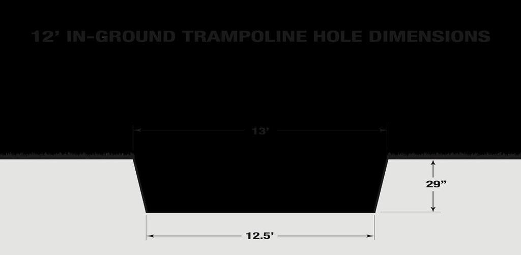
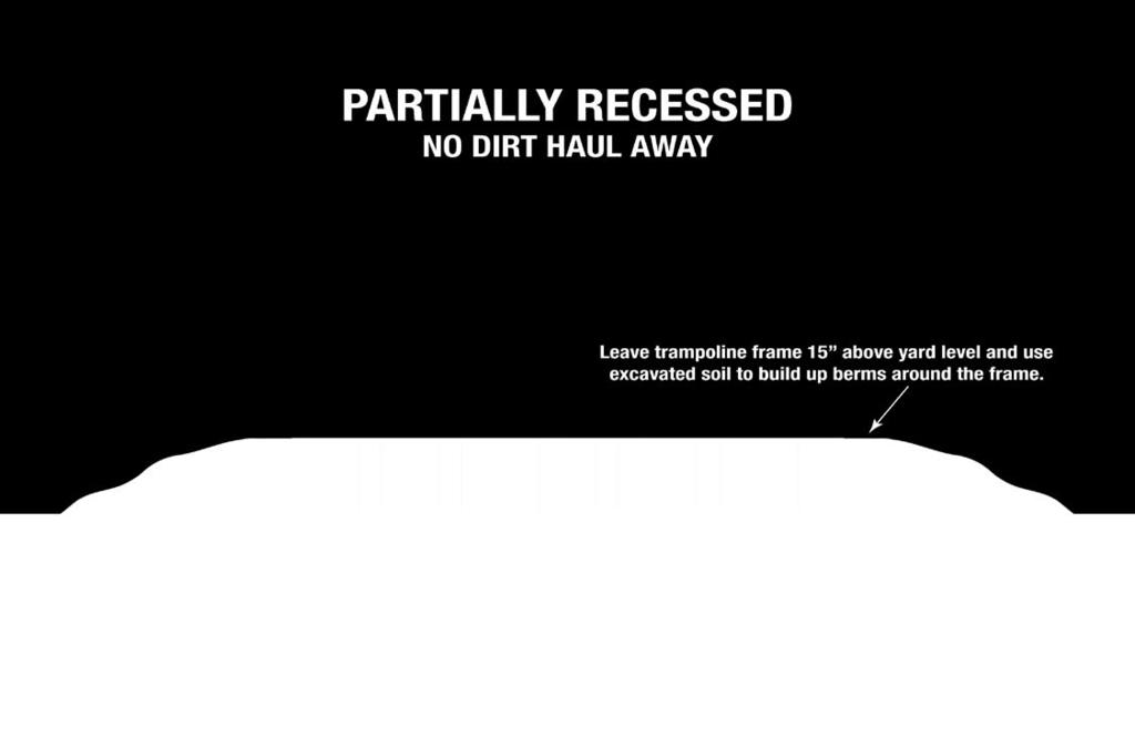
1 Instructions for 12 and 15 IGT systems (12 pictured) Step 1: IGT Site Preparation Site Location Several factors must be considered when choosing the site for your new In-Ground Trampoline (IGT) system. Since local soil and weather conditions vary greatly from region to region, it is recommended that a local landscape expert be consulted for placement of the system. A minimum of 18 feet of overhead clearance and 5 feet of clearance from the trampoline to other objects on the ground is recommended for the jumpers protection. Using impact-absorbing ground cover such as grass, sand or bark chips is recommended for 6 to 8 feet around the trampoline. Drainage Drainage is not a problem with our In-Ground Trampoline system. It is recommended to leave at least 4 inches of the trampoline above the final grade and gradually burming the soil up to the edge of the trampoline. This will keep water from flowing into the pit in the event of heavy rain. Depending on local soil conditions you may consider adding 4 to 6 inches of gravel into the bottom of the pit, creating a sump effect to prevent standing water. Extreme conditions may require additional drainage methods or the use of a sump pump. It is always a good idea to consult a local landscaper regarding local soil conditions and drainage for your area. The Pit The IGT system is designed to be installed partially or completely recessed in the ground. Either way, the pit will need to be excavated to a diameter of 13 feet for the 12 model and 16 feet for the 15 model. If the IGT system must be assembled in the pit due to size constraints of the yard, a 14 foot pit for the 12 model and 17 foot pit for the 15 model is recommended for easier access to assembly hardware. For a completely recessed system we recommend the excavation of the pit depth be inches deep. See below for Pit Dimensions. The system is a total of 33 inches tall so this allows for the trampoline to remain at least 2-4 inches above the grade as recommended in the Drainage section. For a partially recessed system, the dirt excavated from the pit can be used to build up the area around the installation. Excavating the pit to a depth of 18 inches leaves 15 inches of the system exposed. This method eliminates the need for removing excavated soil from the property.
2
3 Details on Trampoline Installation Depth The IGT system is a total of 33 inches tall. Excavation to a depth of inches will leave the frame 2-4 inches above the yard grade. This will keep water out of the IGT system. In order to have the trampoline appear to be flush in the yard, simply use excavated soil to create a burm up to the edge of the frame. See diagram below.
4
 24 30 Side Panels 24 30 Rubber Edge Protector Strips 1 1 Pad Set 1 1 Jumping")

5 Step 2: Lay Out Parts Parts list Quantity 12 Foot 15 Foot Description Top Frame Segments (10 hole) Bottom Frame Segments (4 hole) Side Panels Rubber Edge Protector Strips 1 1 Pad Set 1 1 Jumping Surface Springs Bolts Nuts Washers 1 1 Tool Kit Lay Out Parts for Easy Installation Lay out parts as shown to simplify assembly of the frame. Use one of the shipping boxes to separate all the hardware.

6 Step 3: Frame Assembly Tips - Use the assembled lower frame ring as a template to help locate and mark for pit excavation. - Assembly should occur next to the excavated pit. If there is no room for assembly close to the pit, it can be assembled in the pit however it is recommended to excavate the diameter of the pit to 14 feet for the 12 model and 17 for the 15 model for easier access to the hardware. - Be sure the spring holes on the top frame segments are facing up. - Leave all bolts loose to allow movement of the components during assembly for easier bolt hole alignment. - Unless you are on a perfectly level surface for assembly, some holes may be difficult to line up. Use a long screwdriver to help locate and align holes Step A: Assemble lower frame ring section. Assemble lower ring using the 12/15 lower frame segments.


7 Step B: Join 3 wall panels with one top frame segment. Lay 3 panels on the ground overlapping each other so the holes are aligned. Attach the top holes of the panel (holes closest to the edge with the protector strip) to the upper frame segment using a bolt and washer on the panel side and a nut and washer on the frame side as shown in the photo below right. Make sure the spring holes are facing up on the top frame segment. Do not tighten the bolts at this time. Step C: Join the 3 wall panels and upper segment to the lower frame ring. To make assembly easier, use the shipping boxes to support the lower frame ring about 6 inches off the ground while attaching the wall panels. Attach the assembly from step 2 to any place on the lower frame ring using a bolt and washer on the panel side and a nut and washer on the frame side. Do not tighten bolts at this time.


8 Step D: continue adding wall panels and upper frame segments. Attach 1 wall and 1 upper frame segment at a time always starting with upper bolts first. Use the Allen wrench to help push the bolts through the holes. Step E: Complete the frame assembly. The final wall panel and upper segment installation may require lifting and/or shifting the frame. This is why the bolts should be left loose until the frame is completed. Be sure all edge protectors are properly seated prior to tightening the hardware. When all components and hardware are in place, tighten all bolts. The frame/wall panel bolt should protrude about ¼ inch past the nut when tightened. Do not over tighten and crush the wall panel.


 255 lbs (15 ) and will require 3 to")
9 The Frame is now complete Step 4: Position Frame Assembly into Pit Install The frame can now be placed into the excavated hole. The completed frame weighs 235 lbs. (12 ) 255 lbs (15 ) and will require 3 to 4 adults to position the frame into the pit.


10 Level Frame A level frame is important for safe trampoline use. Use a string level or similar device to make sure the frame is completely level before continuing. Backfill Backfill the frame assembly using the excavated soil. Try to use loose dirt free of large clumps. The final landscape can be finished at this point if desired or later. It is important to have the final surface, whether it is grass or mulch etc, at the same level as the top of the frame. For a good flush look, you may need to start the backfill up to the edge of the frame from 2-3 feet away from the trampoline gradually sloping up from the existing yard grade up to the top of the frame.


11 Step 5: Install Jumping Surface Attach Every 4 th Spring Using the provided spring tool, start at any point attaching every 4 th spring from the frame to the rings on the jump mat, skipping 3 holes on the frame and 3 rings on the mat. Although it is hard to see, the spring has a large hook and a small hook. (See photo) Make sure the small hook is attached to the jump mat first and then using the spring tool, pull the larger hook and attached to the frame. It is very important to attach springs in the correct pattern. Be sure the D ring on the jump mat is oriented properly. NO!


12 Attach middle springs Attach the springs in the middle of the first round of springs Attach all remaining springs Make sure the springs already attached are correct. There will be a frame hole and mat ring for each spring. After the pattern is confirmed correct, attach the rest of the springs to the frame and mat.

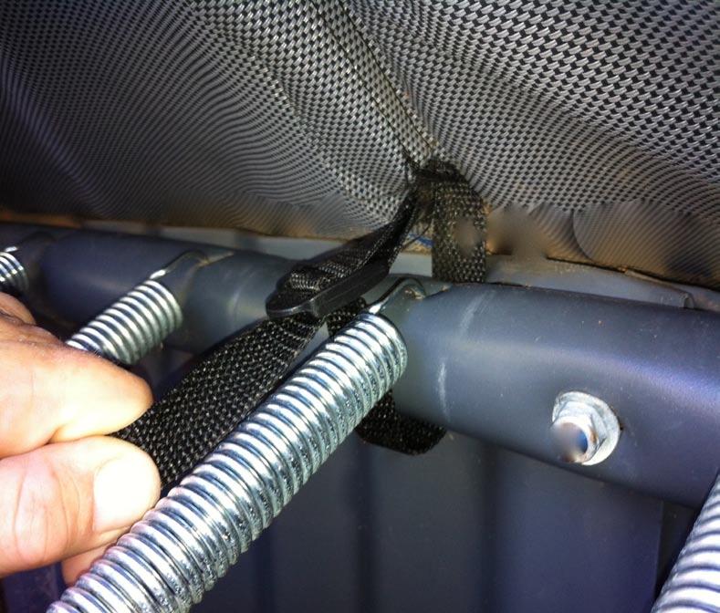
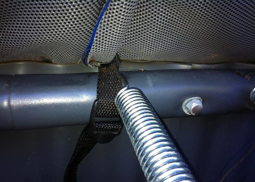
13 Step 7: Attach pad Edge protector Before installing pads, make sure the Edge Protector is properly in place Install pad Lay the pad out on the perimeter of the trampoline. At this point you must lie down on top of trampoline jump surface and lift up the edge of the pad to gain access to the tie straps located on the bottom side of the pad. Secure the pad by slipping the strap down between the frame tube and wall panel on either side of one of the frame/wall panel bolts. Pass the end of the strap though the buckle pull tightly so the pads will not slide around. The ties will line up with every other frame assembly bolt.
14

15 You are now finished with the IGT installation!
Instructions for 12 IGT system
 Instructions for 12 IGT system Step 1: IGT Site Preparation Site Location Several factors must be considered when choosing the site for your new In-Ground Trampoline (IGT) system. Since local soil and
PYZIQUE FRESTANDING & RETAINING WALL
 PYZIQUE FRESTANDING & RETAINING WALL 120 Cambridge Wall Book Pyzique Cambridge Wall Book 121 Pyzique Wall PYZIQUE WALL ONE STONE DOES IT ALL! The Trapezoid shape (4 in. high x 9in. deep x 11 in. and 7
Gravity Wall. A force to be reckoned with... Gravity (SRW) segmental retaining wall systems are structures
 segmental retaining wall systems are structures") A force to be reckoned with... Gravity (SRW) segmental retaining wall systems are structures lower in height that use the FrogStone unit weight combined with gravel core infill to resist earth pressures
A force to be reckoned with... Gravity (SRW) segmental retaining wall systems are structures lower in height that use the FrogStone unit weight combined with gravel core infill to resist earth pressures
Installation Manual. ArchCast Bridge. 3-Sided Precast Concrete Bridge Structure
 ArchCast Bridge 3-Sided Precast Concrete Bridge Structure Installation Manual Salem Location: 749 West Commercial Ave. Salem, IL 62881 (618) 548-1190 countymaterials.com Email: info@countymaterials.com
Premier Railroad Grade Crossing Installtion Guide PREMIER RAILROAD GRADE CROSSING INSTALLTION GUIDE GUIDE GROUNDED IN STRENGTH
 Premier Railroad Grade Crossing Installtion Guide PREMIER RAILROAD GRADE CROSSING INSTALLTION GUIDE GUIDE GROUNDED IN STRENGTH RELIABILITY STARTS WITH A WELL-DESIGNED PLAN. THE RIGHT PRODUCT FOR THE RIGHT
EASY RIDER (MUSTANG) EASY RIDER (PONY) EASY RIDER (ZEBRA) EASY RIDER (BRONCO)
 EASY RIDER (PONY) EASY RIDER (ZEBRA) EASY RIDER (BRONCO)") Page 1 * IMPORTANT * PLEASE RETAIN THIS INSTRUCTION SHEET IN YOUR FILES. IT CONTAINS IMPORTANT REPLACEMENT PARTS INFORMATION. ALL EQUIPMENT SHOULD BE INSTALLED IN ACCORDANCE WITH THESE INSTRUCTIONS. IT
Page 1 * IMPORTANT * PLEASE RETAIN THIS INSTRUCTION SHEET IN YOUR FILES. IT CONTAINS IMPORTANT REPLACEMENT PARTS INFORMATION. ALL EQUIPMENT SHOULD BE INSTALLED IN ACCORDANCE WITH THESE INSTRUCTIONS. IT
WARNING- THIS EQUIPMENT IS DESIGNED FOR ADULTS ONLY. ONLY HEALTHY PEOPLE AGES 13 AND UP SHOULD USE THE EQUIPMENT.
 INSTALLATION DETAILS Recommended crew (Adult): 2 Installation time: 2 hours (plus time for concrete to cure) User age: 13 and up Weight: 163 lbs MAINTENANCE: As the owner of the equipment you are responsible
FITNESS PLAYGROUND ITEM NO: 8010
 FITNESS PLAYGROUND ITEM NO: 8010 OWNER S MANUAL CAUTION: This unit is designed to be used safely by up to 4 children between the ages of 3 years to 8 years old with a maximum weight of 100 pounds (45.4
H 12 Heavy Duty Modern Tripod 8 Seat Swing Heavy Duty Hangers
 Page 1 IMPORTANT Please retain this instruction sheet in your files. It contains important replacement parts information. All equipment should be installed in accordance with these instructions. It is
VERsacourt LED Light System Installation Instructions
 VERsacourt LED Light System Installation Instructions PART LIST TEE BAR ASSEMBLY 10 12 LIGHT ASSEMBLY (hardware included) EXTENSION COLLAR BASE POLE EXTENSION POLE ANCHOR PAGE 1 REQUIRED TOOLS AND MATERIALS
IMPORTANT. Use of safety surfacing (wood mulch) in compliance with ASTM specification F1292 is required. WARNING
 in compliance with ASTM specification F1292 is required. WARNING") INSTALLATION DETAILS Recommended crew (Adult): 2-3 Installation time: 8-12 Hours not including concrete cure time User age: 5-12 Use zone: 22 Diameter Weight: 990 Actual Dimension: 120 Diameter MAINTENANCE:
INSTALLATION DETAILS Recommended crew (Adult): 2-3 Installation time: 8-12 Hours not including concrete cure time User age: 5-12 Use zone: 22 Diameter Weight: 990 Actual Dimension: 120 Diameter MAINTENANCE:
Foundation Manual. Part Number: Version: Updated: July 5, S. Meadows Pkwy. A-9, #329 Reno, NV
 Foundation Manual Part Number: 150002 Version: 1.22 Updated: July 5, 2009 748 S. Meadows Pkwy. A-9, #329 Reno, NV 89521 775-831-9463 www.mariahpower.com July 2009, Mariah Power, All Rights Reserved Dear
EASY RIDER (MUSTANG) EASY RIDER (PONY) EASY RIDER (ZEBRA) EASY RIDER (BRONCO)
 EASY RIDER (PONY) EASY RIDER (ZEBRA) EASY RIDER (BRONCO)") Page 1 * IMPORTANT * PLEASE RETAIN THIS INSTRUCTION SHEET IN YOUR FILES. IT CONTAINS IMPORTANT REPLACEMENT PARTS INFORMATION. ALL EQUIPMENT SHOULD BE INSTALLED IN ACCORDANCE WITH THESE INSTRUCTIONS. IT
Page 1 * IMPORTANT * PLEASE RETAIN THIS INSTRUCTION SHEET IN YOUR FILES. IT CONTAINS IMPORTANT REPLACEMENT PARTS INFORMATION. ALL EQUIPMENT SHOULD BE INSTALLED IN ACCORDANCE WITH THESE INSTRUCTIONS. IT
SpaVault TM Installation Guide for Bullfrog Spas (7-10 x 7-10 x 38 )
") SpaVault TM Installation Guide for Bullfrog Spas (7-10 x 7-10 x 38 ) WARNING - When unpacking SpaVault, DO NOT discard styrofoam pieces, these are not packaging materials. Step 1 Excavation Important:
SpaVault TM Installation Guide for Bullfrog Spas (7-10 x 7-10 x 38 ) WARNING - When unpacking SpaVault, DO NOT discard styrofoam pieces, these are not packaging materials. Step 1 Excavation Important:
INSTALLATION GUIDE PLEASE READ ENTIRE INSTRUCTION MANUAL BEFORE PROCEEDING!
 DURA - TRENCH INSTALLATION GUIDE This guide is intended to aide in the installation of Dura-Trench systems. There are many different applications and situations for the use of this product and the installation
RETAINING WALL SIGMA WALL 6 AND 8 SIGMA. cambridgewallsupport.com cambridgepavers.com FIND MORE DETAILS AT
 BACKYARD PATIOS & OUTDOOR LIVING ROOMS PAVINGSTONES WALL SYSTEMS SIGMA WALL 6 AND 8 SIGMA RETAINING WALL FIND MORE DETAILS AT cambridgewallsupport.com cambridgepavers.com 41 W Cambridge Sigma Wall System
MODEL # MSC-4120-BM. Spring Breeze with Me and My Toddler Metal Swing Chair OWNER S MANUAL
 MODEL # MSC-4120-BM Spring Breeze with Me and My Toddler Metal Swing Chair OWNER S MANUAL ASSEMBLY, INSTALLATION, CARE, MAINTENANCE AND USER INSTRUCTIONS FOR RESIDENTIAL USE ONLY WARNING This product is
Aegis Heavy Capacity 20K Floor Scale. MODEL: 6200 Series. Installation Manual
 Installation Manual Aegis Heavy Capacity 20K Floor Scale MODEL: 6200 Series Copyright 1997-2014 Fairbanks Scales, Inc. Revision 3 50637 All Rights Reserved 07/14 Aegis Heavy Capacity 20K Floor Scale Model:
You will probably need to perform this procedure in the loading dock area of the building. A fork lift or chain hoist may be needed.
 This chapter contains the following sections: Unpacking a Cisco R-Series Rack, page Remove the Packaging, page Accessories, page 3 Safety Guidelines, page 4 Removing the Cisco Cisco R4262 Rack from the
GENERAL ASSEMBLY CONSIDERATIONS FOR TERRAN SACON BUILDINGS AND STRUCTURES
 GENERAL ASSEMBLY CONSIDERATIONS FOR TERRAN SACON BUILDINGS AND STRUCTURES This document should not be considered specifications. Each project has site specific requirements and should develop individual
Cedar Flooring Rounds
 Cedar Flooring Rounds (Formerly Tree Cookie Flooring) #3902 Installation Instructions Please open and inspect all items upon receipt. If you have any questions or concerns, please contact us immediately.
Model # BARK /26/2012 Page 1 of 5
 Model # BARK-430 6/26/2012 Page 1 of 5 6/26/2012 Page 2 of 5 1675 Locust Street Red Bud, IL 62278 Phone: 618-282-8200 Fax: 618-282-8202 WARRANTY & TERMS WARRANTY: 5 Year Limited Warranty on Thermoplastic/Canine
HOW TO INSTALL PATIOS AND WALKWAYS STEP 2 STEP 1. For all Patios and Walkways. The base is the most important step in your patio and walkway projects.
 New Project (replacing grass/dirt) STEP 1 PREPARING YOUR PROJECT AREA Determine how much to excavate using the example below. Remove the grass to desired depth (skim rather than dig deep) and a few inches
INSTALLATION MANUAL. All Types F Series Rev G
 INSTALLATION MANUAL All Types - 1570 F Series Page 1 of 16 TABLE OF CONTENTS DESCRIPTION PAGE GENERAL INFORMATION & ADVISORIES 2 PRODUCT INFORMATION 3 GET TO KNOW YOUR CBU 4 HARDWARE AND COMPONENTS 5 CONCRETE
GUIDELINE FOR PLANTED INFILL INSTALLATIONS. Please read prior to installation, and have proper equipment and safety precautions in place.
 GUIDELINE FOR PLANTED INFILL INSTALLATIONS Please read prior to installation, and have proper equipment and safety precautions in place. For additional information please visit our website at www.soilretention.com
2004 Specifications CSJ SPECIAL SPECIFICATION DIRECT FIXATION TRACK CONSTRUCTION
 2004 Specifications CSJ 0920-38-250 SPECIAL SPECIFICATION 7660 DIRECT FIXATION TRACK CONSTRUCTION 1. Description. This section specifies the construction of direct fixation (DF) track to the lines and
Installation Manual. Foundations. Version 2
 Installation Manual Foundations Version 2 Contents Overview...1 Planning the Job... 2 Introducing DMX FlexSheet...2 Supplies Required...3 Tools Required...4 Preparing the Site...4 Where to Start?...5 Installing
ROOF MOUNT KIT OWNERS MANUAL
 ROOF MOUNT KIT OWNERS MANUAL Made in the USA by: Primus Wind Power, Inc. 938 Quail St. Lakewood, CO 80215 Phone: (303) 242-5820 www.primuswindpower.com AIR is a trademark of Primus Wind Power, Inc. ROOF
Rough-in frame and flush-mount panel installation instructions
 Welch Allyn, Inc. 3 State Street Road Skaneateles Falls, NY 33 USA Rough-in frame and flush-mount panel installation instructions 726080 DIR 8002869 Ver. A Revised 206- The Welch Allyn In-Floor Scale models
GroundTrac. Installation Manual
 APPLICATION: The GroundTrac system is designed with a minimum amount of installed footings at greatly reduced labor. The system integrates with ordinary 1-1/2 schedule #40 galvanized water pipe. This ground
DRIVABLE GRASS GUIDELINE FOR NON PLANTED DRY INFILL INSTALLATIONS
 DRIVABLE GRASS GUIDELINE FOR NON PLANTED DRY INFILL INSTALLATIONS Please read through this instruction completely before beginning your installation. Be sure the proper equipment, and safety precautions
DRIVABLE GRASS GUIDELINE FOR DRIVABLE TURF INSTALLATION
 DRIVABLE GRASS GUIDELINE FOR DRIVABLE TURF INSTALLATION Please read through this instruction completely before beginning your installation. Be sure the proper equipment, and safety precautions are in place.
Playground Review and Maintenance Process
 Playground Review and Maintenance Process Line of Business: General Liability Risk Control Strategy/Key Issues: Establish procedures for existing playground equipment review to comply with current safety
ROOF MOUNT KIT OWNERS MANUAL
 ROOF MOUNT KIT OWNERS MANUAL Made in the USA by: Southwest Windpower, Inc. 1801 W. Route 66 Flagstaff, Arizona 86001 Phone: (928) 779-9463 Fax: (928) 779-1485 E-mail: info@windenergy.com Web: www.windenergy.com
INSTRUCTION MANUAL.
 INSTRUCTION MANUAL www.waterscapesinternational.com TABLE OF CONTENTS Product Specifications Page 2 WATER GARDENS Determining Pond Volume Page 3 Determining Surface Area Page 3 Streambed Construction Page
Heartland Perma-Column 1841 E 1450 Rd. Lawrence, KS (785)
") Perma-Column Installation Instructions Unlike any other concrete post-frame foundation system, Perma-Column Precast Concrete Piers use 10,000 psi concrete and our unique Sturdi-Wall Plus wet-set bracket
Perma-Column Installation Instructions Unlike any other concrete post-frame foundation system, Perma-Column Precast Concrete Piers use 10,000 psi concrete and our unique Sturdi-Wall Plus wet-set bracket
Garden WallScape Installation Guide
 By CornerStone Wall Solutions Inc. Garden WallScape Installation Guide GRAVITY/DETAILS The perfect balance... between design and nature Garden WallScape Overview note: bolded terms are defined in our online
INSTALLING A POUR-IN-PLACE DOCK LEVELER (EH & RR)
") INSTALLING A POUR-IN-PLACE DOCK LEVELER (EH & RR) Part A: Prepare the Site & Make the Floor 1.) Prepare (concrete) dock wall and pit floor as shown in the diagrams. Pit floor should taper from back to
INSTALLING A POUR-IN-PLACE DOCK LEVELER (EH & RR) Part A: Prepare the Site & Make the Floor 1.) Prepare (concrete) dock wall and pit floor as shown in the diagrams. Pit floor should taper from back to
EXISTING CONDITIONS. Town of Bedford, NH Sand Volleyball Courts Existing Conditions Sheet 2 of 5 GENERAL NOTES
 GENERAL NOTES 1. THE CONTRACTOR SHALL VERIFY AND DETERMINE THE LOCATION, SIZE AND ELEVATION OF ALL EXISTING UTILITIES SHOWN OR NOT SHOWN ON THESE PLANS PRIOR TO THE START OF ANY CONSTRUCTION. THE CONTRACTOR
Conergy SolarFamulus II
 Conergy SolarFamulus II Installation manual www.conergy.com Table of Contents Table of Contents SolarFamulus II for universal use on flat roofs 1 Introduction 1 1.1 Short description 1 1.2 Intended use
ASHWELL FIRE PIT SIENNA QUARRY GRAY TAN AUTUMN BLEND. Plan Date: June 2016
 ASHWELL FIRE PIT QUARRY GRAY 198-620 SIENNA 198-621 TAN 198-622 AUTUMN BLEND 198-623 Plan Date: June 2016 Approximate Weight: 1,300 lbs Approximate Size: 4 2 Ext. 3 0 Intr. 1 2 H www.midwestmanufacturing.com
PV Mounting System 2703 SERIES 200 UL GROUND MOUNT SYSTEM. SnapNrack Residential PV Mounting Systems Code Compliant Installation Manual
 PV Mounting System 2703 SERIES 200 UL GROUND MOUNT SYSTEM SnapNrack Residential PV Mounting Systems Code Compliant Installation Manual Series 200 UL Introduction Series 200 UL Introduction SnapNrack Series
UNIVERSITY OF MISSOURI Electrical Manholes and Handholes 2016 Q1
 GENERAL: The scope of this document is to provide instruction for the design and installation of medium voltage concrete electric manholes and handholes. DESIGN GUIDELINES: 1. Design for Manhole 1.1. The
PATENTS ARE PENDING. Building Dimensions. Exterior Dimensions Roof Edge to Roof Edge
 Assembly Manual 8x5 PATENTS ARE PENDING Approximate Size 7980303 Storage Area Building Dimensions Exterior Dimensions Roof Edge to Roof Edge Interior Dimensions Wall to Wall Sq. Ft. Cu. Ft. Width Depth
PATENTS ARE PENDING. Building Dimensions. Exterior Dimensions Roof Edge to Roof Edge
 Assembly Manual 8x9 PATENTS ARE PENDING Approximate Size 7640303 Storage Area Building Dimensions Exterior Dimensions Roof Edge to Roof Edge Interior Dimensions Wall to Wall Sq. Ft. Cu. Ft. Width Depth
JUNGLE CONTAINED PLAY INSTALLATION INSTRUCTIONS 1
 WWW.SPORTSPLAYINC.COM 1 TOP DOWN VIEW SIDE VIEW WWW.SPORTSPLAYINC.COM 2 Bird/ PANEL 1 PANEL 2 PANEL 3 PANEL 4 PANEL 5 PANEL 6 PANEL 7 PANEL 8 WWW.SPORTSPLAYINC.COM 3 902-795 JUNGLE CONTAINED PLAY PANEL
PLEASE READ ENTIRE INSTRUCTION MANUAL BEFORE PROCEEDING!
 INSTALLATION GUIDE This guide is intended to aide in the installation of Dura-Trench systems. There are many different applications and situations for the use of this product and the installation procedures
Five Stone System. Trench Depth Compactible Rock. Foundation. 57 lbs 41 lbs 31 lbs 47 lbs. Patent Pending. Approximate Weight
 Five Stone System Patent Pending Introduction to the Multi-Use, Multi-Stone System The multi-use, multi-stone system has been developed to give a natural stone appearance to a manufactured system. The
6x5. Assembly Manual CAUTION. Sharp Edges PATENTS ARE PENDING. Building Dimensions. Approximate Size. Storage Area. Interior Dimensions
 Assembly Manual 6x5 PATENTS ARE PENDING Building Dimensions Approximate Size Storage Area Exterior Dimensions Interior Dimensions Roof Edge to Roof Edge Wall to Wall Sq. Ft. Cu. Ft. Width Depth Height
44 Installation Instructions: Olde English Radius Wall Double-Sided Freestanding Wall
 44 Olde English Radius Wall Double-Sided Freestanding Wall This project will outline a freestanding or sitting wall. Shown is an Olde English Radius freestanding, double-sided sitting wall with Cambridge
36" CRESTONE FIRE RING
 6" CRESTONE FIRE RING SIENNA: TAN: AUTUMN BLEND: RED/BLACK: RED: QUARRY GRAY: 198-652 198-65 198-656 198-654 198-655 198-651 Approximate Weight: 950 lbs Approximate Size: 4ft. in. Exterior Dimension X
PRODUCT INFORMATION Dero Hoop Rack
 PRODUCT INFORMATION Dero Hoop Rack 2946 Larimer St. Denver, CO 80205 303-295-1100 / 800-373-7693 FAX 303-295-2464 Email info@snyderequipment.com www.snyderequipment.com H O O P R A C K The Hoop Rack is
28 BELGIAN WEDGE FIRE RING
 28 BELGIAN WEDGE FIRE RING SKU: 198-920 Approximate Weight: 895 lbs Approximate Size: ft. 6 in. Ext. 2 ft. 4 in. Intr. 10-1/2 in. H www.midwestmanufacturing.com BELGIAN WEDGE BLOCKS KIT MATERIALS Color
Stretch Your Dollar Theme Designs Fire Pit
 Stretch Your Dollar Theme Designs Fire Pit Tools Garden gloves Garden hose String (5 length) Stake Hammer or rubber mallet 3 Mason Chisel Tape measure 2 level 4 level (most homeowners don t have. We don
1 of 1 04/09/ :41
 1 of 1 04/09/2008 06:41 Buried Shipping Containers http://web.archive.org/web/20031124215255/www.cont 1 of 5 04/09/2008 06:41 DO IT YOURSELF...Partial Burial Example FIND A SITE AND EXCAVATE FOR A PARTIAL
Grizzly TM Part Number Spectrum Lane ~ Missoula MT ~
 Grizzly TM Part Number 21655 7100 Spectrum Lane ~ Missoula MT 59808 800.791.8056 ~ www.spectrumproducts.com 21655 Man Rev B You have purchased a Spectrum Products Grizzly starting platform. Providing the
COUNTY BLOCK. Construction Guidelines on County Block Steps. Special Considerations When Building Steps. Natural Beauty Absolute Strength
 Construction Guidelines on County Block Limits of Liability This County Block Installation Guide provides general information about the product, including installation procedures, technical and engineering
STAGE MANUAL PLEASE GET APPROVAL FROM LOCAL AUTHORITY FOR USE IN YOUR AREA.
 PLEASE GET APPROVAL FROM LOCAL AUTHORITY FOR USE IN YOUR AREA. 1 Steps: BEFORE YOU START BUILDING You need to make sure to measure the overall footprint of the desired stage on the venue floor. If the
CHAPTER 13 - MECHANICALLY STABILIZED EARTH WALLS AND PATENTED EARTH RETAINING SYSTEMS
 CHAPTER 13 - MECHANICALLY STABILIZED EARTH WALLS AND PATENTED EARTH RETAINING SYSTEMS DS Temple 13.1 SCOPE This section covers the inspection of mechanically stabilized earth walls and other patented earth
Mounting systems for solar technology
 Mounting systems for solar technology ASSEMBLY INSTRUCTIONS CROSSRAIL TILT KIT 7 / 0 / 5 TILT FOR LOW-SLOPE AND STEEP-SLOPE ROOFS TABLE OF CONTENTS TABLE OF CONTENTS THE COMPANY SAFETY REGULATIONS MATERIALS
3.2 SuperTie 50K Installation Guide
 3.2 SuperTie 50K Installation Guide FORM ERECTION 1. This G50K Gripper has been shipped partially disassembled. It is necessary for you only to attach the base plate. The Gripper Body, Base Plate, and
INSTRUCTIONS FOR THE ASSEMBLY AND INSTALLATION OF THE VORTOX LIQUID SAMPLER
 INSTRUCTIONS FOR THE ASSEMBLY AND INSTALLATION OF THE VORTOX LIQUID SAMPLER I. SAMPLER SUSPENDED BY CABLE The Vortox Liquid Sampler is a precision instrument manufactured of stainless steel, easy to install,
CONSULTANT PROCEDURES & DESIGN GUIDELINES Electrical Manholes and Handholes UNIVERSITY OF MISSOURI
 GENERAL: The scope of this document is to provide instruction for the installation of concrete electric manholes. DESIGN GUIDELINES: 1. Materials for Manhole 1.1. Cast-in-Place or Pre-Cast concrete may
4 EXTREME FOUNDATION PANELS
 4 EXTREME FOUNDATION PANELS For House Crawl Space On Concrete Footings 1. The type of soil is a factor in determining foundation construction details such as footing design, backfill, and drainage provisions.
CONSTRUCTION MANUAL. T-WALL Retaining Wall System FOR RAILROAD PROJECTS. The T-WALL Solution...
 T-WALL Retaining Wall System CONSTRUCTION MANUAL FOR RAILROAD PROJECTS T-WALL railroad units are 5.0' high x 7.5' wide. (stem lengths will vary) The T-WALL Solution... T-WALL Retaining Wall System CONSTRUCTION
G R A V I T Y / G E O G R I D
 GRAVITY/GEOGRID MAGNUMSTONE Overview note: bolded terms are defined in our online glossary at www.cornerstonewallsolutions.com The MagnumStone retaining wall system was developed with the installer in
General Guidelines. Tools Required. Steel Folding Scooter & Wheelchair Carrier Instructions for Part # SC400-V2. Safety
 Steel Folding Scooter & Wheelchair Carrier Instructions for Part # SC400-V2 General Guidelines It is the user s responsibility to read and follow all instructions. Keep these instructions with the product
SPECIFICATION FOR CORNERSTONE GEOGRID REINFORCED SEGMENTAL RETAINING WALL SYSTEM
 CornerStone Specifications Geogrid Reinforced SPECIFICATION FOR CORNERSTONE GEOGRID REINFORCED SEGMENTAL RETAINING WALL SYSTEM PART 1: GENERAL 1.01 Description The work consists of supplying and installing
Overturning Forces. 12 times 300 lbs = 3,600 lbs of shear force along top of wall. Shear Wall
 2,400 lbs of compression Overturning Forces Overturning forces act on all shear walls. However, sometimes a shear wall will be subjected to very strong overturning forces that can damage the shear wall.
MICHIGAN DEPARTMENT OF TRANSPORTATION SPECIAL PROVISION FOR LOW-TENSION CABLE BARRIER. OPR:CT 1 of 5 APPR:JAR:DBP: FHWA:APPR:
 MICHIGAN DEPARTMENT OF TRANSPORTATION SPECIAL PROVISION FOR LOW-TENSION CABLE BARRIER OPR:CT 1 of 5 APPR:JAR:DBP:09-07-11 FHWA:APPR:09-07-11 a. Description. This work consists of furnishing and installing
Bordeaux Walling. Product & Technical Information
 Product & Technical Information BORDEAUX WALLING Piece Piece Piece Block Block Block Block Pins No. per per Height Length Width Weight Layer Cube (kgs) 1 2 3 1 2 10 150 400/350 250 28 Yes 2 2 10 150 300/300
T-WALL Retaining Wall System
 CONSTRUCTION MANUAL T-WALL Retaining Wall System The T-WALL Solution... THE NEEL COMPANY 8328 Traford Lane Springfield, VA 22152 Phone 703-913-7858 Fax 703-913-7859 T-WALL Retaining Wall System CONSTRUCTION
1993 SPECIFICATIONS CSJ SPECIAL SPECIFICATION ITEM 4110 CONCRETE ENCASED DUCT BANK
 1993 SPECIFICATIONS CSJ 581-1-95 SPECIAL SPECIFICATION ITEM 4110 CONCRETE ENCASED DUCT BANK 1. DESCRIPTION. This Item shall govern for the furnishing and installation of all materials and equipment for
2-16 EROSION, SEDIMENT & STORM WATER CONTROL REGULATIONS APPENDIX B1
 2-16 EROSION, SEDIMENT & STORM WATER CONTROL REGULATIONS APPENDIX B1 There are three ways to accomplish urban soil erosion and sedimentation control: Allow erosion to take place and then control sediment
A DIVISION OF INSTALLATION. Guide. Relax More.
 A DIVISION OF INSTALLATION Guide Relax More. Turfscape Installation Guide Required Materials Turfscape Shovel or gas powered sod puller Vibrating plate compactor Weed barrier mesh Rock aggregate Utility
SECTION 1208 CHAIN LINK FENCING DESCRIPTION
 SECTION 1208 CHAIN LINK FENCING 1208-1 DESCRIPTION This item covers the requirements for furnishing materials and constructing new chain link fences and gates in accordance with the details included herein
DOUBLE SLIDE RAIL INSTALLATION METHOD. Double Slide Rail August
 Double Slide Rail August 2015 1 DOUBLE SLIDE RAIL INSTALLATION METHOD Introduction Slide rail shoring systems can be used for trenches up to 12m wide and 6m deep. Module length is determined by panels
InstallatIon. Guidelines. Relax More. A C T G L O B A L. C O M / X T R E M E L A W N E M A I L : X T R M E L A W A C T G L O B A L.
 InstallatIon Guidelines Relax More. Installation Guide 1. 2. 3. 4. Required Materials 1. Xtreme Lawn 2. Shovel or gas powered sod cutter 3. Vibrating plate compactor 4. Weed barrier mesh 5. Rock aggregate
RUSTIC FIRE PIT SIENNA QUARRY GRAY TAN AUTUMN BLEND.
 RUSTIC FIRE PIT QUARRY GRAY 198-6235 SIENNA 198-6236 TAN 198-6237 AUTUMN BLEND 198-6238 Approximate Weight: 1565 lbs Approximate Size: x x 1 2 www.midwestmanufacturing.com BELGIAN WALL BLOCKS CONCRETE
Installation Manual. Foundations. Version 4.3ᵠ
 Installation Manual Foundations Version 4.3ᵠ (*) - Denotes Current Revisions throughout this Installation Manual Version 4 (ᵠ) - Denotes Current Revisions for Version 4.3 of this Manual Manual updated
GABIONS AND REVET MATTRESSES
 GABIONS AND REVET MATTRESSES PART 1 - GENERAL 1.01 SECTION INCLUDES A. Gabions B. Revet Mattresses (Gabion Mattresses) 1.02 DESCRIPTION OF WORK A. Assembly and installation of gabions. B. Assembly and
(01) Thermo Bond Buildings Military Service Shelter: DOG KENNEL OPERATING AND SETUP MANUAL MSS-RP-1-20P
 Thermo Bond Buildings Military Service Shelter: DOG KENNEL OPERATING AND SETUP MANUAL MSS-RP-1-20P") Thermo Bond Buildings Military Service Shelter: DOG KENNEL OPERATING AND SETUP MANUAL MSS-RP-1-20P Tool-free assembly Portable Durable Climate-controlled Warnings & Safety Quick overview Assembly Maintenance
Thermo Bond Buildings Military Service Shelter: DOG KENNEL OPERATING AND SETUP MANUAL MSS-RP-1-20P Tool-free assembly Portable Durable Climate-controlled Warnings & Safety Quick overview Assembly Maintenance
TABLE OF CONTENTS
 DIVISION 33: SEWER AND SEPTIC SYSTEMS 33 3633 UTILITY SEPTIC TANK DRAINAGE FIELD TABLE OF CONTENTS 33 0000-1 SECTION 33 3633-- UTILITY SEPTIC TANK DRAINAGE FIELD PART 1 - GENERAL 1.1 SUMMARY A. Includes
General Brick Installation Instructions
 Excellent Resource for Clay Paver Installation: http://www.bia.org/resources/clay-brick-pavers/clay-paver-informational- Resources These are general guidelines only. Check your paver manufacturer's recommendations
LANDSCAPE RETAINING WALLS
 SUDAS Standard Specifications Division 9 - Site Work and Landscaping Section 9070 - Landscape Retaining Walls LANDSCAPE RETAINING WALLS PART - GENERAL.0 SECTION INCLUDES A. Modular Block Retaining Walls
Rack-in-a-BoxTM INSTALLATION MANUAL
 INSTALLATION MANUAL TM 1.0 INTRODUCTION 3 2.0 PRODUCT RANGE 4 2.1 Systems 4 2.2 Accessories 4 3.0 PREPARATION FOR INSTALLATION 5 3.1 Applications 5 3.2 Tools for Installation 5 3.3 Additional Materials
HOW TO INSTALL PATIOS AND WALKWAYS STEP 2 STEP 1. For all Patios and Walkways. The base is the most important step in your patio and walkway projects.
 STEP 1 PREPARING YOUR PROJECT AREA Most commonly this is removing a grass area that is around your current concrete patio. You will incorporate this area into your new larger outdoor patio design. You
at home installation guide Manufactured by:
 at home outdoorsproduct and installation guide Manufactured by: Product and Installation Guide Wall Systems Table of Contents Wall Systems...3-7 Project Planning and Installation... 8-11 DIY Retaining
Multicell. Vikimatic MultiCell Conduit Systems MULTICELL
 Multicell Vikimatic MultiCell Conduit Systems These guidelines should help you install MultiCell Conduit in the simplest way possible and should be read in their entirety before attempting to install the
TFX - Toggle Lock Installation Guide
 Trench Former Pre-Engineered Cast In Place Trench Drain Forming System TFX - Toggle Lock Installation Guide P.O. Box 837-259 Murdock Road - Troutman, NC 28166 Tel (704) 528-9806 - Fax (704) 528-5478 -
Handling and Installation Instructions
 Handling and Installation Instructions SUPERTANK Water Reclamation Solutions, LLC Unloading and Handling NOTE: It is the responsibility of the installer to follow OSHA safety guidelines during the installation,
2011 Southeast Student Conference Geotechnical Competition
 2011 Southeast Student Conference Geotechnical Competition *Rules based on (but not replicated) from the Geo-Institute Geo Challenge 2011 rules at: http://content.geoinstitute.org/student/geo-challenge.html
Bravo Platform Unpacking Guide
 This guide describes how to unpack the Bravo device from the shipping carton. Depending on the order, the shipment can include additional packages for the Bravo utilities, pipetting head, computer, and
VERSA-Green TM Plantable Retaining Wall System
 www.versa-lok.com VERSA-Green TM Plantable Retaining Wall System VERSA-GREEN INSTALLATION The VERSA-Green Plantable Wall System from VERSA-LOK is truly the greenest retaining wall available. It combines
Traffic Safety Corporation
 Traffic Safety Corporation AC-PEDXPAD Pedestrian In-Pavement Detection Pad Installation Manual www.xwalk.com TSC Technical Support Center 888-446-9255 Tel: 916.394.9884 Fax: 916.394.2809 TSC-IM04 Rev.
Steps And Stairs Installation Option 1 - Steps In Wall Option 2 - Steps With Plant Space Option 3 - Steps In Front of Walls Option 4 - Steps Along
 Steps And Stairs Installation Option 1 - Steps In Wall Option 2 - Steps With Plant Space Option 3 - Steps In Front of Walls Option 4 - Steps Along Wall Face Option 5 - Steps In Wall; 10 (25cm) Tread Option
YOUR SPLASH PAD RESOURCE
 1 Index Permits & Inspections Material List Warnings Splash Pad Types Pre-Site Grading Plumbing Schematic Pressure Testing Concrete Preparation and Pour Housing/Nozzle Installation Above Ground Water Feature
installation section three: Installation
 section three: Installation block specifications...c2 wall layout, excavation...c3 protection of soils...c4 leveling pad...c5 lay first course...c6 backfill & compacting...c7 stepping & additional courses...c8
Installation Instructions
 Installation Instructions Installation Instructions Playworld Systems Models ZZXX0059, ZZXX0060, and ZZXX0061 Diggables Installation Preparation Recommended Crew:... Two (2) adults Installation Time:...
INSTALLATION INSTRUCTIONS HD MODERN TRIPOD SWING Please read the entire manual before beginning installation.
 INSTALLATION INSTRUCTIONS 581-240-8 8 HD MODERN TRIPOD SWING Please read the entire manual before beginning installation. 1 CTN 2 WF 7 PIPE 10 TOTAL PCS 365# WEIGHT CLASS 70 1 TAB SECTION INDEX 1. 3D AND