AIA St. Louis January 4 th, 2017 Phillip Shinn, PE Jacobs Engineering Washington University in St. Louis, Sam Fox School of Design and Visual Arts
|
|
|
- Melinda Charles
- 6 years ago
- Views:
Transcription
1 AIA St. Louis January 4 th, 2017 Phillip Shinn, PE Jacobs Engineering Washington University in St. Louis, Sam Fox School of Design and Visual Arts Owners are NOT Architects (but they ARE the Owners) Steel Beams: Using C b Values Upcoming AISC Steel Code Change

2 Structures I - Fall 2016 At Washington University: 35 of 52 Architecture Students are young women: 67%
3 Owners are NOT Architects But they ARE the Owners
4 Shirk Center Illinois Wesleyan University Bloomington, Illinois Hastings & Chivetta, Architects Theiss Engineers, Structural
5
6
7
8
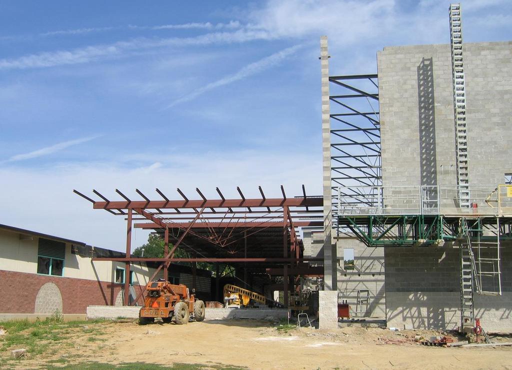
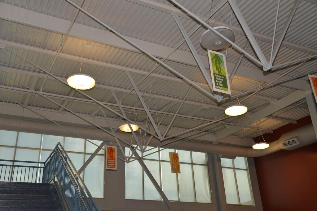
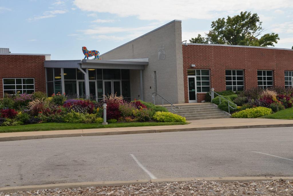
9 Heman Park Recreation Center Addition University City, Missouri Jacobs Engineering Architects and Structural
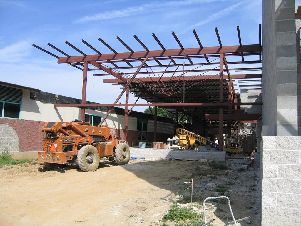
10
11
12
13
14
15
16 Kemper Art Museum Washington University in St. Louis Maki & Associates, Architects Jacobs Engineering, Structural

17
18
19
20 Steel Beam Using C b values

21 Using C b Values The Architect asks the structural engineer to design a roof beam to be as small and as unobtrusive as possible.
22 Using C b Values Roof beam: DL=20 psf, LL=20 psf span = 45 feet spacing = 14 feet assume 80 plf for beam weight For deflection (ASD loads) SIMPLE SPAN w(beam) DL+LL = 14(20+20) + 80 = 640 plf w (beam) LL = 14(20) = 280 plf I x (req d) for L/240 = 905 in 4 I x (req d) for L/360 = 594 in 4 For deflection, Use W21x48, I x =969 in 4 ; Z x =107 in 3 For Strength LRFD SIMPLE SPAN w u (beam) = 1.2(14(20)+80)+1.6(14(20)) = 880 plf M u = w u L 2 /8 = 222,750 ft-lbs Use Fy=50 ksi Z x (req d) = 59.4 in 3 No Good For Strength LRFD, choose W18x35, Z x =66.5 in 3 ; I x =513 in 4
23 Using C b Values Deflection controls. To reduce deflection, use fixed ends at the beams supports. This reduces the deflection to 1/5 th of its simple span value. Now, I x (req d) for L/240 = 181 in 4 I x (req d) for L/360 = 119 in 4 For deflection, choose W14x22, I x =199 in 4 ; Z x = 33.2 in 3 This reduces the moment to 2/3 s of its simple span value. Now, M u = w u L 2 /12 = 148,500 ft-lbs Z x (req d) = 39.6 in 3 For Strength LRFD, choose W14x26, Z x = 40.2 in 3 ; I x =246 in 4 Use W14x26?? THIS ASSUMES THE BEAM IS FULLY BRACED WRONG! (?)
24 Using C b Values Try to use a W14x26 with Fixed End Moment connections. Need to be concerned about STRENGTH (for beams that s shear and moment strength) STABILITY (is the beam braced?) SERVICEABILITY (for beams that s deflection) Moment strength (beam braced) and deflection have been accounted for. What about Shear and Stability? And what about (gasp!) Cost?
25 Using C b Values What about Cost? Well, put your money where your mouth, or your design, is. What about Shear? Shear rarely controls steel beam design only on short span, heavily loaded beams. What about Stability? Aye, there s the rub! Stability. Right now we have a W14x26 beam that s been designed as though it was completely braced. Is it? Is it braced, that is?
26 Using C b Values The top flange is braced by the metal deck welded to the top of the beam. More importantly, the compression flange is braced, if the compression is, indeed, at the top. What if the compression flange is at the bottom? Remember, compression is our enemy we need to brace the beam so the compression flange doesn t buckle. More about that later.
27 Using C b Values 0 0 Our FIRST design, W21x48, a simple span beam, allowed rotation at the ends, so the end moments were zero. In this case the moment is Positive along the entire length of the beam. Compression is on the side of the graph the TOP, in this case. A positive moment has compression on top of the beam. Compression is our enemy brace the top flange, where the compression is.
28 Using C b Values Deck at the top braces the beam. 0 0 Inflection Point (M=0) Nothing braces the bottom of the beam. Nothing braces the bottom of the beam. Our second design, W14x26 (BRACED), a fixed-end beam, had the end moments as negative, with compression on the bottom. In this case the compression is on the bottom at the end portions of the beam, and compression is at the top for the center portion of the beam. A positive moment has compression on top of the beam, and a negative moment has compression at the bottom of the beam.
29 Using C b Values So, we should (or could) brace the bottom flange of the beam: Well, maybe not.
30 Using C b Values So, The beam is unbraced what happens? Beams (members in bending or flexure) will reach their maximum capacity in one of three ways: 1) Unbraced beams: Failure by Elastic Lateral-Torsional Buckling 2) Partially braced: Failure by Inelastic Lateral-Torsional Buckling 3) Fully braced beams: Failure by complete inelastic material yielding.
31 Using C b Values 1) Unbraced beams: Failure by Elastic Lateral-Torsional Buckling Elastic: will return to its previous shape/orientation when load is removed looks fine. Buckles before any part of the section yields Fails at low stress we don t get all we paid for Lateral: compression flange moves sideways. Torsional: entire section twists. This is a stability failure, not a strength failure.
32 Using C b Values 2) Partially braced: Failure by Inelastic Lateral-Torsional Buckling Inelastic: will NOT return to previous shape/orientation when load is removed it s BENT Buckles after some part of the section yields Fails at a yield stress occurs, but only a part of the section has yielded. We STILL don t get all we paid for. Lateral: compression flange moves sideways. Torsional: entire section twists. This is mostly a stability failure, but strength is involved.
33 Using C b Values 3) Fully braced beams: Failure by complete inelastic material yielding. Complete: the entire section has yielded. Completely Inelastic: REALLY BENT. Develops the maximum capacity of the section. We get our money s worth. Best bag for the buck.
34 Using C b Values What does it mean to get our money s worth with braced beams? We can use a smaller, lighter, and more economical beam. That alone has value it helps us stay within budget, and saves money for non-structural uses. These values apply to non-aesthetic uses primarily non-exposed structures. And, At the same time, we have a greater choice of sections to use, and we can either use shallower or more slender shapes, which may be enhance the aesthetic value for exposed structures. So we want to brace our beams. Don t we?
35 Using C b Values What constitutes BRACING? WHAT do we brace? And how do we do it? With beams, we need to stop the twist : Assuming vertical loads (gravity): Grab the top & bottom of the beam, & stop the beam from twisting.
36 Using C b Values What constitutes BRACING? WHAT do we brace? And how do we do it? With beams, we need to stop the twist : Assuming vertical loads (gravity): Grab the top & bottom of the beam, & stop the beam from twisting. { moving sideways is OK just don t twist}
37 Using C b Values What constitutes BRACING? Bracing has to have a certain STRONG: +/- 1% of compression force. Bracing has to have a certain STIFFNESS often overlooked. Long braces tend to NOT have stiffness, especially in compression. Try to keep braces short and fat. To get more stiffness, keep braces as short as possible (L), and then large enough (A) to maintain their stiffness. Look at L(length) and A(area) D=movement=(NON-stiffness) D= PL AE
38 Using C b Values What constitutes BRACING? Bracing can be torsional composite steel beams with a concrete slab can have the BOTTOM FLANGE braced torsionally by the concrete slab at the TOP of the beam.
39 Using C b Values With metal deck AND with compression on the BOTTOM, the bottom moves sideways and causes the beam to twist. Lateral-Torsional Buckling will occur there s very little to stop the twist. There s nothing to stop the twist.
40 Using C b Values With metal deck AND with compression on the BOTTOM, the bottom moves sideways and causes the beam to twist. Lateral-Torsional Buckling will occur there s very little to stop the twist a stiffener plate will NOT brace the beam by itself. There s nothing to stop the twist.
41 C b uses and values It looks like our beam is UNBRACED, and we will have to design in that way. Here are the equations we need to go through:
42 C b uses and values And these:
43 C b uses and values C b ONLY applies when the beam is UNBRACED. There is NO C b for braced beams.
44 C b uses and values
45 C b uses and values Forget the formulas (EXCEPT, perhaps for C b ) All we need is the moment to be resisted, and the length between braced points on the beam huh? I thought we were unbraced! First of all, our LRFD maximum moment, M u = w u L 2 /12 = ft-kips The beam is braced at each bearing end, at each connection we have to be sure of that. So, the distance between braced points would be from one end of the beam to the other, which equals the span, so the distance between braces would be 45 feet.

46 C b uses and values Forget the formulas (EXCEPT, perhaps for C b ) Assuming the beam is Braced at 22-6 at midspan. This does NOT check For deflection. Only for moment strength and stability.

47 C b uses and values Forget the formulas (EXCEPT, perhaps for C b ) Assuming the beam is Braced at 22-6 at midspan. This does NOT check For deflection. Only for moment strength and stability. W10x49 OK Mcapacity = 176 ft-k OK HERE w/ fixity, We needed I x = 181 in 4
48 Using C b Values Deck at the top braces the beam feet 26 feet 0 0 Inflection Point (M=0) Nothing braces the bottom of the beam. Nothing braces the bottom of the beam. Is the inflection point a braced point? Is the beam braced where the inflection point occurs? Can the beam twist at that location? NO, NO, NO, NO, NO. The inflection point is NOT a braced point. Our unbraced length is 45 feet.
49 C b uses and values We need a moment capacity (LRFD, ΦMn = ft-kips) and an I x (req d) for L/240 = 181 in 4 USING C b = 1.0 W10x68 ΦMn = ft-kips Ix = 394 in 4 OK W12x65 ΦMn = ft-kips Ix = 533 in 4 OK W14x68 ΦMn = ft-kips Ix = 723 in 4 OK W16x67 ΦMn = ft-kips Ix = 954 in 4 OK W18x76 ΦMn = ft-kips Ix = 1,330 in 4 OK W21x83 ΦMn = ft-kips Ix = 1,830 in 4 OK
50 C b uses and values What C b should we use?
51 C b uses and values What C b should we use? For our beam, M max = 148.5; M A =M=18.56; M B =74.25 ft-kips C b = < 3.0 maximum (in the Commentary) Using the absolute values of the moments
52 C b uses and values What C b should we use? Check the Commentary:
53 C b uses and values What C b should we use? For top of the beam loading, multiply by C b = x (0.714 for top loading) = 1.70 Using the absolute values of the moments
54 C b uses and values We need a moment capacity (LRFD, ΦMn = ft-kips) and an I x (req d) for L/240 = 181 in 4 USING C b = x 2.38 = 1.70 W10x39 ΦMn = ft-kips Ix = 209 in 4 OK W12x40 ΦMn = ft-kips Ix = 310 in 4 OK W14x43 ΦMn = ft-kips Ix = 428 in 4 OK W16x50 ΦMn = ft-kips Ix = 659 in 4 OK W18x50 ΦMn = ft-kips Ix = 800 in 4 OK W21x57 ΦMn = ft-kips Ix = 1,170 in 4 OK
55 C b uses and values What C b should we use? For our beam, M 1 = 148.5; M 0 =148.5; M CL =74.25 ft-kips C b = 3.0 This requires that the top flange be braced!! Which it is. Does this make sense?
56 C b uses and values We need a moment capacity (LRFD, ΦMn = ft-kips) and an I x (req d) for L/240 = 181 in 4 USING C b = 3.0 W10x39 ΦMn = ft-kips Ix = 209 in 4 OK W12x30 ΦMn = ft-kips Ix = 238 in 4 OK W14x30 ΦMn = ft-kips Ix = 291 in 4 OK W16x31 ΦMn = ft-kips Ix = 375 in 4 OK W18x35 ΦMn = ft-kips Ix = 510 in 4 OK W21x44 ΦMn = ft-kips Ix = 843 in 4 OK
57 C b uses and values Beginning design: Next design: Next design: W21x48 Simple Span W14x26 Fixed Ends, assumed fully braced W10x49 Fixed Ends, braced at mid-span Next design: W12x65 Fixed Ends, unbraced, C b =1.00 Next design: W10x39 Fixed Ends, unbraced, C b =1.70 Next design: W12x30 Fixed Ends, unbraced, C b =3.00 W14x30 Fixed Ends, unbraced, C b =3.00
58 C b uses and values Column/Beam analogy: Why does a beam want to buckle? And what is the C b doing? These are columns, all carrying 100 kips at the base. Which one will want to buckle first? The first column, with a constant axial load, is the worst case.
59 C b uses and values Column/Beam analogy: What is the worst case for a beam? It is a constant compression force throughout the length of the beam. We accomplish this by placing concentrated moments at each end of the beam as shown. THIS IS = C b 1.0
60 C b uses and values Our actual Fixed-End Beam Forces. This is NOT C b = 1.0

61 C b uses and values With uplift (wind, probably) on a beam braced on top, all compression is on the bottom. The rods will buckle, and the top chord member is on its own! Use a C b = 2.00
62 C b uses and values

63 C b uses and values
64 C b uses and values
65 Using C b Values Roof beam: Check the W14x26 beam with WIND UPLIFT Uplift Wind = LL=10 psf net uplift span = 45 feet spacing = 14 feet For Strength LRFD SIMPLE SPAN (Conservative) w u (beam) = 1.6(14(10)) = 224 plf M u = w u L 2 /8 = 56,700 ft-lbs Use Fy=50 ksi Unbraced beam design, L u =45 feet, C b =2.0 ΦM n = 58,940 ft-pounds OK
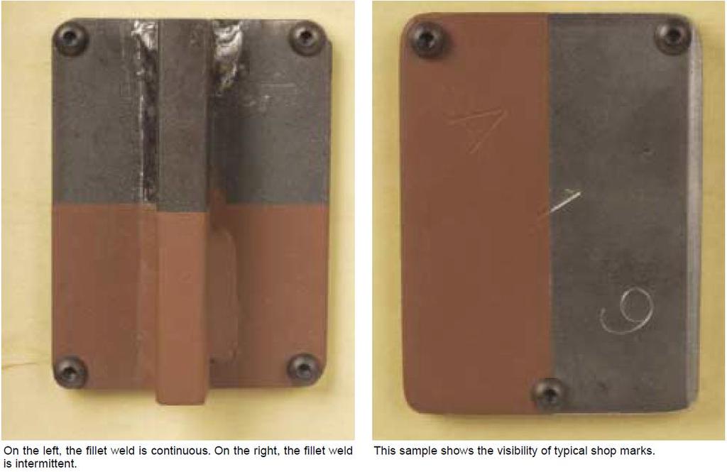
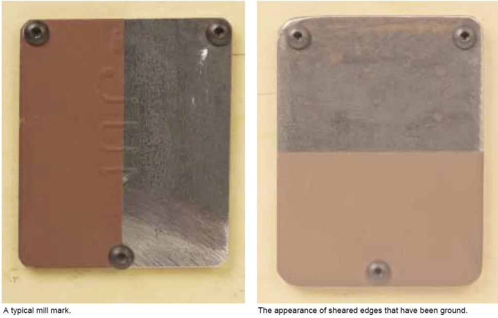
66 AESS Architecturally Exposed Structural Steel
67
68
69
70
71
72
73 AESS Architecturally Exposed Structural Steel The new (2016?) AISC Specification (the Steel Code) Will require that the connection design is NOT to be left up to the contractor. The SEOR shall design all AESS connections. The Architect and the engineer will need to determine what type of connections are appropriate and desirable. double angle / single plate / moment / welded / bolted / welded and bolted / the sky s the limit BUT the control of the connections appearance needs to be in the hands of the designers.
74 C b uses and values QUESTIONS?
James Hauck 1 and Christine Moe 2
 3479 Beam-over-Column Bracing Requirements in Continuous Steel Frame Buildings James Hauck 1 and Christine Moe 2 1 Associate Principal, Wiss, Janney, Elstner Associates, Inc., 10 South LaSalle Street,
Name: 1 FOR ANY AISC DESIGN AIDS: YOU MUST SPECIFY THE TABLE USED. CE311 Fall 2017 Exam 3 11/16/2017. ASD Load Combinations: LRFD Load Combinations:
 CE 311 Celebration of Knowledge 3 100 points November 16, 2017, 7pm to 9:30pm YOU MUST CITE ANY AISC DESIGN AIDS USED You are allowed to have the AISC manual, and a calculator. Given Formulae: Live Load
Case Study in Steel adapted from Structural Design Guide, Hoffman, Gouwens, Gustafson & Rice., 2 nd ed.
 Case Study in Steel adapted from Structural Design Guide, Hoffman, Gouwens, Gustafson & Rice., 2 nd ed. Building description The building is a one-story steel structure, typical of an office building.
2016 AISC Standards. Specification for Structural Steel Buildings & Code of Standard Practice for Steel Buildings and Bridges.
 2016 AISC Standards Specification for Structural Steel Buildings & Code of Standard Practice for Steel Buildings and Bridges Eric Bolin Staff Engineer June 1, 2017 2016 AISC Standards 2018 INTERNATIONAL
twenty one Steel Construction 1 and design APPLIED ARCHITECTURAL STRUCTURES: DR. ANNE NICHOLS SPRING 2018 lecture STRUCTURAL ANALYSIS AND SYSTEMS
 APPLIED ARCHITECTURAL STRUCTURES: STRUCTURAL ANALYSIS AND SYSTEMS DR. ANNE NICHOLS SPRING 2018 lecture twenty one steel construction http://nisee.berkeley.edu/godden and design Steel Construction 1 Steel
Devil is in the Details. Brian Crowder, P.E.
 Devil is in the Details Brian Crowder, P.E. Food for Thought Does the alternate load path analysis using linear-elastic techniques provide an accurate prediction of the response of the structure under
Whose responsibility is it? Design Responsibility. Steel Joist Institute. Standard Assumptions. Common Pitfalls in Steel Joist Specification
 Common Pitfalls in Steel Joist Specification Whose responsibility is it? Joist supplier? Steel fabricator? Contractor? Other trades? Specifier? Design Responsibility Joist Supplier s responsibilities include
STEEL REACTION FRAME
 STEEL REACTION FRAME Kyle Coleman, CEE Laboratory Manager Andrew Myers, Assistant Professor Jerome F. Hajjar, Professor and Chair, Director, STReSS Laboratory Department of Civil and Environmental Engineering,
The problems in this guide are from past exams, 2011 to 2016.
 CE 311 Exam 1 Past Exam Problems, 2011 to 2016 Exam 1 (14% of the grade) THURSDY, 9/21 7 TO 9:30PM. OPTIONL Q& SESSION WED. 9/20, 8PM. COVERGE: LESSONS 1 TO 9 Exam is designed for 2 hours, but a maximum
AISC Live Webinars. Thank you for joining our live webinar today. We will begin shortly. Please standby.
 AISC Live Webinars Thank you for joining our live webinar today. We will begin shortly. Please standby. Thank you. Need Help? Call ReadyTalk Support: 800.843.9166 Today s audio will be broadcast through
Steel Design Guide Series. Steel and Composite Beams with. Web Openings
 Steel Design Guide Series Steel and Composite Beams with Web Openings Steel Design Guide Series Steel and Composite Beams with Web Openings Design of Steel and Composite Beams with Web Openings David Darwin
Steel Beam Analysis and Design
 Architecture 324 Structures II Steel Beam Analysis and Design Steel Properties Steel Profiles Steel Codes: ASD vs. LRFD Analysis Method Design Method University of Michigan, TCAUP Structures II Slide 1/35
Tech Tips SidePlate Connections FAQ 09/30/2017
 Tech Tips SidePlate Connections FAQ 09/30/2017 Page 1 of 15 Introduction to SidePlate Connection Technology SidePlate Connection Technology is ideally suited to protect structures against seismic events,
The 2008 AISI Cold-formed Steel Design Manual
 Missouri University of Science and Technology Scholars' Mine International Specialty Conference on Cold- Formed Steel Structures (2010) - 20th International Specialty Conference on Cold-Formed Steel Structures
Structural Engineering, Mechanics, and Materials. Preliminary Exam - Structural Design
 Fall Semester 2018 Preliminary Exam - Structural Design A small building is located in downtown Berkeley. The structural system, either structural steel or reinforced concrete, comprises gravity framing
Beam Design and Deflections
 Beam Design and Deflections Criteria for Design Allowable normal stress or normal stress from LRFD should not be exceeded: Knowing M and F b, the minimum section modulus fitting the limit is: F or φf b
fifteen steel construction: materials & beams ARCHITECTURAL STRUCTURES: FORM, BEHAVIOR, AND DESIGN DR. ANNE NICHOLS SUMMER 2016 lecture
 ARCHITECTURAL STRUCTURES: FORM, BEHAVIOR, AND DESIGN DR. ANNE NICHOLS SUMMER 2016 lecture fifteen steel construction: materials & beams Steel Beams 1 Steel Beam Design American Institute of Steel Construction
Design of Steel Joists and Roof Decks
 Design of Steel Joists and Roof Decks Michael R. Miller, P. E. Topics for Discussion Design Responsibility What is a standard joist? Assumptions Dimensions Designations Joist Design for Wind Uplift Properly
MECHANICAL BRIDGING AND BRIDGING ANCHORAGE OF LOAD BEARING COLD-FORMED STEEL STUDS. Paul E. Lackey, EIT Nabil A. Rahman, Ph.D.
 INTRODUCTION MECHANICAL BRIDGING AND BRIDGING ANCHORAGE OF LOAD BEARING COLD-FORMED STEEL STUDS Paul E. Lackey, EIT Nabil A. Rahman, Ph.D., PE Gary Bennett The purpose of this technical note is to provide
How Loads Are Distributed
 LOAD DISTRIBUTION 1 LOAD DISTRIBUTION This section illustrate how load will transmit from the deck to the stringers. Determining the fraction of load carried by a loaded member and the remainder distributed
AASHTOWare BrDR 6.8 Steel Tutorial STL6 Two Span Plate Girder Example
 AASHTOWare BrDR 6.8 Steel Tutorial STL6 Two Span Plate Girder Example STL6 - Two Span Plate Girder Example (BrDR 6.5) 1'-6" 37'-0" 34'-0" 1'-6" 8 1/2" including 1/2" integral wearing surface FWS @ 25 psf
Steel Column Analysis and Design
 Architecture 324 Structures II Steel Column Analysis and Design Failure Modes Effects of Slenderness Stress Analysis of Steel Columns Capacity Analysis of Steel Columns Design of Steel Columns University
SJI Updates Expanded Load Tables for Noncomposite Joists / Joist Girders and Development of New Composite Joist Series
 SJI Updates Expanded Load Tables for Noncomposite Joists / Joist Girders and Development of New Composite Joist Series SUMMARY David Samuelson Steel joists are growing in recognition as being a very economical
Structural Technical Report 1 Structural Concepts / Structural Existing Conditions Report
 Michael A. Troxell Structural Option Advisor: Professor Parfitt College of Business Administration Oct. 5, 2005 Structural Technical Report 1 Structural Concepts / Structural Existing Conditions Report
Lateral Design of Mid- Rise Wood Structures
 Lateral Design of Mid- Rise Wood Structures Presented by Ricky McLain, MS, PE, SE Technical Director WoodWorks Texas Workshops December, 2016 Insert picture of me graduating college Follow the load Following
Project ULA 120D Snow-0 Seis-IV
 ULA Geometry Module Specification Sub-Array Configuration ULA Totals # Rows: 4 Column N-S Length (in): 6 # SubArrays: N-S Dim (in): 40 N-S Spacing (in): 0.25 # Columns: 5 Array E-W Dimension (in): 326
IF SECOND-ORDER EFFECTS NEED TO BE CONSIDERED ON THIS EXAM, ASSUME A B1 MOMENT-MAGNIFIER OF 1.05.
 Name: Cack Zoleman CE311 FINAL EXAM Tuesday, December 12, 2017, 8am to Noon, Room 200 You may use the Steel Manual, Calculator, Drawing Supplies, only 100 points Given Steel Properties: E = 29000 ksi,
COMPARISON OF STRUCTURAL STEEL LATERAL FORCE RESISTING SYSTEMS FOR A THEORETICAL HOSPITAL GRID SYSTEM GRANT BUELL. B.S., Kansas State University, 2009
 COMPARISON OF STRUCTURAL STEEL LATERAL FORCE RESISTING SYSTEMS FOR A THEORETICAL HOSPITAL GRID SYSTEM by GRANT BUELL B.S., Kansas State University, 2009 A REPORT submitted in partial fulfillment of the
W. Mark McGinley March 3, 2016 ISEA MEETINGS 1
 J.B. SPEED SCHOOL OF ENGINEERING Design of s for Masonry Veneers W. Mark McGinley, Ph. D., PE FASTM MASONRY DAY Indianapolis March 3, 2016 Objectives Present a Brief Overview of: Masonry Veneer Wall systems
THE PLAZA AT PPL CENTER ALLENTOWN, PA
 : MOMENT FRAME COMPARISON Introduction Design Intent IBC 2000 and ASCE 7-98 recognizes steel frames designed with a response modification factor, R, less than or equal to three as structural steel systems
Design of Short Span Steel Bridges
 PDHonline Course S122 (3 PDH) Design of Short Span Steel Bridges Instructor: Frank Russo, Ph.D. & John C. Huang, Ph.D., PE 2012 PDH Online PDH Center 5272 Meadow Estates Drive Fairfax, VA 22030-6658 Phone
Learning Objectives. Topics. Moment Frames: Design and Detailing per AISC 341 and 358. Topics. Lateral Analysis/Choosing your Code
 Topics Moment Frames: Design and Detailing per AISC 341 and 358 By Matthew J. Mester, PE, SE SidePlate Systems, Inc. SE University, June, 2017 www.learnwithseu.com 2 Learning Objectives Topics Identify
SE APPRENTICE. Today s Speakers. Lateral Load Systems. Lateral Loads
 Today s Speakers Carrie Bremer, PE Schaefer Stephen Metz, PE SMBH, Inc. Today s Moderators SE APPRENTICE Lecture Two- Systems & Paths Lisa Willard, PE SE Solutions, LLC SE Apprentice Brian Quinn, PE SE
Structural Technical Report 1 Structural Concepts / Existing Conditions
 Chris Shelow Structural Advisor: M. Kevin Parfitt Koshland Integrated Natural Science Center 10/05/05 AE 481W Structural Technical Report 1 Structural Concepts / Existing Conditions Executive Summary The
AISC Live Webinar. AISC Live Webinars. Need We will Help? begin shortly. Please standby.
 AISC Live Webinars Thank you for joining our live webinar today. We will begin shortly. Please standby. AISC Live Webinars Thank Thank you. you for joining our live webinar today. Need We will Help? begin
Composite Steel/Concrete
 Composite Steel/Concrete Composite Steel and Concrete Clinton O. Rex, P.E., PhD Originally developed by James Robert Harris, P.E., PhD, and Frederick R. Rutz, P.E., PhD Disclaimer Instructional Material
Question 8 of 55. y 24' 45 kips. 30 kips. 39 kips. 15 kips x 14' 26 kips 14' 13 kips 14' 20' Practice Exam II 77
 Question 8 of 55 A concrete moment frame building assigned to SDC = D is shown in the Figure. Equivalent lateral force analysis procedure is used to obtain the seismic lateral loads, E h, as shown. Assume
LESSON 8: COLUMN BUCKLING I
 "lways, there is football." Cristal Choi, former exchange student who lived in Prof. Kurtz s house, explaining all merican holidays to a new exchange student. LESSON 8: COLUMN BUCING I Wednesday, September
Lightweight Steel Framing. Composite DeltaStud Load Tables
 Lightweight Steel Framing Composite DeltaStud Load Tables January 2011 TABLE OF CONTENTS Introduction and Scope...3 Design Responsibility...3 Design Criteria and Technical Data...3 Composite Action / Materials
AISC Live Webinars. Thank you for joining our live webinar today. We will begin shortly. Please standby.
 ! The Most Common Source of AISC Live Webinars Thank you for joining our live webinar today. We will begin shortly. Please standby. Thank you. Need Help? Call ReadyTalk Support: 800.843.9166 AISC Live
Check the strength of each type of member in the one story steel frame building below.
 CE 331, Summer 2015 nalysis of Steel Braced Frame Bldg 1 / 9 Check the strength of each type of member in the one story steel frame building below. 4 @ 8 ft B 20 f 1 2 3 @ 25 ft Side Elevation 3 4 Plan
BERRIDGE SPACEFRAME BUILDING COMPONENTS DESIGN GUIDE
 BERRIDGE SPACEFRAME BUILDING COMPONENTS DESIGN GUIDE CONTENTS PROPERTIES & LOADS 24 Ga. Stud Properties & Loads... 2 Back to Back Stud Properties & Loads... 2 C-Channel Rafter Properties & Loads... 3 Load
TECHNICAL NOTE HEADER DESIGN. On Cold-Formed Steel Construction INTRODUCTION BOX HEADERS $5.00
 TECHNICAL NOTE On Cold-Formed Steel Construction 1201 15th Street, NW, Suite 320 W ashington, DC 20005 (202) 785-2022 $5.00 HEADER DESIGN Summary: The Standard for Cold-Formed Steel Framing - Header Design
Investigation of Structural Steel Webs for Punching Shear
 Journal of Civil Engineering and Architecture 9 (2015) 1126-1136 doi: 10.17265/1934-7359/2015.09.013 D DAVID PUBLISHING Investigation of Structural Steel Webs for Punching Shear Mustafa Mahamid 1 and Adeeb
Lightweight Steel Framing. DeltaStud Load Tables
 Lightweight Steel Framing DeltaStud Load Tables January 2013 Roger A. LaBoube, Ph.D, P.E. The load tables and technical information contained in this catalogue were prepared by Dr. Roger A. LaBoube, Ph.D,
John Jay College Expansion Project
 Technical Report #3 Michael Hopper Mike AE Consultant: Dr. Lepage [Type the company name] November 21 st, 2008 Technical Report #3 Table of Contents Executive Summary.3 Introduction.4 Existing Composite
There are countless ways to improve constructability on your next project. Here are 50 of them. the need for it or specify it on the design drawings.
 There are countless ways to improve constructability on your next project. Here are 50 of them. Tips to Take your Team to the Top By Matthew D. Brady, P.E., and Cliff Schwinger, P.E. We hear the word constructability
80 Fy (ksi)= 50 2 nd Floor = 61. Length (ft) Plan View. Penthouse
= 50 2 nd Floor = 61. Length (ft) Plan View. Penthouse") SUBJECT: CORNER SHEET 62 of 131 Design Columns for the lightest W10's and W12's section. Columns are to be sized for two options: Option I Continuous, Option II with Splices. Then prices are to be compared
SUBJECT: CORNER SHEET 62 of 131 Design Columns for the lightest W10's and W12's section. Columns are to be sized for two options: Option I Continuous, Option II with Splices. Then prices are to be compared
Design- Lateral System:
 Design- Lateral System: Investigation: When considering the design of the lateral load resisting system, first a look was taken at the existing shear walls. The existing lateral system in The Lexington
Study Guide. Given Formulae:
 E311 EXM 1 STUDY GUIDE Exam 1 Date: Thursday, September 21 st, 2017, 7 to 9:30pm This Guide Last Updated on ugust 21 st, 2017 Study Guide This study guide compliments the Past Exam Problems. Students should
50 Tips for Designing Steel Framed Buildings September 27, AISC Live Webinar. AISC Live Webinars
 AISC Live Webinars 1 Thank you for joining our live webinar today. We will begin shortly. Please standby. AISC Live Webinars Thank Thank you. you for joining our live webinar today. Need We will Help?
Fundamentals of Wood Design and Engineering
 Fundamentals of Wood Design and Engineering Session 3 Wood Design Introduction to Wood Engineering; Codes & Standards; Load combinations, weights of building materials and tributary area; Simple beam design:
Software Verification
 EXAMPLE 9 ACI Handbook Two-Way Slab Example 2 PROBLEM DESCRIPTION The two-way slab system arranged three-by-three is shown in Figure 9-1. The slab consists of nine 6.5-inch-thick 20-foot 24-foot panels.
ISSUE A Code Change # 2 Class 3 and Class 4 Buildings
 ISSUE A Code Change # 2 Class 3 and Class 4 Buildings (new) Section 1604.9 Disproportionate Collapse. Design for structural integrity of new buildings to protect against disproportionate collapse shall
Multi-Story Solid Tilt-Up Wall Panel Analysis and Design (ACI 551)
") Multi-Story Solid Tilt-Up Wall Panel Analysis and Design (ACI 551) Span 1 Span 2 Span 3 Span 4 Reinforced Concrete Multi-Story Tilt-Up Wall Panel Analysis (ACI 551) Tilt-up is form of construction with
Multi-Story Solid Tilt-Up Wall Panel Analysis and Design (ACI 551) Span 1 Span 2 Span 3 Span 4 Reinforced Concrete Multi-Story Tilt-Up Wall Panel Analysis (ACI 551) Tilt-up is form of construction with
VARIOUS TYPES OF SLABS
 VARIOUS TYPES OF SLABS 1 CHOICE OF TYPE OF SLAB FLOOR The choice of type of slab for a particular floor depends on many factors. Economy of construction is obviously an important consideration, but this
four design methods & beams APPLIED ACHITECTURAL STRUCTURES: DR. ANNE NICHOLS FALL 2018 lecture STRUCTURAL ANALYSIS AND SYSTEMS ARCH 631
 APPLIED ACHITECTURAL STRUCTURES: STRUCTURAL ANALYSIS AND SYSTEMS DR. ANNE NICHOLS FALL 2018 lecture four design methods & beams Forum, Pompeii Methods & Beams 1 Allowable Stress Design historical method
Lateral Buckling of I-joists
 Lateral Buckling of I-joists Daniel P. Hindman Assistant Professor Department of Wood Science and Forest Products, Virginia Tech Blacksburg, VA, USA Summary Previous researchers have studied the lateral
Supplemental Structural Correction Sheet Steel Moment Frame Design (2017 LABC)
") Supplemental Structural Correction Sheet Steel Moment Frame Design (2017 LABC) Plan Check/PCIS Application No.: Checked By: Your feedback is important, please visit our website to complete a Custom Survey
Supplemental Structural Correction Sheet Steel Moment Frame Design (2017 LABC) Plan Check/PCIS Application No.: Checked By: Your feedback is important, please visit our website to complete a Custom Survey
CURVED STEEL I GIRDER BRIDGES RAMP GH OVER THE ERIE CANAL INTRODUCTION BEHAVIOR OF CURVED BRIDGES DIFFERENCES FROM STRAIGHT BRIDGES
 DIFFERENCES FROM STRAIGHT BRIDGES Torsion effects Flange lateral bending Global stability CURVED STEEL I GIRDER BRIDGES RAMP GH OVER THE ERIE CANAL Constructability concerns INTRODUCTION COMPARISON WITH
30 kip/ft (Dead load) 5 ft. 20 ft
 5 ft. 20 ft") UNIVERSITY OF CALIFORNIA, BERKELEY Dept. of Civil and Environmental Engineering Spring Semester 2017 Structural Engineering, Mechanics and Materials Ph.D. Preliminary Examination: Design Consider the frame
UNIVERSITY OF CALIFORNIA, BERKELEY Dept. of Civil and Environmental Engineering Spring Semester 2017 Structural Engineering, Mechanics and Materials Ph.D. Preliminary Examination: Design Consider the frame
Length (ft) At 2. Penthouse At 3 (roof) : DL = 30 psf
 At 2. Penthouse At 3 (roof) : DL = 30 psf") SUBJECT: INTERIOR (underneath penthouse) SHEET 40 of 131 Design Columns for the lightest W10's and W12's section. Columns are to be sized for two options: Option I Continuous, Option II with Splices. Then
SUBJECT: INTERIOR (underneath penthouse) SHEET 40 of 131 Design Columns for the lightest W10's and W12's section. Columns are to be sized for two options: Option I Continuous, Option II with Splices. Then
Cross Frame Design for Curved and Skewed Bridges
 Cross Frame Design for Curved and Skewed Bridges Using AASHTO LRFD, 8 th Edition Travis Butz, PE To View Presentation on Your Mobile Device: www.burgessniple.com/event/2018/otec Cross frames in the 8 th
Learning Module Number 7 Second- order (P- Δ and P- δ) Effects
 Effects") Learning Module Number 7 Second- order (P- Δ and P- δ) Effects Overview Second- order effects in beam- columns are investigated. Results obtained using rigorous second- order elastic analyses are compared
Learning Module Number 7 Second- order (P- Δ and P- δ) Effects Overview Second- order effects in beam- columns are investigated. Results obtained using rigorous second- order elastic analyses are compared
FASTRAK Composite Beam Design
 Chk'd by 1 FASTRAK Calculation FASTRAK is a design tool for composite and non-composite beams with flexible loading options, design criteria, and stud optimization and placement. This powerful tool is
AISC Live Webinar. for joining our live webinar today. Need We will Help? begin shortly. Please standby. AISC Live Webinars
 AISC Live Webinars Thank you for joining our live webinar today. We will begin shortly. Please standby. AISC Live Webinars Thank you. for joining our live webinar today. Need We will Help? begin shortly.
four design methods & beams Allowable Stress Design Limit State Design Allowable Stress Design
 APPLIED ARCHITECTURAL STRUCTURES: STRUCTURAL ANALYSIS AND SYSTES DR. ANNE NICHOLS FALL 013 lecture four Allowable Stress Design historical method a.k.a. working stress, stress design stresses stay in ELASTIC
COMPOSITE CONCRETE FILLED HSS: DESIGN CONSIDERATIONS
 STEEL TUBE INSTITUTE HSS ENEWS PRIMARY ARTICLE OCTOBER 2016 COMPOSITE CONCRETE FILLED HSS: DESIGN CONSIDERATIONS JASON ERICKSEN, SE, FORSE CONSULTING, TECHNICAL CONSULTANT TO THE STEEL TUBE INSTITUTE Kim
Allowable Loads for Round Timber Poles
 UNIVERSITY OF ALASKA FAIRBANKS Allowable Loads for Round Timber Poles HCM-00752 UNIVERSITY OF ALASKA FAIRBANKS The following publication is a major upgrade of information for calculating and understanding
AASHTOWare BrR 6.8 Steel Tutorial Steel Plate Girder Using LRFR Engine
 AASHTOWare BrR 6.8 Steel Tutorial Steel Plate Girder Using LRFR Engine STL6 - Two Span Plate Girder Example 1'-6" 37'-0" 34'-0" 1'-6" 8 1/2" including 1/2" integral wearing surface FWS @ 25 psf 3'-6" 3
Technical Report 1. Seneca Allegany Casino Hotel Addition. Salamanca, NY
 Technical Report 1 Seneca Allegany Casino Hotel Addition Salamanca, NY Nicholas Reed Structural Option Advisor: Prof. Parfitt Executive Summary The purpose of this technical report was to analyze the existing
four design methods & beams APPLIED ACHITECTURAL STRUCTURES: DR. ANNE NICHOLS SPRING 2018 lecture STRUCTURAL ANALYSIS AND SYSTEMS ARCH 631
 APPLIED ACHITECTURAL STRUCTURES: STRUCTURAL ANALYSIS AND SYSTEMS DR. ANNE NICHOLS SPRING 2018 lecture four design methods & beams Forum, Pompeii Methods & Beams 1 Allowable Stress Design historical method
COUNTRY MUSIC HALL OF FAME & MUSEUM
 TECHNICAL ASSIGNMENT #2 Executive Summary Technical report #2 analyzes the viability of different structural materials in place of the structural steel that is used in the Country Music Hall of Fame &
GENERAL TOPICS & MEMBER DESIGN
 OVERVIEW GENERAL TOPICS & MEMBER DESIGN Manual Overview Specification Overview Scope Design Considerations Member Design OVERVIEW CONNECTION DESIGN 2010 Specification Bolts Welds Connecting Elements 14
Strategies for mitigation of progressive collapse of corner panels in reinforced concrete buildings
 Safety and Security Engineering II 161 Strategies for mitigation of progressive collapse of corner panels in reinforced concrete buildings O. A. Mohamed University of Hartford, Department of Civil, Biomedical
Structural Breadth. Cathedral Place Milwaukee, WI Steven Puchek Senior Thesis Project. Relationship with Thesis Project.
 Structural Breadth The structural breadth for this thesis was chosen late in development as a response to the use of a seemingly exorbitant cantilever at the ground floor of the building s lobby. Fully
AISC Live Webinars. Thank you for joining our live webinar today. We will begin shortly. Please standby.
 AISC Live Webinars Thank you for joining our live webinar today. We will begin shortly. Please standby. Thank you. Need Help? Call ReadyTalk Support: 800.843.9166 AISC Live Webinars Today s live webinar
JPods, LLC. Cost Estimate. Structural Support Systems. for 12/08/06 SHEET N 1 OF 16 CALC N
 1 OF 16 12/08/06 Cost Estimate of Structural Support Systems for JPods, LLC 2 OF 16 TABLE OF CONTENTS SUBJECT: PAGE 1. Purpose.. 3 2. Methodology. 3. 3. Assumptions. 4 4. Input Data... 5 5. Loading Combinations
RESTRAINED VS. UNRESTRAINED FIRE RATINGS: A PRACTICAL APPROACH
 RESTRAINED VS. UNRESTRAINED FIRE RATINGS: A PRACTICAL APPROACH Many structures have reserve strength capacity which can be utilized for resisting loads resulting from extraordinary events By Socrates A.
eight plates and grids Plates, Slabs & Grids Plates, Slabs & Grids Term Project plates horizontal plane, rigid slabs thin, flat, rigid
 APPLIED ARCHITECTURAL STRUCTURES: STRUCTURAL ANALYSIS AND SYSTEMS DR. ANNE NICHOLS SPRING 2018 Term Project lecture eight plates and grids Plates & Grids 1 Lecture 8 Applied Architectural Structures F2009abn
DIVISION: METALS SECTION: STEEL DECKING REPORT HOLDER: EPIC METALS CORPORATION 11 TALBOT AVENUE RANKIN, PENNSYLVANIA 15104
 0 Most Widely Accepted and Trusted ICC ES Evaluation Report ICC ES 000 (800) 423 6587 (562) 699 0543 www.icc es.org ESR 2047 Reissued 07/207 This report is subject to renewal 07/209. DIVISION: 05 00 00
Structural Glossary. ARCH 631 Structural Glossary F2014abn
 Structural Glossary Allowable strength: Nominal strength divided by the safety factor. Allowable stress: Allowable strength divided by the appropriate section property, such as section modulus or cross
Reinforced Concrete Tilt-Up Wall Panel with Opening Analysis and Design (ACI 551)
") Reinforced Concrete Tilt-Up Wall Panel with Opening Analysis and Design (ACI 551) Reinforced Concrete Tilt-Up Wall Panel with Opening Analysis and Design (ACI 551) Tilt-up is form of construction with
Reinforced Concrete Tilt-Up Wall Panel with Opening Analysis and Design (ACI 551) Reinforced Concrete Tilt-Up Wall Panel with Opening Analysis and Design (ACI 551) Tilt-up is form of construction with
STRUCTURAL ENGINEERING CALCULATIONS NEW WINDOW OPENING IN EXISTING PERIMETER LOAD BEARING WOOD FRAMED WALL Project Address: Job #: 80167
 4533 MacArthur Blvd., Ste A-2003 Newport Beach, CA 92660 949-478-4026 cell www.ocstructurecheck.com jeremy@ocstructurecheck.com STRUCTURAL ENGINEERING CALCULATIONS NEW WINDOW OPENING IN EXISTING PERIMETER
Executive Summary Building Description: Introduction... 13
 Table of Contents Executive Summary... 2 Building Description:... 2 Report Summary:... 2 Introduction... 3 Building Description:... 3 Current Framing Layout... 4 Report Topics:... 4 Loads and Load Cases...
Agricultural Hall and Annex East Lansing, MI. Structural Design. Gravity Loads. 1- Based on US Standards
 Structural Design Gravity Loads 1- Based on US Standards Occupancy or Use Uniform (psf) Concentrated (lbs) Office building -Office -Lobbies and first-floor corridors -Corridor above first floor -Partitions
LATERAL LOAD DEVELOPMENT 11 BRACED FRAME DESIGN 15 COLUMN, BEAM, FOOTING, CONNECTION, AND DIAGONAL DESIGN 22 COMPUTER ANALYSIS 28
 DIMITRY A. REZNIK STRUCTURAL OPTION ADVISOR: DR. MEMARI NORTHBROOK CORPORATE CENTER 03/31/2006 AE 482 SENIOR THESIS. CONTENTS EXECUTIVE SUMMARY 3 BUILDING DESCRIPTION 5 DESCRIPTION OF BUILDING S STRUCTURAL
One-Way Wide Module Joist Concrete Floor Design
 One-Way Wide Module Joist Concrete Floor Design A 1 3 4 30'-0" 30'-0" 30'-0" 3' B 3' C 3' D 3' E 4" 4" (typ.) 3' F 0" 0" (typ.) Figure 1 One-Way Wide Module Joist Concrete Floor Framing System 1 Overview
Analysis and Design of One-way Slab System (Part-I)
") Lecture-02 Analysis and Design of One-way Slab System (Part-I) By: Prof Dr. Qaisar Ali Civil Engineering Department UET Peshawar www.drqaisarali.com 1 Topics Addressed Concrete Floor Systems Analysis and
Lecture-02 Analysis and Design of One-way Slab System (Part-I) By: Prof Dr. Qaisar Ali Civil Engineering Department UET Peshawar www.drqaisarali.com 1 Topics Addressed Concrete Floor Systems Analysis and
AREMA 2008 Annual Conference. LOW PROFILE RAILROAD BRIDGE Steve K. Jacobsen, PE NNW, Inc. Rochester, Minnesota
 AREMA 2008 Annual Conference LOW PROFILE RAILROAD BRIDGE Steve K. Jacobsen, PE NNW, Inc. Rochester, Minnesota 55904 507-281-5188 Steve K. Jacobsen, PE 2 LOW PROFILE RAILROAD BRIDGE Steve K. Jacobsen, PE
Steel Joist Floor Systems Best Practices
 Steel Joist Floor Systems Best Practices APRIL 20, 2016 Copyright 2016 Steel Joist Institute. All Rights Reserved. Presented by: Michael A. West, P.E., F.ASCE David Samuelson, P.E. Learning Objectives
[TECHNICAL REPORT 3] Lateral System Analysis
![[TECHNICAL REPORT 3] Lateral System Analysis](/thumbs/96/126531717.jpg "[TECHNICAL REPORT 3] Lateral System Analysis") Science Center Research Park 3711 Market St. The Pennsylvania State University Department of Architectural Engineering Senior Thesis 2009-2010 Prepared by: November 30, 2009 [TECHNICAL REPORT 3] Lateral
Science Center Research Park 3711 Market St. The Pennsylvania State University Department of Architectural Engineering Senior Thesis 2009-2010 Prepared by: November 30, 2009 [TECHNICAL REPORT 3] Lateral
Basic Concepts. Introduction to Composite Design
 Introduction to Composite Design MORGAN STATE UNIVERSITY SCHOOL OF ARCHITECTURE AND PLANNING LECTURE IΧ Dr. Jason E. Charalambides Basic Concepts! What is a composite Beam? " Steel W-shape and portion
AISI S E1 AISI STANDARD. Errata to North American Specification. for the Design of Cold-Formed. Steel Structural Members.
 AISI S100-12-E1 AISI STANDARD Errata to North American Specification for the Design of Cold-Formed Steel Structural Members 2012 Edition Amendment on August 16, 2013 Errata to North American Specification
CH. 9 WOOD CONSTRUCTION
 CH. 9 WOOD CONSTRUCTION PROPERTIES OF STRUCTURAL LUMBER Grading Load carrying capacity effected by: - Size and number of knots, splits & other defects - Direction of grain - Specific gravity of wood Grading
midas Gen MIDAS On-Demand Service midas Gen Advanced Webinar Steel Structure Design
 midas Gen midas Gen Advanced Webinar Steel Structure Design 1 midas Why Gen midas Gen Integrated Design System MIDAS for buildings On-Demand General Service Structures Versatility Specialty Structures
Design Parameters
 Page 1 of 10 2.4.1.2 Design Parameters The program contains a large number of parameter names which are needed to perform designing and code checking. These parameter names, with their default values,
Brent Ellmann Structural Option 200 Minuteman Park, Andover, MA Structural Consultant: Dr. Hanagan
 Structural Design: Goals: The original design of 200 Minuteman Drive was dictated largely by Brickstone Properties, the building s owner. The new design of 200 Minuteman Drive, with additional floors,
ANALYSIS AND DESIGN OF MOMENT RESISTING MIDWALL BY THE STEEL NETWORK, INC.
 ANALYSIS AND DESIGN OF MOMENT RESISTING MIDWALL BY THE STEEL NETWORK, INC. Paul Lackey, P.E., Muhammad Ghoraba, Nabil A. Rahman, Ph.D., P.E. and Kurtis Kennedy MidWall is a hold-down product intended to
Lectures Notes (Steel I - CT122) Higher technological institute 10 th of Ramadan city Dr. Essam Abd Elaty Mohamed Amoush.
 Higher technological institute 10 th of Ramadan city Dr. Essam Abd Elaty Mohamed Amoush.") Introduction A truss is a structural system constructed of linear members forming triangular patterns. The members are assumed to be straight and connected to one another by frictionless hinges. All loading
Introduction A truss is a structural system constructed of linear members forming triangular patterns. The members are assumed to be straight and connected to one another by frictionless hinges. All loading