BEARING CAPACITY OF SHALLOW FOUNDATIONS
|
|
|
- Meryl Wilkinson
- 6 years ago
- Views:
Transcription

 is the load that causes the shear failure of the soil underneath and adjacent to the footing.")
1 BEARING CAPACITY OF SHALLOW FOUNDATIONS Introduction A foundation, often constructed from concrete, steel or wood, is a structure designed to transfer loads from a superstructure to the soil underneath the superstructure. In general, foundations are categorized into two groups, namely, shallow and deep foundations. Shallow foundations are comprised of footings, while deep foundations include piles that are used when the soil near the ground surface has no enough strength to stand the applied loading. The ultimate bearing capacity, qu,(in kpa) is the load that causes the shear failure of the soil underneath and adjacent to the footing. In this chapter, we will discuss equations used to estimate the ultimate bearing capacity of soils. Bearing Failure Modes (a) (b) (c) Figure 1: Modes of bearing failures (a) General shear (b) Local shear and (c) Punching shear. 1
2 Relative density of the soil and size of the foundation are among the major factors that affect the mode of bearing failure likely to occur. The modes of bearing failure are generally separated into three categories: The general shear failure (Fig. 1a) is usually associated with soils of low compressibility such as dense sand and stiff cohesive soils. In this case, if load is gradually applied to the foundation, settlement will increase. At a certain point when the applied load per unit area equals to the ultimate load qu, the footing undergoes a large settlement without further increase of q and a sudden failure in the soil supporting the foundation will take place. When the foundation settles under the application of a load, a triangular wedge-shaped zone of soil (marked I) is pushed down, and, in turn, it presses the zones marked II and III sideways and then upward. At the ultimate pressure, qu, the soil passes into a state of plastic equilibrium and failure occurs by sliding. For the local shear failure (Fig. 1b), which is common in sands and clays of medium compaction, the failure surface will gradually extend outward from the foundation but will not reach the ground surface as shown by the solid segment in Fig. 1b. The shear resistance is fully developed over only part of the failure surface (solid segment of the line). The triangular wedge-shaped zone (marked I) below the footing moves downward, but unlike general shear failure, the slip surfaces end somewhere inside the soil. Some signs of soil bulging are seen, however. In the case of punching shear failure, a condition common in loose and very compressible soils, considerable vertical settlement may take place with the failure surfaces restricted to vertical planes immediately adjacent to the sides of the foundation; the ground surface may be dragged down. After the first yield has occurred the load-settlement curve will be steep slightly, but remain fairly flat. Basic definitions: Bearing capacity: It is the load carrying capacity of the soil. Ultimate bearing capacity or Gross bearing capacity (qu): It is the maximum pressure that a foundation soil can withstand without undergoing shear failure. Net ultimate bearing capacity (qun): It is the net pressure that can be applied to the footing by external loads that will just initiate failure in the underlying soil. It is equal to ultimate bearing capacity minus the stress due to the weight of the footing and any soil or surcharge directly above it. Assuming the density of the footing (concrete) and soil (γ) are close enough to be considered equal, then where, qu(net)= qu - γdf Df = is the depth of the footing, 2
: It is the net soil pressure which can be safety applied to the soil considering only shear failure.")
3 Safe bearing capacity: It is the bearing capacity after applying the factor of safety (FS). These are of two types, Safe net bearing capacity (qns): It is the net soil pressure which can be safety applied to the soil considering only shear failure. It is given by, Safe gross bearing capacity (qs ): It is the maximum gross pressure which the soil can carry safely without shear failure. It is given by, qs = qns + γdf Allowable Bearing Pressure: It is the maximum soil pressure without any shear failure or settlement failure Terzaghi's Bearing Capacity Theory: Fig. 2 Bearing capacity of footing Assumptions Depth of foundation is less than or equal to its width. Base of the footing is rough. Soil above bottom of foundation has no shear strength; is only a surcharge load against the overturning load Surcharge upto the base of footing is considered. Load applied is vertical and non-eccentric. The soil is homogenous and isotropic. L/B ratio is infinite. 3
4 Figure 3: Failure mechanism for Terzhagi s Analysis. The shapes of the failure surfaces under ultimate loading conditions are given in Figure 03. The zones of plastic equilibrium represented in this figure by the area gedcf may be subdivided into 1) Zone I of Elastic Equilibrium 2) Zones II of Radial Shear State 3) Zones III of Rankine Passive State Mechanism of Failure: The sinking of Zone I creates two zones of plastic equilibrium, II and III, on either side of the footing. Zone II is the radial shear zone whose remote boundaries bd and af meet the horizontal surface at angles (45 -ϕ/2), whereas Zone III is a passive Rankine zone. The boundaries de and fg of those zones are straight lines and they meet the surface at angles of (45 -ϕ/2). The curved parts cd and cf in Zone are parts of logarithmic spirals whose centers are located at b and a respectively. The first term in the equation is related to cohesion of the soil. The second term is related to the depth of the footing and overburden pressure. The third term is related to the width of the footing and the length of shear stress area. The bearing capacity factors, Nc, Nq, Nγ, are function of internal friction angle, φ. 4
5 Terzaghi's Bearing capacity equations: qu = qc + qq + qγ qu = c Nc + q Nq γ B Nγ qu = c Nc + γ D Nq γ B Nγ Strip footings: Square footings: Circular footings: Rectangular footing: qu = c Nc + γ D Nq γ B Nγ qu = 1.3 c Nc + γ D Nq γ B Nγ qu = 1.3 c Nc + γ D Nq γ B Nγ qu = c Nc (1+0.3 B/L) + γ D Nq γ B Nγ (1-0.2 B/L) Where: c = Cohesion of soil, γ = unit weight of soil, D = depth of footing, B = width of footing Nc, Nq and Nγ are called the bearing capacity factors and are obtained as follows: 5
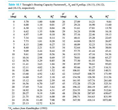
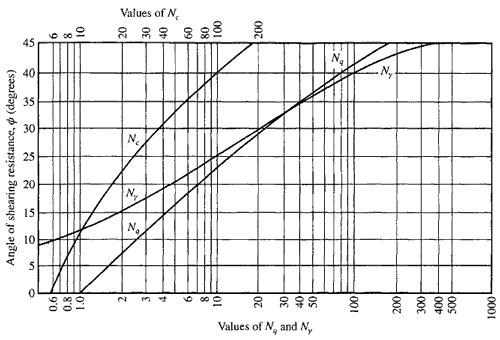
6 6

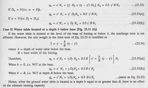

7 Effects of Groundwater Table on Bearing Capacity 7
8 Factor of Safety: Generally, a factor of safety, Fs, of about 3 or more is applied to the ultimate soilbearing capacity to arrive at the value of the allowable bearing capacity. An Fs of 3 or more is not considered too conservative. In nature, soils are neither homogeneous nor isotropic. Much uncertainty is involved in evaluating the basic shear strength parameters of soil. There are two basic definitions of the allowable bearing capacity of shallow foundations. They are gross allowable bearing capacity, and net allowable bearing capacity. The gross allowable bearing capacity can be calculated as As defined by Eq. qall is the allowable load per unit area to which the soil under the foundation should be subjected to avoid any chance of bearing capacity failure. It includes the contribution of (a) the dead and live loads above the ground surface, W(DL ); (b) the self-weight of the foundation, WF; and (c) the weight of the soil located immediately above foundation, WS. Thus, where A area of the foundation. The net allowable bearing capacity is the allowable load per unit area of the foundation in excess of the existing vertical effective stress at the level of the foundation. The vertical effective stress at the foundation level is equal to q gdf. So, the net ultimate load is If we assume that the weight of the soil and the weight of the concrete from which the foundation is made are approximately the same, then 8
9 9
10 10
 that the footing can carry.")

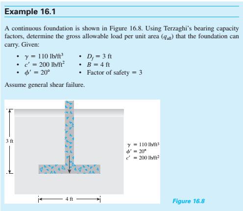
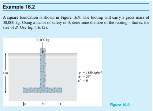
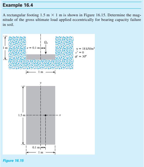
11 Example 16.3 A continuous footing is shown in Figure Using Terzaghi s bearing capacity factors, determine the gross allowable load per unit area (qall) that the footing can carry. Assume general shear failure. Given: γ= 115 lb/ft3, cʹ = 600 lb/ft2, ϕʹ=25, Df = 3.5 ft, B =4 ft, and factor of safety 3. Solution: Example 16.4 A square footing is shown in Figure Determine the gross allowable load, Qall, that the footing can carry. Use Terzaghi s equation for general shear failure (Fs= 3). Given: γ = 105 lb/ft3, γsat = 118 lb/ft3, cʹ=0, ϕʹ= 35, B= 5 ft, Df = 4 ft, and h = 2 ft. 11
12 Solution: Example 16.5 A square footing (B B) must carry a gross allowable load of 42,260 lb. The base of the footing is to be located at a depth of 3 ft below the ground surface. For the soil, we are given that γ= 110 lb/ft3, cʹ= 200 lb/ft 2, and ϕʹ=20. If the required factor of safety is 3, determine the size of the footing. Use Terzaghi s bearing capacity factors and general shear failure of soil. Solution: 12
13 13
14 Ultimate Load for Shallow Foundations Under Eccentric Load 14
15 15
16 16
17 17
18 18
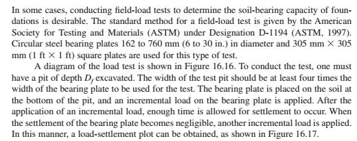
19 Plate-Load Test 19
20 20

21 21
22 Modes of Shear Failure (Summary) General Local Punching Relative Settlement Less Large Large Bulging Significant Less No Tilting of Footing Expected Not expected Not expected Ultimate Load Well defined Not well defined Not well defined Wedge + Wedge + Failure Pattern Slip Surface + Slip Surface + Not well defined Bulging Bulging(no or less) Occurs in (Soil Type) Dense Less compressible Highly Compressible 22
The Bearing Capacity of Soils. Dr Omar Al Hattamleh
 The Bearing Capacity of Soils Dr Omar Al Hattamleh Example of Bearing Capacity Failure Omar Play the move of bearing Capacity failure The Philippine one Transcona Grain Silos Failure - Canada The Bearing
DHANALAKSHMI COLLEGE OF ENGINEERING, CHENNAI DEPARTMENT OF CIVIL ENGINEERING 2 MARK QUESTIONS WITH ANSWERS CE FOUNDATION ENGINEERING UNIT 1
 DHANALAKSHMI COLLEGE OF ENGINEERING, CHENNAI DEPARTMENT OF CIVIL ENGINEERING 2 MARK QUESTIONS WITH ANSWERS CE6502 - FOUNDATION ENGINEERING Subject Code: CE6502 UNIT 1 1. What are the informations obtained
FOUNDATION ENGINEERING UNIT -1 SITE INVESTIGATION & SELECTION OF FOUNDATION 1. What are components of total foundation settlement?
 FOUNDATION ENGINEERING UNIT -1 SITE INVESTIGATION & SELECTION OF FOUNDATION 1. What are components of total foundation settlement? Elastic settlement, consolidation settlement, secondary consolidation
 techie-touch.blogspot.com www.vidyarthiplus.com CE2305 FOUNDATION ENGINEERING 2 MARKS QUESTIONS & ANSWERS 16 MARKS QUESTIONS UNIT -1 1. What are components of total foundation settlement? elastic settlement,
Downloaded from Downloaded from /1
 PURWANCHAL UNIVERSITY VI SEMESTER FINAL EXAMINATION-2003 LEVEL : B. E. (Civil) SUBJECT: BEG359CI, Foundation Engineering. Full Marks: 80 TIME: 03:00 hrs Pass marks: 32 Candidates are required to give their
This document downloaded from vulcanhammer.net vulcanhammer.info Chet Aero Marine
 This document downloaded from vulcanhammer.net vulcanhammer.info Chet Aero Marine Don t forget to visit our companion site http://www.vulcanhammer.org Use subject to the terms and conditions of the respective
CHAPTER 8 BEARING CAPACITY ANALYSES FOR EARTHQUAKES
 CHAPTER 8 BEARING CAPACITY ANALYSES FOR EARTHQUAKES The following notation is used in this chapter: SYMBOL DEFINITION B Width of footing B Reduced footing width to account for eccentricity of load c Cohesion
Chapter 14 Lateral Earth Pressure
 Page 14 1 Chapter 14 Lateral Earth Pressure 1. Which of the following is not a retaining structure? (a) Retaining wall (b) Basement wall (c) Raft (d) Bulkhead 2. When a retaining structure does not move
Foundation Design. π = pi ( radians or 180 ) ρ = reinforcement ratio in concrete beam design = A s /bd µ = coefficient of static friction
 ρ = reinforcement ratio in concrete beam design = A s /bd µ = coefficient of static friction") Foundation Design Notation: a = name for width dimension A = name for area b = width of retaining wall stem at base = width resisting shear stress b o = perimeter length for two-way shear in concrete footing
Foundation Design Notation: a = name for width dimension A = name for area b = width of retaining wall stem at base = width resisting shear stress b o = perimeter length for two-way shear in concrete footing
geopier Lateral resistance
 technical bulletin No. 4 geopier Lateral resistance This Technical Bulletin discusses the behavior of Geopier supported shallow foundation systems when subjected to lateral loads. Lateral loads are applied
An Introduction to Bearing Capacity Analysis
 PDHonline Course C640 (2 PDH) An Introduction to Bearing Capacity Analysis J. Paul Guyer, P.E., R.A., Fellow ASCE, Fellow AEI 2013 PDH Center 5272 Meadow Estates Drive Fairfax, VA 22030-6658 Phone & Fax:
twenty six concrete construction: foundation design ELEMENTS OF ARCHITECTURAL STRUCTURES: FORM, BEHAVIOR, AND DESIGN DR. ANNE NICHOLS SPRING 2013
 ELEMENTS OF ARCHITECTURAL STRUCTURES: FORM, BEHAVIOR, AND DESIGN DR. ANNE NICHOLS SPRING 2013 lecture twenty six concrete construction: www.tamu.edu foundation design Foundations 1 Foundation the engineered
twenty four foundations and retaining walls Foundation Structural vs. Foundation Design Structural vs. Foundation Design
 ALIED ARCHITECTURAL STRUCTURES: STRUCTURAL ANALYSIS AND SYSTEMS DR. ANNE NICHOLS SRING 2018 lecture twenty four Foundation the engineered interface between the earth and the structure it supports that
twenty seven concrete construction: foundation design Foundation Structural vs. Foundation Design Structural vs. Foundation Design
 ARCHITECTURAL STRUCTURES: FORM, BEHAVIOR, AND DESIGN DR. ANNE NICHOLS SRING 2017 lecture twenty seven Foundation the engineered interface between the earth and the structure it supports that transmits
PE Exam Review - Geotechnical
 PE Exam Review - Geotechnical Resources and Visual Aids Item Page I. Glossary... 11 II. Parameters... 9 III. Equations....11 IV. Tables, Charts & Diagrams... 14 1. Module 1 - Soil Classification... 14
An Introduction to Retaining Walls and Excavation Support Systems
 An Introduction to Retaining Walls and Excavation Support Systems J. Paul Guyer, P.E., R.A. Paul Guyer is a registered mechanical engineer, civil engineer, fire protection engineer and architect with over
Brooks/Cole Thomson LearningiM. Fundamentals of Geotechnical Engineering. Braja M. Das. California State University, Sacramento
 Fundamentals of Geotechnical Engineering Braja M. Das California State University, Sacramento Brooks/Cole Thomson LearningiM Australia Canada Mexico Singapore Spain United Kingdom United States CHAPTER
Chapter 13: Retaining Walls
 Chapter 13: Retaining Walls Introduction In general, retaining walls can be divided into two major categories: (a) conventional retaining walls and (b) mechanically stabilized earth walls Conventional
Foundation or Footing Design: Part 1
 Foundation or Footing Design: Part 1 Foundation or Footing Footings are structural elements that transmit column or wall loads to the underlying soil below the structure. Footings are designed to transmit
Types of Foundations
 Shallow Foundations Types of Foundations Foundations can be classified to two major categories: Shallow. Deep. 1 Introduction If the soil stratum is suitable for supporting the structural loads from the
Client Project Job # Wall Loc. SBWall Report deg 120 pcf 950 psf deg 0.0 ft. 6.0 ft 6.0 ft 2.0 ft. W16x50.
 SBWall Report Soils Data Soil Friction Angle, phi Soil Unit Weight, gamma Soil Surcharge (uniform), qs Passive Resistance, FSp Passive Wedge Width, PW*B Backfill Slope Angle, beta Ignore Passive Resistance,
An Introduction To Bearing Capacity Analysis
 An Introduction To Bearing Capacity Analysis J. Paul Guyer, P.E., R.A. Paul Guyer is a registered mechanical engineer, civil engineer, fire protection engineer and architect with over 35 years experience
Compressibility of Soil. Chapter 11
 Compressibility of Soil Chapter 11 TOPICS INTRODUCTION ELASTIC SETTLEMENT Stress distribution in soil masses CONSOLIDATION SETTLEMENT Fundamentals of consolidation Calculation of 1-D Consolidation Settlement
Determination of Bearing Capacity of Circular Footing by a Computer Program Using Meyerhof s Analysis
 Determination of Bearing Capacity of Circular Footing by a Computer Program Using Meyerhof s Analysis Suresh Singh 1, Ankit Maheshwari 1, Kartikaye Joshi 1, Dr..K. Ameta 2 M.E. Scholar, Dept. of Civil
UNIT-1 RETAINING WALLS
 UNIT-1 RETAINING WALLS PART-A 1. Describe about Retaining wall. 2. Define gravity retaining walls. BT-1 3. Classify the types of retaining walls. 4. Explain cantilever retaining wall? 5. Describe about
Footing Bearing Capacity on Elastic-Plastic Soil
 Footing Bearing Capacity on Elastic-Plastic Soil 1 Footing analysis verification Closed-form solutions for the bearing capacity of shallow footings are often used to verify finite element elastic-plastic
Design Illustrations on the Use of Soil Nails to Upgrade Loose Fill Slopes
 Design Illustrations on the Use of Soil Nails to Upgrade Loose Fill Slopes Geotechnical Engineering Office and The Hong Kong Institution of Engineers (Geotechnical Division) November 2013 2 Disclaimer
Bearing Capacity of Geosynthetic Reinforced Foundation Beds on Compressible Clay
 3 r d International Conference on New Developments in Soil Mechanics and Geotechnical Engineering, Bearing Capacity of Geosynthetic Reinforced Foundation Beds on Compressible Clay K. Rajyalakshmi, Lecturer,
b e a r i n g c a p a c i t y o f g e o p i e r - s u p p o r t e d f o u n d a t i o n s y s t e m s
 geopier foundation co inc t e c h n i c a l b u l l e t i n N o. 2 b e a r i n g c a p a c i t y o f g e o p i e r - s u p p o r t e d f o u n d a t i o n s y s t e m s This Technical Bulletin discusses
Settlement Settlements at working loads must not cause damage, nor adversely affect the serviceability of the structure.
 Foundations Load-settlement behaviour Types of foundation Bearing capacity Settlement Foundation design Ground improvement The foundation of a structure is in direct contact with the ground and transmits
Design of Semi gravity Retaining Walls
 Design of Semi gravity Retaining Walls Example 13.1 A semi gravity retaining wall consisting of plain concrete (weight = 145 lb/ft³) is shown in Figure 13.9. The bank of supported earth is assumed to weigh
Combined footings A mat or raft or floating foundation Pile caps
 Foundation or Footing Design: Part 1 Courtesy of Dr. Latifee s IMI research group, Text books (Design of concrete structures by McCormac etc.) and others Foundation or Footing Footings are structural elements
Foundation Engineering
 Foundation Engineering P.C. Varghese Foundation Engineering P.C. VARGHESE Honorary Professor, Anna University, Madras Formerly, Professor and Head, Department of Civil Engineering Indian Institute of Technology
Lecture Retaining Wall Week 12
 Lecture Retaining Wall Week 12 Retaining walls which provide lateral support to earth fill embankment or any other form of material which they retain them in vertical position. These walls are also usually
Behaviour of Raft Foundation with Vertical Skirt Using Plaxis 2d
 International Journal of Engineering Research and Development e-issn: 2278-067X, p-issn: 2278-800X, www.ijerd.com Volume 7, Issue 6 (June 2013), PP. 20-24 ehaviour of Raft Foundation with Vertical Skirt
Seismic bearing capacity factors for strip footings
 Seismic bearing capacity factors for strip footings Amir H.Shafiee 1, M.Jahanandish 2 1- Former MSc Student of Soil Mech. & Found. Eng., Shiraz University, Shiraz, Iran 2- Associate Professor, Civil Eng.
FOUNDATION ENGINEERING UNIT III FOOTINGS AND RAFTS
 1 FOOTINGS AND RAFTS FOUNDATION ENGINEERING UNIT III Types of foundation Contact pressure distribution below footings & raft - Isolated and combined footings types proportioning - mat foundation types
COURSE ON COMPUTATIONAL GEOTECHNICS A Geotechnical Design Tool. Faculty of Civil Engineering UiTM, Malaysia
 COURSE ON COMPUTATIONAL GEOTECHNICS A Geotechnical Design Tool Faculty of Civil Engineering, Malaysia Name : COURSE CONTENTS Use of Plaxis Getting Started Exercise 1: Elastic analysis of drained footing
Advance Design of RC Structure Retaining Wall
 1 Retaining Wall Retaining Walls What are retaining walls Retaining walls are soil-structure systems intended to support earth backfills. Type of retaining walls Gravity retaining wall gravity walls rely
EFFECT OF DEEP EXCAVATION SUPPORTED BY CONCRETE SOLIDER PILE WITH STEEL SHEET PILE LAGGING WALL ON ADJACENT EXISTING BUILDINGS
 EFFECT OF DEEP EXCAVATION SUPPORTED BY CONCRETE SOLIDER PILE WITH STEEL SHEET PILE LAGGING WALL ON ADJACENT EXISTING BUILDINGS Mostafa Abdou 1 *, Ahamed Rushedy Towfeek 2, Waleed Hassan 3 1 prof. Dr.,
Footing Bearing Capacity on Elastic-Plastic Soil
 Footing Bearing Capacity on Elastic-Plastic Soil 1 Footing analysis verification Closed-form solutions for the bearing capacity of shallow footings are often used to verify finite element elastic-plastic
Design of Gravity Flow Pipes 121 = UNIT WT OF SOIL. P d = H H. D = 2r. P x LIVE LOAD PIPE WALLS ARE CLADDING FOR THE SOIL COLUMN SOIL SECTION AA
 Design of Gravity Flow Pipes 11 deflection. Some pipes manufactured in this manner are sometimes referred to as semirigid. This is simply a misnomer. Many solid wall PVC and ductile iron pipes are actually
Typical set up for Plate Load test assembly
 Major disadvantages of field tests are Laborious Time consuming Heavy equipment to be carried to field Short duration behavior Plate Load Test Sand Bags Platform for loading Dial Gauge Testing Plate Foundation
Sabah Shawkat Cabinet of Structural Engineering 2017
 3.9 Concrete Foundations A foundation is a integral part of the structure which transfer the load of the superstructure to the soil without excessive settlement. A foundation is that member which provides
Design Data 6. Loads and Supporting Strengths Elliptical and Arch Pipe. Values of B d
 Design Data 6 Loads and Supporting Strengths Elliptical and Arch Pipe The hydraulic and structural characteristics of elliptical and arch shapes offer advantages, under certain conditions, over the circular
Analysis of Buried Arch Structures; Performance Versus Prediction
 Analysis of Buried Arch Structures; Performance Versus Prediction D.A. Jenkins: Reinforced Earth Pty Ltd, Somersby, NSW, Australia Synopsis: The Reinforced Earth Group introduced the TechSpan arch system
Geotechnical Analysis of Stepped Gravity Walls
 Geotechnical Analysis of Stepped Gravity Walls Baleshwar Singh 1 * and Birjukumar Mistri 2 1 Associate Professor, Civil Engineering Department, IIT Guwahati, India 2 Former Post-Graduate Student, Civil
1. limit equilibrium bearing capacity failure modes
 technical bulletin No. 2 bearing capacity of geopier supported foundation systems This Technical Bulletin discusses the bearing capacity of Geopier supported foundation elements. The behavior of both single
An Introduction to Spread Footings and Mat Foundations
 An Introduction to Spread Footings and Mat Foundations J. Paul Guyer, P.E., R.A. Editor Paul Guyer is a registered civil engineer, mechanical engineer, fire protection engineer, and architect with over
The use of flexible flaps in improving the settlement resistent behaviour of raft foundations
 SECM/15/144 The use of flexible flaps in improving the settlement resistent behaviour of raft foundations J.M.C.J.Jayasundara 1*, B.M.K.L.K.Basnayake 1 and K.G.H.C.N.senaviratne 1 1 University of Peradeniya,
Evaluation on Bearing Capacity of Ring Foundations on two-layered Soil
 Evaluation on Bearing Capacity of Ring Foundations on two-layered Soil R. Ziaie Moayed 1, V. Rashidian 2,and E. Izadi 3 Abstract This paper utilizes a finite element analysis to study the bearing capacity
Chapter 11 Compressibility of Soil
 Page 11 1 Chapter 11 Compressibility of Soil 1. The compression of soil layers as a result of foundation or other loadings is caused by (a) deformation of soil particles. (b) relocation of soil particles.
THE EXPERIMENTAL INVESTIGATION OF FAILURE MECHANISM AND BEARING CAPACITY OF DIFFERENT TYPES OF SHALLOW FOUNDATIONS
 THE EXPERIMENTAL INVESTIGATION OF FAILURE MECHANISM AND BEARING CAPACITY OF DIFFERENT TYPES OF SHALLOW FOUNDATIONS Nissanka Fernando, (Email: nfcharith@yahoo.com) Eranga Sendanayake, (Email: eranga_7@yahoo.com)
Numerical Analysis of the Bearing Capacity of Strip Footing on Reinforced Soil Slope
 Numerical Analysis of the Bearing Capacity of Strip Footing on Reinforced Soil Slope Mohammadreza Hamzehpour Ahmadi 1, Adel Asakereh 2 1 Department of Civil Engineering, University of Hormozgan, Pardis-E-Qeshm
Retaining Wall Design
 SIL 211 MEKANIKA TANAH Retaining Wall Design DR. IR. ERIZAL, MAGR DEPARTEMEN TEKNIK SIPIL DAN LINGKUNGAN FAKULTAS TEKNOLOGI PERTANIAN IPB 1 Conventional Retaining Walls Gravity Retaining Structures Stability
CEX6230 GEOTECHNICS Dear Student:
 CEX6230 GEOTECHNICS 31.05.2010 Dear Student: Geotechnics (CEX6230) discusses design and construction aspects of Geotechnical Engineering. Even though this course requires a pass in CEX4230, I find that
Bearing capacity of foundation on slope
 Balachandra, A., Yang, Z. & Orense, R.P. (2013) Proc. 19 th NZGS Geotechnical Symposium. Ed. CY Chin, Queenstown A Balachandra Sinclair Knights Mertz Pty Ltd., Auckland, NZ (formerly University of Auckland)
BEARING CAPACITY IMPROVEMENT USING MICROPILES A CASE STUDY
 BEARING CAPACITY IMPROVEMENT USING MICROPILES A CASE STUDY G.L. Sivakumar Babu 1, B. R.Srinivasa Murthy 2, D.S. N. Murthy 3, M.S. Nataraj 4 ABSTRACT Micropiles have been used effectively in many applications
Ground Improvement Prof. G.L. Shivakumar Babu Department of Civil Engineering Indian Institute of Science, Bangalore
 Ground Improvement Prof. G.L. Shivakumar Babu Department of Civil Engineering Indian Institute of Science, Bangalore Module No. # 03 Lecture No. # 09 Case Studies in Stone Columns As I just mentioned in
Blade Pile Technical Design Manual 27 June Forward... x
 TABLE OF CONTENTS Forward... x 1 Scope and General... 1 1.1 Scope... 1 1.2 Applications... 1 1.3 Blade Pile Group Capability... 1 1.4 Technical Report Outline... 2 1.5 Notations... 3 2 General Design Requirements...
THE EFFECT OF LATERAL CONFINEMENT ON THE SETTLEMENT CHARACTERISTICS OF SHALLOW FOUNDATIONS ON SAND
 Geotec., Const. Mat. & Env., DOI: https://doi.org/10.21660/2018.51.65933 ISSN: 2186-2982 (Print), 2186-2990 (Online), Japan THE EFFECT OF LATERAL CONFINEMENT ON THE SETTLEMENT CHARACTERISTICS OF SHALLOW
Gambit Centrum Oprogramowania i Szkoleń Sp. z o.o. Mathcad 14 Roark's Formulas for Stress and Strain
 Mathcad 14 Roark's Formulas for Stress and Strain Table of Contents About Mathcad E-Books Notes on the Organization and Special Features of Roark's Formulas for Stress and Strain Preface by Warren C. Young
Finite Element Analysis of Flexible Anchored Sheet Pile Walls: Effect of Mode of Construction and Dewatering Naveen Kumar 1, Arindam Dey 2*
 Golden Jubilee Conference of the IGS Bangalore Chapter, Geo-Innovations, 30-31 October 2014 Finite Element Analysis of Flexible Anchored Sheet Pile Walls: Effect of Mode of Construction and Dewatering
4.6 Procedures for Connections
 4.6 Procedures for Connections This section provides Tier 2 evaluation procedures that apply to structural connections: anchorage for normal forces, shear transfer, vertical components, interconnection
System Assemblies & Load Tracing
 System Assemblies & Load Tracing Notation: a = name for a dimension C = symbol for compression DL = shorthand for dead load F horizontal-resisting = total force resisting horizontal sliding F sliding =
Cantilever or Restrained Retaining Wall Calculations
 Cantilever or Restrained Retaining Wall Calculations Organization: F.E.C. Project Name: Example Report Design by: LAA Job #: 9876 Date: 10/21/2013 Codes used: 2010 & 2013 CBC, 2009 & 2012 IBC, ACI 318-08
NUMERICAL EVALUATION OF BEARING CAPACITY OF SHALLOW FOUNDATION RESTING ON SANDY SOIL BASED ON SHEAR CRITERIA AND SETTLEMENT CRITERIA
 Int. J. of Intelligent Computing and Applied Sciences 3 NUMERICAL EVALUATION OF BEARING CAPACITY OF SHALLOW FOUNDATION RESTING ON SANDY SOIL BASED ON SHEAR CRITERIA AND SETTLEMENT CRITERIA Sourya Snigdha
Rewa Engineering College, Rewa. Rewa
 Rewa Engineering College, Rewa Rewa 486001 Department OF Civil Engineering VIII TH SEMESTER GEOTECHNICAL ENGG II SESSION: 2017-18 Prepared by: Anoop Kumar Tiwari Approved by (HOD) 1 OBJECTIVES Design of
Geosynthetics and Reinforced Soil Structures Prof. K. Rajagopal Department of Civil Engineering Indian Institute of Technology, Madras
 Geosynthetics and Reinforced Soil Structures Prof. K. Rajagopal Department of Civil Engineering Indian Institute of Technology, Madras Lecture - 21 Geosynthetic Reinforced Soil Embankments I Good morning
ARCH 331. Study Guide for Final Examination
 ARCH 331. Study Guide for Final Examination This guide is not providing answers for the conceptual questions. It is a list of topical concepts and their application you should be familiar with. It is an
Building Construction
 Building Construction Shallow Foundations Module-III Introduction The foundation can be classified broadly into two types: Shallow foundations Deep foundations Shallow foundations Shallow Foundations When
Effect of Cavities on the Behaviour of Strip Footing Subjected to Inclined Load
 Effect of Cavities on the Behaviour of Strip Footing Subjected to Inclined Load Ali A. Al-Jazaairry, Tahsin T. Sabbagh Abstract One of the important concerns within the field of geotechnical engineering
Stability of a Mechanically Stabilized Earth Wall
 Stability of a Mechanically Stabilized Earth Wall GEO-SLOPE International Ltd. www.geo-slope.com 1400, 633-6th Ave SW, Calgary, AB, Canada T2P 2Y5 Main: +1 403 269 2002 Fax: +1 403 266 4851 Introduction
DESIGN AND DETAILING OF RETAINING WALLS
 DESIGN AND DETAILING OF RETAINING WALLS (For class held from nd April 07) Dr. M. C. Nataraja, Professor, Civil Engineering Department, Sri Jayachamarajendra Collge of Engineering, Mysore-5a70 006 Phone:
Principles of STRUCTURAL DESIGN. Wood, Steel, and Concrete SECOND EDITION RAM S. GUPTA. CRC Press. Taylor& Francis Group
 SECOND EDITION Principles of STRUCTURAL DESIGN Wood, Steel, and Concrete RAM S. GUPTA CRC Press Taylor& Francis Group Boca Raton London New York CRC Press is an imprint of the Taylor & Francis Croup, an
GEOTECHNICAL RESISTANCE FACTORS
 Chapter 9 GEOTECHNICAL RESISTANCE FACTORS Final SCDOT GEOTECHNICAL DESIGN MANUAL 9-i Table of Contents Section Page 9.1 Introduction... 9-1 9.2 Soil Properties... 9-2 9.3 Resistance Factors for LRFD Geotechnical
Foundations. Foundations form the major part of a buildings substructure (along with the rising walls, hardcore and ground floors)
") Foundations Foundations form the major part of a buildings substructure (along with the rising walls, hardcore and ground floors) Once the substructure is complete the building is out of the ground and
Foundations Foundations form the major part of a buildings substructure (along with the rising walls, hardcore and ground floors) Once the substructure is complete the building is out of the ground and
DESIGN OF RETAINING WALLS
 DESIGN OF RETAINING WALLS Dr. Izni Syahrizal bin Ibrahim Faculty of Civil Engineering Universiti Teknologi Malaysia Email: iznisyahrizal@utm.my Introduction Retaining wall is used to retain earth or other
Research Paper PERFORMANCE OF STRIP FOOTING ON SANDY SOIL DUE TO TUNNELING S.Hariswaran 1, K.Premalatha 2, K.Raja 3
 Research Paper PERFORMANCE OF STRIP FOOTING ON SANDY SOIL DUE TO TUNNELING S.Hariswaran 1, K.Premalatha 2, K.Raja 3 Address for Correspondence 1 Assistant Professor, Department of Civil Engineering, Agni
Cantilever or Restrained Retaining Wall Design Calculations
 Cantilever or Restrained Retaining Wall Design Calculations Organization: F.E.C. Project Name: Ex 3 Driveway Short Wall Design by: LAA Job #: Date: 7/5/2016 Codes used: 2012 + 2015 IBC, ACI 318-14, ACI
DESIGNING AND CONSTRUCTION OF T-WALL RETAINING WALL SYSTEM
 Istanbul Bridge Conference August 11-13, 2014 Istanbul, Turkey DESIGNING AND CONSTRUCTION OF T-WALL RETAINING WALL SYSTEM T. C. NEEL and K.BOZKURT ABSTRACT This work shall consist of the design, manufacture
5. Report Date May Work Unit No.
 1. Report No. FHWA/LA.08/44 4. Title and Subtitle Use of Reinforced Soil Foundation (RSF) to Support Shallow Foundation 7. Author(s) Murad Y. Abu-Farsakh, Ph.D., P.E., and Qiming Chen, Ph.D. 9. Performing
PARAMETRIC STUDY OF SHALLOW FOUNDATION BEARING CAPACITY IN CLAYEY SOIL
 International Journal of Civil Engineering and Technology (IJCIET) Volume 9, Issue 10, October 2018, pp. 1223 1230, Article ID: IJCIET_09_10_121 Available online at http://www.iaeme.com/ijciet/issues.asp?jtype=ijciet&vtype=9&itype=10
BEHAVIOUR OF ECCENTRICALLY LOADED CIRCULAR FOOTING ON GRANULAR SOIL MASTER OF TECHNOLOGY IN (GEOTECHNICAL ENGINEERING) SUBMITTED BY SARITA JENA
 SUBMITTED BY SARITA JENA") BEHAVIOUR OF ECCENTRICALLY LOADED CIRCULAR FOOTING ON GRANULAR SOIL RESEARCH PROJECT SUBMITTED IN PARTIAL FULFILLMENT OF REQUIREDMENTS FOR THE DEGREE OF MASTER OF TECHNOLOGY IN (GEOTECHNICAL ENGINEERING)
BEHAVIOUR OF ECCENTRICALLY LOADED CIRCULAR FOOTING ON GRANULAR SOIL RESEARCH PROJECT SUBMITTED IN PARTIAL FULFILLMENT OF REQUIREDMENTS FOR THE DEGREE OF MASTER OF TECHNOLOGY IN (GEOTECHNICAL ENGINEERING)
mortarless masonry Design Manual Part 1 (IS 456:2000) Section 1 Page 1 IS 456:2000 PLAIN AND REINFORCED CONCRETE - CODE OF PRACTICE
 Section 1 Page 1 IS 456:2000 PLAIN AND REINFORCED CONCRETE - CODE OF PRACTICE") SECTION 1. mortarless masonry Design Manual Part 1 (IS 456:2000) Section 1 Page 1 1.1 Overview of IS 456:2000 IS 456:2000 PLAIN AND REINFORCED CONCRETE - CODE OF PRACTICE IS 456:2000 is the current Indian
SECTION 1. mortarless masonry Design Manual Part 1 (IS 456:2000) Section 1 Page 1 1.1 Overview of IS 456:2000 IS 456:2000 PLAIN AND REINFORCED CONCRETE - CODE OF PRACTICE IS 456:2000 is the current Indian
CHAPTER 10: GENERAL STRUCTURAL DETAILS
 CHAPTER 10: GENERAL STRUCTURAL DETAILS 10.1 GENERAL It shall be in accordance with JSCE Standard Specification (Design), 9.1, "steel" shall be taken to signify "steel or CFRM". 10.2 CONCRETE COVER (1)
Misan University - College of Engineering Civil Engineering Department
 CHAPTER 2 Soil and Excavations Soil investigation including two phases: surface investigation and subsurface investigation Surface investigation involves making a preliminary judgment about the site s
CHAPTER 2. Design Formulae for Bending
 CHAPTER 2 Design Formulae for Bending Learning Objectives Appreciate the stress-strain properties of concrete and steel for R.C. design Appreciate the derivation of the design formulae for bending Apply
Integral Bridges and the. Modeling of Soil-Structure Interaction
 Integral Bridges and the Click to edit Master title style Modeling of Soil-Structure Interaction Julian Moses, Principal Engineer, LUSAS Introduction 2 Introduction 3 Introduction 4 About soil-structure
APPROXIMATE ANALYSIS OF PILED RAFT. Rameez Gahlot1, Roshni J John2
 APPROXIMATE ANALYSIS OF PILED RAFT Rameez Gahlot1, Roshni J John2 1 PG Student, Dept of Civil Engg, Saraswati College of Engineering, Kharghar-4121, India rameezgahlot@gmail.com.2 Head of Civil Engineering
Optimization of Reinforced Concrete Retaining Walls of Varying Heights using Relieving Platforms
 Optimization of Reinforced Concrete Walls of Varying Heights using Relieving Platforms Prof. Sarita Singla Civil Engineering Department PEC University of Technology Chandigarh, India Er. Sakshi Gupta M.E.
Strip Footing - Ultimate Bearing Capacity
 Strip Footing - Ultimate Bearing Capacity analys: nonlin phase physic. constr: suppor tying. elemen: ct12e pstrai. load: deform weight. materi: consta crack cutoff elasti full harden isotro mohrco multil
Analysis of T-Shape Footing On Layered Sandy Soil
 ISSN(Online) : 9-875 ISSN (Print) : 7-67 (An ISO 97: 7 Certified Organization) Vol. 6, Issue 6, June 7 Analysis of T-Shape Footing On Layered Sandy Soil Gargi V. Kulkarni, Prof. S. W. Thakare P.G. Student,
SETTLEMENTS DUE TO TUNNEL CONSTRUCTION
 5 SETTLEMENTS DUE TO TUNNEL CONSTRUCTION In this tutorial the construction of a shield tunnel in medium soft soil and the influence on a pile foundation is considered. A shield tunnel is constructed by
GATE SOLVED PAPER - CE
 YEAR 2013 ONE MARK Q. 1 In its natural condition a soil sample has a mass of 1. 980 kg and a volume of 0. 001 m 3. After being completely dried in an oven; the mass of the sample is 1. 800 kg. Specific
Application Note - Cantilever Stem Wall Analysis
 LS-G-AN4 Software: LimitState:GEO 2.0f Date: February 2011 Application Note - Cantilever Stem Wall Analysis 1 Introduction This note describes the typical steps followed in setting up and analysing a cantilever
(Refer Slide Time: 04:08)
") Soil Mechanics Prof. B.V.S. Viswanathan Department of Civil Engineering Indian Institute of Technology, Bombay Lecture 27 Flow of water through soils-viii Welcome to lecture number eight of flow of water
Soil Mechanics Prof. B.V.S. Viswanathan Department of Civil Engineering Indian Institute of Technology, Bombay Lecture 27 Flow of water through soils-viii Welcome to lecture number eight of flow of water
Evaluation of negative skin friction on sheet pile walls at the Rio Grande dry dock, Brazil
 Geotechnical Aspects of Underground Construction in Soft Ground Viggiani (ed) 2012 Taylor & Francis Group, London, ISBN 978-0-415-68367-8 Evaluation of negative skin friction on sheet pile walls at the
Design of a non-anchored retaining wall
 Engineering manual No. 4 Updated: 03/2018 Design of a non-anchored retaining wall Program: Sheeting design File: Demo_manual_04.gp1 This engineering manual describes the design of a non-anchored retaining
10-COLUMNS: 10.1 Introduction.
 1 10-COLUMNS: 10.1 Introduction. Columns are vertical compression members of a structural frame intended to support the loadcarrying beams. They transmit loads from the upper floors to the lower levels