Grade separated interchange at the intersection of U.S. Hwy 17 Bypass and Farrow Parkway
|
|
|
- Barry Wilkins
- 6 years ago
- Views:
Transcription
1 Grade separated interchange at the intersection of U.S. Hwy 17 Bypass and Farrow Parkway Jeff Sizemore, P.E. Geotechnical Design Support Engineer SCDOT Ed Tavera, P.E. Principal Geotechnical Engineer Geoengineers
2 Need for Project: The purpose of the project is to improve traffic flow, increase intersection capacity, and improve safety within the intersection and along US 17. The US 17 and SC 707/ Farrow Parkway intersection is currently experiencing substantial congestion during peak morning and afternoon travel periods.


3 Project Site Enlarged Map Zone Project Site
4 Existing US 17 Bypass US17 BP East

5 Proposed US17 Bypass US 17 BP
6 Project Layout Ramp C Backgate Bridge Ramp D Ramp A End Bent 1 End Bent 7 Ramp B South Bridge Approach North Bridge Approach

7 South Subsurface Profile

8 North Subsurface Profile
9 Project Design Constraints Project Geometry and Layout Project Constructed on Existing Alignment Complex Traffic Control Staging Plan (Geotechnical Designs Constructed in Stages 2, 3, and 4) Total Project Construction Time Requirements Approx. 3.5 years High Traffic Volume Combined with Limited Construction Staging Areas
10 Geotechnical Key Issues Consolidation Settlement Seismic Slope Stability (Liquefaction) Bridge Abutment Foundation Performance Extreme Event I and II
11 Settlement At Bridge Abutments (Normal Weight Fill)

12 Longitudinal Seismic Slope Instability

13 Transverse Seismic Slope Instability
")
14 Stiff Clay (Pee Dee Formation) 66 - HP14X117 X 100 ft long Bridge Abutment Unimproved Foundation Performance Axial Load Bridge Lateral Load Extreme Event II Extreme Event I Excessive Sand Medium Clay 40 feet 90 feet Row End Bent 7 (North Abutment)
15 Ground Improvement Methods Lightweight Aggregate Borrow Material Reduce Magnitude of Settlement Prefabricated Vertical Drain (PVD) / Granular Surcharges Increased Rate of Settlement during Construction Deep Soil Mixing Seismic Slope Stability and Bridge Abutment Foundation Improved Performance Mechanically Stabilized Earth (MSE) Walls Permanent and Temporary Retaining Walls
 Required")

 MSE Wall Reinforced")
16 Lightweight Aggregate (Rotary Kilin Produced) Required Properties: Internal Friction Angle 40 degrees Unit Weight: 60 pcf minimum (Long-term 70 pcf maximum) MSE Wall Reinforced Backfill Properties
17 Settlement South Bridge Abutment (End Bent 1)
18 Settlement North Bridge Abutment (End Bent 7)
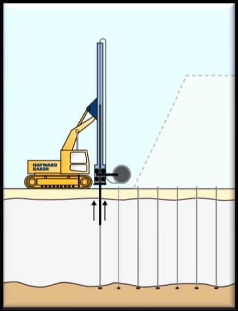
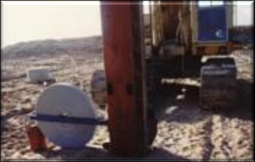
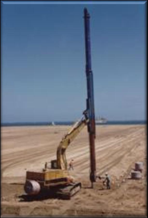
19 Prefabricated Vertical Drains (PVD)
20 PVD Installation S PVD PVD Triangular Installation Pattern PVD 2 Drainage Sand Layer Geotextile Separator Fabric
21 Granular Surcharges Required Properties: Internal Friction Angle 32 degrees Unit Weight: 120 pcf Granular Surcharge Lightweight Aggregate Borrow Material

22 Seismic Slope Stability Improved Deep Soil Mixing

23 Stage 4 Ground Improvement North/South Abutment (Typical)


24 Deep Soil Mixing Lime-Cement Columns Block Type Pattern - Overlapping (Dry Mix Method) Seismic Slope Stabilization Shear Key Improved Performance of Bridge Abutment Foundations
25 10 Feet Min. DSM-LCC Test Sections 10 Feet Min. 1 2 Test Pile 1 (HP 14x117) 4 3 Test LCC No DSM-LCC Test Section 1 (Block Type Pattern) Test LCC Sampling Quadrants DSM-LCC Test Section 2 (Single Line Pattern) Legend Test Lime-Cement Columns (Test LCC)
26 Bridge Abutment Improved Foundation Performance End Bent 7 (North Abutment) Extreme Event I < ¼ End Bent 7 (North Abutment) Extreme Event II (Case 3) < 1/8
27 Geotechnical Instrumentation Settlement Monitoring 12 VW Settlement Sensors (SS) 15 VW Piezometers (P) 2 VW Data Collection Centers 10 Settlement Plates (SP) 2 Magnetic Extensometer (ME) Slope Stability 6 Slope Indicator
28 Traffic Control Stage 2 Ramp A Ramp B
 3 and 4 Triangular Spacing PVD Geotechnical")
29 Traffic Stage 2 Ground Improvement Ramp A Ramp B MSE Walls Lightweight Aggregate Borrow Material 2, and 3 Granular Surcharge (Normal Weight) 3 and 4 Triangular Spacing PVD Geotechnical Instrumentation
30 Traffic Control Stage 3 Ramp C Ramp D
 3 and 4 Triangular Spacing PVD Geotechnical")
31 Traffic Stage 3 -Ground Improvement Ramp B Ramp C MSE Walls Lightweight Aggregate Borrow Material 1, 2, and 4 Granular Surcharge (Normal Weight) 3 and 4 Triangular Spacing PVD Geotechnical Instrumentation

32 Traffic Control Stage 4 Backgate Bridge South Bridge Approach North Bridge Approach
 Longitudinal DSM-LCC (South 5 Wide / North 8 Wide)")
33 Traffic Stage 4 -Ground Improvement South Bridge Approach Bridge South Bridge Approach MSE Walls Lightweight Aggregate Borrow Material 1, 2, and 3 Granular Surcharge (Normal Weight) 3 Triangular Spacing PVD Geotechnical Instrumentation Bridge Abutment DSM-LCC (South 30 x 133 x 50 deep North 30 x 141 x 70 deep ) Longitudinal DSM-LCC (South 5 Wide / North 8 Wide)

34 X- Section End Bent 7 (250+26)

35 X- Section End Bent 7 (252+00)
36 Initial MSE Wall Construction (2 & 3 Stage Wall Construction) Drainage Pipe Flexible Wire Facing B Req MSE Wall Soil Reinforcement Light Weight Aggregate Geotextile Separator Fabric
37 2-Stage MSE Wall Construction (Stage 1 of 2) Sand Surcharge Sand Surcharge Flexible Wire Facing Light Weight Aggregate Borrow Material
38 Permanent Precast Concrete Segmental Panel Flexible Wire Facing Fill Void w/light Weight Fill Precast Concrete Segmental Panel Lightweight Aggregate Precast Concrete Panel Connector 1 Minimum 2 Maximum
39 Permanent Full Height Concrete Panel (Pre-Cast or Cast-In-Place) Fill Void w/lightweight Aggregate Deadman Anchor Flexible Wire Facing Precast or Cast-In-Place Full Height Concrete Panel Facing Lightweight Aggregate 6 Maximum Void


40 MSE Walls Permanent MSE Walls Two-Stage Construction Three-Stage Construction (w/drainage Structures) Temporary MSE Walls (Welded Wire Mesh Facing)
41 3-Stage MSE Wall Construction With Drainage Structure (Stage 1 of 3) Flexible Wire Facing Sand Surcharge Sand Surcharge Drainage Structure Blockout Area Light Weight Fill
42 3-Stage MSE Wall Construction With Drainage Pipe (Stage 2 of 3) Flexible Wire Facing Drainage Pipe Lightweight Aggregate
43 3-Stage MSE Wall Construction With Drainage Structure (Stage 2 of 3) Flexible Wire Facing Structural Frame Lightweight Aggregate
44 3-Stage MSE Wall Construction With Drainage Structure (Stage 2 of 3) Flexible Wire Facing Light Weight Fill
45 Lightweight Aggregate Borrow Material 4 Feet Long Biaxial Geogrids Placed on 2 Feet Vertical Spacing 2 Feet Thick Cover of Borrow Silty or Clayey Soil Materials Minimum 2 Feet Drainage Layer
46 Project Construction Phase (North Abutment Sta ) Ramp D Stage 3 Bridge Approach Embankment Stage 4 Ramp B Stage 2
47 Bridge Abutment Construction (North Abutment End Bent 7)
48 US 17- Bypass Over SC707/Farrow Parkway (Backgate Bridge) Myrtle Beach, SC Horry County Thank You Any Questions?
Louisiana Transportation Conference February 17-20, 2013
 Case Study: Rapid Embankment Construction of US 17 Bypass Interchange Over Soft Compressible Soils Using Lightweight Aggregate Myrtle Beach, South Carolina Presented By: Ed Tavera, PE Louisiana Transportation
Long-Term Settlement Performance Monitoring, I-15 Reconstruction Project, Salt Lake City, UT. Steven Bartlett, University of Utah
 1 Long-Term Settlement Performance Monitoring, I-15 Reconstruction Project, Salt Lake City, UT Steven Bartlett, University of Utah Roadway Widening (I-15 Project) Salt Lake City Utah, USA 2002 Host of
Performance of Mechanically Stabilized Earth walls over compressible soils
 Performance of Mechanically Stabilized Earth walls over compressible soils R.A. Bloomfield, A.F. Soliman and A. Abraham The Reinforced Earth Company, Vienna, Virginia, USA ABSTRACT: Two projects have recently
CHAPTER 11: WALLS.
 CHAPTER 11: WALLS MODULAR BLOCK WALL (DRY CAST) Rather than being pre-approved as systems, the components of Modular block walls (dry cast) are pre-approved separately. The approved MBW components are
MECHANICALLY STABILIZED EARTH (MSE) WALL SYSTEMS
 WALL SYSTEMS") DRAINAGE SOLUTIONS SINCE 1908 MECHANICALLY STABILIZED EARTH (MSE) WALL SYSTEMS PERMANENT AND TEMPORARY ENGINEERED WALL SOLUTIONS ECONOMICAL DURABLE VERSATILE ARMTEC.COM MSE RETAINING WALLS Armtec Mechanically
DRAINAGE SOLUTIONS SINCE 1908 MECHANICALLY STABILIZED EARTH (MSE) WALL SYSTEMS PERMANENT AND TEMPORARY ENGINEERED WALL SOLUTIONS ECONOMICAL DURABLE VERSATILE ARMTEC.COM MSE RETAINING WALLS Armtec Mechanically
FLORIDA DEPARTMENT OF TRANSPORTATION
 TEMPORARY WIREWALL MSE RETAINING WALLS SAMPLE DETAIL DRAWINGS INDEX DESCRIPTION 1 TITLE 2 GENERAL NOTES 3-4 TEMPORARY WIREWALL DETAILS 5-6 TRI-WEB TEMPORARY WALL DETAILS 7 TYPICAL TEMPORARY WIREWALL 8
Best Practices for Design and Construction of MSE Walls
 Best Practices for Design and Construction Robert A. Gladstone, P.E. Executive Director Association for Mechanically Stabilized Earth Geotechnical Consultant Workshop Ohio Department of Transportation
ODOT Design & Construction Requirements for MSE Walls
 ODOT Design & Construction Requirements for MSE Walls Peter Narsavage, P.E. Foundation Engineering Coordinator Ohio Department of Transportation Office of Structural Engineering 2006 Ohio Transportation
JOB BB0414 PORTER RD. HWY. 112/71B WIDENING & INTCHNG. IMPVTS. (S) AUGUST 10, 2016
 AUGUST 10, 2016") JOB BB0414 PORTER RD. HWY. 112/71B WIDENING & INTCHNG. IMPVTS. (S) AUGUST 10, 2016 Is it allowable to substitute the WF beams to Plate Girders on Bridge 05692? The substitution of a plate girder with flanges
JOB BB0414 PORTER RD. HWY. 112/71B WIDENING & INTCHNG. IMPVTS. (S) AUGUST 10, 2016 Is it allowable to substitute the WF beams to Plate Girders on Bridge 05692? The substitution of a plate girder with flanges
or (800)
") WWW.CELL-CRETE.COM or (800) 669-0433 CALIFORNIA (Lic #243404), OREGON, WASHINGTON, NEVADA, UTAH, IDAHO, MONTANA, ARIZONA, HAWAII, ALASKA, WESTERN CANADA Re: Cellular Concrete as Engineered Fill I m pleased
WWW.CELL-CRETE.COM or (800) 669-0433 CALIFORNIA (Lic #243404), OREGON, WASHINGTON, NEVADA, UTAH, IDAHO, MONTANA, ARIZONA, HAWAII, ALASKA, WESTERN CANADA Re: Cellular Concrete as Engineered Fill I m pleased
GEOSYNTHETICS ENGINEERING: IN THEORY AND PRACTICE
 GEOSYNTHETICS ENGINEERING: IN THEORY AND PRACTICE Prof. J. N. Mandal Department of Civil Engineering, IIT Bombay, Powai, Mumbai 400076, India. Tel.022-25767328 email: cejnm@civil.iitb.ac.in Module - 6
Construction and Long Term Performance of Transportation Infrastructure Constructed Using EPS Geofoam on Soft Soil Sites in Salt Lake Valley, Utah
 Construction and Long Term Performance of Transportation Infrastructure Constructed Using EPS Geofoam on Soft Soil Sites in Salt Lake Valley, Utah Bartlett, Steven 1, Negussey, Dawit 2, Farnsworth, Clifton
PROPOSED SEGMENTAL RETAINING WALLS ARGONAUT RETAIL VILLAGE - PHASE I PENSACOLA, FLORIDA
 CERTIFICATE AUTHORIZATION: 2 24 ANCHOR WALL ENGINEERING, LLC MATERIAL NOTES. Concrete Retaining Wall Units: "Anchor Diamond Pro Retaining Wall Units" as manufactured by Block USA under license from Anchor
MagnumStone Specifications Gravity
 MagnumStone Specifications Gravity SPECIFICATION FOR MAGNUMSTONE GRAVITY MECHANICALLY STABILIZED EARTH SYSTEM PART 1: GENERAL.01Description The work consists of supplying and installing all aspects of
SPECIFICATIONS FOR PRECAST MODULAR BLOCK RETAINING WALL SYSTEM (revised 5/8/7)
") Page 1 of 7 STONE STRONG SYSTEMS SPECIFICATIONS FOR PRECAST MODULAR BLOCK RETAINING WALL SYSTEM (revised 5/8/7) PART 1: GENERAL 1.01 Description A. Work includes furnishing and installing precast modular
Page 1 of 7 STONE STRONG SYSTEMS SPECIFICATIONS FOR PRECAST MODULAR BLOCK RETAINING WALL SYSTEM (revised 5/8/7) PART 1: GENERAL 1.01 Description A. Work includes furnishing and installing precast modular
Earth Retaining System
 Hashemite University Department of Civil Engineering Foundation Engineering Dr. Omar Al-Hattamleh Earth Retaining System Earth slopes and earth retaining structures Used to maintain two different ground
SCG INTERNATIONAL TRINIDAD AND TOBAGO LIMITED COUVA CHILDREN S HOSPITAL
 SCG INTERNATIONAL TRINIDAD AND TOBAGO LIMITED COUVA CHILDREN S HOSPITAL GEOTECHNICAL CONSULTANT Prepared by Checked by Approved by Mr. C Allen Dr. Derek Gay Dr. Derek Gay Signature Date Signature Date
Notes for Erection of Evergreen Maxi Wall Retaining Walls
 Notes for Erection of Evergreen Maxi Wall Retaining Walls 1. Evergreen Maxi General Notes A. Project drawings - See project drawings for complete layout of utilities, railroad tracks, existing and proposed
SPECIFICATIONS FOR PRECAST MODULAR BLOCK RETAINING WALL SYSTEM (revised 9/17/18)
") Page 1 of 8 STONE STRONG SYSTEMS SPECIFICATIONS FOR PRECAST MODULAR BLOCK RETAINING WALL SYSTEM (revised ) PART 1: GENERAL 1.01 Description A. Work includes furnishing and installing precast modular blocks
Page 1 of 8 STONE STRONG SYSTEMS SPECIFICATIONS FOR PRECAST MODULAR BLOCK RETAINING WALL SYSTEM (revised ) PART 1: GENERAL 1.01 Description A. Work includes furnishing and installing precast modular blocks
MSE WALLS CASE STUDIES. by John G. Delphia, P.E. TxDOT Bridge Division Geotechnical Branch
 MSE WALLS CASE STUDIES by John G. Delphia, P.E. TxDOT Bridge Division Geotechnical Branch COMMON RETAINING WALL TYPES CONCRETE BLOCK MSE TEMPORARY EARTH SPREAD FOOTING Gabions Drilled Shaft Soil Nail Tiedback
Behavior of Reinforced Embankment on Soft Ground with and without Jet Grouted Soil-Cement Piles
 Behavior of Reinforced Embankment on Soft Ground with and without Jet Grouted Soil-Cement Piles by 1 Dennes T. Bergado and 2 Glen A. Lorenzo 1 Professor and 2 Doctoral Candidate, respectively Geotechnical
MECHANICALLY STABILIZED EARTH (MSE) WALLS
 WALLS") Supplemental Technical Specification for MECHANICALLY STABILIZED EARTH (MSE) WALLS SCDOT Designation: SC-M-713 (01/19) 1.0 RELEVANCE 1.1 This Supplemental Technical Specification (STS) replaces Section
Supplemental Technical Specification for MECHANICALLY STABILIZED EARTH (MSE) WALLS SCDOT Designation: SC-M-713 (01/19) 1.0 RELEVANCE 1.1 This Supplemental Technical Specification (STS) replaces Section
DESIGNING AND CONSTRUCTION OF T-WALL RETAINING WALL SYSTEM
 Istanbul Bridge Conference August 11-13, 2014 Istanbul, Turkey DESIGNING AND CONSTRUCTION OF T-WALL RETAINING WALL SYSTEM T. C. NEEL and K.BOZKURT ABSTRACT This work shall consist of the design, manufacture
C-R-S: PID: Reviewer: Date:
 C-R-S: PID: Reviewer: Date: Settlement 1 If soil conditions and project requirements warrant, have settlement issues been addressed? If not applicable (X), go to Question 14 2 Have consolidation properties
ENGINEERING DIRECTIVE
 Number: E-95-001 Date: 2/2/95 ENGINEERING DIRECTIVE Ross B. Dindio (Signature on Original) CHIEF ENGINEER The purpose of this engineering directive is to formally notify ALL Department engineering personnel
Chapter 18 EARTH RETAINING STRUCTURES
 Chapter 18 EARTH RETAINING STRUCTURES Final SCDOT GEOTECHNICAL DESIGN MANUAL June 2010 SCDOT Geotechnical Design Manual Earth Retaining Structures Table of Contents Section Page 18.1 Introduction...18-1
Save time. Save money. Specify a fast, economical Vist-A-Wall MSE. fast and easy to install. They adapt well to curves, angles and
 bigrbridge.com Save time. Save money. Specify a fast, economical Vist-A-Wall MSE Structural Wall System for your next engineered embankment project. These historically-proven, cost-effective systems have
STATE OF OHIO DEPARTMENT OF TRANSPORTATION SUPPLEMENTAL SPECIFICATION 867 TEMPORARY WIRE FACED MECHANICALLY STABILIZED EARTH WALL.
 STATE OF OHIO DEPARTMENT OF TRANSPORTATION SUPPLEMENTAL SPECIFICATION 867 TEMPORARY WIRE FACED MECHANICALLY STABILIZED EARTH WALL April 15, 2016 867.01 Description 867.02 Definitions 867.03 Materials 867.04
FOUNDATIONS. Foundations Copyright G G Schierle, 2006 Press Esc to end, for next, for previous slide 1
 FOUNDATIONS Foundations Copyright G G Schierle, 2006 Press Esc to end, for next, for previous slide 1 Liquefaction reduced the soil strength under these apartment buildings in Niigata (Japan) 1964. Liquefaction
MOA Project # Golden View Drive Intersection & Safety Upgrades
 Appropriate transitions can include extending the insulation beyond the roadway improvements, reducing the insulation thickness, or angling the insulation downward. Use of a frost tolerant section, an
Geotechnical Solutions for High Speed Track Embankment A Brief Overview
 Geotechnical Solutions for High Speed Track Embankment A Brief Overview Ir. Dr. Gue See Sew Managing Director, Gue & Partners Sdn Bhd & Ir. Tan Yean Chin Associate Director, Gue & Partners Sdn Bhd ABSTRACT:
DECEMBER 5, 2017 AT 2:00 P.M. (EASTERN TIME) (Estimated Cost: $5,000,000) Bids
 (Estimated Cost: $5,000,000) Bids") General Info Number: PROJECT NO. 43-17-04 : BRIDGE DECK REPAIR AND BRIDGE REMOVAL OHIO TURNPIKE OVER QUARRY ROAD, M.P. 138.0 OHIO TURNPIKE OVER INACTIVE RAILROAD, M.P. 138.2 LORAIN COUNTY, OHIO Deadline:
General Info Number: PROJECT NO. 43-17-04 : BRIDGE DECK REPAIR AND BRIDGE REMOVAL OHIO TURNPIKE OVER QUARRY ROAD, M.P. 138.0 OHIO TURNPIKE OVER INACTIVE RAILROAD, M.P. 138.2 LORAIN COUNTY, OHIO Deadline:
SEISMIC SOIL-STRUCTURE INTERACTION IN FULLY INTEGRAL ABUTMENT BRIDGES WITH HP STEEL PILES
 SEISMIC SOIL-STRUCTURE INTERACTION IN FULLY INTEGRAL ABUTMENT BRIDGES WITH HP STEEL PILES YU BAO 1 and ANDREW RIETZ 2 1 : Assistant Professor, Department of Civil Engineering Technology, Environmental
INSPECTION GUIDE FOR SEGMENTAL RETAINING WALLS TEK 18-11B
 An information series from the national authority on concrete masonry technology INSPECTION GUIDE FOR SEGMENTAL RETAINING WALLS TEK 18-11B Quality Assurance and Testing (2012) INTRODUCTION Segmental retaining
GEOTECHNICAL INVESTIGATION I-15 MILE POST CL 120 INTERCHANGE MESQUITE, NEVADA PREPARED FOR:
 GEOTECHNICAL INVESTIGATION I-15 MILE POST CL 120 INTERCHANGE MESQUITE, NEVADA PREPARED FOR: HORROCKS ENGINEERS 2162 WEST GROVE PARKWAY, SUITE 400 PLEASANT GROVE, UTAH 84062 ATTENTION: BRIAN ATKINSON, P.E.
Ground improvement support using Confined aggregate piers in soft soil. Brian Metcalfe, P.E. Director of Engineering Geopier Foundation Company
 Ground improvement support using Confined aggregate piers in soft soil Brian Metcalfe, P.E. Director of Engineering Geopier Foundation Company OUTLINE Ground improvement historical perspective Confined
HIGH STRENGTH GEOGRIDS FOR BASAL REINFORCEMENT. 49th Annual Southeastern Transportation Geotechnical Engineering Conference - (STGEC)
") HIGH STRENGTH GEOGRIDS FOR BASAL REINFORCEMENT 49th Annual Southeastern Transportation Geotechnical Engineering Conference - (STGEC) 1 Construction over weak foundation soils Bypassing the poor ground
HIGH STRENGTH GEOGRIDS FOR BASAL REINFORCEMENT 49th Annual Southeastern Transportation Geotechnical Engineering Conference - (STGEC) 1 Construction over weak foundation soils Bypassing the poor ground
Case History: Value Engineering of Driven H-Piles for Slope Stability on the Missouri River
 DEEP FOUNDATIONS 207 Case History: Value Engineering of Driven H-Piles for Slope Stability on the Missouri River W. Robert Thompson, III, 1 M.ASCE, P.E., Jeffrey R. Hill, 2 M.ASCE, P.E., and J. Erik Loehr,
Earth Retaining Structures and Systems Submittal Checklist. Part One: Materials and Material Properties
 Earth Retaining Structures and Systems Submittal Checklist Part One: Materials and Material Properties Provide a sample of the reinforcement material and material specifications describing the material
Modeling and Design of Bridge Super Structure and Sub Structure
 Topic 3 Day 2 Modeling and Design of Bridge Super Structure and Sub Structure Naveed Anwar 1. Over view of Bridge Design Process and Bridge Types 2. Advances and recent trends in Modeling and Analysis
GeoTechTools Your Decision Making Solution
 GeoTechTools Your Decision Making Solution Silas Nichols, P.E. Principal Geotechnical Engineer U.S. Federal Highway Administration Washington, DC www.geotechtools.org Did you know That up to half of all
DESIGN OF TEMPLETON OVERPASS FOR THE CANADA LINE. Yulin Gao, M.A.Sc., P.Eng., SNC-Lavalin Inc. Samson Chan, M.Eng.,P.Eng., SNC-Lavain Inc.
 DESIGN OF TEMPLETON OVERPASS FOR THE CANADA LINE Yulin Gao, M.A.Sc., P.Eng., SNC-Lavalin Inc. Samson Chan, M.Eng.,P.Eng., SNC-Lavain Inc. Roger Woodhead, PhD, P.Eng., SNC-Lavain Inc. Paper prepared for
Anchorplex retaining wall construction guide
 Anchorplex retaining wall construction guide Building Anchorplex Retaining Wall Systems Table of Contents and Introduction table of contents ow to Use This Guide......................... 2 About the Anchorplex
CONCRETE SEGMENTAL RETAINING WALLS
 32 32 23.13 CONCRETE SEGMENTAL RETAINING WALLS 1.00 GENERAL 1.01 DESCRIPTION A. The work shall consist of furnishing and installing concrete segmental retaining wall (CSRW) units to the lines, grades and
Installation guide WALLS
 Installation outline 6" (150 mm) min. 6" (150 mm) min. 12" (300 mm) min. 6" (150 mm) min. 01 EXCAVATION A. Check the location of existing structures and utilities before starting the excavation. B. Dig
ADDRESS: 122 LIPSCOMBE ROAD, DECEPTION BAY, QLD,
 WWW.TUFFOZYCONCRETESLEEPERS.COM.AU ADDRESS: 122 LIPSCOMBE ROAD, DECEPTION BAY, QLD, 4508 EMAIL: SALESTUFFOZYCONCRETESLEEPERS@HOTMAIL.COM PHONE: 0405233099 1.0 INTRODUCTION 1 2.0 DESIGN ASSUMPTIONS 1 2.1
Installation guide WALLS
 WALLS Installation outline 6" (150 mm) min. 6" (150 mm) min. 12" (300 mm) min. 6" (150 mm) min. 01 EXCAVATION A. Check the location of existing structures and utilities before starting the excavation.
Table 1. Typical Soil Parameters Description Bulk Density, kn/m 3 Liquid Limit, % Plastic limit, % Natural Moisture Content, % Cohesion, kn/m 2 Compre
 CASE STUDY CONSTRUCTION OF HIGH ROAD EMBANKMENT OVER THICK SOFT SILTY CLAY- A CASE STUDY Radhakrishnan R, Geo-Enviro Engineers P Ltd, Chennai, Tamil Nadu, India, 044-24483522, geoenviro2012@gmail.com.
Precast Panel Walls Wire Walls. Introducing the Grid-Strip TM Soil Reinforcement System. ail.ca. Saves time and money
 Precast Panel Walls Wire Walls Introducing the Grid-Strip TM Soil Reinforcement System ail.ca Saves time and money Save time. Save money. Specify a fast, economical Vist-A-Wall MSE Structural Wall System
GEOTECHNICAL INVESTIGATION PROPOSED OUTFALL LOCATION CITY OF MORGAN S POINT DRAINAGE HARRIS COUNTY, TEXAS REPORT NO
 GEOTECHNICAL INVESTIGATION PROPOSED OUTFALL LOCATION CITY OF MORGAN S POINT DRAINAGE HARRIS COUNTY, TEXAS REPORT NO. 1140198001 Reported to: SIRRUS ENGINEERS, INC. Houston, Texas Submitted by: GEOTEST
1/26/2015 DETAILS CIP DETAIL EXAMPLES WHY SIMPLIFY DETAILS? CIP DETAIL EXAMPLES DETAILING FOR SIMPLICITY
 Detailing of ABC Bridges for Simplicity and Durability Michael P. Culmo, P.E. CME Associates, Inc. East Hartford, CT DETAILS This presentation contains many preferred details My favorite details will be
This paper describes the salient features of a
 Geogrid Reinforced Soil Walls with Welded Wire Mesh Facing to Retain the Approaches to a Flyover This paper describes the salient features of a project wherein geogrid reinforced soil walls with a welded
INDOT Wall System Approval Criteria and Design Review
 INDOT Wall System Approval Criteria and Design Review Yuhui Hu, P.E. Office of Geotechnical Services, INDOT March 12, 2014 Slide 1 Outline Types of earth retaining structures Types of Mechanically Stabilized
ESCS LIGHTWEIGHT AGGREGATE GEOTECHNICAL FILL. Jody Wall, P.E Reid Castrodale, PhD, P.E. Carolina Stalite Company
 ESCS LIGHTWEIGHT AGGREGATE GEOTECHNICAL FILL Jody Wall, P.E Reid Castrodale, PhD, P.E. Carolina Stalite Company North Carolina Department of Transportation GEO 3 T 2 Conference Cary, North Carolina Lightweight
Maine Turnpike Authority
 Company Name Total Bid Amount CPM Constructors - Freeport, ME $13,984,117.36 Reed & Reed, Inc. - Woolwich, ME $14,883,139.00 Page 1 of 11 CPM Constructors Freeport, ME 201.11 Clearing AC 2.00 10000.00
Bureau of Materials Materials Approval Procedures
 Bureau of Materials Materials Approval Procedures MAP Number: 116-15 Effective Date: April 1, 2015 Approved By: Eileen Sheehy PROCEDURE FOR APPROVAL OF MECHANICALLY STABILIZED EARTH (MSE) RETAINING WALL
GEOTECHNICAL RESISTANCE FACTORS
 Chapter 9 GEOTECHNICAL RESISTANCE FACTORS Final SCDOT GEOTECHNICAL DESIGN MANUAL 9-i Table of Contents Section Page 9.1 Introduction... 9-1 9.2 Soil Properties... 9-2 9.3 Resistance Factors for LRFD Geotechnical
Installation guide WALLS
 WALLS Installation outline 6" (150 mm) min. 6" (150 mm) min. 12" (300 mm) min. 6" (150 mm) min. 01 EXCAVATION A. Check the location of existing structures and utilities before starting the excavation.
Seismic Considerations and Design Methodology for Lightweight Cellular Concrete Embankments and Backfill
 Seismic Considerations and Design Methodology for Lightweight Cellular Concrete Embankments and Backfill STGEC 2018, Louisville KY Steven F. Bartlett, Ph.D. P.E Department of Civil and Environmental Engineering
SPECIFICATION FOR MAGNUMSTONE GEOGRID REINFORCED Mechanically Stabilized Earth (MSE) SYSTEM
 SYSTEM") MagnumStone Specifications Geogrid Reinforced SPECIFICATION FOR MAGNUMSTONE GEOGRID REINFORCED Mechanically Stabilized Earth (MSE) SYSTEM PART 1: GENERAL 1.01 Description The work consists of supplying
MagnumStone Specifications Geogrid Reinforced SPECIFICATION FOR MAGNUMSTONE GEOGRID REINFORCED Mechanically Stabilized Earth (MSE) SYSTEM PART 1: GENERAL 1.01 Description The work consists of supplying
ICBO Evaluation Service, Inc Workman Mill Road, Whittier, California
 ER-5435 Reissued May 1, 2002 ICBO Evaluation Service, Inc. 5360 Workman Mill Road, Whittier, California 90601 www.icboes.org Filing Category: DESIGN Masonry MESA RETAINING BLOCK WALL SYSTEM TENSAR EARTH
RETAINING WALL SYSTEM. ViaWall. ViaWall A. ViaWall B. ViaBlock
 RETAINING WALL SYSTEM ViaWall ViaWall A ViaWall B ViaBlock Table of contents Introduction page 1 ViaWall type A Elements of the system 1. Reinforced concrete panel 2. Reinforcing meshes 3. U-bolts Additional
Numerical Modeling of Dynamic Soil-Structure Interaction in Bridges with HP Driven Piles
 Numerical Modeling of Dynamic Soil-Structure Interaction in Bridges with HP Driven Piles Yu Bao, Andrew Rietz and Steven Halewski, Rochester Institute of Technology, Rochester, NY, USA HP-Pile foundations
Installation guide WALLS
 WALLS Installation outline 6" (150 mm) min. 6" (150 mm) min. 12" (300 mm) min. 6" (150 mm) min. 01 EXCAVATION A. Check the location of existing structures and utilities before starting the excavation.
Geoguide 6 The New Guide to Reinforced Fill Structure and Slope Design in Hong Kong
 Geoguide 6 The New Guide to Reinforced Fill Structure and Slope Design in Hong Kong Geotechnical Engineering Office Civil Engineering Department The Government of the Hong Kong Special Administrative Region
Long-Term Instrumentation Program to Monitor Various Geo-Technologies Used on the I-15 Reconstruction Project, Salt Lake City, Utah
 Farnsworth and Bartlett Long-Term Instrumentation Program to Monitor Various Geo-Technologies Used on the I-15 Reconstruction Project, Salt Lake City, Utah By Clifton Farnsworth Geotechnical Division Utah
5 ¼" (H) x 6 ¾" (W) x 9" (D) minimum. 5 ¼" (H) x 10 ½" (W) x 9" (D) minimum. 5 ¼" (H) x 13 ¾" (W) x 9" (D) minimum
 x 6 ¾ (W) x 9 (D) minimum. 5 ¼ (H) x 10 ½ (W) x 9 (D) minimum. 5 ¼ (H) x 13 ¾ (W) x 9 (D) minimum") TABLE OF CONTENTS INTRODUCTION... 1 CELTIK BLOCK DETAILS... 1 DEFINITIONS... 1 APPLICABILITY... 1 BUILDING PERMIT... 1 DESIGN SUMMARY... 2 STEPS FOR DESIGN SELECTION... 2 LIMITATIONS... 3 i INTRODUCTION
TABLE OF CONTENTS INTRODUCTION... 1 CELTIK BLOCK DETAILS... 1 DEFINITIONS... 1 APPLICABILITY... 1 BUILDING PERMIT... 1 DESIGN SUMMARY... 2 STEPS FOR DESIGN SELECTION... 2 LIMITATIONS... 3 i INTRODUCTION
Upon speaking with the representatives with Technical Foundations as well as Walder Foundations, it was determined that:
 As part of our analyses, we have considered the design and construction of the cantilever retaining wall that will be located along the north side of Lucks Lane, between Falling Creek and Gladstone Glen
Anchorplex retaining wall construction guide. Building. Anchorplex. Retaining Wall Systems
 Anchorplex retaining wall construction guide Building Anchorplex Retaining Wall Systems Table of Contents and ow to Use This Guide table of contents ow to Use This Guide. 2 About the Anchorplex System.
Accelerated Bridge Construction in USA
 Accelerated Bridge Construction in USA Abstract Rush hour traffic is a common daily occurrence in the USA. Highway and bridge construction further aggravates the situation. The Federal Highway Administration
Table of Contents 5.1 GENERAL Overview Investigation and Engineering Information
 Table of Contents Section Page 5.1 GENERAL... 5.1-1 5.1.1 Overview... 5.1-1 5.1.2 Investigation and Engineering Information... 5.1-2 5.2 PRELIMINARY GEOTECHNCIAL REPORTS... 5.2-1 5.2.1 Preliminary Geotechnical
Chapter 3 - Excavation
 Chapter 3 - Excavation South Dakota Department of Transportation Structures Construction Manual Excavation - Chapter 3 The What and Where of Excavation What is Excavation The removal of Earth material
Earth Retention Systems
 haywardbaker.com Earth Retention Systems Mark W. Goodsell, P.E., D.GE Senior Engineer 2 Earth Retention Systems Focus of Presentation Different Types and Purposes of Earth Retention Systems Design Considerations/Geotechnical
SECTION SPECIFICATION FOR MECHANICALLY STABILIZED EARTH TWO STAGE WALL SYSTEM
 SECTION 02830 SPECIFICATION FOR MECHANICALLY STABILIZED EARTH TWO STAGE WALL SYSTEM ## THIS SECTION IS WRITTEN IN CSI 3-PART FORMAT AND IN CSI PAGE FORMAT. NOTES TO THE SPECIFIER, SUCH AS THIS, ARE INDICATED
Table of Contents 18.1 GENERAL Overview Responsibilities References
 Table of Contents Section Page 18.1 GENERAL... 18.1-1 18.1.1 Overview... 18.1-1 18.1.2 Responsibilities... 18.1-1 18.1.3 References... 18.1-2 18.2 MISCELLANEOUS FOUNDATION DESIGNS... 18.2-1 18.2.1 Buildings...
This supplemental technical specification replaces Section 713 of the 2007 Standard Specifications for Highway Construction.
 Supplemental Technical Specification for MECHANICALLY STABILIZED EARTH (MSE) WALLS SCDOT Designation: SC-M-713 (5/1/14) This supplemental technical specification replaces Section 713 of the 2007 Standard
 Civil and Structural Engineering CONSTRUCTION OF BRIDGE STRUCTURES SHALL BE IN ACCORDANCE WITH THE FOLLOWING SPECIFICATIONS, LISTED IN ORDER OF PRECEDENCE: 1. CDOT STANDARD SPECIFICATIONS FOR ROAD AND
SECTION Segmental Concrete Unit Masonry Retaining Wall Height Over 5-0 High
 PART 1: GENERAL 1.0 0 Scope of Standards A. This standard provides general guidance concerning the specific preferences of the Texas State University for a Segmental Retaining Wall up to 5-0 high. B. Texas
Ground Improvement Using Steel Reinforcing Strips
 SAICE Geotechnical Division: Seminar on Ground Improvement Johannesburg, South Africa 8 & 9 October, 2001 Ground Improvement Using Steel Reinforcing Strips ACS Smith Reinforced Earth (Pty) Ltd, Johannesburg,
FACING OPTIONS FOR REINFORCED STEEPED SLOPES
 FACING OPTIONS FOR REINFORCED STEEPED SLOPES Prepared by: TenCate TM Geosynthetics North America 365 South Holland Drive Pendergrass, GA 30567 Tel 706 693 2226 Fax 706 693 4400 www.tencate.com Revised:
Design and monitoring of EPS embankment on D1 near Ivanovice in the Czech Republic
 Design and monitoring of EPS embankment on D1 near Ivanovice in the Czech Republic Abstract Ing. Vítězslav Herle, ARCADIS Geotechnika, a.s., Czech Republic herle@arcadisgt.cz The D1 motorway east of Brno
SECTION SEGMENTAL CONCRETE UNIT MASONRY RETAINING WALL MAXIMUM HEIGHT OF 5-0 HIGH
 DIVISION 32 EXTERIOR IMPROVEMENTS SECTION 32 32 23.13 SEGMENTAL CONCRETE UNIT MASONRY RETAINING WALL MAXIMUM HEIGHT OF 5-0 HIGH PART 1: GENERAL 1.01 Scope of Standards A. This standard provides general
Reinforced Soil Slopes (RSS)
") Supplemental Technical Specification for Reinforced Soil Slopes (RSS) SCDOT Designation: SC-M-206-1 (4/16) 1.0 DESCRIPTION 1.1 Construct a reinforced soil slope in accordance with these specifications,
Supplemental Technical Specification for Reinforced Soil Slopes (RSS) SCDOT Designation: SC-M-206-1 (4/16) 1.0 DESCRIPTION 1.1 Construct a reinforced soil slope in accordance with these specifications,
Design & Seismic Detailing of Nonstandard Deep Precast Concrete Box Girders For Long Span Railroad Bridges By:
 Design & Seismic Detailing of Nonstandard Deep Precast Concrete Box Girders For Long Span Railroad Bridges By: ABSTRACT Shafi M. Sharifan, Ph.D., P.E. Wei Koo & Associates Orange, California Kosal Krishnan,
OVERALL STRUCTURAL SYSTEM
 EXECUTIVE SUMMARY The at the Pittsburgh International Airport, PA, is a 275,000 square foot multi-use building located directly adjacent to the airport s landside terminal. The building consists of an
ANALYSIS & DESIGN OF 44 METER M.S.E. (MECHANICALLY STABILIZED EARTH) WALL BY USING PLAXIS 8.2
 WALL BY USING PLAXIS 8.2") Research Article ANALYSIS & DESIGN OF 44 METER M.S.E. (MECHANICALLY STABILIZED EARTH) WALL BY USING PLAXIS 8.2 1 D. Kishan, 2 Dr. N. Dindorkar, 3 Dr. R. Srivastava, 4* Ankesh Shrivastava Address for Correspondence
Research Article ANALYSIS & DESIGN OF 44 METER M.S.E. (MECHANICALLY STABILIZED EARTH) WALL BY USING PLAXIS 8.2 1 D. Kishan, 2 Dr. N. Dindorkar, 3 Dr. R. Srivastava, 4* Ankesh Shrivastava Address for Correspondence
SECTION MECHANICALLY STABILIZED EARTH 1.01 SUMMARY
 SECTION 028300 PART 1 GENERAL 1.01 SUMMARY A. Section includes Basis of Design Mechanically Stabilized Earth System: SierraScape Mechanically Stabilized Earth (MSE) retaining wall system having high density
FACSIMILE/ MAIL TRANSMISSION. Date: December 2, 2011 File:
 PUAR Engineering Consultants Inc #200-100 Park Royal South W.Vancouver, BC, Canada V7T 1A2 Fax: 604-922-5054; Tel: 604-913-7827 FACSIMILE/ MAIL TRANSMISSION Date: December 2, 2011 File: 07-2-256 To: BRIAN
GEOTECHNICAL ENGINEERING CHALLENGES ON SOFT GROUND. For Myanmar Engineering Society 2012 CONTENTS
 GEOTECHNICAL ENGINEERING CHALLENGES ON SOFT GROUND For Myanmar Engineering Society 2012 G&P Professional Sdn Bhd (www.gnpgroup.com.my) By Engr. Dr. Gue See Sew (P.Eng) Engr. Dr. Wong Shiao Yun (G.Eng)
SPECIAL SPECIFICATION 4425 Thermoplastic Pipe
 2004 Specifications CSJ 0264-07-028 SPECIAL SPECIFICATION 4425 Thermoplastic Pipe 1. Description. Furnish and install thermoplastic pipe for constructing thermoplastic pipe culverts or thermoplastic storm
twenty six concrete construction: foundation design ELEMENTS OF ARCHITECTURAL STRUCTURES: FORM, BEHAVIOR, AND DESIGN DR. ANNE NICHOLS SPRING 2013
 ELEMENTS OF ARCHITECTURAL STRUCTURES: FORM, BEHAVIOR, AND DESIGN DR. ANNE NICHOLS SPRING 2013 lecture twenty six concrete construction: www.tamu.edu foundation design Foundations 1 Foundation the engineered
UPRR INDUSTRIAL LEAD BRIDGE T-WALL RETAINING WALL SYSTEM 5.0 x 7.5 UNITS DESIGN UNIT 018 WORK PACKAGE 04
 UPRR INDUSTRIAL LEAD BRIDGE T-WALL RETAINING WALL SYSTEM 5.0 x 7.5 UNITS DESIGN UNIT 018 WORK PACKAGE 04 1. Description This work shall consist of the design, manufacture and construction of a T-WALL structure
Earth Mechanics, Inc. Geotechnical & Earthquake Engineering
 DATE: August 31, 2000 Earth Mechanics, Inc. Geotechnical & Earthquake Engineering TECHNICAL MEMORANDUM EMI PROJECT NO: 99-136 PREPARED FOR: COPIES: PREPARED BY: Tayfun Saglam / Parsons Brinckerhoff Juan
May 2, Mr. Tim Kurmaskie, AIA ARCHITECT KURMASKIE ASSOCIATES, INC Washington Street Raleigh, NC
 Mr. Tim Kurmaskie, AIA ARCHITECT KURMASKIE ASSOCIATES, INC. 1030 Washington Street Raleigh, NC 27605-1258 May 2, 2017 Re: Report of Subsurface Investigation Westfield Rehabilitation & Health Care Additions
EFFECT OF REINFORCEMENT, BACKFILL AND SURCHARGE ON THE PERFORMANCE OF REINFORCED EARTH RETAINING WALL
 EFFECT OF REINFORCEMENT, BACKFILL AND SURCHARGE ON THE PERFORMANCE OF REINFORCED EARTH RETAINING WALL Anand M. Hulagabali 1, C. H. Solanki 1, G. R. Dodagoudar 2 and M. P. Shettar 3 1 Department of Applied
T-WALL.
 The T-WALL Retaining Wall System is a gravity structure constructed of individual precast T-WALL units. Each T-WALL unit consists of a front face panel and a stem, which extends back into and engages the
Date: December 7, 2017 Project No.:
 Date: December 7, 2017 Project No.: 608-5-2 Prepared For: Mr. Alberto Vasquez SAN FRANCISCO UNIFIED SCHOOL DISTRICT 135 Van Ness Avenue - Room 207a San Francisco, California 94102 Re: Geotechnical Consultation
SECTION TRENCHING
 SECTION 31 23 17 TRENCHING PART 1 GENERAL 1.1 SUMMARY A. Section Includes: 1. Excavating trenches for utilities and utility structures. 2. Bedding. 3. Backfilling and compacting to subgrade elevations.
B209 - EMBANKMENTS OVER SWAMPS AND COMPRESSIBLE SOILS - OPSS 209. Excavation method means to remove the swamp material mechanically.
 B209 - - OPSS 209 209.1 GENERAL Embankments over swamps and compressible soils/soft ground can be designed with one or a combination of the following alternatives: 1. Excavation Method 2. Floatation Method
Steve Haines, P.E., Parsons, (303) , James Studer, Kiewit, (926) ,
 , James Studer, Kiewit, (926) ,") PLACEMENT OF PRECAST PRESTRESSED CONCRETE GIRDER BRIDGE SPANS WITH SELF PROPELLED MODULAR TRANSPORTERS PIONEER CROSSING DESIGN/BUILD PROJECT, AMERICAN FORK, UT Steve Haines, P.E., Parsons, (303) 831-8100,
PLACEMENT OF PRECAST PRESTRESSED CONCRETE GIRDER BRIDGE SPANS WITH SELF PROPELLED MODULAR TRANSPORTERS PIONEER CROSSING DESIGN/BUILD PROJECT, AMERICAN FORK, UT Steve Haines, P.E., Parsons, (303) 831-8100,