DECEMBER Phone: Fax:
|
|
|
- Frederica Smith
- 6 years ago
- Views:
Transcription

1 DECEMBER 007 TM system components Phone: Fax:
2 Table of Contents FireStop System Components Intumescent Caulk...1 Silicone...1 Silicone SL... FireStop FireBlock16... Putty Sticks and Putty Pads... Mortar... Mineral Wool... Pillows... Box Guards...5 Cover Guards...5 Application Reference Guide Conduit and EMT...8 Non-metallic Conduit....8 Cables and Large Openings....9 Multiple penetrations...9 Technical Appendix Conduit and EMT c-aj c-aj c-aj c-aj c-aj W-L W-L W-L W-L W-L F-C F-C F-C Non-metallic Conduit c-aj W-L F-C Cables and Large Openings c-aj c-aj F-C F-C F-C W-J W-L W-L Multiple penetrations c-aj c-aj W-L AD/PHV System Component Technical Appendix Intumescent Caulk...9 Silicone...9 Silicone SL...0 FireBlock Mortar...0 Mineral Wool...1 Pillows...1 Alphanumeric Index Catalog Number Page FSIC, FSS...1 FSSL, FS-81, FS FSPS, FSPP, FSM... FSMW, FSP... FSBG, FSSRC, FSDRC, FSSSC, FSDSC, FSSDC, FSDDC... 5 Terms of Sale Vendor Number: Prices are F.O.B. our plant.. Prices do not include any sales tax.. Freight charges will be prepaid on all orders $50.00 and over shipping within continental USA using standard shipping methods and service.. Minimum order $ Claims for shortage, erroneous charges or price corrections shall be deemed waived unless made in writing, delivered to NSi within 0 days of invoice. 6. Terms of payment % 10 th prox. net 5 th following. 7. Warranties NSi guarantees all products to be free of defects in material and workmanship for a period of 90 days from date of sale. Any claims for defective material must be agreed to in writing by NSi. Defective material will be replaced on an F.O.B. our factory basis. NSi disclaims the implied warranty of fitness for a particular application. Other Products Available NSi can provide many other products for special applications which are not listed in this catalog. If you require an item which you do not find listed, please contact us. We would be pleased to provide a quotation upon receipt of a drawing or a sample. NSi Industries LLC 970 Northcross Center Ct. Huntersville North Carolina, USA 8078 Phone Toll Free: Fax Toll Free: nsi@nsiindustries.com Website: Guarantee It is our goal to provide extraordinary products and service on a daily basis. If our products or service do not meet with your satisfaction, please let us know immediately and we promise to make every reasonable effort to remedy the situation.


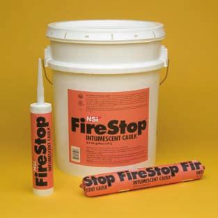
3 Intumescent Caulk AND SILICONE (Continued on page 9) FireStop Intumescent Caulk NSi FireStop Intumescent Caulk is water-based, single component elastomeric sealant intended for use as a firestop system component. It forms an economical yet durable, flexible and watertight bond with most construction materials. It is applied independently for caulk and walk systems or over mineral wool or backer rod to seal the openings where building services such as pipes and cables penetrate fire rated assemblies. Will not crack or crumble as the physical properties remain stable over time. It tools easily and cleans up with water. May be applied by caulking gun or trowel. ASTM E 81 and UL 179. CATALOG UPC No. CODE Description CTN. Qty. Lbs./CTN. FSIC FireStop Intumescent Caulk in 10. fl. oz. cartridges (0 ml) 1 5 FSIC FireStop Intumescent Caulk in 0 oz. foil packs (600 ml) 1 19 FSIC FireStop Intumescent Caulk in.5 US gallon pails (17L) 1 8 FireStop Silicone NSi FireStop Silicone is a primerless, single component silicone sealant. The sealant cures to a durable, flexible silicone rubber when exposed to atmospheric moisture. It is designed for economical use in joint and service penetration firestop configurations and forms a watertight bond with most construction materials. In most cases, no primer is required. NSi FireStop Silicone is designed to tool easily. It will not crack or crumble as its physical properties remain stable over time. It may be applied over a wide temperature range, 0 F to 10 F (-18 C to 50 C), allowing it to be applied in any season. It will remain flexible indefinitely between temperatures of -50 F and 00 F (-5 C and 19 C). May be applied by caulking gun or trowel. ASTM E 81 and UL 179. CATALOG UPC No. CODE Description CTN. Qty. Lbs./CTN. FSS FireStop Silicone in 10. fl. oz. cartridges (0 ml) 1 5 FSS FireStop Silicone in 0 oz. foil packs (600 ml) 1 19 FSS FireStop Silicone in.5 US gallon pails (17L) 1 8 December NSi 1


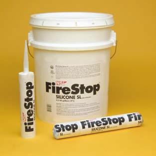
4 Silicone SL, Fireblock81, Fireblock16 (Continued on page 0) FireStop Silicone SL NSi FireStop Silicone SL is a primerless, single component self-levelling silicone sealant. The sealant cures to a durable, flexible silicone rubber when exposed to atmospheric moisture. It is designed for economical use in joint and service penetration firestop configurations and forms a watertight bond with most construction materials. In most cases, no primer is required. FireStop Silicone SL is designed to self-level. No tooling is required. It will not crack or crumble as its physical properties remain stable over time. It may be applied over a wide temperature range, 0 F to 10 F (-18 C to 50 C), allowing it to be applied in any season. It will remain flexible indefinitely between temperatures of -50 F and 00 F (-5 C and 19 C). May be applied by caulking gun or trowel. ASTM E 81 and UL 179. CATALOG UPC No. CODE Description CTN. Qty. Lbs./CTN. FSSL FireStop Silicone SL in 10. fl. oz. cartridges (0 ml) 1 5 FSSL FireStop Silicone SL in 0 oz. foil packs (600 ml) 1 19 FSSL FireStop Silicone SL in.5 US gallon pails (17L) 1 8 FIRESTOP81 RESIDENTIAL & COMMERCIAL FIRE STOP NSi FireStop81 Fire stopping caulk is a single component, noncombustible, non-intumescent material for residential and commercial applications. Colored red for easy inspection, FireStop81 creates an effective barrier against flames, smoke, and toxic gasses and has superior adhesion and gunnability. FireStop81 is for use in annular spaces around wires and pipes, in one- and two-hour fire rated assemblies. It restores the integrity of firestops in residential and commercial construction. Meets UL 179/ ASTM-E81 standards. CATALOG UPC no. CODE Description CTN. Qty. Lbs./CTN. FS oz Caulk Tube, Red, non-intumescent commercial fire stop 1 1 FIREBLOCK16 RESIDENTIAL RATED FIRE BLOCK NSi FireBlock16 Fire-blocking caulk is a single component, noncombustible material for residential applications. Colored red for easy inspection, FireBlock16 creates an effective barrier against flames, smoke, and toxic gasses and has superior adhesion and gunnability. FireBlock16 is for use in annular spaces around wires, pipes, ducts, vents and other penetrating items at ceiling and floor openings; and room to room in wood and steel frame constructions. It restores the integrity of fireblocks in one and two family construction. Exceeds ASTM-E16 standards for fireblocking residential requirements prescribed by all major-model building codes, and also meets or exceeds requirements of UBC, BOCA, SBC, IRC, NYS and MA codes. Meets UL 179/ ASTM-E16 standards. CATALOG UPC No. CODE Description CTN. Qty. Lbs./CTN. FS oz Caulk Tube, Red; Non-combustible for residential applications 1 1 NSi Fax: Phone:


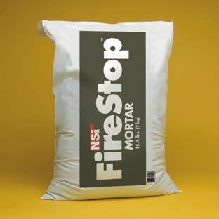
5 Fire Rated Putty Sticks, Putty Pads and MORTAR (Continued on page 0) Fire Rated Putty Sticks and Putty Pads NSi Fire Rated Putty is a moldable non-curing, one-component fire rated material for through penetration fire stop systems. In the event of a fire, Putty will expand when exposed to fire, forming an insulating char, which prevents the spread of flames, smoke, gas and water through penetration openings. Installation is easy as there are no additives, there is no mixing and no curing time is required. The putty is applied by hand and adheres to all common building surfaces. Putty can be installed in confined or occupied spaces since there are no volatile solvents or asbestos fillers. NSi Putty systems are rated up to hours in accordance with ASTM E 81, UL 179 and ULC/CAN-S115-M standards. NSi Fire Rated Putty is available in sticks or pads. Moldable Putty Pads are available in two sizes, 6 x 7 x 1 /8 or 7 x 7 x 1 /8, and are classified as a wall opening protective material. Use them to protect metal electrical cabinets, outlet boxes and mechanical cabinets. STC Rating 9. Putty Sticks are 1 1 / in diameter x 10 inches long, and are classified as a fill, void or cavity material by UL. Use them to seal around cable, electrical conduit and metal pipe to prevent passage of smoke, flame and toxic gases. They will not dry out and can be reused as additional penetrating items are installed or removed. CATALOG UPC No. CODE Description CTN. Qty. Lbs./CTN. FSPS Putty sticks 1 1 / diameter x 10 long (18 cu. in.) Red 1 1 FSPP Putty pads 6 x 7 Red 0 8 FSPP Putty pads 7 x 7 Red 0 9 FireStop Mortar NSi FireStop Mortar is a single component non-combustible fiber reinforced, foamed cement mortar. It is intended to provide economical, non-combustible and tight-fitting firestops at openings and penetrations through fire-rated wall and floor assemblies. FireStop Mortar powder mixes easily to form a shaving cream-like, non-slumping paste. This feature permits easy installation with a minimum of damming. When cured, FireStop Mortar is self-supporting and therefore may be used for large openings where other firestopping materials are impractical. It requires and contains no solvents and is comprised of materials of low toxicity. It mixes and trowels easily and tools are cleaned with water. Dust protection is recommended. The color is a distinctive charcoal (dark grey). ASTM E 81 and UL 179. Coverage per bag is 850 cn in. or 0.9 cn ft. CATALOG UPC No. CODE Description CTN. Qty. Lbs./CTN. FSM 0559 FireStop Mortar in 15.5 lb. (7 kg) bags December NSi


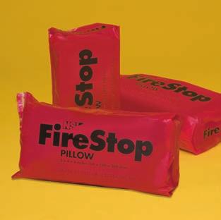
6 Mineral Wool and pillows (Continued on page 1) FireStop Mineral Wool NSi FireStop Mineral Wool is a pre-formed, non-combustible mineral wool insulation. It is a semi-rigid combination of basaltic mineral wool and proprietary binders. The mineral wool is pre-cut into various widths and depths in 8 inch lengths for ease of handling and immediate installation. It is intended for use as a firestop system component and forming material in tested firestop systems and designs. It is friction fitted into openings, joints, gaps, spaces and voids in fire rated assemblies. It is usually used in conjunction with firestop sealant products such as Silicone, Silicone SL and Intumescent Caulk. CATALOC UPC No. CODE Description CTN. Qty. Lbs./CTN. FSMW FireStop Mineral Wool in 5 lb. bags 1 5 FireStop Pillows NSi FireStop Pillows are a single step firestop system component. They are intended for wall and/or floor openings through fire separations where temporary or permanent firestops are required. They are ideal where cable retrofitting is frequent and anticipated. These pillows allow for quick and clean single product installation. Pillows are self-supporting no wire lath or mesh is required. They are to be packed tightly into the voids between penetrating items and the perimeter of the opening. During a fire, the intumescent component within each pillow dramatically expands to seal the opening from fire, thereby maintaining the integrity of the fire separation. FireStop Pillows consist of an intumescent layer sandwiched between non-combustible insulation, all enclosed in a hermetically sealed polyethylene shell. No sealant or putty is required. Easy to install, easy to remove a quick and clean single product installation. ASTM E 81 and UL 179. CATALOG UPC No. CODE Description CTN. Qty. Lbs./CTN. FSP FireStop Pillows in. x in. x 8 in. (50 x 100 x 00 mm.) 5 7 NSi Phone: Fax:


7 FireStop Box and cover Guards FireStop Box Guards NSi FireStop Box Guards are one component fire rated pads made of highly intumescent firestop material for use in electrical boxes. They are inserted in the box and adhere to the inside back wall. FireStop Box Guards are easy to install and very cost effective. When exposed to fire they expand, forming a char that will seal off the opening, prevent the spread of fire and limit the temperature rise on the unexposed surfaces. When used as directed, the horizontal separation between outlet boxes on opposite sides of the wall may be less than inches, provided that the boxes are not back-to-back. FireStop Box Guards are classified by UL under Wall Opening Protective Material as found in the Fire Resistance Directory. Available in two sizes to suit single and double boxes. STC Rating 55. CATALOG UPC No. CODE Description CTN. Qty. Lbs./CTN. FSBG Single box insert 50 FSBG Double box insert 50 7 FireStop Cover Guards NSi FireStop Cover Guards are one component fire rated gaskets made of highly intumescent firestop material for use in electrical boxes. They are mounted on the inside of the cover plate and installed at the same time as the cover plate. When exposed to fire they expand, forming a char that will seal off the opening, prevent the spread of fire and limit the temperature rise on the unexposed surfaces. NSi FireStop Cover Guards are easy to install and very cost effective. Excellent for use when addressing the inch rule. They are used when electrical boxes are installed in rated walls facing opposite directions and horizontally separated by less than inches. They can also be used as a solution for standard electrical boxes when the 100 square inch rule is violated. Exceptional for safe, retrofit applications. Can be used for both metal and plastic cover plates. FireStop Cover Guards are available as single switch, double switch, single receptacle, single décor and double décor. An economical alternative to putty pads. STC Rating 5. CATALOG UPC No. CODE Description CTN. Qty. Lbs./CTN. FSSRC Single receptacle cover guard 50 FSDRC Double receptacle cover guard 50 FSSSC 0556 Single switch 50 FSDSC 0556 Double switch 50 FSSDC 0556 Single décor 50 FSDDC Double décor 50 December NSi 5
8 Application Designs and Reference Guide Conduit and EMT MAX. Pen. Rating Max. Floor or NSi FireStop Application system Page Diameter (hr.) Opening Wall System Product(S) Required Thickness No. No. 6 in. conduit & 0 in. to Floor concrete, NSi FireStop Min. 1 / in. thick within annulus flush C-AJ EMT or smaller in. Wall concrete Intumescent Caulk with top of floor or both surfaces of wall annulus or concrete block NSi FireStop Mineral Wool Min. in. thick packed into opening (wall both sides) 6 in. conduit & 0 in. to Floor concrete ( 1 / in. min.), NSi FireStop Min. 1 / in. thick within annulus flush C-AJ EMT or smaller 1 / in. Wall concrete, concrete Intumescent Caulk with top of floor or both surfaces of wall annulus block or precast units NSi FireStop Mineral Wool Min. in. thick packed into opening (wall both sides) 6 in. conduit & 0 in. to Floor concrete ( 1 / in. min.), NSi FireStop Min. 1 / in. thick within annulus flush C-AJ EMT or smaller 7 /8 in. Wall concrete, concrete block Intumescent Caulk with top of floor or both surfaces of wall annulus or precast units in. conduit & 0 in. to Floor concrete, NSi FireStop Silicone Min. 1 / in. thick within annulus flush C-AJ in. EMT or 1 / in. Wall concrete, concrete or Silicone SL with top of floor or both surfaces of wall smaller annulus block or precast units NSi FireStop Mineral Wool Min. in. thick packed into opening (wall both sides) 8 in. diameter 0 in. to Floor concrete NSi FireStop Silicone SL Min. 1 / in. thick within annulus flush with top of floor C-AJ or smaller 7 /8 in. NSi FireStop Mineral Wool Min. in. thick packed into opening annulus 6 in. conduit & 0 in. to Wall gypsum board NSi FireStop Min. 1 1 / in. thick within annulus W-L-19 1 EMT or smaller 1 / in. Intumescent Caulk flush with both surfaces of wall annulus 6 in. conduit & 0 in. to Wall gypsum board NSi FireStop Min. 5 /8 in. thick within annulus W-L EMT or smaller 1 1 / in. Intumescent Caulk flush with both surfaces of wall annulus NSi FireStop Mineral Wool Min. in. thick packed into opening on both sides of wall 6 in. conduit & 1 1 / in. to Wall gypsum board NSi FireStop Min. 5 /8 in. thick within annulus W-L EMT or smaller 1 / in. Intumescent Caulk flush with both surfaces of wall annulus in. conduit & 0 in. to Wall gypsum board NSi FireStop Min. 1 1 / in. thick within annulus W-L-18 1 EMT or smaller 1 / in. Intumescent Caulk flush with both surfaces of wall annulus in. conduit & 1 & 0 in. to Wall gypsum board NSi FireStop Silicone Min. 5 /8 in. thick within annulus W-L-17 1 EMT or smaller 1 7 /8 in. flush with both surfaces of wall annulus in. conduit & 1 1 / in. Floor lumber NSi FireStop Silicone Min. 1 1 /8 in. thick within annulus on top of floor F-C EMT or smaller annulus Ceiling gypsum board Min. 1 / in. thick within annulus on bottom surface of ceiling in. conduit & 1 0 in. to Floor lumber NSi FireStop Min. / in. thick within annulus on top of floor F-C EMT or smaller 1 / in. Ceiling gypsum board Intumescent Caulk Min. 5 /8 in. thick within annulus on annulus bottom surface of ceiling in. conduit & 1 1 / in. Floor lumber NSi FireStop Silicone Min. 1 1 /8 in. thick within annulus on top of floor F-C EMT or smaller annulus Ceiling gypsum board A generous bead within annulus flush with in wall bottom surface of lower top plate Non-Metallic Conduit MAX. Pen. Rating Max. Floor or NSi FireStop Application system Page Diameter (hr.) Opening Wall System Product(S) Required Thickness No. No., PVC, CPVC & / in. to Floor concrete, NSi FireStop Silicone Min. 1 in. thick within annulus flush with C-AJ Rigid conduit & 1 /8 in Wall concrete or Silicone SL top of floor or both surfaces of wall 1 1 / in. EMT or smaller annulus or concrete block NSi FireStop Mineral Wool Min. in. thick packed into opening (wall both sides), PVC, CPVC & 1 / in. to Wall gypsum board NSi FireStop Silicone Min. / in. thick within annulus W-L-9 18 Rigid conduit 1 1 /8 in. wood flush with both surfaces of wall or smaller annulus NSi FireStop Mineral Wool Min. in. thick packed into opening on both sides of wall, PVC, CPVC, 1 1 / in. Floor lumber NSi FireStop Min. / in. thick within annulus on top of floor F-C ABS & Rigid nom. Ceiling gypsum board Intumescent Caulk Min. 5 /8 in. thick within annulus conduit or smaller annulus on bottom surface of ceiling 6 NSi Phone: Fax:
9 Application Designs and Reference Guide Cables/Larger Openings Type of Rating Max. Floor or NSi FireStop Application system Page penetration (hr.) Opening Wall System Product(S) Required Thickness No. No. Coaxial, fiber 88 sq. in. Floor concrete, NSi FireStop Pillows Installed with 8 in. dimension projecting through C-AJ optic & AWG Wall concrete or floor or wall & centered within opening concrete block Coaxial, fiber 88 sq. in. Floor concrete, NSi FireStop Pillows Installed with 8 in. dimension projecting through C-AJ optic, AWG Wall concrete or floor or wall & centered within opening & data cable concrete block 500 MCM, 10, 1 1 /8 in. nom. Floor lumber, NSi FireStop Silicone Min. 1 1 /8 in. thick within annulus on top of floor F-C , AWG annulus Ceiling gypsum board Min. 1 / in. thick within annulus on bottom & RG 11/U out of wall surface of ceiling 500 MCM,, 1 1 /8 in. nom. Floor lumber, NSi FireStop Silicone Min. 1 1 /8 in. thick within annulus flush with top of floor F-C AWG & annulus Ceiling gypsum board A generous bead within annulus flush with RG 11/U in wall bottom surface of lower top plate Cables 1 0 in. to. Floor lumber NSi FireStop Min. 1 1 / in. thick within annulus on top of floor F-C / in Ceiling gypsum board Intumescent Caulk Min. 1 / in. thick within annulus on bottom annulus surface of ceiling 500 MCM,, 1 / in. nom. Wall concrete or NSi FireStop Silicone Min. / in. thick within annulus flush with W-J-19 1, 10 AWG or annulus concrete block both surfaces of wall smaller, RG/U NSi FireStop Mineral Wool Min. in. thick packed into opening on both sides of wall 500 MCM, 1 & 1 / in. Wall gypsum board NSi FireStop Silicone hr. - min. 1 in. within annulus on both surfaces of wall W-L-5 AWG & nom. 1 hr. - min. 1 / in. within annulus on RG 11/U annulus both surfaces of wall 500 MCM,, 1 & 1 / in. Wall gypsum board NSi FireStop Silicone Min. / in. thick within annulus flush with W-L-5 1, 10 AWG nom. both surfaces of wall or smaller, RG/U annulus NSi FireStop Mineral Wool Min. in. thick packed into opening on both sides of wall MULTIPLE PENETRATIONS type of Rating Max. Floor or NSi FireStop Application system Page penetration (hr.) Opening Wall System Product(S) Required Thickness No. No. in. conduit &. sq. ft. Floor concrete, NSi FireStop Silicone Min. 1 / in. thick within annulus flush with C-AJ EMT or smaller, Wall concrete, concrete or Silicone SL top of floor or both surfaces of wall cables & cable tray block or precast units NSi FireStop Mineral Wool Min. in. thick packed into opening (wall both sides) in. conduit &. sq. ft. Floor concrete, NSi FireStop Mortar Min. in. thick flush with top of floor C-AJ EMT or smaller, Wall concrete or & both surfaces of wall cables & cable tray concrete block in. conduit & 1 & 1.9 sq. ft. Wall gypsum board NSi FireStop Mortar hr. - min. 1 / in. flush with both surfaces of wall W-L EMT or smaller, NSi FireStop Mineral Wool 1 hr. - min. 1 / in. flush with both surfaces of wall cables & cable tray NSi FireStop Silicone in. conduit sq. ft. Floor concrete, NSi FireStop Mortar Fill opening to min. depth of in. AD/PHV 8 or smaller, Wall concrete cables & cable tray December NSi 7
10 Conduit and EMT Systems UL System No. C-AJ-1509 F Rating hr., T Rating 0 hr. 1 b 1. Floor or wall assembly Minimum 1 / in. thick reinforced normal weight concrete. Wall may also be constructed of any UL Classified concrete blocks. Maximum diameter of opening is 8 in. See Concrete Blocks (CAZT) category in the Fire Resistance Directory for names of manufacturers. a a. Through Penetrant One metallic pipe, conduit or tubing to be installed either concentrically or eccentrically within the firestop system. Pipe, conduit or tubing to be rigidly supported on both sides of floor or wall assembly. A maximum of one pipe, conduit or tubing to be installed within the opening. The space between the pipe, conduit or tubing and the periphery of opening shall be a minimum of 0 in. to a maximum of in. The following types and sizes of metallic pipes, conduits or tubing may be used: a) Steel pipe Nom. in. diameter (or smaller) Schedule 10 (or heavier) steel pipe b) Conduit Nom. 6 in. diameter (or smaller) electrical metallic tubing or steel conduit c) Copper tubing Nom. 6 in. diameter (or smaller) Type L (or heavier) copper tubing d) Copper pipe Nom. 6 in. diameter (or smaller) Regular (or heavier) copper pipe. b. Firestop System The firestop system shall consist of the following: a) Packing material NSi FireStop Mineral Wool. Minimum in. thickness of minimum pcf mineral wool batt insulation firmly packed into opening as a permanent form. Packing material to be recessed from top surface of floor or from both surfaces of wall as required to accommodate the required thickness of fill material b) Fill, void or cavity material NSi FireStop Intumescent Caulk. Minimum 1 / in. thickness of fill material applied within the annulus, flush with top surface of floor or with both surfaces of wall. At the point contact location between through penetrant and concrete, a minimum 1 / in. diameter bead of fill material shall be applied at the concrete/through penetrant interface on the top surface of floor and on both surfaces of wall. UL System No. C-AJ-1510 F Rating hr., T Rating 0 hr. 1 b a 1. Floor or wall assembly Minimum 1 / in. thick reinforced lightweight or normal weight ( pcf) structural concrete. Floor may also be constructed of any minimum 6 in. thick UL Classified hollow-core precast concrete units. Wall may also be constructed of any UL Classified concrete blocks. Maximum diameter of opening is 6 1 / in. Maximum diameter of opening in floors constructed of hollow-core is 7 in. See Concrete Blocks (CAZT) or Precast Concrete Units (CFTV) category in the Fire Resistance Directory for names of manufacturers.. Steel Sleeve (optional) Nom. 6 in. diameter (or smaller) Schedule 10 (or heavier) steel pipe cast or grouted into floor or wall assembly, flush with floor or wall surfaces. b a. Through Penetrant One metallic pipe, conduit or tubing, rigidly supported on both sides of floor or wall assembly. The annular space between the pipe or conduit and the periphery of opening shall be a minimum of 0 in. (point contact) to a maximum of 1 / in. The following types and sizes of metallic pipes, conduits or tubing may be used: a) Copper tubing Nom. 6 in. diameter (or smaller) Type L (or heavier) copper tube b) Steel pipe Nom. in. diameter (or smaller) Schedule 10 (or heavier) steel pipe c) Conduit Nom. 6 in. diameter (or smaller) steel electrical metallic tubing (EMT) d) Iron pipe Nom. in. diameter (or smaller) cast or ductile iron pipe.. Firestop System The firestop system shall consist of the following: a) Packing material NSi FireStop Mineral Wool. Minimum.5 pcf mineral wool batt insulation, tightly compressed and firmly packed into opening as a permanent form to a minimum depth of 1 / in. Packing material to be recessed from top surface of floor or from both surfaces of wall as required to accommodate the required thickness of sealant b) Fill, void or cavity material NSi FireStop Intumescent Caulk. Minimum 1 / in. thickness of caulk applied within the annulus, flush with top surface of floor or with both surfaces of wall. In floors constructed of hollow-core precast concrete units, fill material installed symmetrically on both sides of floor. Additional material installed to form a minimum 1 / in. crown bead at the point contact location between the pipe and periphery of the opening. For vertical installations, sealant to be applied symmetrically on both sides of wall. 8 NSi Phone: Fax:
11 Conduit and EMT Systems UL System No. C-AJ-1511 F Rating hr., T Rating 0 hr Floor or wall assembly Minimum 1 / in. thick reinforced lightweight or normal weight ( pcf) concrete floor. Floor may also be constructed of any minimum 6 in. thick UL Classified hollow-core precast concrete units. Wall may also be constructed of any UL Classified concrete blocks. Maximum diameter of opening is 7 /8 in. Maximum diameter of opening in floors constructed of hollow-core is 7 in. See Concrete Blocks (CAZT) or Precast Concrete Units (CFTV) category in the Fire Resistance Directory for names of manufacturers.. Through Penetrant One metallic pipe, conduit or tubing to be installed within the firestop system. Pipe, conduit or tubing to be rigidly supported on both sides of floor or wall assembly. The annular space between the pipe or conduit and the periphery of opening shall be a minimum of 0 in. (point contact) to a maximum of 7 /8 in. The following types and sizes of metallic pipes, conduits or tubing may be used: a) Steel pipe Nom. in. diameter (or smaller) Schedule 10 (or heavier) steel pipe b) Iron pipe Nom. in. diameter (or smaller) cast or ductile iron pipe c) Conduit Nom. 6 in. diameter (or smaller) steel electrical metallic tubing or steel conduit d) Copper pipe or tubing Nom. 6 in. diameter (or smaller) Type L (or heavier) copper tubing.. Fill, void or cavity material NSi FireStop Intumescent Caulk. Minimum 1 / in. thickness of caulk applied within the annulus, flush with top surface of floor or with both surfaces of wall. In floors constructed of hollow-core precast concrete units, fill material installed symmetrically on both sides of floor. Additional material installed to form a minimum 1 / in. crown bead at the point contact location between the pipe and periphery of the opening. For vertical installations, sealant to be applied symmetrically on both sides of wall. 1 b a b a UL System No. C-AJ-1508 F Rating hr., T Rating 0 hr. 1. Floor or wall assembly Minimum 1 / in. thick reinforced normal weight ( pcf) concrete floor or minimum 5 in. thick reinforced normal weight concrete wall. Floor may also be constructed of any minimum 6 in. thick UL Classified hollow-core precast concrete units. Wall may also be constructed of any UL Classified concrete blocks. Maximum diameter of opening is 0 in. If firestop system is installed within a hollow-core precast concrete unit, maximum diameter of opening shall be 7 in. See Concrete Blocks (CAZT) or Precast Concrete Units (CFTV) category in the Fire Resistance Directory for names of manufacturers.. Metallic Sleeve (optional) Nom. 0 in. diameter (or smaller) Schedule 0 (or heavier) steel sleeve cast or grouted into floor or wall assembly, flush with floor or wall surfaces.. Through Penetrant One metallic pipe or conduit to be installed either concentrically or eccentrically within the firestop system. The annular space between the pipe or conduit and the periphery of opening shall be a minimum of 0 in. (point contact) to a maximum of 1 / in. Pipe or conduit to be rigidly supported on both sides of floor or wall assembly. The following types and sizes of metallic pipes or conduits may be used: a) Steel pipe Nom. 16 in. diameter (or smaller) Schedule 0 (or heavier) steel pipe b) Iron pipe Nom. 16 in. diameter (or smaller) cast or ductile iron pipe c) Conduit Nom. in. diameter (or smaller) steel electrical metallic tubing or nom. 6 in. diameter steel conduit.. Firestop System The firestop system shall consist of the following: a) Packing material NSi FireStop Mineral Wool. Minimum in. thickness of minimum pcf mineral wool batt insulation firmly packed into opening as a permanent form. Packing material to be recessed from top surface of floor or from both surfaces of wall as required to accommodate the required thickness of fill material. When the floor is constructed of hollow-core precast concrete units, packing material shall be recessed from both surfaces of floor to accommodate the required thickness of fill material b) Fill, void or cavity material Sealant NSi FireStop Silicone SL (for floors only) and NSi FireStop Silicone (for floors, hollow-core pre-cast concrete units and walls). Minimum 1 / in. thickness of fill material applied within the annulus, flush with top surface of floor or with both surfaces of wall. When the floor is constructed of hollow-core precast concrete units, fill material shall be installed symmetrically on both sides of floor, flush with floor surface. At the point contact location between through penetrant and concrete, a minimum /8 in. diameter bead of fill material shall be applied at the concrete/through penetrant interface on the top surface of floor and on both surfaces of wall. December NSi 9
12 Conduit and EMT Systems 1 b a b UL System No. C-AJ-1507 F Rating hr., T Rating 0 hr. 1. Floor or wall assembly Minimum 1 / in. thick reinforced normal weight concrete. Floor may also be constructed of any minimum 6 in. thick UL Classified hollow-core precast concrete units. Wall may also be constructed of any UL Classified concrete blocks. Maximum diameter of opening is 1 1 / in. If firestop system is installed within hollow-core concrete unit, maximum diameter of opening shall be 7 in. See Concrete Blocks (CAZT) or Precast Concrete Units (CFTV) category in the Fire Resistance Directory for names of manufacturers.. Through Penetrant One metallic pipe or conduit to be installed either concentrically or eccentrically within the firestop system. The annular space between pipes or conduits and the periphery of opening shall be a minimum of 0 in. (point contact) to a maximum of 7 /8 in. Pipe or conduit to be rigidly supported on both sides of floor or wall assembly. The following types and sizes of metallic pipes or conduits may be used: a) Steel pipe Nom. 8 in. diameter (or smaller) Schedule 0 (or heavier) steel pipe b) Iron pipe Nom. 8 in. diameter (or smaller) cast or ductile iron pipe c) Conduit Nom. in. diameter (or smaller) steel electrical metallic tubing or nom. 6 in. diameter steel conduit.. Firestop System The firestop system shall consist of the following: Firestop Configuration A: a) Packing material NSi FireStop Mineral Wool. Minimum in. thickness of minimum pcf mineral wool batt insulation firmly packed into opening as a permanent form. Packing material to be recessed from bottom surface of floor or from both surfaces of wall as required to accommodate the required thickness of fill material. When the floor is constructed of hollow-core precast concrete units, packing material shall be recessed from bottom surface of floor to accommodate the required thickness of fill material and installed flush with top surface of floor. b) Fill, void or cavity material Sealant NSi FireStop Silicone (floors, pre-cast concrete units and walls). Minimum 1 / in. thickness of fill material applied within the annulus, flush with bottom surface of floor or with both surfaces of wall assembly. At the point contact location between through penetrant and concrete, a minimum 1 / in. diameter bead of fill material shall be applied at the concrete/ through penetrant interface on the bottom surface of floor and on both surfaces of wall. Firestop Configuration B: a) Packing material NSi FireStop Mineral Wool. Minimum in. thickness of minimum pcf mineral wool batt insulation firmly packed into opening as a permanent form. Packing material to be recessed from top surface of floor or from both surfaces of wall as required to accommodate the required thickness of fill material. When the floor is constructed of hollow-core precast concrete units, packing material shall be recessed from both surfaces of floor to accommodate the required thickness of fill material. b) Fill, void or cavity material Sealant NSi FireStop Silicone SL (floors only) and NSi FireStop Silicone (floors, pre-cast concrete units and walls). Minimum 1 / in. thickness of fill material applied within the annulus, flush with top surface of floor or with both surfaces of wall assembly. When the floor is constructed of hollow-core precast concrete units, fill material shall be installed flush with both surfaces of floor. At the point contact location between through penetrant and concrete, a minimum 1 / in. diameter bead of caulk grade fill material shall be applied at the concrete/through penetrant interface on the top surface of floor and on both surfaces of wall and hollow-core precast concrete units. 1a 1b UL System No. W-L-19 F Rating hr., T Rating 0 hr. 1. Wall Assembly The fire-rated gypsum wallboard/stud wall assembly shall be constructed of the materials and in the manner described in the individual U00 or U00 Series Wall or Partition Design in the UL Fire Resistance Directory and shall include the following construction features: a) Studs Wall framing may consist of either wood studs or steel channel studs. Wood studs to consist of nom. x in. lumber spaced 16 in. oc. Steel studs to be minimum 5 /8 in. wide and spaced maximum in. oc. When steel studs are used and the diameter of openings exceeds the width of stud cavity, the opening shall be framed on all sides using lengths of steel stud installed between vertical studs and screw-attached to the studs at each end. The framed opening in the wall shall be to 6 in. wider and to 6 in. higher than the diameter of the penetrating item such that, when the penetrating item is installed in the opening, a to in. clearance is present between the penetrating item and the framing on all four sides. b) Wallboard, Gypsum 5 /8 in. thick, ft. wide with square or tapered edges. The gypsum wall board type, thickness, number of layers, fastener type and sheet orientation shall be as specified in the individual U00 or U00 Series Design in the UL Fire Resistance Directory. Maximum diameter of opening is 6 5 /8 in.. Through Penetrant One metallic pipe, conduit or tubing to be installed either concentrically or eccentrically within the firestop system. The annular space between pipes, conduits or tubing and the periphery of opening shall be a minimum of 0 in. (point contact) to a maximum of 1 / in. Pipe, tubing or conduit to be rigidly supported on both sides of wall assembly. The following types and sizes of metallic pipes, tubing or conduits may be used: a) Steel pipe Nom. in. diameter (or smaller) Schedule 5 (or heavier) steel pipe b) Iron pipe Nom. in. diameter (or smaller) cast or ductile iron pipe c) Conduit Nom. 6 in. diameter (or smaller) steel electrical metallic tubing or steel conduit d) Copper Tubing Nom. 6 in. diameter (or smaller) Type L (or heavier) copper tubing e) Copper Pipe Nom. 6 in. diameter (or smaller) Regular (or heavier) copper pipe.. Fill, void or cavity material Sealant NSi FireStop Intumescent Caulk. Minimum 1 1 / in. thickness of fill material applied within the annulus, flush with both surfaces of wall. At the point contact location between through penetrant and gypsum wall board, a minimum 1 / in. diameter bead of fill material shall be applied at the gypsum wallboard/through penetrant interface on both surfaces of wall. 10 NSi Phone: Fax:
13 Conduit and EMT Systems UL System No. W-L-150 F Rating hr., T Rating 0 hr. 1a 1b 1. Wall Assembly The fire-rated gypsum wallboard/stud wall assembly shall be constructed of the materials and in the manner described in the individual U00 or U00 Series Wall or Partition Design in the UL Fire Resistance Directory and shall include the following construction features: a) Studs Wall framing may consist of either wood studs or steel channel studs. Wood studs to consist of nom. x in. lumber spaced 16 in. oc. Steel studs to be minimum 5 /8 in. wide and spaced maximum in. oc. When steel studs are used and the diameter of openings exceeds the width of stud cavity, the opening shall be framed on all sides using lengths of steel stud installed between vertical studs and screw-attached to the studs at each end. The framed opening in the wall shall be to 6 in. wider and to 6 in. higher than the diameter of the penetrating item such that, when the penetrating item is installed in the opening, a to in. clearance is present between the penetrating item and the framing on all four sides b) Wallboard, Gypsum 5 /8 in. thick, ft. wide with square or tapered edges. The gypsum wall board type, thickness, number of layers, fastener type and sheet orientation shall be as specified in the individual U00 or U00 Series Design in the UL Fire Resistance Directory. Maximum diameter of opening is 7 5 /8 in.. Through Penetrant One metallic pipe, conduit or tubing to be installed either concentrically or eccentrically within the firestop system. The annular space between pipes, conduits or tubing and the periphery of opening shall be a minimum of 0 in. (point contact) to a maximum of 1 1 / in. Pipe, tubing or conduit to be rigidly supported on both sides of wall assembly. The following types and sizes of metallic pipes, tubing or conduits may be used: a) Steel pipe Nom. in. diameter (or smaller) Schedule 5 (or heavier) steel pipe b) Iron pipe Nom. in. diameter (or smaller) cast or ductile iron pipe c) Conduit Nom. 6 in. diameter (or smaller) steel electrical metallic tubing or steel conduit d) Copper Tubing Nom. 6 in. diameter (or smaller) Type L (or heavier) copper tubing e) Copper Pipe Nom. 6 in. diameter (or smaller) Regular (or heavier) copper pipe.. Packing Material NSi FireStop Mineral Wool. Minimum in. thickness of minimum pcf mineral wool batt insulation firmly packed into opening as a permanent form. Packing material to be recessed from both surfaces of the wall by 5 /8 in.. Fill, void or cavity material Sealant NSi FireStop Intumescent Caulk. Minimum 5 /8 in. thickness of fill material applied within the annulus, flush with both surfaces of wall. Additional material to be installed such that a 1 / in. crown bead is formed around the penetrating item. UL System No. W-L-151 F Rating 1 hr., T Rating 0 hr. 1a 1b 1. Wall Assembly The 1 hr. fire-rated gypsum wallboard/stud wall assembly shall be constructed of the materials and in the manner described in the individual U00 or U00 Series Wall or Partition Design in the UL Fire Resistance Directory and shall include the following construction features: a) Studs Wall framing may consist of either wood studs or steel channel studs. Wood studs to consist of nom. x in. lumber spaced 16 in. oc. Steel studs to be minimum 5 /8 in. wide and spaced maximum in. oc. When steel studs are used and the diameter of openings exceeds the width of stud cavity, the opening shall be framed on all sides using lengths of steel stud installed between vertical studs and screw-attached to the studs at each end. The framed opening in the wall shall be to 6 in. wider and to 6 in. higher than the diameter of the penetrating item such that, when the penetrating item is installed in the opening, a to in. clearance is present between the penetrating item and the framing on all four sides b) Wallboard, Gypsum 5 /8 in. thick, ft. wide with square or tapered edges. The gypsum wall board type, thickness, number of layers, fastener type and sheet orientation shall be as specified in the individual U00 or U00 Series Design in the UL Fire Resistance Directory. Maximum diameter of opening is / in. for steel stud walls. Maximum diameter opening is 1 1 / in. for wood stud walls.. Through Penetrant One metallic pipe, conduit or tubing to be installed either concentrically or eccentrically within the firestop system. The annular space between pipes, conduits or tubing and the periphery of opening shall be a minimum of 1 / in. to a maximum of 1 / in. Pipe, tubing or conduit to be rigidly supported on both sides of wall assembly. The following types and sizes of metallic pipes, tubing or conduits may be used: a) Steel pipe Nom. in. diameter (or smaller) Schedule 5 (or heavier) steel pipe b) Iron pipe Nom. in. diameter (or smaller) cast or ductile iron pipe c) Conduit Nom. 6 in. diameter (or smaller) steel electrical metallic tubing or steel conduit d) Copper Tubing Nom. 6 in. diameter (or smaller) Type L (or heavier) copper tubing e) Copper Pipe Nom. 6 in. diameter (or smaller) Regular (or heavier) copper pipe.. Fill, void or cavity material Sealant NSi FireStop Intumescent Caulk. Minimum 5 /8 in. thickness of fill material applied within the annulus, flush with both surfaces of wall. December NSi 11
14 Conduit and EMT Systems 1a 1b UL System No. W-L-18 F Rating hr., T Rating 0 hr. 1. Wall Assembly The hr. fire-rated gypsum wallboard/stud wall assembly shall be constructed of the materials and in the manner described in the individual U00 or U00 Series Wall or Partition Design in the UL Fire Resistance Directory and shall include the following construction features: a) Studs Wall framing may consist of either wood studs or steel channel studs. Wood studs to consist of nom. x in. lumber spaced 16 in. oc. with nom. x in. lumber end plates and cross braces. Steel studs to be minimum 5 /8 in. wide and spaced maximum in. oc. When steel studs are used and the diameter of openings exceeds the width of stud cavity, the opening shall be framed on all sides using lengths of steel stud installed between vertical studs and screw-attached to the studs at each end. The framed opening in the wall shall be to 6 in. wider and to 6 in. higher than the diameter of the penetrating item, such that when the penetrating item is installed in the opening, a to in. clearance is present between the penetrating item and the framing on all four sides b) Wallboard, Gypsum 5 /8 in. thick, ft. wide with square or tapered edges. The gypsum wall board type, thickness, number of layers, fastener type and sheet orientation shall be as specified in the individual U00 or U00 Series Design in the UL Fire Resistance Directory. Maximum diameter of opening is 5 in.. Through Penetrant One metallic pipe, conduit or tubing to be installed either concentrically or eccentrically within the firestop system. The annular space between pipes, conduits or tubing and the periphery of opening shall be a minimum of 0 in. (point contact) to a maximum of 1 / in. Pipe, tubing or conduit to be rigidly supported on both sides of wall assembly. The following types and sizes of metallic pipes, tubing or conduits may be used: a) Steel pipe Nom. in. diameter (or smaller) Schedule 5 (or heavier) steel pipe b) Conduit Nom. in. diameter (or smaller) steel electrical metallic tubing or galv. steel conduit c) Copper Tubing Nom. in. diameter (or smaller) Type L (or heavier) copper tubing d) Copper Pipe Nom. in. diameter (or smaller) Regular (or heavier) copper pipe.. Fill, void or cavity material Sealant NSi FireStop Intumescent Caulk. Minimum 1 1 / in. thickness of fill material applied within the annulus, flush with both surfaces of wall. At the point contact location between through penetrant and gypsum wall board, a minimum /8 in. diameter bead of fill material shall be applied at the gypsum wallboard/through penetrant interface on both surfaces of wall. UL System No. W-L-17 F Rating 1 and hr. (See Item 1b), T Rating 0 hr. 1a 1b 1. Wall Assembly The 1 or hr. fire-rated gypsum wallboard/stud wall assembly shall be constructed of the materials and in the manner described in the individual U00 or U00 Series Wall or Partition Design in the UL Fire Resistance Directory and shall include the following construction features: a) Studs Wall framing may consist of either wood studs or steel channel studs. Wood studs to consist of nom. x in. lumber spaced 16 in. oc. with nom. x in. lumber end plates and cross braces. Steel studs to be minimum 5 /8 in. wide and spaced maximum in. oc. b) Wallboard, Gypsum 5 /8 in. thick, ft. wide with square or tapered edges. The gypsum wall board type, thickness, number of layers, fastener type and sheet orientation shall be as specified in the individual U00 or U00 Series Design in the UL Fire Resistance Directory. Maximum diameter of opening is in. The hourly F rating of the firestop system is equal to the hourly fire rating of the wall assembly in which it is installed.. Through Penetrant One metallic pipe, conduit or tubing to be installed either concentrically or eccentrically within the firestop system. The annular space between pipes, conduits or tubing and the periphery of opening shall be a minimum of 0 in. (point contact) to a maximum of 1 7 /8 in. Pipe, tubing or conduit to be rigidly supported on both sides of wall assembly. The following types and sizes of metallic pipes, tubing or conduits may be used: a) Steel pipe Nom. in. diameter (or smaller) Schedule 10 (or heavier) steel pipe b) Iron pipe Nom. in. diameter (or smaller) cast or ductile iron pipe c) Copper Tubing Nom. in. diameter (or smaller) Type L (or heavier) copper tubing d) Copper Pipe Nom. in. diameter (or smaller) Regular (or heavier) copper pipe e) Conduit Nom. in. diameter (or smaller) steel electrical metallic tubing or galv. steel conduit.. Fill, void or cavity material Sealant NSi FireStop Silicone. Minimum 5 /8 in. thickness of fill material applied within the annulus, flush with both surfaces of wall. At the point contact location between through penetrant and gypsum wallboard, a minimum /8 in. dia meter bead of fill material shall be applied at the gypsum wallboard/through penetrant interface on both surfaces of wall. 1 NSi Phone: Fax:
15 Conduit and EMT Systems UL System No. F-C-116 F Rating 1 hr. T Ratings 0, / and 1 hr. (See Item ) 1d 1b 1a 1. Floor-Ceiling Assembly The fire-rated wood joist floor-ceiling assembly shall be constructed of the materials and in the manner specified in the Design No. L51, L51 or L51 in the UL Fire Resistance Directory and shall include the following construction features: a) Flooring System Lumber or minimum 1 / in. plywood subfloor with lumber or minimum / in. plywood finish floor or Floor-Topping Mixture as specified in the individual floor-ceiling design. Maximum diameter of opening is 7 in. b) Wood Joists Nom. x 10 in. lumber joists spaced 16 in. oc. with nom. 1 x in. lumber bridging and with ends firestopped c) Furring Channels (not shown) Resilient galv. steel furring installed perpendicular to wood joists between wallboard and wood joists and spaced maximum in. oc. d) Wallboard, Gypsum Nom. ft. wide x 1 / or 5 /8 in. thick as specified in the individual floor-ceiling design. Wallboard attached to wood joists and furring channels as specified in the individual floor-ceiling design. Maximum diameter of opening is 7 in.. Through Penetrant One metallic pipe, conduit or tubing to be installed approximately midway between wood joists and centered within the firestop system. Diameter of openings hole-sawed through flooring system and through gypsum wallboard ceiling to be nom. 1 / in. larger than the outside diameter of through penetrant. Pipe, tubing or conduit to be rigidly supported on both sides of floor-ceiling assembly. The following types and sizes of metallic pipes, tubing or conduits may be used: a) Steel pipe Nom. 6 in. diameter (or smaller) Schedule 0 (or heavier) steel pipe b) Iron pipe Nom. 6 in. diameter (or smaller) cast or ductile iron pipe c) Conduit Nom. in. diameter (or smaller) electrical metallic tubing or steel conduit d) Copper Tubing Nom. in. diameter (or smaller) Type L (or heavier) copper tubing e) Copper Pipe Nom. in. diameter (or smaller) Regular (or heavier) copper pipe. The T-Rating of the Firestop system is dependent upon the type of penetrant and nom. diameter of penetrant used as tabulated below: Penetrant Type Maximum Diameter of Through Penetrant (In.) T-Rating (hr.) Steel pipe 1 Steel pipe 6 / Iron pipe 6 0 Copper tubing 0 Copper pipe 0. Fill, void or cavity material Sealant NSi FireStop Silicone. On top of assembly, a minimum 1 1 /8 in. thickness of fill material applied within the annulus on top surface of floor. On bottom of assembly, a minimum 1 / in. thickness of fill material applied within annulus on bottom surface of ceiling. Additional fill material to be installed such that a minimum 1 / in. thick crown is formed around the through penetrant on both sides of floor-ceiling assembly. December NSi 1
16 Conduit and EMT Systems UL System No. F-C-118 F Rating 1 hr., T Rating 0 hr. 1c 1b 1a 1. Floor-Ceiling Assembly The 1 hr. fire-rated solid or trussed lumber joist floor-ceiling assembly shall be constructed of the materials and in the manner specified in the individual L500 Series Floor-Ceiling Designs in the UL Fire Resistance Directory and shall include the following construction features: a) Flooring System Lumber or plywood subfloor with finish floor of lumber, plywood or Floor-Topping Mixture as specified in the individual floor-ceiling design. Maximum diameter of floor opening is 5 in. b) Wood Joists Nom. 10 in. deep (or deeper) lumber, steel or combination lumber and steel joists, trusses or Structural Wood Members with bridging as required and with ends firestopped c) Wallboard, Gypsum Nom. ft. wide x 5 /8 in. thick as specified in the individual floor-ceiling design. Wallboard nailed to wood joists.. Through Penetrant One metallic pipe, conduit or tubing to be installed either concentrically or eccentrically within the firestop system. The annular space between pipe, conduit or tubing and the periphery of opening shall be a minimum of 0 in. (point contact) to a maximum of 1 / in. Pipe, tubing or conduit to be rigidly supported on both sides of wall assembly. The following types and sizes of metallic pipes, tubing or conduits may be used: a) Steel pipe Nom. in. diameter (or smaller) Schedule 10 (or heavier) steel pipe b) Iron pipe Nom. in. diameter (or smaller) cast or ductile iron pipe c) Conduit Nom. in. diameter (or smaller) steel electrical metallic tubing or steel conduit d) Copper Tubing Nom. in. diameter (or smaller) Type L (or heavier) copper tubing e) Copper Pipe Nom. in. diameter (or smaller) Regular (or heavier) copper pipe.. Fill, void or cavity material NSi FireStop Intumescent Caulk. Minimum / in. thickness of fill material applied within the annulus on top surface of floor. Minimum 5 /8 in. thickness of fill material applied within annulus on bottom surface of ceiling. Additional fill material to be installed such that a minimum 1 / in. thick crown is formed around the through penetrant on top surface of floor-ceiling assembly. UL System No. F-C-117 F Rating 1 hr., T Rating 1 hr. 1d b c a 1a 1b d 1. Floor-Ceiling Assembly The fire-rated solid or trussed lumber joist floor-ceiling assembly shall be constructed of the materials and in the manner specified in the individual L500 Series Floor-Ceiling Designs in the UL Fire Resistance Directory and shall include the following construction features: a) Flooring System Lumber or plywood subfloor with finish floor of lumber, plywood or Floor-Topping Mixture as specified in the individual floor-ceiling design. Maximum diameter of floor opening is 5 in. b) Joists Nom. 10 in. deep (or deeper) lumber and steel joist, trusses or structural wood members with bridging as required and with ends firestopped c) Furring Channels (not shown) Resilient galv. steel furring installed perpendicular to wood joists between wallboard and wood joists or furring channels as required in the individual floor-ceiling design d) Wallboard, Gypsum Nom. ft. wide x 1 / or 5 /8 in. thick as specified in the individual floor-ceiling design. Wallboard secured to wood joists spaced in. oc. as specified in the individual floor-ceiling design. Maximum diameter of ceiling opening is 5 in.. Chase Wall The fire-rated single or double wood stud/gypsum wallboard chase wall shall be constructed of the materials and in the manner specified in the individual U00 Series Wall and Partition Designs in the UL Fire Resistance Directory and shall include the following construction features: a) Studs Nom. x 6 in. or double nom. x in. lumber studs b) Sole Plate Nom. x 6 in. or parallel. x in. lumber plates, tightly butted c) Top Plate The double top plate shall consist of two nom. x 6 in. or two sets of parallel. x in. lumber plates, tightly butted. Maximum diameter of opening is 5 in. d) Wallboard, Gypsum Thickness, type and number of layers and fasteners shall be as specified in individual wall and partition design.. Through Penetrant One metallic pipe, conduit or tubing to be centered within the firestop system. Pipe, tubing or conduit to be rigidly supported on both sides of floor-ceiling assembly. A nom. annular space of 1 /8 in. is required within the firestop system. The following types and sizes of metallic pipes, tubing or conduits may be used: a) Steel pipe Nom. in. diameter (or smaller) Schedule 10 (or heavier) steel pipe b) Conduit Nom. in. diameter (or smaller) electrical metallic tubing or steel conduit c) Copper Tubing Nom. in. diameter (or smaller) Type L (or heavier) copper tubing d) Copper Pipe Nom. in. diameter (or smaller) Regular (or heavier) copper pipe.. Fill, void or cavity material Sealant NSi FireStop Silicone. Minimum 1 1 /8 in. thickness of fill material applied within the annulus, flush with top surface of floor. A generous bead of fill material also applied within the annulus of the top plate, flush with bottom surface of lower top plate. 1 NSi Phone: Fax:
17 Non-Metallic Conduit UL System No. C-AJ-79 F Rating hr., T Ratings 1 and hr. (See Item ) 1 b 1. Floor or wall assembly Minimum 1 / in. thick reinforced normal weight concrete floor or min. 5 1 / in. thick reinforced normal weight concrete wall. Wall may also be constructed of any UL Classified concrete blocks. Maximum diameter of opening is 1 / in. See Concrete Blocks (CAZT) category in the Fire Resistance Directory for names of manufacturers. b a. Metallic Sleeve (optional) Nom. in. diameter (or smaller) Schedule 0 (or heavier) steel sleeve cast or grouted into floor or wall assembly, flush with floor or wall surfaces. The use of steel sleeve is dependent upon the nom. diameter of the through penetrant as tabulated in Item.. Through Penetrant One nonmetallic pipe, conduit or tubing to be installed either concentrically or eccentrically within the firestop system. The annular space between the pipe, conduit or tubing and the periphery of opening shall be a minimum of / in. to a maximum of 1 /8 in. Pipe, conduit or tubing to be rigidly supported on both sides of floor or wall. The following types and sizes of pipes, conduits or tubing may be used: a) Polyvinyl Chloride (PVC) Pipe Nom. in. diameter (or smaller) Schedule 0 solid core PVC pipe for use in closed (process or supply) or vented (drain, waste, or vent) piping systems b) Chlorinated Polyvinyl Chloride (CPVC) Pipe Nom. in. diameter (or smaller) SDR 1.5 CPVC pipe for use in closed (process or supply) piping systems c) Rigid Nonmetallic Conduit Nom. in. diameter (or smaller) Schedule 0 PVC conduit installed in accordance with Article 7 of the National Electrical Code (NFPA No. 70). See Rigid Nonmetallic Conduit (DZYR) category in the Electrical Construction Material Directory for names of manufacturers d) Electrical Nonmetallic Tubing (ENT) Nom. 1 1 / in. diameter (or smaller) Electrical Nonmetallic Tubing. ENT installed in accordance with Article 1 of the National Electrical Code (NFPA No. 70). See Electrical Nonmetallic Tubing (FKHU) category in the Electrical Consruction Material Directory for names of manufacturers. The T-Rating of the Firestop system is dependent upon the use of the steel sleeve and the maximum diameter of the through penetrant as tabulated below: Use of Steel Sleeve Maximum Diameter of Through Penetrant (In.) T-Rating (hr.) Optional 1 1 / 1 Not permitted. Firestop System The firestop system shall consist of the following: a) Packing material NSi FireStop Mineral Wool. Minimum 1 / in. thickness of minimum pcf mineral wool batt insulation firmly packed into opening as a permanent form. Packing material to be recessed from top surface of floor or from both surfaces of wall as required to accommodate the required thickness of fill material b) Fill, void or cavity material Sealant NSi FireStop Silicone. Minimum 1 in. thickness of fill material applied within the annulus, flush with top surface of floor or with both surfaces of wall. December NSi 15
18 Non-Metallic Conduit UL System No. W-L-9 F Rating hr., T Rating 1 hr. c a 1a 1b b 1. Wall Assembly The hr. fire-rated gypsum wallboard/stud wall assembly shall be constructed of the materials and in the manner described in the individual U00 or U00 Series Wall or Partition Design in the UL Fire Resistance Directory and shall include the following construction features: a) Studs Wall framing may consist of either wood studs or steel channel studs. Wood studs to consist of nom. x in. lumber spaced 16 in. oc. Steel studs to be minimum 5 /8 in. wide and spaced maximum in. oc. b) Wallboard, Gypsum 1 / in. thick, ft. wide with square or tapered edges. The gypsum wall board type, thickness, number of layers, fastener type and sheet orientation shall be as specified in the individual U00 or U00 Series Design in the UL Fire Resistance Directory. Maximum diameter of opening is in. a c b. Through Penetrant One nonmetallic pipe or conduit to be installed either concentrically or eccentrically within the firestop system. The annular space between pipe or conduit and the periphery of opening shall be a minimum of 1 / in. to a maximum of 1 1 /8 in. Pipe or conduit to be rigidly supported on both sides of wall. The following types and sizes of nonmetallic pipes or conduits may be used: a) Polyvinyl Chloride (PVC) Pipe Nom. in. diameter (or smaller) Schedule 0 solid core PVC pipe for use in closed (process or supply) or vented (drain, waste, or vent) piping systems b) Chlorinated Polyvinyl Chloride (CPVC) Pipe Nom. in. diameter (or smaller) SDR 17 CPVC pipe for use in closed (process or supply) or vented (drain, waste, or vent) piping systems c) Rigid Nonmetallic Conduit Nom. in. diameter (or smaller) Schedule 0 PVC conduit installed in accordance with Article 7 of the National Electrical Code (NFPA No. 70).. Firestop System The firestop system shall consist of the following: a) Steel Sleeve Cylindrical sleeve fabricated from 0.0 in. (No. 6 gauge) galv. sheet steel and having a minimum in. lap along the longitudinal seam. Length of steel sleeve to be equal to the thickness of the wall plus 1 in. such that when installed, the ends of the steel sleeve extend 1 / in. beyond each surface of the wall. Sleeve installed by coiling the sheet steel to a diameter smaller than the through opening, inserting the coil through the opening and releasing the coil to let it uncoil against the circular cutouts in the gypsum wallboard layers b) Packing material NSi FireStop Mineral Wool. Minimum in. thickness of minimum pcf mineral wool batt insulation firmly packed into opening as a permanent form on each side of wall. Packing material to be recessed from each surface of wall to accommodate the required thickness of fill material c) Fill, void or cavity material Sealant NSi FireStop Silicone. Minimum / in. thickness of fill material applied within the annulus, flush with both ends of steel sleeve. A minimum 1 / in. bead of fill material shall be applied at the steel sleeve/gypsum wallboard interface on both surfaces of wall. UL System No. F-C-97 F Rating 1 hr., T Rating 0 hr. 1c 1b 1a 1. Floor-Ceiling Assembly The fire-rated wood joist floor-ceiling assembly shall be constructed of the materials and in the manner specified in the individual L505, L511, or L56 Designs in the UL Fire Resistance Directory and shall include the following construction features: a) Flooring System Lumber or plywood subfloor with finish floor of lumber, plywood or Floor-Topping Mixture as specified in the individual floor-ceiling design. Maximum diameter of opening is.875 in. b) Wood Joists Nom. x 10 in. lumber joists spaced 16 in. oc. with nom. 1 x in. lumber bridging and with ends firestopped c) Wallboard, Gypsum Nom. ft. wide x 5 /8 in. thick as specified in the individual floor-ceiling design. Maximum diameter of ceiling opening is.875 in.. Through Penetrant One nonmetallic pipe or conduit to be installed approximately midway between wood joists and centered within the firestop system. Diameter of openings hole-sawed through flooring system and one layer through gypsum wallboard ceiling to be nom. 1 / in. larger than the outside diameter of through penetrant. Pipe or conduit to be rigidly supported on both sides of floor-ceiling assembly. The following types and sizes of nonmetallic pipes or conduits may be used: a) Polyvinyl Chloride (PVC) Pipe Nom. in. diameter (or smaller) Schedule 0 cellular or solid core PVC pipe for use in closed (process or supply) or vented (drain, waste, or vent) piping systems b) Acrylonitrile Butadiene Styrene (ABS) Pipe Nom. in. diameter (or smaller) Schedule 0 cellular or solid core ABS pipe for use in closed (process or supply) or vented (drain, waste, or vent) piping systems c) Chlorinated Polyvinyl Chloride (CPVC) Pipe Nom. in. diameter (or smaller) SDR 17 CPVC pipe for use in closed (process or supply) or vented (drain, waste, or vent) piping systems d) Rigid Nonmetallic Conduit Nom. in. diameter (or smaller) Schedule 0 PVC conduit installed in accordance with Article 7 of the National Electrical Code (NFPA No. 70).. Fill, void or cavity material NSi FireStop Intumescent Caulk. Minimum / in. thickness of fill material applied within the annulus on top surface of floor. Minimum 5 /8 in. thickness of fill material applied within annulus on bottom surface of ceiling or top plate of chase wall assembly. Additional fill material to be installed such that a minimum 1 /8 in. thick crown is formed around the through penetrant on top surface of floor-ceiling assembly. 16 NSi Phone: Fax:
19 Cables/Larger Openings UL System No. C-AJ-07 F Rating hr., T Rating 1 1 / hr Floor or wall assembly Minimum 5 in. thick reinforced normal weight concrete. Wall may also be constructed of any UL Classified concrete blocks. Maximum area of opening is 88 sq. in. with a maximum dimension of in. See Concrete Blocks (CAZT) category in the Fire Resistance Directory for names of manufacturers.. Cable Tray Maximum 1 in. wide by maximum 5 /8 in. deep (maximum in. deep loading depth) trough type cable tray with channel-shaped side rails formed of No. 18 MSG (0.08 in.) thick galvanized steel and with in. wide by No. 18 MSG (0.08 in.) thick ventilated type rungs spaced 10 in. oc. Maximum one cable tray to be installed either concentrically or eccentrically within the firestop system. The annular space between the cable tray and the periphery of opening shall be a minimum of 1 1 / in. to a maximum of 7 in. Cable tray to be rigidly supported on both sides of floor or wall assembly. 1. Cables Maximum four individual cable bundles, each containing a maximum seven cables, to be installed within cable tray. Maximum diameter of individual cable bundles shall be in. Cable bundles to be spaced a minimum 1 1 / in. to a maximum in. oc. Any combination of the following types and sizes of cables may be used: a) Maximum pair No. AWG (or smaller) copper conductor cables with polyvinyl chloride (PVC) insulation and jacket b) Maximum fiber 6.5/15 um fiber optic cable with PVC insulation and jacket c) Maximum RG/U (or smaller) coaxial copper conductor cable with fluorinated ethylene insulation and jacket materials.. Fill, Void or Cavity Materials NSi FireStop Pillows. Maximum 8 in. long x in. wide x in. deep thick pillow-like material. Pillows shall be tightly packed into opening to fill the annular space between cables and periphery of opening and between cable tray and periphery of opening. Pillows installed with 8 in. dimension projecting through floor or wall and centered within the opening. UL System No. C-AJ-07 (For Horizontal or Vertical Separations) F Rating hr., T Rating 0 hr Floor or wall assembly Minimum 1 / in. thick reinforced lightweight (100 pcf) concrete. Maximum size of opening is 88 sq. in. with maximum dimension of in. Wall may also be constructed of any UL Classified concrete blocks. See Concrete Blocks (CAZT) category in the Fire Resistance Directory for names of manufacturers.. Cable Tray Maximum 1 in. wide by maximum 5 /8 in. deep (maximum in. deep loading depth) trough type cable tray with channel-shaped side rails formed of No. 18 MSG (0.08 in.) thick galvanized steel and with in. wide by No. 18 MSG (0.08 in.) thick ventilated type rungs spaced 10 in. oc. Maximum one cable tray to be installed either concentrically or eccentrically within the firestop system. The annular space between the cable tray and the periphery of opening shall be a minimum of 1 1 / in. to a maximum of 7 in. Cable tray to be rigidly supported on both sides of floor or wall assembly. 1. Cables Aggregate cross-sectional area of cables in cable tray to be 5% of the cross-sectional area of the cable tray based on a maximum in. cable loading within the cable tray. Any combination of the following types and sizes of cables may be used: a) Maximum 87 lengths of cables, each with pair No. AWG Type D telephone cables with PVC insulation and jacket b) Maximum lengths of double stranded fiber optic cables, 1 /8 in. diameter with PVC insulation and jacket c) Maximum 1 lengths of coaxial cable, 1 / in. diameter, AWG solid copper conductor with polyethylene insulation and PVC jacket d) Maximum 1 lengths of data cable, Alcatel 80100, E107890, AWG CMR, with PVC jacket.. Fill, Void or Cavity Materials NSi FireStop Pillows. Maximum 8 in. long x in. wide x in. deep thick pillow-like material. Pillows shall be tightly packed into opening to fill the annular space between cables and periphery of opening and between cable tray and periphery of opening. Pillows installed with 8 in. dimension projecting through floor or wall and centered within the opening. December NSi 17
20 Cables/Larger Openings UL System No. F-C-081 F Rating 1 hr., T Rating 1 hr. 1d 1b 1a 1. Floor-Ceiling Assembly The fire-rated solid wood joist floor-ceiling assembly shall be constructed of the materials and in the manner specified in Design No. L51, L51 or L51 in the UL Fire Resistance Directory and shall include the following construction features: a) Flooring System Lumber or minimum 1 / in. plywood subfloor with lumber or minimum / in. plywood finish floor or Floor-Topping Mixture as specified in the individual floor-ceiling design. Maximum diameter of opening is in. b) Wood Joists Nom. x 10 in. lumber joists, spaced 16 in. oc. with nom. 1 x in. lumber bridging and with ends firestopped c) Furring Channels (not shown) Resilient galv. steel furring installed perpendicular to wood joists between wallboard and wood joists and spaced maximum in. oc. d) Wallboard, Gypsum Nom. ft. wide x 1 / or 5 /8 in. thick as specified in the individual floor-ceiling design. Wallboard attached to wood joists or furring channels as specified in the individual floor-ceiling design. Maximum diameter of ceiling opening is in.. Cables One cable to be installed approximately midway between wood joists and centered within the firestop system. Diameter of openings hole-sawed through flooring system and through gypsum wallboard ceiling to be nom. 1 / in. larger than the outside diameter of through penetrant. Cable to be rigidly supported on both sides of floor-ceiling assembly. The following types and sizes of copper conductor cables may be used: a) 1/C-500 kcmil (or smaller) cable with cross-linked polyethylene insulation and jacket b) Maximum 100 pair No. AWG cable (or smaller) with polyvinyl chloride (PVC) insulation and jacket c) Type RG/U coaxial cable with fluorinated ethylene propylene insulation and jacket d) Maximum /C No. 1 AWG (or smaller) cable with PVC insulation and jacket e) Maximum /C with ground - No. 10 AWG (or smaller) Type NM nonmetallic sheathed cable f) Maximum /C No. /0 AWG (or smaller) aluminum conductor service entrance cable with PVC insulation and jacket. a. Cables (not shown) As an alternative to Item, a maximum of seven cables bundled together and centered within the firestop system. Diameter of openings hole-sawed through flooring system and through gypsum wallboard ceiling to be nom. 1 / in. larger than the outside diameter of cable bundle. Cables to be rigidly supported on both sides of floor-ceiling assembly. The following types and sizes of copper conductor cables may be used: a) Maximum pair No. AWG (or smaller) cable with polyvinyl chloride (PVC) insulation and jacket b) Type RG/U coaxial cable with fluorinated ethylene propylene insulation and jacket.. Fill, void or cavity material Sealant NSi FireStop Silicone. On top of assembly, a minimum 1 1 /8 in. thickness of fill material applied within the annulus on top surface of floor. On bottom of assembly, a minimum 1 / in. thickness of fill material applied within annulus on bottom surface of ceiling. Additional fill material to be installed such that a minimum 1 / in. thick crown is formed around the through penetrant on both sides of floor-ceiling assembly. UL System No. F-C-08 F Rating 1 hr., T Rating 1 hr. 1d b c a 1a 1b d 1. Floor-Ceiling Assembly The fire-rated solid or trussed lumber joist floor-ceiling assembly shall be constructed of the materials and in the manner specified in the individual L500 Series Floor-Ceiling Designs in the UL Fire Resistance Directory and shall include the following construction features: a) Flooring System Lumber or plywood subfloor with finish floor of lumber, plywood or Floor-Topping Mixture as specified in the individual floor-ceiling design. Maximum diameter of floor opening is in. b) Joists Nom. 10 in. deep (or deeper) lumber and steel joist, trusses or structural wood members with bridging as required and with ends firestopped c) Furring Channels (not shown) Resilient galv. steel furring installed perpendicular to wood joists between wallboard and wood joists, spaced maximum in. oc. d) Wallboard, Gypsum Nom. ft. wide x 1 / or 5 /8 in. thick as specified in the individual floor-ceiling design. Wallboard secured to wood joists or furring channels as specified in the individual floor-ceiling design. Maximum diameter of ceiling opening is in.. Chase Wall The fire-rated single or double wood stud/gypsum wallboard chase wall shall be constructed of the materials and in the manner specified in the individual U00 Series Wall and Partition Designs in the UL Fire Resistance Directory and shall include the following construction features: a) Studs Nom. x 6 in. or double nom. x in. lumber studs b) Sole Plate Nom. x 6 in. or parallel. x in. lumber plates, tightly butted c) Top Plate The double top plate shall consist of two nom. x 6 in. or two sets of parallel. x in. lumber plates, tightly butted Maximum diameter of opening is in. d) Wallboard, Gypsum Thickness, type and number of layers and fasteners shall be as specified in individual wall and partition design....continued 18 NSi Phone: Fax:
21 Cables/Larger Openings UL System No. F-C-08 (Continued). Cables One cable to be centered within the firestop system. Diameter of openings hole-sawed through flooring system and through sole and top plates of chase wall assembly to be nom. 1 / in. larger than the outside diameter of cable. Cable to be rigidly supported on both sides of floor-ceiling assembly. The following types and sizes of copper conductor cables may be used: a) Maximum 100 pair No. AWG (or smaller) cable with polyvinyl chloride (PVC) insulation and jacket b) Maximum 1/C-500 kcmil (or smaller) cable with cross-linked polyethylene insulation and jacket c) Maximum /C (with ground) No. 1 AWG (or smaller) nonmetallic sheathed (Rom) cable with PVC insulation and jacket d) Maximum RG/U (or smaller) coaxial cable with fluorinated ethylene propylene insulation and jacket e) Max /C No. 1 AWG (or smaller) cable with PVC insulation and jacket f) Max /C No. /0 AWG (or smaller) aluminum conductor service entrance cable with PVC insulation and jacket.. Fill, void or cavity material Sealant NSi FireStop Silicone. Minimum 1 1 /8 in. thickness of fill material applied within the annulus, flush with top surface of floor. A generous bead of fill material also applied within the annulus of the top plate, flush with bottom surface of lower top plate. UL System No. F-C-08 F Rating 1 hr., T Ratings / hr. and 1 hr. (See Item ) 1d 1b 1a 1. Floor-Ceiling Assembly The fire-rated wood joist floor-ceiling assembly shall be constructed of the materials and in the manner specified in Design No. L51, L51 or L51 in the UL Fire Resistance Directory and shall include the following construction features: a) Flooring System Lumber or minimum 1 / in. plywood subfloor with lumber or minimum / in. plywood finish floor or Floor-Topping Mixture as specified in the individual floor-ceiling design. Maximum diameter of floor opening is 5 /8 in. b) Wood Joists Nom. x 10 in. lumber joists, spaced 16 in. oc. with nom. 1 x in. lumber bridging and with ends firestopped c) Furring Channels (not shown) Resilient galv. steel furring installed perpendicular to wood joist between wallboard and wood joist and spaced maximum in. oc. d) Wallboard, Gypsum Nom. ft. wide x 5 /8 in. thick as specified in the individual floor-ceiling design. Wallboard attached to wood joists or furring channels as specified in the individual floor-ceiling design. Maximum diameter of ceiling opening is 5 /8 in.. Cables One cable to be installed either eccentrically or concentrically in opening with annular space between the cable and periphery of opening of min. 0 in. (point contact) to maximum 1 in. Cable to be rigidly supported on both sides of floor-ceiling assembly. The following types of cables may be used: a) Maximum /C (with ground) No. 1 AWG (or smaller) with polyvinyl chloride (PVC) insulation and jacket b) Maximum /C (with ground) No. 1 AWG (or smaller) with PVC jacketed aluminium or steel clad, Type RW90 c) Type RG6U coaxial cable with fluorinated ethylene propylene insulation and jacket d) Maximum /C (with ground) No. 1 AWG (or smaller), type NM90, with nylon jacket e) Maximum 8/C No. AWG (or smaller), type CMR MPR, with polyvinyl chloride (PVC) insulation and jacket. The T Rating of the firestop system is dependent upon the type of cable used, as tabulated below:. Cable Type T-Rating (hr.) a, b, c and e 1 d /. Fill, void or cavity material NSi FireStop Intumescent Caulk. On top of assembly, a minimum 1 1 / in. thickness of fill material applied within the annulus on top surface of floor. On bottom assembly, a minimum 1 / in. thickness of fill material applied within annulus on bottom surface of ceiling. Additional fill material to be installed such that a minimum 1 / in. thick crown is formed around the through penetrant on both sides of floor-ceiling assembly. December NSi 19
22 Cables/Larger Openings 1 c a a c b UL System No. W-J-19 F Rating hr., T Ratings 0 and hr. (See Item ) 1. Wall assembly Minimum 6 in. thick reinforced lightweight or normal weight ( pcf) concrete wall. Wall may also be constructed of any UL Classified concrete blocks. Maximum diameter of opening is in. See Concrete Blocks (CAZT) category in the Fire Resistance Directory for names of manufacturers.. Cables One cable to be centered within the firestop system. A nom. annular space of 1 / in. is required within the firestop system. Cable to be rigidly supported on both sides of wall assembly. The following types and sizes of copper conductor cables may be used: a) 1/C-500 kcmil (or smaller) cable with cross-linked polyethylene insulation and jacket b) 100 pair No. AWG (or smaller) cable with polyvinyl chloride (PVC) insulation and jacket c) Type RG/U coaxial cable with fluorinated ethylene propylene insulation and jacket d) Maximum /C No. 1 AWG (or smaller) cable with PVC insulation and jacket e) Maximum /C (with ground) No. 10 AWG (or smaller) Type NM nonmetallic sheathed cable. a. Cables (not shown) As an alternative to Item, a maximum of seven cables bundled together and centered within the firestop system. The following types and sizes of copper conductor cables may be used: a) Maximum pair No. AWG (or smaller) cable with polyvinyl chloride (PVC) insulation and jacket b) Type RG/U coaxial cable with fluorinated ethylene propylene insulation and jacket. The T Rating of the firestop system is dependent upon the type of cable used, as tabulated below: Cable Type T-Rating (hr.) 1/C-500 kcmil pair No. AWG 0 RG/U /C No. 10 AWG 0 /C No. 1 AWG 0 pair No. AWG 0. Firestop System The firestop system shall consist of the following: a) Steel Sleeve Cylindrical sleeve fabricated from 0.0 in. (No. 6 gauge) galv. sheet steel and having a minimum in. lap along the longitudinal seam. Length of steel sleeve to be equal to the thickness of the wall plus 1 in. such that when installed, the ends of the steel sleeve extend 1 / in. beyond each surface of the wall. Sleeve installed by coiling the sheet steel to a diameter smaller than the through opening, inserting the coil through the opening and releasing the coil to let it uncoil against the periphery of the opening. b) Packing material NSi FireStop Mineral Wool. Minimum in. thickness of minimum pcf mineral wool batt insulation firmly packed into opening as a permanent form on each side of wall. Packing material to be recessed from each surface of wall to accommodate the required thickness of fill material. c) Fill, void or cavity material Sealant NSi FireStop Silicone. Minimum / in. thickness of fill material applied within the annulus, flush with both ends of steel sleeve. A minimum 1 / in. bead of fill material shall be applied at the steel sleeve/concrete interface on both surfaces of wall. 0 NSi Phone: Fax:
23 Cables/Larger Openings UL System No. W-L-5 F Rating 1 and hr. (See Item ), T Rating 0, 1 and hr. (See Item ) 1a 1b 1. Wall Assembly The fire-rated gypsum wallboard/stud wall assembly shall be constructed of the materials and in the manner described in the individual U00 or U00 Series Wall and Partition Design in the UL Fire Resistance Directory and shall include the following construction features: a) Studs Wall framing may consist of either wood studs or steel channel studs. Wood studs to consist of nom. x in. lumber spaced 16 in. oc. Steel studs to be minimum 1 / in. wide and spaced maximum in. oc. b) Wallboard, Gypsum 1 / in. thick, ft. wide with square or tapered edges. The gypsum wall board type, thickness, number of layers, fastener type and sheet orientation shall be as specified in the individual U00 or U00 Series Design in the UL Fire Resistance Directory. Maximum diameter of opening is in.. Cables One cable to be centered within the firestop system. A nom. annular space of 1 / in. is required within the firestop system. Cable to be rigidly supported on both sides of wall assembly. The following types and sizes of copper conductor cables may be used: a) 1/C-500 kcmil (or smaller) cable with cross-linked polyethylene insulation and jacket b) 100 pair No. AWG (or smaller) cable with polyvinyl chloride (PVC) insulation and jacket c) Type RG/U coaxial cable with fluorinated ethylene propylene insulation and jacket d) Maximum /C No. 1 AWG (or smaller) cable with PVC insulation and jacket e) Maximum /C with ground No. 10 AWG (or smaller) Type NM nonmetallic sheathed cable. The F and T Ratings of the firestop system are dependent upon the hourly fire-rating of the wall assembly and type of cable used, as tabulated below: Fire Rating of Wall Assembly, hr. Cable Type F Rating, hr. T Rating, hr. 1 1/C-500 kcmil pair No. AWG RG/U 1 1 1/C-500 kcmil pair No. AWG 0 RG/U. Fill, void or cavity material Sealant NSi FireStop Silicone. In hr. fire-rated assemblies, minimum 1 in. thickness of fill material applied within the annulus on both surfaces of wall. Additional fill material to be installed such that a minimum 1 / in. crown is formed around the penetrating item. In 1 hr. fire-rated assemblies, minimum 1 / in. thickness of fill material applied within annulus on both surfaces of wall. Additional fill material to be installed such that a minimum / in. crown is formed around the penetrating item and lapping 1 in. beyond periphery of opening. December NSi 1
24 Cables/Larger Openings c 1a a 1b a c b UL System No. W-L-5 F Ratings 1 and hr. (See Item 1), T Rating 0, 1 and hr. (See Item ) 1. Wall Assembly The 1 or hr. fire-rated gypsum wallboard/stud wall assembly shall be constructed of the materials and in the manner described in the individual U00 or U00 Series Wall and Partition Design in the UL Fire Resistance Directory and shall include the following construction features: a) Studs Wall framing may consist of either wood studs or steel channel studs. Wood studs to consist of nom. x in. lumber spaced 16 in. oc. Steel studs to be minimum 1 / in. wide and spaced maximum in. oc. b) Wallboard, Gypsum 1 / in. thick, ft. wide with square or tapered edges. The gypsum wall board type, thickness, number of layers, fastener type and sheet orientation shall be as specified in the individual U00 or U00 Series Design in the UL Fire Resistance Directory. Maximum diameter of opening is in. The hourly F rating of the firestop system is equal to the hourly fire rating of the wall assembly in which it is installed.. Cables One cable to be centered within the firestop system. A nom. annular space of 1 / in. is required within the firestop system. Cable to be rigidly supported on both sides of wall assembly. The following types and sizes of copper conductor cables may be used: a) 1/C-500 kcmil (or smaller) cable with cross-linked polyethylene insulation and jacket b) 100 pair No. AWG (or smaller) cable with polyvinyl chloride (PVC) insulation and jacket c) Type RG/U coaxial cable with fluorinated ethylene propylene insulation and jacket d) Max /C No. 1 AWG (or smaller) cable with PVC insulation and jacket e) Maximum /C (with ground) No. 10 AWG (or smaller) Type NM nonmetallic sheathed cable. a. Cables (not shown) As an alternative to Item, a maximum of seven cables bundled together and centered within the firestop system. A nom. annular space of 1 / in. is required within the firestop system. Cables to be rigidly supported on both sides of wall assembly. The following types and sizes of copper conductor cables may be used: a) Maximum pair No. AWG (or smaller) cable with polyvinyl chloride (PVC) insulation and jacket b) Type RG/U coaxial cable with fluorinated ethylene propylene insulation and jacket c) Maximum /C (with ground) No. 10 AWG (or smaller) Type NM nonmetallic sheathed cable. The T Rating of the firestop system is dependent upon the hourly fire-rating of the wall assembly and type of cable used, as tabulated below: Fire Rating of Wall Assembly, hr. Cable Type T Rating, hr. 1 1/C-500 kcmil pair No. AWG 0 1 pair No. AWG 0 1 RG/U 1 1 /C No. 10 AWG 0 1 /C No. 1 AWG 0 1/C-500 kcmil pair No. AWG 0 RG/U /C No. 10 AWG 0 /C No. 1 AWG 0 pair No. AWG 0. Firestop System The firestop system shall consist of the following: a) Steel Sleeve Cylindrical sleeve fabricated from 0.0 in. (No. 6 gauge) galv. sheet steel and having a minimum in. lap along the longitudinal seam. Length of steel sleeve to be equal to the thickness of the wall plus 1 in. such that when installed, the ends of the steel sleeve extend 1 / in. beyond each surface of the wall. Sleeve installed by coiling the sheet steel to a diameter smaller than the through opening, inserting the coil through the opening and releasing the coil to let it uncoil against the circular cutouts in the gypsum board layers. b) Packing material NSi FireStop Mineral Wool. Minimum in. thickness of minimum pcf mineral wool batt insulation firmly packed into opening as a permanent form on each side of wall. Packing material to be recessed from each surface of wall to accommodate the required thickness of fill material. c) Fill, void or cavity material Sealant NSi FireStop Silicone. Minimum / in. thickness of fill material applied within the annulus, flush with both ends of steel sleeve. A minimum 1 / in. bead of fill material shall be applied at the steel sleeve/gypsum board interface on both surfaces of wall. NSi Phone: Fax:
25 Multiple Penetrations UL System No. C-AJ-816 F Rating hr., T Rating 0 hr. 6b 1 1. Floor or wall assembly Minimum 1 / in. thick reinforced normal weight ( pcf) concrete. Wall may also be constructed of any UL Classified concrete blocks. Floor may also be constructed of any minimum 8 in. thick UL Classified hollow-core Precast Concrete Units. Maximum area of opening is 1 sq. in. with maximum dimension of 6 in. If the firestop system is installed within a hollow-core precast concrete unit, the maximum area of opening is 9 sq. in. with maximum dimension of 7 in. See Concrete Blocks (CAZT) and Precast Concrete Units (CFTV) categories in the Fire Resistance Directory for names of manufacturers. 6a. Cable Tray Maximum in. wide by maximum in. deep open-ladder cable tray with channel-shaped side rails formed of minimum in. thick steel with in. wide by 1 / in. deep rungs spaced 1 1 / in. oc. One cable tray to be installed in the opening. The annular space between the cable tray and the periphery of opening shall be a minimum of 1 in. to a maximum of 6 in. Cable tray to be rigidly supported on both sides of floor or wall assembly. 6b. Cables Aggregate cross-sectional area of cables in cable tray to be maximum 0% of the cross-sectional area of the cable tray based on a maximum in. cable loading depth within the cable tray. Any combination of the following types of copper conductor cables may be used: a) Maximum of 1/C-500 kcmil (or smaller) cable with cross-linked polyethylene insulation and jacket b) Maximum 100 pair No. AWG telephone cable with polyvinyl chloride (PVC) insulation and jacket c) Maximum RG 11/U coaxial cable (or smaller) with fluorinated ethylene propylene insulation and jacket d) Maximum /C No. 1 AWG (or smaller) cable with PVC insulation and jacket. 5 In addition, a maximum of two cables may be installed within the opening. The cables shall be spaced a nom. in. apart and a nom. in. from the periphery of the opening. The cables shall be spaced a minimum in. to a maximum in. from the through penetrants (Item Nos.,, and 5). Cables to be rigidly supported on both sides of floor or wall assembly.. Through Penetrants Two pipes, conduits or tubes to be installed within the opening. The space between pipes, conduits or tubes shall be a nom. 6 / in. The space between pipes, conduits or tubes and the periphery of opening shall be a minimum of 1 1 / in. to a maximum of 6 1 / in. Pipes, conduits or tubing shall be spaced a minimum in. to a maximum in. from the through penetrants (Item Nos., and 5). Pipes, conduits or tubing to be rigidly supported on both sides of floor or wall assembly. The following types and sizes of metallic pipes, conduits or tubing may be used: a) Steel pipe Nom. in. diameter (or smaller) Schedule 0 (or heavier) steel pipe b) Iron pipe Nom. in. diameter (or smaller) cast or ductile iron pipe c) Conduit Nom. in. diameter (or smaller) electrical metallic tubing or steel conduit d) Copper Tubing Nom. in. diameter (or smaller) Type M (or heavier) copper tubing e) Copper Pipe Nom. in. diameter (or smaller) Regular (or heavier) copper pipe. In addition, one nom. in. diameter (or smaller) electrical metallic tubing or steel conduit may be installed within the cable tray. The conduit or tubing shall be spaced a nom. 1 in. from the side rail of the cable tray and a minimum 1 in. from the cable bundles. 5. Pipe Covering The following types of pipe coverings may be used on the steel pipe (Item a): a) Pipe and Equipment Covering Materials Nom. 1 in. thick hollow cylindrical heavy density (min..5 pcf) glass fiber units jacketed on the outside with an all service jacket. Longitudinal joints sealed with metal fasteners or factory-applied, self-sealing lap tape. Transverse joints secured with metal fasteners or with butt tape supplied with the product. See Pipe and Equipment Covering Materials (BRGU) category in the Building Materials Directory for names of manufacturers. Any pipe covering material meeting the above specifications and bearing the UL Classification Marking with a Flame Spread Index of 5 or less and a Smoke Developed Index of 50 or less may be used b) Pipe Covering Materials Nom. 1 in. thick unfaced mineral fiber pipe insulation having a nom. density of.5 pcf (or heavier) and sized to the outside diameter of pipe or tube. Pipe insulation secured with minimum 8 AWG steel wire spaced maximum 1 in. oc. IIG MINWOOL L L C High Temperature Pipe Insulation 100, High Temperature Pipe Insulation BWT or High Temperature Pipe Insulation Thermaloc c) Sheathing Material (not shown) Used in conjunction with Item 5b. Foil-scrim-kraft or all service jacket material shall be wrapped around the outer circumference of the pipe insulation (Item b) with the kraft side exposed. Longitudinal joints and transverse joints sealed with metal fasteners or with butt tape. See Sheathing Materials (BVDV) category in the Building Materials Directory for names of manufacturers. Any sheathing material meeting the above specifications and bearing the UL Classification Marking with a Flame Spread Index of 5 or less and a Smoke Developed Index of 50 or less may be used. The space between the insulated pipe and the periphery of the opening shall be a minimum 1 1 / in. to a maximum 6 1 / in. The insulated pipe shall be minimum in. to a maximum 6 / in. from the other through penetrants (Item numbers, and ). 6. Firestop System The firestop system shall consist of the following: a) Packing material NSi FireStop Mineral Wool. Minimum in. thickness of minimum pcf mineral wool batt insulation firmly packed into opening as a permanent form. Packing material to be recessed from top surface of floor or from both surfaces of wall as required to accommodate the required thickness of fill material b) Fill, void or cavity material Sealant NSi FireStop Silicone (SL floors only or GG floors or walls). Minimum 1 / in. thickness of fill material applied within the annulus, flush with top surface of floor or with both surfaces of wall c) Fill, void or cavity material Mortar (not shown) NSi FireStop Mortar. If Precast Concrete Units (Item 1) are used, the hollow cores within the units are to be filled with a minimum in. thickness of fill material. Mortar to be mixed at a rate of.7 parts dry mixture to one part water by weight in accordance with the installation instructions supplied with the product. December NSi
26 Multiple Penetrations UL System No. C-AJ-817 F Rating hr., T Rating 0 hr Floor or wall assembly Minimum 1 / in. thick reinforced normal weight concrete. Wall may also be constructed of any UL Classified concrete blocks. Maximum area of opening is 1 sq. in. with maximum dimension of 6 in. See Concrete Blocks (CAZT) category in the Fire Resistance Directory for names of manufacturers. 6b. Cable Tray Maximum in. wide by maximum in. deep open-ladder cable tray with channel-shaped side rails formed of minimum in. thick steel with in. wide by 1 / in. deep rungs spaced 1 1 / in. oc. One cable tray to be installed in the opening. The annular space between the cable tray and the periphery of opening shall be a minimum of 1 in. to a maximum of 6 in. Cable tray to be rigidly supported on both sides of floor or wall assembly.. Cables Aggregate cross-sectional area of cables in cable tray to be maximum 0% of the cross-sectional area of the cable tray based on a maximum in. cable loading depth within the cable tray. Any combination of the following types of copper conductor cables may be used: a) Maximum of 1/C-500 kcmil (or smaller) cable with cross-linked polyethylene insulation and jacket b) Maximum 100 pair No. AWG (or smaller) telephone cable with polyvinyl chloride (PVC) insulation and jacket c) Maximum RG 11/U coaxial cable (or smaller) with fluorinated ethylene propylene insulation and jacket 5 In addition, a maximum of two cable lengths may be installed within the opening. The cables shall be spaced a nom. in. apart and a nom. in. from the periphery of the opening. Cables to be rigidly supported on both sides of floor or wall assembly.. Through Penetrants Two pipes, conduits or tubes to be installed within the opening. The space between pipes, conduits or tubes shall be a nom. 6 / in. The space between pipes, conduits or tubes and the periphery of opening shall be a minimum of 1 1 / in. to a maximum of 6 1 / in. Pipes, conduits or tubes to be rigidly supported on both sides of floor or wall assembly. The following types and sizes of metallic pipes, conduits or tubing may be used: a) Steel pipe Nom. in. diameter (or smaller) Schedule 0 (or heavier) steel pipe b) Iron pipe Nom. in. diameter (or smaller) cast or ductile iron pipe c) Conduit Nom. in. diameter (or smaller) electrical metallic tubing or steel conduit d) Copper Tubing Nom. in. diameter (or smaller) Type M (or heavier) copper tubing e) Copper Pipe Nom. in. diameter (or smaller) Regular (or heavier) copper pipe. In addition, one nom. in. diameter (or smaller) electrical metallic tubing or steel conduit may be installed within the cable tray. The conduit or tubing shall be spaced a nom. 1 in. from the side rail of the cable tray and a minimum 1 in. from the cable bundles. 5. Pipe Covering The following types of pipe coverings may be used on the steel pipe (Item a): a) Pipe and Equipment Covering Materials Nom. 1 in. thick hollow cylindrical heavy density (min..5 pcf) glass fiber units jacketed on the outside with an all service jacket. Longitudinal joints sealed with metal fasteners or factory-applied, self-sealing lap tape. Transverse joints secured with metal fasteners or with butt tape supplied with the product. See Pipe and Equipment Covering Materials (BRGU) category in the Building Materials Directory for names of manufacturers. Any pipe covering material meeting the above specifications and bearing the UL Classification Marking with a Flame Spread Index of 5 or less and a Smoke Developed Index of 50 or less may be used b) Pipe Covering Materials Nom. 1 in. thick unfaced mineral fiber pipe insulation having a nom. density of.5 pcf (or heavier) and sized to the outside diameter of pipe or tube. Pipe insulation secured with minimum 8 AWG steel wire spaced maximum 1 in. oc. IIG MINWOOL L L C High Temperature Pipe Insulation 100, High Temperature Pipe Insulation BWT or High Temperature Pipe Insulation Thermaloc c) Sheathing Material (not shown) Used in conjunction with Item 5b. Foil-scrim-kraft or all service jacket material shall be wrapped around the outer circumference of the pipe insulation (Item b) with the kraft side exposed. Longitudinal joints and transverse joints sealed with metal fasteners or with butt tape. See Sheathing Materials (BVDV) category in the Building Materials Directory for names of manufacturers. Any sheathing material meeting the above specifications and bearing the UL Classification Marking with a Flame Spread Index of 5 or less and a Smoke Developed Index of 50 or less may be used. The space between the insulated pipe and the periphery of the opening shall be a minimum 1 1 / in. to a maximum 6 1 / in. The insulated pipe shall be minimum in. to a maximum 6 / in. from the other through penetrants (Item numbers, and ). 6. Firestop System The firestop system shall consist of the following: a) Forms (not shown) Used as a form to prevent leakage of fill material during installation. Forms to be a rigid sheet material, cut to fit the contour of the penetration item and friction fitted into the opening. Forms to be recessed from top surface of floor or both surfaces of wall as required to accommodate the required thickness of fill material. Forms to be removed after fill material has cured b) Fill, void or cavity material Mortar NSi FireStop Mortar. Minimum in. thickness of fill material installed flush with top surface of floor and both surfaces of wall. Mortar to be mixed at a rate of.7 parts dry mixture to one part water by weight in accordance with the installation instructions supplied with the product. NSi Phone: Fax:
27 Multiple Penetrations 1a 1b 5c 5b b UL System No. W-L-805 F Ratings 1 and hr. (See Item ), T Rating 0 hr. 1. Wall Assembly The 1 or hr. fire-rated gypsum wallboard/stud wall assembly shall be constructed of the materials and in the manner described in the individual U00 Series Wall and Partition Design in the UL Fire Resistance Directory and shall include the following construction features: a) Studs Wall framing to consist of steel channel studs, minimum 1 / in. wide and spaced maximum in. oc. Additional framing shall be installed horizontally so as to form a 5 /8 in. wide x 11 1 /16 in. high opening. The horizontal framing members shall be installed such that the flanges of the framing members are flush with the edges of the gypsum wallboard b) Wallboard, Gypsum 1 / in. thick, ft. wide with square or tapered edges. The gypsum wall board type, thickness, number of layers, fastener type and sheet orientation shall be as specified in the individual U00 or U00 Series Design in the UL Fire Resistance Directory. Maximum diameter of opening is 67. sq. in. with max. dimensions of 5 /8 in. 5a 5c The hourly F rating of the firestop system is equal to the hourly fire rating of the wall assembly in which it is installed. b. Cable Tray Maximum 18 in. wide by maximum 1 / in. deep open-ladder cable tray with channel-shaped side rails formed of minimum in. thick steel with 1 / in. wide by 1 / in. deep rungs spaced 1 1 / in. oc. One cable tray to be installed in the opening. The annular space between the cable tray and the periphery of opening shall be a minimum of 1 1 / in. to a maximum of 5 1 /16 in. Cable tray to be rigidly supported on both sides of wall assembly. a. Cables Aggregate cross-sectional area of cables in cable tray to be maximum 0% of the cross-sectional area of the cable tray based on a maximum in. cable loading depth within the cable tray. Any combination of the following types of copper conductor cables may be used: a) Maximum of 1/C-500 kcmil (or smaller) cable with cross-linked polyethylene insulation and jacket b) Maximum 100 pair No. AWG telephone cable with polyvinyl chloride (PVC) insulation and jacket c) Maximum RG 11/U coaxial cable (or smaller) with fluorinated ethylene propylene insulation and jacket d) Maximum /C No. 1 AWG (or smaller) cable with PVC insulation and jacket.. Through Penetrants Two pipes, conduits or tubes to be installed within the opening. The space between pipes, conduits or tubes shall be a nom /8 in. The space between pipes, conduits or tubes and the periphery of opening shall be a minimum of 1 in. to a maximum of 5 7 /16 in. The space between the pipes and cable tray shall be a nom. 1 / in. Pipes, conduits or tubes to be rigidly supported on both sides of wall assembly. The following types and sizes of metallic pipes, conduits or tubing may be used: a) Steel pipe Nom. in. diameter (or smaller) Schedule 0 (or heavier) steel pipe b) Iron pipe Nom. in. diameter (or smaller) cast or ductile iron pipe c) Conduit Nom. in. diameter (or smaller) electrical metallic tubing or steel conduit d) Copper Pipe Nom. in. diameter (or smaller) Regular (or heavier) copper pipe e) Copper Tubing Nom. in. diameter (or smaller) Type L (or heavier) copper tubing. Of the through penetrants, only one through penetrant shall have a nom. diameter greater than in. In addition, one nom. in. diameter (or smaller) electrical metallic tubing or steel conduit may be installed within the cable tray. The conduit or tubing shall be spaced a nom. 1 in. from the side rail of the cable tray and a minimum 1 in. from the cable bundles. 5. Firestop System The firestop system shall consist of the following: a) Fill, void or cavity material Mortar NSi FireStop Mortar. For hr. fire-rated assemblies, minimum 1 / in. thickness of fill material installed flush with both surfaces of wall. For 1 hr. fire-rated assemblies, minimum 1 / in. thickness of fill material installed flush with both surfaces of wall. Mortar to be mixed at a rate of.7 parts dry mixture to one part water by weight in accordance with the installation instructions supplied with the product b) Packing material NSi FireStop Mineral Wool. As an option in hr. fire-rated assemblies, one 1 /8 in. diameter hole can be drilled through the mortar. After the mortar cures, one nom. in. diameter EMT (or smaller) shall be centered within the opening. A minimum in. thickness of pcf mineral wool batt insulation shall be firmly packed into opening as a permanent form. Packing material to be recessed from both surfaces of wall as required to accommodate the required thickness of fill material c) Fill, void or cavity material Sealant NSi FireStop Silicone. Minimum 1 / in. thickness of fill material applied within the annulus on both surfaces of wall. Additional fill material to be installed such that a minimum 1 / in. thick crown is formed around the penetrating item. December NSi 5
28 Multiple Penetrations 1 ITS Design No. AD/PHV Horizontal or Vertical (floor or wall) F Rating hr., T Rating No penetrations - hr., a, b, c, d - 15 minutes, e - 0 minutes 1. Floor or wall assembly Minimum in. (75 mm) thick normal or lightweight concrete. Maximum size of opening is 57 1 / in. x 60 in. (160 mm x 155 mm).. Fill, void or cavity material Mortar NSi FireStop Mortar mixed with water in accordance with the manufacturer s instructions and trowelled in place to fill the opening to a minimum depth of in. (75 mm).. Through Penetrants a) Nom. 1 / in. (90 mm) x in. (60 mm) steel ladder type cable tray. Maximum cable and conduit loading not to exceed % by area of cable tray b) Type 500 MCM CORFLEX II RA90 XLPE or #6 AWG/ 90 XLPE TECK HL FT cables installed individually or 1 / in. (1 mm) apart in cable tray c) in. (50 mm) OD and 1 /6 in. (5 mm) wall thickness steel conduit, spaced a minimum of in. (50 mm) from the cables in the tray d) Schedule 0 steel pipe, nom. 1 / in. (90 mm) OD e) Nom. 1 / in. (8 mm) OD copper pipe. The T Rating is dependent upon the type of penetrant as tabulated below: Penetrant Type T-Rating (hr.) No penetrant a, b, c, d 15 min. e 0 6 NSi Phone: Fax:
29 Technical Appendix FireStop Intumescent Caulk Installation: Clean all openings to be firestopped by removing all foreign matter and contaminants such as oil, dust, grease, frost, water, surface dirt, old sealants, glazing compound, protective coatings, etc. Refer to fire test design/system. Priming and Masking: NSi Intumescent Caulk does not require any priming. However, in view of the unpredictability of surface characteristics, it is recommended that a test sample of sealant be applied on the surface to test adhesion. Areas adjacent to openings to be firestopped can be masked to assure a neat appearance. The masking tape should not be allowed to touch the clean surfaces to which the caulk is to adhere. Remove masking tape immediately. Applications: For caulk and walk systems, simply apply the product where required and let cure. Where backer material (mineral wool, backer rod, etc.) is required by fire test design or system, install backer material as specified. Surfaces of backer material to receive caulk should be recessed in the opening to a depth equal to the required thickness of the sealant. Apply NSi Intumescent Caulk in a continuous operation to fill and seal the opening. Tool the caulk to spread it against the backer material and the opening surfaces. Simply fill the annular space to the required depth and form a smooth bead or crown at the surfaces. Excess sealant should be cleaned with water. Cured sealant is usually very difficult to remove without altering or damaging the surface to which it has been misapplied. Precautions: NSi Intumescent Caulk is a water based product. No acetic acid or objectionable by-products are evolved during application. On direct contact, uncured caulk may irritate eyes. Flush with water and call a physician. Avoid prolonged contact with skin. Keep out of reach of children. To safely use this product, read and abide by Material Safety Data Sheet (MSDS). Limitations: NSi Intumescent Caulk is intended for use at interior locations in building only. Protect from direct contact with water until cured. Curing time will vary with temperature and humidity. Do not use where abrasion or physical use is anticipated. Installation in confined or airfree spaces may inhibit cure. Do not apply to surfaces with special protective or cosmetic coatings without prior consultation with NSi and first testing adhesion. For optimum economy and performance, apply to a thickness equal to or slightly greater than the minimum test design thickness. Excessive depth to width ratios may cause sealant failure. Do not apply excessive thickness. We recommend the minimum tested system thickness not be exceeded by more than 5%. Physical Properties* Properties Appearance Odor results Orange Mild Uncured Flow rate (ASTM C90) 115 mils/min Volatile by volume 16.% Tack free time 0 min. (@ 70 F (1 C) 50% RH) Specific gravity VOC (ASTM D 960-9) 1. lb/gal US (18 g/l) Cured Flow, sag or slump Nil Hardness (A) (ASTM D0) 5 Elongation at break (ASTM D1) 110% Tensile strength (ASTM D1) 160 psi Effects of accelerated weathering UV exposure (ASTM C90) No cracking Cold temperature (ASTM C90) No cracking *Values given are not intended for specification preparation. FireStop Silicone Installation: Clean all openings to be firestopped by removing all foreign matter and contaminants such as oil, dust, grease, frost, water, surface dirt, old sealants, glazing compound, protective coatings, etc. Refer to fire test design/system. Priming and Masking: NSi FireStop Silicone does not generally require any priming. However, in view of the unpredictability of surface characteristics, it is recommended that a test sample of sealant be applied on the surface to test adhesion. Areas adjacent to openings to be firestopped can be masked to assure a neat appearance. The masking tape should not be allowed to touch the clean surfaces to which the sealant is to adhere. Remove masking tape immediately. Applications: NSi FireStop Mineral Wool is the required backer material in most systems. The material allows a controlled depth of sealant to be applied for maximum economy. Install backer material as specified. Surfaces of mineral wool to receive sealant should be recessed in the opening to a depth equal to the required thickness of the sealant. Apply NSi FireStop Silicone in a continuous operation to fill and seal the opening. Tool the sealant to spread it against the backer material and the opening surfaces. Individual penetrations through drywall may not require a backing material for the silicone. Simply fill the annular space to the required depth and form a smooth bead or crown at the surfaces. Excess sealant should be dry-wiped from glass, metal and plastic surfaces while still uncured, following with a commercial solvent such as xylol, toluol, or methyl ethyl ketone. Cured sealant is usually very difficult to remove without altering or damaging the surface to which it has been misapplied. Precautions: NSi FireStop Silicone uses a neutral cure system. No acetic acid or objectionable byproducts are evolved during application. On direct contact, uncured sealant may irritate eyes. Flush with water and call a physician. Avoid prolonged contact with skin. Keep out of reach of children. To safely use this product, read and abide by Material Safety Data Sheet (MSDS). Limitations: Do not use where abrasion or physical use is anticipated. Installation in confined or air-free spaces may inhibit cure. Silicones may be painted, but movement of the silicone may cause the paint film to crack and peel. We recommend the sealant be applied after painting is completed. Do not apply to surfaces with special protective or cosmetic coatings without prior consultation with NSi and first testing adhesion. Do not apply to surfaces that will be in contact with food. For optimum economy and performance, apply to a thickness equal to or slightly greater than the minimum test design thickness. Excessive depth to width ratios may cause sealant failure. Do not apply excessive thickness. We recommend the minimum tested system thickness not be exceeded by more than 5%. Physical Properties* Properties Appearance Odor results Red Mild Uncured Tool/work time 5 minutes Skin over 5 C (77 F) Less than 60 minutes 50% RH Curing 5 C (77 F) 50% RH 8 hours Flow, sag or slump Nil Specific gravity 1.1 Maximum strength After 1 days VOC (ASTM D 960-9) Less than 0.69 lb/gal US Cured 7 5 C (77 F) 50% RH Hardness (A) (ASTM D0) 1 Tear strength (ASTM D6, Die B).5 kn/m (0 ppi) Elongation at break (ASTM D1) 600% Shrink factor Negligible ASTM C 90 Type S, NS, 5, NT, G, A and M *Values given are not intended for specification preparation. December NSi 7
30 Technical Appendix FireStop Silicone SL Installation: Clean all openings to be firestopped by removing all foreign matter and contaminants such as oil, dust, grease, frost, water, surface dirt, old sealants, glazing compound, protective coatings, etc. Refer to fire test design/system. Priming and Masking: NSi FireStop Silicone SL does not generally require any priming. However, in view of the unpredictability of surface characteristics, it is recommended that a test sample of sealant be applied on the surface to test adhesion. Areas adjacent to openings to be firestopped can be masked to assure a neat appearance. The masking tape should not be allowed to touch the clean surfaces to which the sealant is to adhere. Remove masking tape immediately. Applications: NSi FireStop Mineral Wool is the required backer material in most systems. The material allows a controlled depth of sealant to be applied for maximum economy. Install backer material as specified. Surfaces of mineral wool to receive sealant should be recessed in the opening to a depth equal to the required thickness of the sealant. Apply NSi FireStop Silicone SL in a continuous operation to fill and seal the opening to the specified depth. It is self-levelling and therefore no tooling is required. Excess sealant should be dry-wiped from glass, metal and plastic surfaces while still uncured, following with a commercial solvent such as xylol, toluol, or methyl ethyl ketone. Cured sealant is usually very difficult to remove without altering or damaging the surface to which it has been misapplied. Precautions: NSi FireStop Silicone SL uses a neutral cure system. No acetic acid or objectionable by-products are evolved during application. On direct contact, uncured sealant may irritate eyes. Flush with water and call a physician. Avoid prolonged contact with skin. Keep out of reach of children. To safely use this product, read and abide by Material Safety Data Sheet (MSDS). Limitations: Do not use where abrasion or physical use is anticipated. Installation in confined or air-free spaces may inhibit cure. Silicones may be painted, but movement of the silicone may cause the paint film to crack and peel. We recommend the sealant be applied after painting is completed. Do not apply to surfaces with special protective or cosmetic coatings without prior consultation with NSi and first testing adhesion. Do not apply to surfaces that will be in contact with food. NSi FireStop Silicone SL is self-levelling and is therefore limited to horizontal applications. Physical Properties* Properties results Odor Mild Uncured Color Red Skin over 5 C (77 F) 75 minutes Curing 5 C (77 F) 8 hours Flow, sag or slump Self-levelling Specific gravity 1.15 VOC (ASTM D 960-9) Less than 0.50 lb/gal US Cured 1 5 C (77 F) 50% RH Color Red Hardness (A) (ASTM D0) 5 Elongation at break (ASTM D1) 600% Movement capability (ASTM C719) +100/-50% Tensile strength (ASTM D1) 98.5 kg/cm (10 psi) Adhesion in peel (ASTM C79) 15.7 lbs. (180, in. per min., mortar, cohesive failure) *Values given are not intended for specification preparation. FIREBLOCK 81 (COMMERCIAL/RESIDENTIAL) Installation: Clean the area to be protected so that it is clear of debris. When encountering large voids, mineral or rock wool batts may be used as a backer material to help hold the material in place until cured. Fill the annular space or void with NSi FireStop 81 material to a depth of no less than one inch, making sure there are no visible air passages. Allow 8 to 7 hours for proper cure time. Applications: NSi FireStop 81 is an approved firestop designed to be applied in openings around wires, pipes, ducts, blank voids or openings and other electrical and mechanical penetrating items at ceiling and floor levels in one- and two-hour fire rated assemblies. FireStop 81 meets UL 179/ ASTM-E81 standards for firestopping in commercial and residential requirements. Precautions: No acetic acid or objectionable by-products are evolved during application. Contact with acid will cause evolution of heat. On direct contact, may irritate eyes and skin. Flush with water and call a physician. Avoid prolonged contact with skin. It is recommended to wear rubber gloves, protective eyewear and rubber apron when using NSi FireStop 81. Keep out of reach of children. To safely use this product, read and abide by Material Safety Data Sheet (MSDS). Physical Properties* Properties Results Uncured Color Red Curing 5 C (77 F) 8 to 7 hours Specific gravity 1.8 *Values given are not intended for specification preparation. FIREBLOCK16 (RESIDENTIAL) Installation:Clean the area to be protected so that it is clear of debris. When encountering large voids, mineral or rock wool batts may be used as a backer material to help hold the material in place until cured. Fill the annular space or void with NSi FireBlock16 material to a depth of no less than one inch, making sure there are no visible air passages. Allow 8 to 7 hours for proper cure time. Applications: NSi FireBlock16 is an approved fire, smoke and draft sealant designed for use in steel and wood frame residential construction. It is to be applied in openings around wires, pipes, ducts, blank voids or openings and other electrical and mechanical penetrating items at ceiling and floor levels in non-rated assemblies. FireBlock exceeds ASTM-E16 standards for fireblocking residential requirements prescribed by all major-model building codes, and also meets or exceeds requirements of UBC, BOCA, SBC, IRC, NYS and MA codes. Precautions: No acetic acid or objectionable by-products are evolved during application. Contact with acid will cause evolution of heat. On direct contact, may irritate eyes and skin. Flush with water and call a physician. Avoid prolonged contact with skin. It is recommended to wear rubber gloves, protective eyewear and rubber apron when using NSi FireBlock16. Keep out of reach of children. To safely use this product, read and abide by Material Safety Data Sheet (MSDS). Physical Properties* Properties Results Uncured Color Red Curing 5 C (77 F) 8 to 7 hours Specific gravity 1.8 VOC (ASTM D 960-9) *Values given are not intended for specification preparation. 8 NSi Phone: Fax:
31 Technical Appendix FireStop Mortar Installation: Clean all openings to be firestopped by removing all foreign matter and contaminants such as oil, dust, grease, frost, water, surface dirt, old sealants, glazing compound, protective coatings, original formwork etc. Priming and Keying: NSi FireStop Mortar does not generally require any priming. For large horizontal openings, it is recommended that NSi FireStop Mortar be mechanically keyed into the concrete surround, and/or that intermediate support be provided. Mixing: NSi FireStop Mortar is mixed with water in the ratio of.6 US quarts (.5L) of water to each 15.5 lb. (7 kg) bag. A measuring cup is supplied in each bag for convenience when mixing. Forming or Damming: Horizontal openings may be dammed temporarily with any convenient material (plywood etc.). Damming is generally not required for vertical openings due to the low slump, dimensional stability and cohesive strength of the mortar paste. Forms, if used, can be removed after hours. Placement: Apply NSi FireStop Mortar paste into opening with trowel or pour into large horizontal openings from mixer or mixing container. Work paste with trowel to ensure that all voids are filled. Give particular attention to voids between multi-cable/pipe installations. Product may be vibrated for this purpose. Tool surface to desired finish. Clean up with water. Re-penetration: If it is necessary to penetrate cured NSi FireStop Mortar for new or additional building services, simply drill or poke through mortar to provide opening of sufficient size. After installation of new items, firestop the remaining voids with fresh NSi FireStop Mortar or NSi FireStop Mineral Wool and FireStop Silicone. Precautions: Avoid inhalation of dust or contact with eyes. Use of dust mask and eye protection is recommended. Thoroughly wash skin after contact and before eating, etc. Keep out of reach of children. To safely use this product, read and abide by Material Safety Data Sheet (MSDS). Limitations: Do not install when temperature is below 0 F (5 C). In horizontal applications, intermediate support may be required. Do not permit pedestrian or other traffic. Where NSi FireStop Mortar may be subject to acidic exposure, like other Portland cement-based products, it may require a protective coating. Physical Properties* Properties Before Curing Mix time Pot life Workability Wet density Set time results 1.5 to 5 min. 50 min. (max.) Excellent 700 ± 10 kg/m (.7 ± 0.6 pcf) 10 to 15 hr. After Curing Density 60 ± 0 kg/m (0 ±.5 pcf) Compressive strength (8 days). ± 0. Mpa (78 ± psi) Shrinkage None Noncombustibility (CAN-S11) Noncombustible Combustibility (CAN-S11) Noncombustible Thermal conductivity (ASTM C-518) W/m. C (1.65 Btu. In/ft.h. f) *Values given are not intended for specification preparation. FireStop Mineral Wool Installation: Install NSi FireStop Mineral Wool to the minimum 5% to % compression required by the tested firestop system. See table. Compression must always be perpendicular to the grain. Butt adjacent sections of NSi FireStop Mineral Wool tightly against each other. Leave no voids. NSi FireStop Mineral Wool is the recommended backing material for NSi FireStop Silicone, Silicone SL and Intumescent Caulk. Determine the depth of firestop sealant required and recess the mineral wool to the appropriate depth. Precautions: To safely use this product, read and abide by Material Safety Data Sheet (MSDS). Avoid inhalation of dust during use and avoid skin and eye contact. Mineral wool, like other nuisance particulates, may cause itching and possible irritation of eyes and/or upper respiratory tract. Physical Properties* Properties results Density Nominal lb./ft (6kg/m ) Moisture absorption <1%; inorganic, will not mildew Service temperatures Continues use to 100 F (69 C) Linear shrinkage 1050 F (551 C); 100 F (69 C) Recovery after 10% compression 100% Asbestos None Surface burning, CAN-S10, Flame spread 5; smoke developed 0 ASTM E8 and UL7 Non-combustibility, CAN-S11 Listed as noncombustible by ULC Non-corrosive, NRC 1.6, ASTM C69, C795 and C871 Will not cause or contribute to corrosion *Values given are not intended for specification preparation. Thickness and Compression Data Nominal Max. Width of Max. Width of Batt Opening for 5% Opening for % Thickness Compression Compression In. mm. In. mm. In. mm. 1 5 / 19 5 / / / / / / (+1) 15 ( ) / 95 5 / ( + 1.5) 18 ( ) 1 / /8 9 6 ( + ) 150 ( ) 1 / ( +) 175 ( ) 5 1 / 1 5 / ( + ) 00 ( ) /16 16 Incorrectly FireStop Pillows Correctly Always install NSi FireStop Mineral Wool so that it is compressed perpendicular to the grain. Installation: Do not open bags. NSi FireStop Pillows are installed easily by compressing them to fit tightly in the voids between penetrating items and the perimeter of the opening. They are to be installed with minimum 5% compression of their thickness (the inch dimension). No wire lath or mesh is required. Be careful of sharp corners and protrusions so as not to damage the bags. Precautions: To safely use this product, read and abide by Material Safety Data Sheet (MSDS). Do not open bags. Limitations: Do not install NSi FireStop Pillows where they will be subject to abrasion, physical abuse or traffic. They are not structural and are not designed to support the penetration items they protect nor can they support traffic of any kind. December NSi 9


32 MAKING IT EASY TO PROTECT YOUR PROJECT GF-06 GF-06C GF-06A GF-06B Make it easy with FireStop Gravity Feed Displays!! Thousands of quality products that make life in the field easier and safer. Your representative: NSi Industries LLC USA Phone: Fax:
/ADF BuyLine 1632 FIREBARRIER FIRESTOP SYSTEMS
 07 84 00/ADF BuyLine 1632 FIREBARRIER FIRESTOP SYSTEMS FIREBARRIER FIRESTOP SYSTEMS A/D Fire Protection Systems provides a complete system of PRODUCTS products required for firestopping. All are independently
Fire Protection Products. Firestop Submittal Package FIP 1-Step Firestop Foam. Electrical Trade
 Fire Protection Products Firestop Submittal Package FIP 1-Step Firestop Foam Electrical Trade Manufacturer: Fire Protection Products Ryan Fenstermaker 732.921.1503 rfenstermaker@mmm.com Electrical Products
CAJ. Combos. C-AJ of 5. Through Penetrations Series. Concrete. 3Fire Protection Products
 System No. C-AJ-8073 September 07, 2004 F Rating 2 Hr T Ratings 0, 3/4 and 2 Hr C-AJ-8073 1 of 5 1. Floor or Wall Assembly Min 4-1/2 in. thick reinforced normal weight (140-150 pcf) concrete. Wall may
System No. C-AJ-8133
 System No. C-AJ-8133 March 09, 2011 F Ratings - 1, 1-1/2, 2 and 3 Hr (See Item 2) T Ratings - 0, 1/2, 3/4, 1, 1-1/2, 2 and 3 Hr (See Item 2) 1. Floor or Wall Assembly Min 4-1/2 in. (114 mm) thick reinforced
System No. C-AJ-8048
 System No. C-AJ-8048 F Rating - 2 Hr T Ratings - 0, 1/2, 3/4, 1 and 1-1/2 Hr (See Item 2) L Rating At Ambient Less Than 1 CFM / Sq. Ft. L Rating At 400 F 5 CFM / Sq. Ft. System No. C-AJ-8048 System No.
System No. C-AJ-8096
 F Rating -- Hr T Rating -- 0, / and Hr (See Item ) B B E E G G F F A A C C D D 4B 4A SECTION A-A SECTION B-B July 0, 005 Page: of 5 F Rating -- Hr T Rating -- 0, / and Hr (See Item ) B A SECTION C-C SECTION
FIRESTOP SUBMITTAL PACKAGE
 FIRESTOP SUBMITTAL PACKAGE 200 Evans Way Somerville, NJ 08876 (800) 992-1180 (908) 526-8000 Fax (908) 526-9623 SPECIFIED TECHNOLOGIES INC. THE FIRESTOPPING SPECIALISTS Mechanical Wood Floor-Ceilings SYSTEM
FIRESTOP SUBMITTAL PACKAGE
 FIRESTOP SUBMITTAL PACKAGE PLUMBING Materials FS-ONE Intumesent Caulk Includes: Technical and Installation Data UL Certificate of Compliance LEED information MSDS UL Details Gypsum Wall Assemblies W-L-1054
PARKING PLAZA MEXICO COVERED GAS PUMP ISLAND PARKING BUS PARKING AREA. The Evans Group COVERD AREA TACO STAND COVERD AREA AREA FREEZER EXIT EXIT
 OFFICE FUEL ISLAND ATTENDANTS OFFICE GAS PUMP ISLAND BUS SIGNAGE AND 6'-0" WALL TACO STAND COVERED RESTROOMS RESTROOMS MARKET TACO STAND PLAZA MEXICO COVERED FREEZER GAS PUMP ISLAND BUS FUEL ISLAND ATTENDANTS
FIRESTOP AND FIRE PROTECTION
 FIRESTOP AND FIRE PROTECTION 170 Firestop Sealants, Sprays High-performance intumescent firestop sealant FS-ONE MAX Page 172 Flexible firestop sealant CP 606 Page 172 Elastomeric silicone sealant CP 601S
PRODUCT DATA SHEET Metacaulk BOX GUARD Classified under Wall Opening Protective Material as found in UL's Fire Resistance Directory
 PRODUCT DATA SHEET Metacaulk BOX GUARD Classified under Wall Opening Protective Material as found in UL's Fire Resistance Directory January 2011 1. Product Description Metacaulk BOX GUARD is a one component
FIRESTOP TECHNICAL PACK TEL: (888) 721-SEAL (7325) FAX: (888) 921-SEAL (7325)
 721-SEAL (7325) FAX: (888) 921-SEAL (7325)") FIRESTOP TECHNICAL PACK FIRESEAL 814 Acrylic Intumescent Caulk Polymer Adhesives Sealant Systems, Inc. 501 Garrett Morris Parkway Mineral Wells, TX 76067 TEL: (888) 721-SEAL (7325) FAX: (888) 921-SEAL
FIRESTOP TECHNICAL PACK FIRESEAL 814 Acrylic Intumescent Caulk Polymer Adhesives Sealant Systems, Inc. 501 Garrett Morris Parkway Mineral Wells, TX 76067 TEL: (888) 721-SEAL (7325) FAX: (888) 921-SEAL
St. Monica Food Pantry
 St. Monica Food Pantry 07 8400-1 SECTION 07 8400 - FIRESTOPPING PART 1 - GENERAL 1.1 SUMMARY: A. Related work: 1. Concrete. 2. Mortar and grout. 3. Brick masonry. 4. Concrete unit masonry. 5. Structural
DIVISION 7 THERMAL AND MOISTURE PROTECTION SECTION PENETRATION FIRESTOPPING
 DIVISION 7 THERMAL AND MOISTURE PROTECTION SECTION 07 84 13 PART 1 - GENERAL 1.1 RELATED DOCUMENTS A. Drawings and general provisions of the Contract, including General and Supplementary Conditions and
Mechanical Penetrations
 Submittal Package Mechanical Penetrations Carolinas HealthCare System STI Contacts: Eric Lacroix T: 704-36-7047 E: elcaroix@stifirestop.com Jay Guidotti T: 704-787-04 E: lguidotti@stifirestop.com Specified
FIRESTOPPING & SMOKE SEALS
 FIRESTOPPING & SMOKE SEALS SPECIFICATION SECTION 07860 1 General 1.1 SECTION INCLUDES.1 Comply with Division 1, General Requirements and Documents referred to therein..2 It is the intent of this section
3M Fire Barrier Moldable Putty Pads MPP+ Product Data Sheet
 3M Fire Barrier Moldable Putty Pads MPP+ Product Data Sheet 1. Product Description 4 in. x 8 in. (101.6 mm x 203.3 mm), 7 in. x 7 in. (177.8 mm x 177.8 mm) and 9.5 in. x 9.5 in. (241.2 mm x 241.3 mm) pad
SECTION THROUGH-PENETRATION FIRESTOP SYSTEMS
 SECTION 07841 - THROUGH-PENETRATION FIRESTOP SYSTEMS PART 1 - GENERAL 1.1 RELATED DOCUMENTS A. Drawings and general provisions of the Contract, including General and Supplementary Conditions and Division
Design No. HI/BP PERIMETER FIRE BARRIER SYSTEM Hilti, Inc. ASTM E 2307 Table 1
 FIRESTOP JOINT SPRAY CFS-SP WB SILICONE JOINT SPRAY CFS-SP SIL F-RATING 2-HR. 2-HR. T-RATING -HR. -HR. APPLICATION THICKNESS PERIMETER FIRE BARRIER SYSTEM Hilti, Inc. ASTM E 2307 Table /8" WET FILM (/6"
CS-195+ Composite Sheet FR Board
 CS-195+ Composite Sheet FR Board Durable, Steel-lined Fire-Rated Board for up to 4 hours fire protection Tested to AS1530.4, EN1366 and UL Listed Technical Data Sheet a product Light. Strong. Durable.
Fire Barrier. Moldable Putty+ Pads Protecting Metallic and Non-Metallic Electrical Boxes
 3 Fire Barrier Moldable Putty+ Pads Protecting Metallic and Non-Metallic Electrical Boxes This information brochure highlights requirements for UL listed, fire-rated electrical boxes located in some UL
Following contains common verbiage found in major model building codes and has been edited for the purpose of inclusion on this CD.
 Following contains common verbiage found in major model building codes and has been edited for the purpose of inclusion on this CD. Included are selected sections of codes taken directly from: 1997 Uniform
LISTING INFORMATION OF International Fireproof Technology Inc. - Joint Systems SPEC ID: 43848
 LISTING INFORMATION OF International Fireproof Technology Inc. - Joint Systems SPEC ID: 43848 International Fireproof Technology Inc. 17528 Von Karman Avenue Irvine, CA 92614 This report is for the exclusive
FIRESTOP SUBMITTAL PACKAGE
 FIRESTOP SUBMITTAL PACKAGE HVAC Materials FS-ONE Intumesent Caulk CP 606 Acrylic Includes: Technical and Installation Data UL Certificate of Compliance LEED information MSDS UL Details Concrete Assemblies
UL Design System HW-D-1012 continued
 UL System No. HW-D-1012 Assembly Ratings 1, 2 and 3 Hr (See Item 2) Nominal Joint Width 3 in. Class II and III Movement Capabilities 100% Compression or Extension Page 1 of 5 1. Floor Assembly The fire-rated
OUTLET PUTTY PADS SPECIFICATIONS
 PART 1 - GENERAL OUTLET PUTTY PADS SPECIFICATIONS SECTION 07840 - FIRESTOPPING 1.1 RELATED DOCUMENTS A. Drawings and general provisions of the Contract, including General and Supplementary Conditions and
FIRESTOP SUBMITTAL PACKAGE
 FIRESTOP SUBMITTAL PACKAGE Sprinkler 200 Evans Way Somerville, NJ 08876 (800) 992-1180 (908) 526-8000 Fax (908) 526-9623 www.stifirestop.com Sprinkler Concrete Floors SYSTEM DESCRIPTION PRODUCT(S) C-AJ-1353
FIRESTOP SUBMITTAL PACKAGE
 FIRESTOP SUBMITTAL PACKAGE HVAC Materials FS-ONE Intumesent Caulk CP 606 Acrylic Includes: Technical and Installation Data UL Certificate of Compliance LEED information MSDS UL Details Concrete Assemblies
CEYDC.R25563 Nonmetallic Plumbing System Components Listed for Fire Resistance
 INFO 33, page 1 CEYDC.R25563 Nonmetallic Plumbing System Components Listed for Fire Resistance HEATLINK GROUP INC R25563 4603E 13TH ST NE CALGARY, AB T2E 6M3 CANADA Types Purelink PEXa, Heatlink PEXa and
DIVISION: THERMAL AND MOISTURE PROTECTION SECTION: FIRESTOPPING REPORT HOLDER: PASSIVE FIRE PROTECTION PARTNERS
 0 Most Widely Accepted and Trusted ICC ES Evaluation Report ICC ES 000 (800) 423 6587 (562) 699 0543 www.icc es.org ESR 2996 Reissued 12/2017 This report is subject to renewal 12/2019. DIVISION: 07 00
SECTION FIRESTOP SYSTEMS
 SECTION 07 84 00 FIRESTOP SYSTEMS PART 1 GENERAL 1.1 RELATED DOCUMENTS A. The provisions of the General Conditions, Supplementary Conditions, and the Sections included under Division 1, General Requirements,
Session: Firestop - Let s Walk a Project and Look at Firestop Together
 Session: Firestop - Let s Walk a Project and Look at Firestop Together Firestop: Let s walk a project and look at firestop together Richmond ICC Sharron Halpert HLS Consulting Education, Consultation and
SUBMITTAL INDEX. Product Datasheets: Product Approvals:
 Product Datasheets: HFP Pro Series Sleeve RevA HFP CD Plates RevA HFP Sleeve Extenions RevA HFP Water Dam RevA HFP Water Module RevA HFP Hollow Sleeve RevB HFP Cable Line Set RevA HFP Closet Flange RevA
System No. SP777 (FOR HORIZONTAL OR VERTICAL SEPARATIONS)
") System No. SP777 (FOR HORIZONTAL OR VERTICAL SEPARATIONS) F Rating - hr FT Rating - 0, /, 1 and 1-1/ hr (See Item ) FH Rating - hr FTH Rating - 0, /, 1 and 1-1/ hr (See Item ) A B A B C C SECTION A-A CONFIGURATION
System No. SP777 (FOR HORIZONTAL OR VERTICAL SEPARATIONS) F Rating - hr FT Rating - 0, /, 1 and 1-1/ hr (See Item ) FH Rating - hr FTH Rating - 0, /, 1 and 1-1/ hr (See Item ) A B A B C C SECTION A-A CONFIGURATION
FIRESTOP 101: An Introduction to Firestopping
 FIRESTOP 101: An Introduction to Firestopping Role of Firestop What is Firestopping? A process whereby certain materials, some of them specially manufactured, are used to resist (or stop) the spread of
Duct Wrap Flexible Wraps
 Design No. 3MU/ 60-01 December 23, 2010 VENTILATION DUCT PROTECTION 3M Company 3M Fire Barrier Duct Wraps: 615 and 615+ 3M Fire Barrier Sealants: Water-Tight 1000-NS Silicone, Water-Tight 1003-SL Silicone
Submittal Information
 AQUAPEX Tubing Coil Lengths Project Information 5925 148th Street West Apple Valley, MN 55124 Phone: 800-321-4739 Submittal Information Fax: 952-891-1409 www.wirsbo.com Submittal Information Component
B. American Society for Testing and Materials: 1. ASTM F708 - Standard Practice for Design and Installation of Rigid Pipe Hangers.
 SECTION 230529 - HANGERS AND SUPPORTS PART 1 GENERAL 1.1 SUMMARY A. Section Includes: 1. Pipe hangers and supports. 2. Hanger rods. 3. Inserts. 4. Flashing. 5. Sleeves. 6. Mechanical sleeve seals. 7. Firestopping
SINCLAIR COMMUNITY COLLEGE Dayton, Ohio. February 4, Addendum No. 1 TRANSMISSION VIA RETURN RECEIPT REQUESTED
 SINCLAIR COMMUNITY COLLEGE Dayton, Ohio February 4, 2016 Addendum No. 1 TRANSMISSION VIA EMAIL RETURN RECEIPT REQUESTED TO THE DRAWINGS AND SPECIFICATIONS FOR: PROJECT NO. FAC 16-05 RESTROOM RENOVATIONS
3M CS-195+ Composite Sheet Product Description
 Product Data Sheet 3M Product Description 3M Fire Barrier is a one-part composite system comprised of four components. The heart of the system is an organic/ inorganic, fire-resistive elastomeric sheet.
Fire Protection Product Applications by Contractor Trades Through Penetrations & Joints
 Fire Protection Product Applications by Contractor Trades Through Penetrations & Joints Electrical & Telecom Sprinkler & Plumbing Insulation & HVAC General Construction Joints & Drywall Residential Housing
3M Fire Barrier Sealant IC 15WB+
 3M Technical Data Sheet 3M Fire Barrier Sealant IC 15WB+ The 3M Fire Barrier Sealant IC 15WB+ is a latex sealant designed for use as a one-part fire, smoke, noxious gas and water resistant sealant. In
Division 07 Thermal and Moisture Protection Thermal Protection Blanket Insulation Page 1 of 11
 07 21 16 Blanket Insulation Page 1 of 11 Unifrax I LLC Design No. UNI/BI 120-14 FIRE RESISTANT GREASE DUCT FyreWrap Elite 1.5 Duct Insulation ASTM E 2336-16 and ICC-ES Acceptance Criteria for Grease Duct
BICSI March 19 th, 2009 Canadian Regional Meeting NBCC Moncton, New Brunswick. Firestop, it s not Magic It s understanding!
 BICSI March 19 th, 2009 Canadian Regional Meeting NBCC Moncton, New Brunswick Firestop, it s not Magic It s understanding! Presenter: Illya Kornobis Discussion Topic: Firestop and Re-enterable Firestop
NATIONAL GYPSUM COMPANY Wood Frame Walls And Ceilings Single- And Double-Layer Construction
 Walls And Ceilings Single- And Double-Layer Construction 09 9 00/NGC Single-Layer Construction The single-layer construction system consists of a single layer of Gold Bond brand Gypsum Board applied to
FIRESTOP JOINT SPRAY CFS-SP WB. 2mm (0.079") WET FILM ± 7.5 ± 5
 WET FILM ± 7.5 ± 5") Design No. CEJ 27 P (HI/JS 20-05) Table. CONCRETE FLOOR ASSEMBLY: Max. two-hour rated concrete floor assembly made from either lightweight or normal weight concrete with a density of 00-50 pcf, with a
Design No. CEJ 27 P (HI/JS 20-05) Table. CONCRETE FLOOR ASSEMBLY: Max. two-hour rated concrete floor assembly made from either lightweight or normal weight concrete with a density of 00-50 pcf, with a
Fire Barrier Duct Wrap 615+
 Fire Barrier Duct Wrap 615+ Duct Wrap Fire Protection System for Commercial Kitchen Grease and Ventilation Air Ducts Product Data Batts and blankets for use in fire resistive duct assemblies see UL fire
SOUND SEAL 90 DRAFT / SMOKE / ACOUSTICAL SOUND SEALANT
 PRODUCT NAME MANUFACTURER PRODUCT DESCRIPTION Sound Seal 90 Everkem Diversified Products 5180 Indiana Avenue, Winston Salem, NC 27106 PH: 1-800-638-3160 FAX: (336) 661-7969 Sound Seal 90 is a high quality
Gold Bond BRAND Kal-Kore Plaster Base
 BRAND 09 29 22 00/NGC 39/NGC Kal-Kore Plaster Base brand Kal-Kore Plaster Base is a tapered-edge gypsum plaster base with 100-percent recycled gray absorptive face paper surface designed to permit rapid
System No. HW-D-0119
 System No. HW-D-0119 August 03, 2007 Assembly Rating 1, 2 and 3 Hr (See Item 2) Nominal Joint Width 1 In. Class II and III Movement Capabilities 100% Compression or Extension 1. Floor Assembly The fire-rated
3M Fire Barrier Mouldable Putty
 3M Technical Data Sheet 3M Fire Barrier The 3M Fire Barrier consists of a synthetic elastomer designed for use as a one part, intumescent fire resistive putty used to restore the integrity of fire rated
SECTION FIRESTOPPING
 PART 1 - GENERAL 1.1 DESCRIPTION SECTION 07 84 00 SPEC WRITER NOTES: 1. Use this section only for NCA projects. 2. Delete between // // if not applicable to project. Also delete any other item or paragraph
System No. W-J-4050 ANSI/UL1479 (ASTM E814) CAN/ULC S115 4F2 4E. Reproduced by HILTI, Inc. Courtesy of. Underwriters Laboratories, Inc.
 CAN/ULC S115 4F2 4E. Reproduced by HILTI, Inc. Courtesy of. Underwriters Laboratories, Inc.") CLSS to UL 1479 and CN/ULC-S115 NSI/UL1479 (STM E814) CN/ULC S115 4 4F 4F1 4F 4F1 4 CONFIGURTION SECTION - Page: 1 of 5 CLSS to UL 1479 and CN/ULC-S115 NSI/UL1479 (STM E814) CN/ULC S115 4F 1 4G 4 4H CONFIGURTION
CLSS to UL 1479 and CN/ULC-S115 NSI/UL1479 (STM E814) CN/ULC S115 4 4F 4F1 4F 4F1 4 CONFIGURTION SECTION - Page: 1 of 5 CLSS to UL 1479 and CN/ULC-S115 NSI/UL1479 (STM E814) CN/ULC S115 4F 1 4G 4 4H CONFIGURTION
SUBMITTAL INDEX. Product Datasheets: Product Approvals:
 Product Datasheets: SUBMITTAL INDEX HF Corrugated Deck Cast In Place Sleeve Non Met HF Corrugated Deck Optional Pipe Sleeve Non Met HF Corrugated Deck Seal Sleeve Non Met HF Optional Pipe Size Sleeve Non
The System U.S. Patent No. 5,913,788
 The System U.S. Patent No. 5,913,788 UL System No. HW-D-0027 2 Hour Rated Assembly (Metal Decking) UL System No. HW-D-0028 1 Hour Rated Assembly (Metal Decking) UL System No. HW-D-0208 1 Hour Rated Assembly
SECTION GYPSUM BOARD
 SECTION 09 29 00 GYPSUM BOARD PART 1 - GENERAL 1.01 SUMMARY A. Section Includes 1. Gypsum board screw attached to wood framing and furring members, joint treatment, and accessories. 2. Installation of
ENGINEERING GROUP N. Dale Mabry Hwy. Suite 179 Tampa, FL, USA Tel: FL. C.O.A. #: 27620
 00 & 00 0 Bruce B Downs Blvd MDC 6, Tampa FL 6 ISSUE DATE: 09/0/0 ISSUE PHASE: BID DOCUMENTS HALL ENGINEERING GROUP PROJECT NO. 07A H A L L ENGINEERING GROUP 99 N. Dale Mabry Hwy. Suite 79 Tampa, FL, USA
XHBN.FF-D Joint Systems. Joint Systems. System No. FF-D-3008
 XHBN.FF-D-3008 - Page 1 of 2 XHBN.FF-D-3008 Page Bottom See General Information for System No. FF-D-3008 March 20, 2006 Assembly Rating 2 Hr Nominal Joint Widths 14, 16, 18 and 20 In. (See Item 2A) Class
Submittal Package. HVAC Penetrations. STI Contacts:
 Submittal Package HVAC Penetrations Carolinas HealthCare System STI Contacts: Eric Lacroix T: 704-236-7047 E: elcaroix@stifirestop.com Jay Guidotti T: 704-787-0422 E: lguidotti@stifirestop.com Specified
SECTION THROUGH-PENETRATION FIRE STOP SYSTEMS
 SECTION 07841 THROUGH-PENETRATION FIRE STOP SYSTEMS PART 1 GENERAL 1.01 SECTION INCLUDES A. Section includes firestopping and through-penetration system materials and accessories; firestopping tops of
AUTHORIZATION TO MARK
 AUTHORIZATION TO MARK This authorizes the application of the Certification Mark(s) shown below to the models described in the Product(s) Covered section when made in accordance with the conditions set
Technical Data Sheet. Astro HPE Sealant. UIC of product-type: AFHPE
 Technical Data Sheet Astro HPE Sealant UIC of product-type: AFHPE Revision 2 - July 2016 Astroflame (Fireseals) LTD : Unit 8, I.O Centre Stephenson Road : Segensworth : Fareham : PO15 5RU Tel - 01329 844500
Installation Guide and Safety Manual QuietClip (Resilient Sound Isolation Clips)
") Installation Guide and Safety Manual QuietClip (Resilient Sound Isolation Clips) 1d" 2 2" 1 4" f" QUIETCLIP SPECIFICATIONS Width...1.25 inch Height...4.25 inch Depth...1 inch Weight....025 lbs Max Spacing...48
Installation Guide and Safety Manual QuietClip (Resilient Sound Isolation Clips) 1d" 2 2" 1 4" f" QUIETCLIP SPECIFICATIONS Width...1.25 inch Height...4.25 inch Depth...1 inch Weight....025 lbs Max Spacing...48
FIREBLOCK/DRAFTSTOPPING INFORMATION CODE INFORMATION FOR 1 & 2-FAMILY DWELLINGS FOR WOOD-FRAMED CONSTRUCTION FIREBLOCK
 Building Safety Department 400-2 nd Street South St. Cloud, MN 56301 (320) 255-7239 FIREBLOCK/DRAFTSTOPPING INFORMATION CODE INFORMATION FOR 1 & 2-FAMILY DWELLINGS FOR WOOD-FRAMED CONSTRUCTION FIREBLOCK
Over 98% of our products meet the requirements of the Buy American Act. Below is a list of our product categories that comply with this act.
 Innovative, Patented Products Specified Technologies Inc. (STI) offers firestop products designed to protect your building from fire and smoke spread in the event of a fire. They are also acoustically
Not to be distributed outside of FM Global except by Customer
 Not to be distributed outside of FM Global except by Customer APPROVAL REPORT APPROVAL OF HILTI CABLE TRANSIT SYSTEM CFS-T FOR USE IN WALL AND FLOOR ASSEMBLIES RATED UP TO AND INCLUDING 2 HOURS Prepared
Instruction and Safety Manual Resilient Sound Isolation Clips (SIC Clips)
") SOUND ISOLATION CLIPS Installation Manual Instruction and Safety Manual Resilient Sound Isolation Clips (SIC Clips) SOUND ISOLATION CLIP SPECIFICATIONS Width...1.00 inch Height...1.06 inch Length...3.86
SOUND ISOLATION CLIPS Installation Manual Instruction and Safety Manual Resilient Sound Isolation Clips (SIC Clips) SOUND ISOLATION CLIP SPECIFICATIONS Width...1.00 inch Height...1.06 inch Length...3.86
EXCEL Medical Waste - Equipment Installation Section SECTION GYPSUM BOARD
 SECTION 09 29 00 GYPSUM BOARD PART 1 - GENERAL 1.1 DESCRIPTION This section specifies installation and finishing of gypsum board. 1.2 RELATED WORK A. Installation of steel framing members for walls, partitions,
Installation Guide and Safety Manual Resilmount A237R (Resilient Sound Isolation Clips)
") Installation Guide and Safety Manual Resilmount A237R (Resilient Sound Isolation Clips) 3" RESILMOUNT A237R SPECIFICATIONS 1d " f" Width...1.375 inch Height...3.25 inch Depth...1.125 inch Weight....025
Installation Guide and Safety Manual Resilmount A237R (Resilient Sound Isolation Clips) 3" RESILMOUNT A237R SPECIFICATIONS 1d " f" Width...1.375 inch Height...3.25 inch Depth...1.125 inch Weight....025
DIVISION: THERMAL AND MOISTURE PROTECTION SECTION: MINERAL-FIBER FIREPROOFING REPORT HOLDER: THERMAL CERAMICS, INC.
 0 Most Widely Accepted and Trusted ICC-ES Evaluation Report ICC-ES 000 (800) 423-6587 (562) 699-0543 www.icc-es.org ESR-2213 Reissued 04/2018 This report is subject to renewal 04/2019. DIVISION: 07 00
FIRESTOP SUBMITTAL PACKAGE
 FIRESTOP SUBMITTAL PACKAGE PLUMBING Materials FS-ONE Intumesent Caulk Includes: Technical and Installation Data UL Certificate of Compliance LEED information MSDS UL Details Concrete Assemblies C-AJ-1226
3M Fire Barrier Pillows Product Description
 Product Data Sheet 3M Fire Barrier Product Description Product Features Graphite free composition Available in three sizes Easy to install The 3M Fire Barrier Pillow is a self-contained, highly intumescent
Visit 3M Electrical Fire Protection Solutions Pages.
 Visit 3M Electrical Fire Protection Solutions Pages http://solutions.3m.com/wps/portal/3m/en_us/emdci/home/products/fireprotectionproducts/ Fire Protection Products Sealants & Packing Material 198 Pillows
Fire Protection Products
 Fire Protection Products Sealants & Packing Material 198 Pillows & Putty 201 Pass-Through & Cast-In Devices 203 Collars & Wrapstrips 207 Sheets & Mats 209 Miscellaneous 211 FIRE PROTECTION PRODUCTS The
CAULKING INSTRUCTIONS GRABBERGARD EFC & IFC
 Equipment and Caulking Installations Instructions Using Caulking Applicator Guns There are different types of caulking applicator guns available. The recommended procedure when using the different styles
JB ENGINEERING AND CODE CONSULTING, P.C Cardinal Drive Munster, IN Phone: Fax:
 JB ENGINEERING AND CODE CONSULTING, P.C. 1661 Cardinal Drive Munster, IN 46321 Phone: 219-922-6171 Fax: 219-922-6172 E-Mail: JBEngineer@aol.com JULIUS A. BALLANCO, P.E. President January 15, 2008 Mr. Rick
Firestop and Fire Protection Systems
 Firestop and Fire Protection Systems Leading-edge Technology. Outstanding Service. 156 Firestop sealants and sprays Elastomeric silicon sealant CP 601S Flexible firestop sealant CP 606 Firestop sealant
Fire Barrier 3000 WT Intumescent Silicone Sealant
 Fire Barrier 3000 WT Intumescent Silicone Sealant Product Data Sheet Date: May 2016 Supersedes: January 2015 Product Description & Intended Use 3M Fire Barrier 3000 WT Intumescent Silicone Sealant firestops
Installation Guide and Safety Manual
 Installation Guide and Safety Manual Resilmount A237R (Resilient Sound Isolation Clips) REQUIRED FURRING CHANNEL REQUIRED FURRING CHANNEL* 1 4" 2 2" Minimum f" Gauge:...25 Gauge With Hemmed Edge (Do Not
1. Any modification to these details could result in an application/system not meeting the
 . Refer to the following a. 07 8 00 Firestopping b. 07 8 Penetration Firestopping c. 07 8 Joints Firestopping d. 00 00 Plumbing e. 00 00 HV f. 6 00 00 Electrical g. 7 05 7 ommunication s For Quality ontrol
Installation Guide and Safety Manual Resilient Sound Isolation Clips (SIC Clips)
") Installation Guide and Safety Manual Resilient Sound Isolation Clips (SIC Clips) SOUND ISOLATION CLIP SPECIFICATIONS Width...1.00 inch Height...1.06 inch Length...3.86 inch Weight....025 lbs Max Spacing...48
Installation Guide and Safety Manual Resilient Sound Isolation Clips (SIC Clips) SOUND ISOLATION CLIP SPECIFICATIONS Width...1.00 inch Height...1.06 inch Length...3.86 inch Weight....025 lbs Max Spacing...48
ICC-ES Evaluation Report Reissued May 1, 2010 This report is subject to re-examination in two years.
 ICC-ES Evaluation Report ESR-1255 Reissued May 1, 2010 This report is subject to re-examination in two years. www.icc-es.org (800) 423-6587 (562) 699-0543 A Subsidiary of the International Code Council
Foil Back Gypsum Board
 BRAND 09 29 00/NGC Foil Back Gypsum Board brand Foil Back Gypsum Board consists of a fire-resistant gypsum core with a heavy, natural finish and 100-percent recycled paper on the face and a strong liner
Joint Systems. System No. FF-D-0044
 XHBN.FF-D-0044 System No. FF-D-0044 November 05, 2003 Assembly Rating 2 Hr Nom Joint Width 1 in. Class II and III Movement Capabilities 50% Compression or Extension 1. Floor or Wall Assembly Reinforced
RAMAPO COLLEGE OF NEW JERSEY PHASE II HOUSING REHABILITATION C 2012
 SECTION 07840 - FIRESTOPPING PART 1 GENERAL 1.1 SECTION INCLUDES A. Firestopping systems including the following: 1. Fire resistive joint fire containment. 2. Fire containment for single membrane penetrations.
IN2 Sleeves and Sleeve Seals for Communications Pathways and Cabling
 Illinois Math and Science Academy DigitalCommons@IMSA Project Manuals IN2 2015 IN2 Sleeves and Sleeve Seals for Communications Pathways and Cabling Illinois Mathematics and Science Academy Follow this
FireX Fire Stopping Mastic FM
 Innovative Mastic FM Mastic FM is a fire resistant, water based acoustic acrylic sealant. Designed for use in internal applications, where a low movement fire resistant and/or acoustic joint is required.
Standard practice for installing cellulose building insulation
 TECHNICAL BULLETIN Standard practice for installing cellulose building insulation Cellulose insulation can be installed in attics, walls, ceilings, floors, and other building assemblies using a variety
installation instructions Combination Fire & Smoke Damper
 Combination Fire & Smoke Damper Sleeve Fire Rated Partition Retaining Angle Combination Fire & Smoke Damper Actuator General Notes: Combination Fire & Smoke Dampers are approved for use in static or dynamic
Stronger Bonds, Better Life. Fireban One. Fire Rated Sealant. Up to 4 Hours Fire Protection to AS One Part Polyurethane
 Stronger Bonds, Better Life Fireban One Fire Rated Sealant Up to 4 Hours Fire Protection to AS 1530.4 One Part Polyurethane Description Fireban One is a one part polyurethane gun grade mastic with high
Special Applications. Dorn Equipment, Corporation 27 Upham Street Melrose, MA Phone: Fax:
 Special Applications Outdoor Protection When using the FIRSTO units outdoors, or wherever vapor or moisture barrier is needed, an application of FIWA sealant is used. The sealant should be applied to any
Protecting Penetrations in Fire Rated Construction
 Protecting Penetrations in Fire Rated Construction NY State Fire Marshals and Inspectors Conference September 7 th Bruce E. Johnson UL Codes and Advisory Services UL and the UL logo are Trademarks of UL
FIRE RATING MATERIAL FIXING NOTES
 FIRE RATING MATERIAL FIXING NOTES FIRE RATING MATERIAL FIXING NOTES... 1 External Wall Systems... 2 Non load bearing steel stud walls... 3 LOAD-BEARING STEEL STUD WALLS... 3 NON LOAD-BEARING TIMBER STUD
IN2 Sleeves and Sleeve Seals for Electrical Raceways and Cabling
 Illinois Math and Science Academy DigitalCommons@IMSA Project Manuals IN2 2015 IN2 Sleeves and Sleeve Seals for Electrical Raceways and Cabling Illinois Mathematics and Science Academy Follow this and
3M Fire Protection Products 3M Interam Endothermic Mat For Commercial Buildings
 3M Fire Protection Products For Commercial Buildings Tested in accordance with AS1530.4-005 Get wrapped up in opens up new opportunities in building design, allowing architects to fulfill the UL mark of
System No. F-C-1009 US ANSI/UL1479 (ASTM E814) CAN/ULC S115 SECTION A-A
 CAN/ULC S115 SECTION A-A") SHEET NME: ISSUE DTE: HEKED: DRWN: TYPIL DETILS.. ny modification to these details could result in an application/system not meeting the UL or Intertek lassification or the intended temperature or fire
SHEET NME: ISSUE DTE: HEKED: DRWN: TYPIL DETILS.. ny modification to these details could result in an application/system not meeting the UL or Intertek lassification or the intended temperature or fire
Division 07 Thermal and Moisture Protection Thermal Protection Blanket Insulation Page 1 of 17
 07 21 16 Blanket Insulation Page 1 of 17 Design Number UNI/BI 120-03 FIRE RESISTANT GREASE DUCT Unifrax I LLC FyreWrap Elite 1.5 Duct Insulation CAN/ULC S144 Fire Resistance Rating 2 hours Fire Inside
SLOTTED STUD WIND-LOAD & NON-LOAD BEARING DEFLECTION WALL SYSTEM. U.L. FIRE RATED Head-of-Wall Joint Systems
 SLOTTED STUD WIND-LOAD & NON-LOAD BEARING DEFLECTION WALL SYSTEM U.L. FIRE RATED Head-of-Wall Joint Systems 1-800-275-2279 STEELER INC. SLOTTED STUD 1-800-275-2279 The STEELER SLOTTED STUD is an innovative
1. Any modification to these details could result in an application/system not meeting the
 . Refer to the following a. 07 8 00 Firestopping b. 07 8 Penetration Firestopping c. 07 8 Joints Firestopping d. 00 00 Plumbing e. 00 00 HV f. 6 00 00 Electrical g. 7 05 7 ommunication s For Quality ontrol
FIRESTOPPING. The Hidden Solution that Compartmentalizes. Vic Wootton A/T Firestop and Fireproofing Solutions
 FIRESTOPPING The Hidden Solution that Compartmentalizes Vic Wootton A/T Firestop and Fireproofing Solutions Firestop What is Firestop Where Required Why Important Who Installs Type of Products How to Install