California Plumbing Code (Part 5, Title 24, California Code of Regulations) February 1, 2009 Supplement
|
|
|
- Gwendoline Todd
- 6 years ago
- Views:
Transcription
1 California Plumbing Code (Part 5, Title 24, California Code of Regulations) February 1, 2009 Supplement PLEASE NOTE: The date of the Supplement is for indentification purposes only. See the History Note Appendix for the adoption and effective dates of the provisions. It is suggested that the section number as well as the page number be checked when inserting this material and removing the superseded material. In case of doubt, rely on the section numbers rather than the page numbers since the section numbers must run consecutively. It is further suggested that the superseded material be retained with this revision record sheet so that the prior wording of any section can be easily ascertained. Please keep the removed pages with this revision for future reference. Remove Old White Pages v-vi xiii-xiv xvii-xviii Insert Blue Colored Pages v-vi xiii-xiv xvii-xviii Remove Old Buff Colored Pages xv-xvi xix-xx Insert Blue Colored Pages xv-xvi xix-xx
2
3 California Code of Regulations Title 24 California Agency Information Contact List California Energy Commission Energy Hotline (800) Building Efficiency Standards Appliance Efficiency Standards Compliance Manual/Forms California State Lands Commission Marine Oil Terminals (562) California State Library Construction Standards (916) Corrections Standards Authority Local Adult Jail Standards (916) Local Juvenile Facility Standards...(916) Department of Consumer Affairs Acupuncture Board Office Standards (916) Department of Consumer Affairs Board of Pharmacy Pharmacy Standards (916) Department of Consumer Affairs Bureau of Barbering and Cosmetology Barber and Beauty Shop and College Standards (916) Department of Consumer Affairs Bureau of Home Furnishings and Thermal Insulation Insulation Testing Standards......(916) Department of Consumer Affairs Structural Pest Control Board Structural Standards (800) Department of Consumer Affairs Veterinary Medical Board Veterinary Hospital Standards....(916) Department of Food and Agriculture Meat & Poultry Packing Plant Standards (916) Dairy Standards (916) Department of Housing and Community Development Residential Hotels, Motels, Apartments, Single-Family Dwellings (916) Permanent Structures in Mobilehome and Special Occupancy Parks (916) Factory-Built Housing, Manufactured Housing and Commercial Modular.(916) Mobile Homes Permits & Inspections Northern Region (916) Southern Region (951) Employee Housing Standards.....(916) Department of Water Resources Gray Water Installations Standards.(916) Division of the State Architect Access Compliance Access Compliance Standards.....(916) Division of the State Architect Structural Safety Public Schools Standards (916) Essential Services Building Standards (916) Division of the State Architect State Historical Building Safety Board Alternative Building Standards....(916) Office of Statewide Health Planning and Development Hospital Standards (916) Skilled Nursing Facility Standards.(916) Clinic Standards (916) Office of the State Fire Marshal Code Development and Analysis..(916) Fire Safety Standards (916) Fireplace Standards (916) Day Care Centers Standards (916) Exit Standards (916) Department of Health Services Organized Camps Standards......(916) Public Swimming Pools Standards (916) Asbestos Standards (510) v
4 UPC FOREWORD Not Adopted by The State of California The advantages of a uniform plumbing code adopted by various local jurisdictions has long been recognized. Disorder in the industry as a result of widely divergent plumbing practices and the use of many different, often conflicting, plumbing codes by local jurisdictions influenced the Western Plumbing Officials Association (now the International Association of Plumbing and Mechanical Officials [IAPMO]) to form a committee of plumbing inspectors, master and journeyman plumbers, and sanitary and mechanical engineers, assisted by public utility companies and the plumbing industry to create a basic plumbing document for general use. The product of this effort, the first edition of the Uniform Plumbing Code (UPC ) was officially adopted by IAPMO in The widespread use of this code over the past five decades by jurisdictions throughout the United States and internationally is testament to its merit. With the publication of the 2003 Edition of the Uniform Plumbing Code, another significant milestone was reached. For the first time in the history of the United States, a plumbing code was developed through a true consensus process. The 2006 edition represents the most current approaches in the plumbing field and is the second edition developed under the ANSI consensus process. Contributions to the content of the code were made by every segment of the built industry, including such diverse interests as consumers, enforcing authorities, installers/maintainers, insurance, labor, manufacturers, research/standards/testing laboratories, special experts, and users. The UPC is designed to provide consumers with safe and sanitary plumbing systems while, at the same time, allowing latitude for innovation and new technologies. The public at large is encouraged and invited to participate in IAPMO s open consensus code development process. This code is updated every three years. A code development timeline and other relevant information is available at IAPMO s website at The Uniform Plumbing Code is dedicated to all those who, in working to achieve the ultimate plumbing code, have unselfishly devoted their time, effort, and personal funds to create and maintain this, the finest plumbing code in existence today. The 2006 Uniform Plumbing Code is supported by the American Society of Sanitary Engineering (ASSE), the Mechanical Contractors Association of America (MCAA), the Plumbing-Heating-Cooling Contractors National Association (PHCC-NA), the United Association (UA), and the World Plumbing Council (WPC). The presence of these logos, while reflecting support, does not imply any ownership of the copyright to the UPC, which is held exclusively by IAPMO. Further, the logos of these associations indicates the support of IAPMO s open, consensus process being used to develop IAPMO s codes and standards. The addresses of the organizations are as follows: ASSE 901 Canterbury Road, Suite A Westlake, OH (440) MCAA 1385 Piccard Drive Rockville, MD (301) PHCC-NA PO Box 6808 Falls Church, VA (800) UA 901 Massachusetts Avenue NW Washington, DC (202) WPC WPC Secretary c/o The Institute of Plumbing 64 Station Lane Hornchurch Essex RM12 6NB United Kingdom Code changes made to the original amalgamated code are marked in the margins as follows. An arrow denotes a deletion A vertical line denotes a change vi

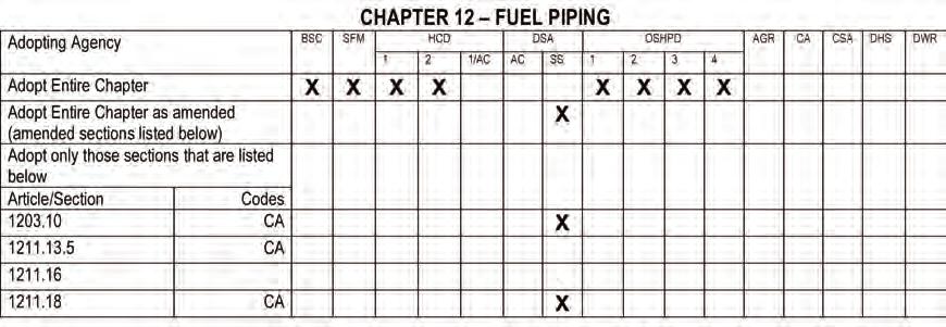
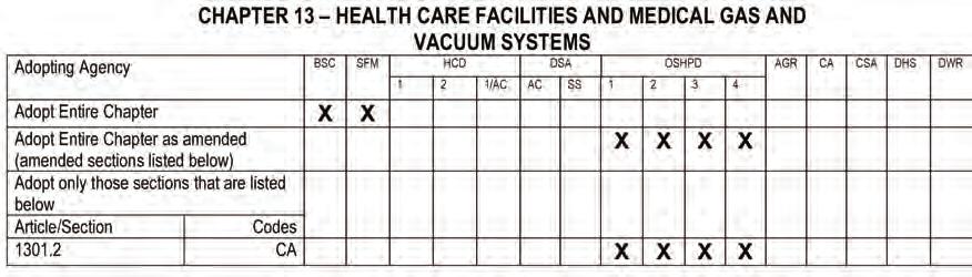
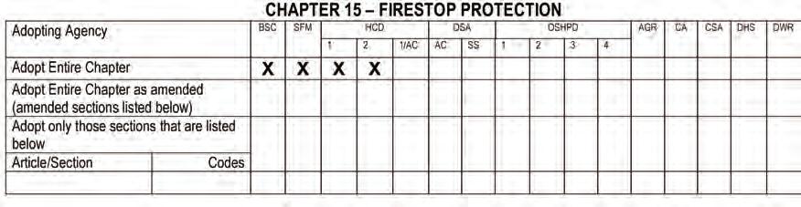
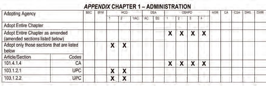
5 2007 CALIFORNIA PLUMBING CODE MATRIX ADOPTION TABLES Adopts only those section which are listed below: If there is an "X" under a particular state agency's acronym on this row, it means that particular state agency is adopting only specific model code or state-amended sections within this chapter. There will be an "X" in the column under the agency's acronym, as well as an "X" by each section that the agency has adopted. Example: SAMPLE Legend of Abbreviations of Adopting State Agencies BSC SFM HCD DSA-AC DSA SS OSHPD AGR CA CSA DHS DWR California Building Standards Commission Office of the State Fire Marshal Department of Housing and Community Development Division of the State Architect Access Compliance Division of the State Architect Structural Safety Office of Statewide Health Planning and Development Department of Food and Agriculture Department of Consumer Affairs Corrections Standards Authority Department of Health Services Department of Water Resources xiii


6 MATRIX ADOPTION TABLES 2007 CALIFORNIA PLUMBING CODE xiv

7 2007 CALIFORNIA PLUMBING CODE MATRIX ADOPTION TABLES xv


8 MATRIX ADOPTION TABLES 2007 CALIFORNIA PLUMBING CODE xvi

9 2007 CALIFORNIA PLUMBING CODE MATRIX ADOPTION TABLES xvii


10 MATRIX ADOPTION TABLES 2007 CALIFORNIA PLUMBING CODE xviii

11 2007 CALIFORNIA PLUMBING CODE MATRIX ADOPTION TABLES xix


12 MATRIX ADOPTION TABLES 2007 CALIFORNIA PLUMBING CODE xx
13 DEFINITIONS identified by volume, 30-minute retention time, baffle(s), a minimum of two compartments, a minimum total volume of 300 gallons, and gravity separation. [These interceptors comply with the requirements of Chapter 10 or are designed by a registered professional engineer.] Gravity grease interceptors are generally installed outside. Grease Interceptor A plumbing appurtenance or appliance that is installed in a sanitary drainage system to intercept nonpertroleum fats, oil, and greases (FOG) from a wastewater discharge. Grease Removal Device (GRD) Any hydromechanical grease interceptor that automatically, mechanically removes non-petroleum fats, oils and grease (FOG) from the interceptor, the control of which are either automatic or manually initiated. Grease Trap A device designed to retain grease from one (1) to a maximum of four (4) fixtures. This term has been used in previous editions of this code. Refer to Hydromechanical Grease Interceptor and Gravity Grease Interceptor, GRD, and FOG disposal system H Handwashing Fixture [For OSHPD 1, 2, 3 & 4] is a special application sink having a water supply spout mounted so the discharge point is at least 5 inches (127 mm) above the fixture rim and equipped with hot and cold supply controls not requiring direct contact of the hands for operation. The fixture can not be equipped with an aerator and wrist or elbow blade handles but may be equipped with a non-aerating laminar flow device. Sensor operated fixtures may be used, provided they are either battery operated or connected to the essential electrical system. Hangers See Supports. High Hazard See Contamination. Horizontal Branch A drain pipe extending laterally from a soil or waste stack or building drain with or without vertical sections or branches, which receives the discharge from one or more fixture drains and conducts it to the soil or waste stack or to the building drain. Horizontal Pipe Any pipe or fitting that is installed in a horizontal position or which makes an angle of less than forty-five (45) degrees with the horizontal. Hot Water Water at a temperature greater than or equal to 120 F (49 C). House Drain See Building Drain. House Sewer See Building Sewer. Hydromechanical Grease Interceptor A plumbing appurtenance or appliance that is installed in a sanitary drainage system to intercept nonpetroleum fats, oil, and grease (FOG) from a wastewater discharge and is identified by flow rate, and separation and retention efficiency. The design incorporates air entrainment, hydromechanical separation, interior baffling, and/or barriers in combination or separately, and one of the following: A External flow control, with air intake (vent): directly connected B External flow control, without air intake (vent): directly connected C Without external flow control, directly connected D Without external flow control, indirectly connected [These interceptors comply with the requirements of Table 10-2.] Hydromechanical grease interceptors are generally installed inside I Indirect Waste Pipe A pipe that does not connect directly with the drainage system but conveys liquid wastes by discharging into a plumbing fixture, interceptor, or receptacle that is directly connected to the drainage system. Individual Vent A pipe installed to vent a fixture trap and that connects with the vent system above the fixture served or terminates in the open air. Industrial Waste Any and all liquid or waterborne waste from industrial or commercial processes, except domestic sewage. Insanitary A condition that is contrary to sanitary principles or is injurious to health. Conditions to which insanitary shall apply include the following: (1) Any trap that does not maintain a proper trap seal. (2) Any opening in a drainage system, except where lawful, that is not provided with an approved water-sealed trap. (3) Any plumbing fixture or other wastedischarging receptor or device that is not supplied with water sufficient to flush and maintain the fixture or receptor in a clean condition. Exception: [HCD1 & HCD2] Non-water supplied urinals. (4) Any defective fixture, trap, pipe, or fitting. (5) Any trap, except where in this code exempted, directly connected to a drainage system, the seal of which is not protected against siphonage and back-pressure by a vent pipe. 19
14 CALIFORNIA PLUMBING CODE (6) Any connection, cross-connection, construction, or condition, temporary or permanent, that would permit or make possible by any means whatsoever for any unapproved foreign matter to enter a water distribution system used for domestic purposes. (7) The foregoing enumeration of conditions to which the term insanitary shall apply shall not preclude the application of that term to conditions that are, in fact, insanitary. Interceptor (Clarifier) A device designed and installed so as to separate and retain deleterious, hazardous, or undesirable matter from normal wastes and permit normal sewage or liquid wastes to discharge into the disposal terminal by gravity. Invert The lowest portion of the inside of a horizontal pipe J Joint, Brazed Any joint obtained by joining of metal parts with alloys that melt at temperatures higher than 840 F (449 C), but lower than the melting temperature of the parts to be joined. Joint, Soldered A joint obtained by the joining of metal parts with metallic mixtures or alloys that melt at a temperature up to and including 840 F (449 C) K No definitions L Labeled Equipment or materials bearing a label of a listing agency (accredited conformity assessment body). See Listed (third-party certified). [HCD1 & HCD2] Labeled means equipment or materials to which has been attached a label, symbol or other identifying mark of an organization, approved by the Department, that maintains a periodic inspection program of production of labeled products, installations, equipment, or materials and by whose labeling the manufacturer indicates compliance with appropriate standards or performance in a specified manner. Lavatories in Sets Two (2) or three (3) lavatories that are served by one (1) trap. Lavatory [HCD1 & HCD2] Lavatory shall mean a plumbing fixture used for washing the hands, arms, face and head. Leader An exterior vertical drainage pipe for conveying storm water from roof or gutter drains. See Downspout. Limited-density Owner-built Dwelling [HCD1] Limited-density Owner-built Dwelling shall mean any structure consisting of one or more habitable rooms intended or designed to be occupied by one family with facilities for living or sleeping, with use restricted to rural areas designated by local jurisdiction in compliance with the requirements of Health and Safety Code Section Liquid Waste The discharge from any fixture, appliance, or appurtenance in connection with a plumbing system that does not receive fecal matter. Listed [HCD 1 & HCD 2] Listed means all products that appear in a list published by an approved testing or listing agency. For additional information, see Health and Safety Code Section 17920(h). Listed (Third-party certified) Equipment or materials included in a list published by a listing agency (accredited conformity assessment body) that maintains periodic inspection on current production of listed equipment or materials and whose listing states either that the equipment or material complies with approved standards or has been tested and found suitable for use in a specified manner. Listing Agency An agency accredited by an independent and authoritative conformity assessment body to operate a material and product listing and labeling (certification) system and that is accepted by the Authority Having Jurisdiction, which is in the business of listing or labeling. The system includes initial and ongoing product testing, a periodic inspection on current production of listed (certified) products, and makes available a published report of such listing in which specific information is included that the material or product conforms to applicable standards and found safe for use in a specific manner. [HCD 1 & HCD 2] Listing Agency means an agency approved by the department that is in the business of listing and labeling products, materials, equipment, and installations tested by an approved testing agency, and that maintains a periodic inspection program on current production of listed products, equipment, and installations, and that, at least annually, makes available a published report of these listings. For additional information, see Health and Safety Code Section 17920(i). Lot A single or individual parcel or area of land legally recorded or validated by other means acceptable to the Authority Having Jurisdiction on which is situated a building or which is the site of any work regulated by this code, together with the yards, courts, and unoccupied spaces legally required for the building or works, and that is owned by or is in the lawful possession of the owner of the building or works. Low Hazard See Pollution. Low VOC Cement [HCD 1 & HCD 2] Cement with a volatile organic compound (VOC) content of less than or equal to 490 g/l for CPVC Cement, 510 g/l for PVC Cement, and 325 g/l for ABS Cement, as 20
15 DEFINITIONS determined by the South Coast Air Quality Management District s Laboratory Methods of Analysis for Enforcement Samples, Method 316A. Low VOC One-Step Cement [HCD 1 & HCD 2] Listed solvent cements that do not require the use of primer with a volatile organic compound (VOC) content of less than or equal to 490 b/l for CPVC Cement, 510 g/l for PVC Cement, and 325 g/l for ABS Cement, as determined by the South Coast Air Quality Management District s Laboratory Methods of Analysis for Enforcement Samples, Method 316A. Low VOC Primer [HCD 1 & HCD 2] Primer with a volatile organic compound (VOC) content of less than or equal to 550 g/l, as detrmined by the South Coast Air Quality Management District s Laboratory Methods of Analysis for Enforcement Samples, Method 316A M Macerating Toilet System A system comprised of a sump with macerating pump and with connections for a water closet and other plumbing fixtures, which is designed to accept, grind, and pump wastes to an approved point of discharge. Main The principal artery of any system of continuous piping to which branches may be connected. Main Sewer See Public Sewer. Main Vent The principal artery of the venting system to which vent branches may be connected. May A permissive term. Mobile Home Park Sewer That part of the horizontal piping of a drainage system that begins two (2) feet (610 mm) downstream from the last mobile home site and conveys it to a public sewer, private sewer, private sewage disposal system, or other point of disposal N Non-Water Supplied Urinal (Waterless Urinal) [HCD1 & HCD2] A plumbing fixture which does not require water supply and is designed to receive and convey the uninhibited flow of liquid waste to the gravity drainage system. Nuisance Includes, but is not limited to: (1) Any public nuisance known at common law or in equity jurisprudence. (2) Whenever any work regulated by this code is dangerous to human life or is detrimental to health and property. (3) Inadequate or unsafe water supply or sewage disposal system. [HCD 1 & HCD 2] Nuisance shall mean any nuisance as defined in Health and Safety Code Section 17920(k). Notes: 1. For applications subject to the Mobilehome Parks Act as referenced in Section of this code, refer to California Code of Regulations, Title 25, Division 1, Chapter 2 for the definition of Nuisance. 2. For applications subject to the Special Occupancy Parks Act as referenced in Section of this code, refer to California Code of Regulations, Title 25, Division 1, Chapter 2.2 for the definition of Nuisance O Offset A combination of elbows or bends in a line of piping that brings one section of the pipe out of line but into a line parallel with the other section. Oil Interceptor See Interceptor P PB Polybutylene. PE Polyethylene. PE-AL-PE Polyethylene-aluminum-polyethylene. PEX Cross-linked polyethylene. PEX-AL-PEX Cross-linked polyethylene aluminum-cross-linked polyethylene. Person A natural person, his heirs, executor, administrators, or assigns and shall also include a firm, corporation, municipal or quasi-municipal corporation, or governmental agency. Singular includes plural, male includes female. Pipe A cylindrical conduit or conductor conforming to the particular dimensions commonly known as pipe size. Plumbing The business, trade, or work having to do with the installation, removal, alteration, or repair of plumbing systems or parts thereof. Plumbing Appliance Any one of a special class of devices or equipment that is intended to perform a special plumbing function. Its operation and/or control may be dependent upon one or more energized components, such as motors, controls, heating elements, or pressure- or temperaturesensing elements. Such device or equipment may operate automatically through one or more of the following actions: a time cycle, a temperature range, a pressure range, a measured volume or weight; or the device or equipment may be manually adjusted or controlled by the user or operator. 21
16 Plumbing Appurtenance A manufactured device, a prefabricated assembly, or an on-the-job assembly of component parts that is an adjunct to the basic piping system and plumbing fixtures. An appurtenance demands no additional water supply, nor does it add any discharge load to a fixture or the drainage system. It performs some useful function in the operation, maintenance, servicing, economy, or safety of the plumbing system. Plumbing Fixture An approved-type installed receptacle, device, or appliance that is supplied with water or that receives liquid or liquid-borne wastes and discharges such wastes into the drainage system to which it may be directly or indirectly connected. Industrial or commercial tanks, vats, and similar processing equipment are not plumbing fixtures, but may be connected to or discharged into approved traps or plumbing fixtures when and as otherwise provided for elsewhere in this code. Plumbing Official See Authority Having Jurisdiction. Plumbing System Includes all potable water, building supply, and distribution pipes; all plumbing fixtures and traps; all drainage and vent pipes; and all building drains and building sewers, including their respective joints and connections, devices, receptors, and appurtenances within the property lines of the premises and shall include potable water piping, potable water treating or using equipment, medical gas and medical vacuum systems, liquid and fuel gas piping, and water heaters and vents for same. Pollution An impairment of the quality of the potable water to a degree that does not create a hazard to the public health but which does adversely and unreasonably affect the aesthetic qualities of such potable water for domestic use. Also defined as Low Hazard. Potable Water Water that is satisfactory for drinking, culinary, and domestic purposes and that meets the requirements of the Health Authority Having Jurisdiction. PP Polypropylene. Pressure The normal force exerted by a homogeneous liquid or gas, per unit of area, on the wall of the container. (1) Static Pressure The pressure existing without any flow. (2) Residual Pressure The pressure available at the fixture or water outlet after allowance is made for pressure drop due to friction loss, head, meter, and other losses in the system during maximum demand periods CALIFORNIA PLUMBING CODE Pressure-Balancing Valve A mixing valve that senses incoming hot and cold water pressures and compensates for fluctuations in either to stabilize outlet temperature. Private or Private Use Applies to plumbing fixtures in residences and apartments, to private bathrooms in hotels and hospitals, and to restrooms in commercial establishments where the fixtures are intended for the use of a family or an individual. Private Sewage Disposal System A septic tank with the effluent discharging into a subsurface disposal field, into one or more seepage pits, or into a combination of subsurface disposal field and seepage pit or of such other facilities as may be permitted under the procedures set forth elsewhere in this code. Private Sewer A building sewer that receives the discharge from more than one (1) building drain and conveys it to a public sewer, private sewage disposal system, or other point of disposal. Public or Public Use All buildings or structures that are not defined as private or private use. Public Sewer A common sewer directly controlled by public authority. PVC Poly(vinyl chloride). PVDF Polyvinylidene Fluoride Q No definitions R Receptor An approved plumbing fixture or device of such material, shape, and capacity as to adequately receive the discharge from indirect waste pipes, so constructed and located as to be readily cleaned. Regulating Equipment Includes all valves and controls used in a plumbing system that are required to be accessible or readily accessible. Relief Vent A vent, the primary function of which is to provide circulation of air between drainage and vent systems or to act as an auxiliary vent on a specially designed system. Remote Outlet When used for sizing water piping, it is the furthest outlet dimension, measuring from the meter, either the developed length of the coldwater piping or through the water heater to the furthest outlet on the hot-water piping. Rim See Flood-Level Rim. Riser A water supply pipe that extends vertically one (1) full story or more to convey water to branches or fixtures. 22
17 GENERAL REGULATIONS and fittings, manufactured in accordance with ASTM D2846, 1/2 inch through 2 inches in diameter. PVC pipe and fittings shall be cleaned and joined with primer(s) and solvent cement(s). A solvent cement transition joint between ABS and PVC building drain or building sewer shall be made using a listed transition solvent cement. [HCD 1 & HCD 2] Plastic pipe and fittings joined with solvent cement shall utilize Low-VOC primer(s), if a primer is required, and Low-VOC solvent cement(s) as defined in Section Brazing and Welding. Brazing and welding shall conform to the applicable standard(s) in Table Only brazing alloys having a liquid temperature above 1,000 F shall be used. All brazing on medical gas systems shall be performed by certified installers meeting the requirements of ANSI/ASME Boiler and Pressure Vessel Code, Section IX, Welding and Brazing Qualifications, or AWS B2.2, Standard for Brazing Procedure and Performance Qualifications [Not permitted for OSHPD 1, 2, 3 & 4] Pressure-Lock-Type Connection. This is a mechanical connection that depends on an internal retention device to prevent pipe or tubing separation. Connection is made by inserting the pipe or tubing into the fitting to a prescribed depth [Not permitted for OSHPD 1, 2, 3 & 4] Pressed Fitting. This is a mechanical connection for joining copper tubing that uses a crimping tool to affix the O-ring seal copper or copper alloy fitting to the tubing. The tubing shall be inserted into the fitting, and the crimp shall be made using the tool recommended by the manufacturer Special Joints Copper Tubing to Screw Pipe Joints. Joints from copper tubing to threaded pipe shall be made by the use of brass adapter fittings. The joint between the copper tubing and the fitting shall be a soldered brazed flared, or pressed joint and the connection between the threaded pipe and the fitting shall be made with a standard pipe size screw joint. Solder shall conform to the requirements of Section Brazed joints shall conform to the requirements of Section Flared joints shall conform to the requirements of Section Pressed joints shall conform to the requirements of Unions. Approved unions may be used in drainage piping when accessibly located in the trap seal or between a fixture and its trap in the vent system, except underground or in wet vents, at any point in the water supply system, and in gas piping as permitted by Section (4) Plastic Pipe to Other Materials. When connecting plastic pipe to other types of piping, only approved types of fittings and adapters designed for the specific transition intended shall be used Dielectric Unions. [HCD 1 & HCD 2, DSA/SS, OSHPD 1, 2, 3 & 4] Dielectric unions shall be used at all points of connection where there is a dissimilarity of metals Flanged Fixture Connections Fixture connections between drainage pipes and water closets, floor outlet service sinks and urinals shall be made by means of approved brass, hard lead, ABS, PVC, or iron flanges caulked, soldered, solvent cemented; rubber compression gaskets; or screwed to the drainage pipe. The connection shall be bolted with an approved gasket, washer, or setting compound between the fixture and the connection. The bottom of the flange shall be set on an approved firm base Closet bends or stubs shall be cut off so as to present a smooth surface even with the top of the closet ring before rough inspection is called Wall-mounted water closet fixtures shall be securely bolted to an approved carrier fitting. The connecting pipe between the carrier fitting and the fixture shall be an approved material and designed to accommodate an adequately sized gasket. Gasket material shall be neoprene, felt, or similar approved types Prohibited Joints and Connections Drainage System. Any fitting or connection that has an enlargement, chamber, or recess with a ledge, shoulder, or reduction of pipe area that offers an obstruction to flow through the drain shall be prohibited No fitting or connection that offers abnormal obstruction to flow shall be used. The enlargement of a three (3) inch (80 mm) closet bend or stub to four (4) inches (100 mm) shall not be considered an obstruction Increasers and Reducers. Where different sizes of pipes and fittings are to be connected, the proper size increasers or reducers or 33
18 CALIFORNIA PLUMBING CODE reducing fittings shall be used between the two sizes. Brass or cast-iron body cleanouts shall not be used as a reducer or adapter from cast-iron drainage pipe to iron pipe size (IPS) pipe Food-Handling Establishments. Food or drink shall not be stored, prepared, or displayed beneath soil or drain pipes, unless those areas are protected against leakage or condensation from such pipes reaching the food or drink as described below. Where building design requires that soil or drain pipes be located over such areas, the installation shall be made with the least possible number of joints and shall be installed so as to connect to the nearest adequately sized vertical stack with the provisions as follows: All openings through floors over such areas shall be sealed watertight to the floor construction Floor and shower drains installed above such areas shall be equipped with integral seepage pans All other soil or drain pipes shall be of an approved material as listed in Table 14-1 and Section All materials shall conform to established standards. Cleanouts shall be extended through the floor construction above Piping subject to operation at temperatures that will form condensation on the exterior of the pipe shall be thermally insulated Where pipes are installed in ceilings above such areas, the ceiling shall be of the removable type, or shall be provided with access panels in order to form a ready access for inspection of piping [Not permitted for OSHPD 1, 2, 3 & 4] Medical Gas and Vacuum Systems. All such piping shall be installed, tested, and verified in compliance with the appropriate consensus standards referenced in Chapter 14 and the requirements of Chapter 13. The Authority Having Jurisdiction shall require evidence of the competency of the installers and verifiers Test Gauges. Tests required by this code, which are performed utilizing dial gauges, shall be limited to gauges having the following pressure graduations or incrementations Required pressure tests of ten (10) psi (69 kpa) or less shall be performed with gauges of 1/10 pound (0.7 kpa) incrementation or less Required pressure tests exceeding ten (10) pounds (69 kpa) but less than one hundred (100) psi (689 kpa) shall be performed with gauges of one (1) psi (6.9 kpa) incrementation or less Required pressure tests exceeding one hundred (100) psi (689 kpa) shall be performed with gauges incremented for two (2) percent or less of the required test pressure Test gauges shall have a pressure range not greater than twice the test pressure applied. 34
19 CHAPTER 4 PLUMBING FIXTURES AND FIXTURE FITTINGS Note: In addition the requirements of this chapter, which provide access to, or egress from, buildings or facilities where accessibility is required for applications listed in Section 109, of the California Building Code, regulated by the Division of the State Architect Access Compliance shall also comply with Chapter 11A for public housing and Chapter 11B for public accommodations under authority cited by Gov. Code 4450 and in reference cited by Gov. Code 4450 through 4461, and H&SC , through Materials General Requirements Quality of Fixtures. Plumbing fixtures shall be constructed of dense, durable, non-absorbent materials and shall have smooth, impervious surfaces, free from unnecessary concealed fouling surfaces. Except as permitted elsewhere in this code, all fixtures shall conform in quality and design to nationally recognized applicable standards included in Table Lead. See Table Sheet lead shall be not less than the following: For safe pans not less than four (4) pounds per square foot (19.5 kg/m 2 ) or 1/16 inch (1.6 mm) thick Plumbing fixture fittings covered under the scope of NSF 61 shall comply with the requirements of NSF Water-Conserving Fixtures and Fittings Flush volumes for low-consumption and water-saver water closets and urinals shall be in accordance with applicable standards referenced in Table [HCD 1 & HCD 2] Flow rates for shower heads and faucets shall meet the requirements of this section and applicable standards referenced in Table Shower Heads [HCD 1 & HCD 2] Shower heads shall be designed and installed so that they will not exceed a water supply flow rate of 2.5 gallons (9.4 liters) per minute measured at 80 psi Faucets [HCD 1 & HCD 2] Faucets at kitchens, lavatories, wetbars, laundry sinks, or other similar use fixtures shall be designed and manufactured so that they will not exceed a water supply flow rate of 2.2 gallons (8.3 liters) per minute measured at 60 psi Water Closets. Water closets, either flush tank, flushometer tank, or flushometer valve operated, shall have an average consumption of not more than 1.6 gallons (6.1 liters) of water per flush Water Closets after January 1, 1994 [HCD 1 & HCD 2] Water closets, either flush tank, flushometer tank, or flushometer valve operated sold or installed after January 1, 1994, shall use no more than an average of 1.6 gallons (6.1 liters) of water per flush. See Health and Safety Code Section Water Closets on or after July 1, 2011 [HCD 1 & HCD 2] Water closets, either flush tank, flushometer tank, or flushometer valve operated sold or installed on or after July 1, 2011, shall have an effective flush volume in compliance with the following: (1) Single Flush Toilets - The effective flush volume shall not exceed 1.28 gallons (4.8 liters) when tested in accordance with ASME A (2) Dual Flush Toilets - The effective flush volume shall not exceed 1.28 gallons (4.8 liters) when tested in accordance with ASME A and ASME A Urinals. Urinals shall have an average water consumption of not more than 1.0 gallon (3.8 liters) of water per flush Urinals after January 1, 1994 [HCD 1 & HCD 2] Urinals and associated flushometer valves sold or installed after January 1, 1994, shall use no more than an average of one gallon (3.8 liters) per flush. See Health and Safety Code Section Urinals on or after July 1, 2011 [HCD 1 & HCD 2] Urinals and associated flushometer valves sold or installed on or after July 1, 2011, shall use no more than 0.5 gallons (1.9 liters) per flush and meet performance criteria as established in ASME A Non-Water Supplied Urinals (Waterless Urinals) [HCD 1 & HCD 2] Waterless urinals sold or installed in this state shall comply with all of the following requirements: (1) Meet performance, testing, and labeling requirements established by ASME A for vitreous china nonwater supplied urinals. (2) Be listed by an ANSI accredited third-party certification agency to ASME A (3) Follow cleaning and maintenance procedures established by the manufacturer. (4) Conform to reference standards in Table 14-1 for non-vitreous ceramic or plastic urinal fixtures. (5) Provide water distribution and fixture supply piping, sized as required elsewhere in this code, roughed-in immediately adjacent to each waterless urinal fixture installed. For additional information, see Health and Safety Code Section
20 Metered Faucets. Self-closing or self-closing metering faucets shall be installed on lavatories intended to serve the transient public, such as those in, but not limited to, service stations, train stations, airports, restaurants, and convention halls. Metered faucets shall deliver not more than 0.25 gallons (1.0 liter) of water per use Emergency Safety Showers. Emergency safety showers shall not be limited in their water supply flow rates Installation. Water-conserving fixtures shall be installed in strict accordance with the manufacturers instructions to maintain their rated performance Overflows. When any fixture is provided with an overflow, the waste shall be so arranged that the standing water in the fixture cannot rise in the overflow when the stopper is closed or remain in the overflow when the fixture is empty. The overflow pipe from a fixture shall be connected on the house or inlet side of the fixture trap, except that overflow on flush tanks may discharge into the water closets or urinals served by them, but it shall be unlawful to connect such overflows with any other part of the drainage system Strainers and Connections Strainers. All plumbing fixtures, other than water closets and urinals, shall be equipped with approved strainers having an approved waterway area. Strainers serving shower drains shall have a waterway equivalent to the area of the tailpiece Connections. Fixtures having concealed slip joint connections shall be provided with an access panel or utility space at least twelve (12) inches (305 mm) in its least dimension and so arranged without obstructions as to make such connections accessible for inspection and repair Continuous wastes and fixture tailpieces shall be constructed from the materials specified in Section for drainage piping, provided, however, that such connections where exposed or accessible may be of seamless drawn brass not less than No. 20 B&S Gauge (0.032 inches) (0.8 mm). Each such tailpiece, continuous waste, or waste and overflow shall not be less than one and one-half (1-1/2) inches (40 mm) O.D. for sinks, dishwashers, laundry tubs, bathtubs, urinals, and similar fixtures, and not less than one and one quarter (1-1/4) inches (32 mm) for lavatories, drinking fountains, and similar small fixtures Approved wye or other directional-type branch fittings shall be installed in all continuous wastes connecting or receiving the discharge from food waste disposal units, dishwashers, clothes washers, or other force discharge fixtures or 2007 CALIFORNIA PLUMBING CODE appliances. No dishwasher drain shall be connected to a sink tailpiece, continuous waste, or trap on the discharge side of a food waste disposal unit Prohibited Fixtures Water closets having an invisible seal or an unventilated space or having walls which are not thoroughly washed at each discharge shall be prohibited. Any water closet that might permit siphonage of the contents of the bowl back into the tank shall be prohibited. Drinking fountains shall not be installed in public toilet rooms Prohibited Urinals. Floor-type and wall-hung type trough urinals shall be prohibited. Urinals that have an invisible seal or that have an unventilated space or wall that is not thoroughly washed at each discharge shall be prohibited. Exception: [HCD1 & HCD2] Non-water supplied urinals Fixed wooden, or tile wash trays or sinks for domestic use shall not be installed in any building designed or used for human habitation. No sheet metal-lined wooden bathtub shall be installed or reconnected. No dry or chemical closet (toilet) shall be installed in any building used for human habitation, unless first approved by the Health Officer Special Fixtures and Specialties Water and Waste Connections. Baptisteries, ornamental and lily ponds, aquaria, ornamental fountain basins, and similar fixtures and specialties requiring water and/or waste connections shall be submitted for approval to the Authority Having Jurisdiction prior to installation Restaurant kitchen and other special use sinks may be made of approved-type bonderized and galvanized sheet steel of not less than No. 16 U.S. gauge ( inches) (1.6 mm). All sheet-metal plumbing fixtures shall be adequately designed, constructed, and braced in an approved manner to satisfactorily accomplish their intended purpose Special Use Fixtures. Special use fixtures shall be made of one of the following: (A) Soapstone (B) Chemical stoneware (C) Copper-based alloy (D) Nickel-based alloy (E) Corrosion-resistant steel (F) Other materials suited for the intended use of the fixture Zinc Alloy Components. Zinc alloy components shall meet the applicable nationally recognized standards and shall be used in accordance with their listing Drinking Fountains. [HCD1 & HCD2] Drinking fountains shall be installed and so regulated that a 38
21 PLUMBING FIXTURES AND FIXTURE FITTINGS jet of water extending at least 2 inches (51 mm) in height from the water orifice shall be constantly available. The orifice shall not be accessible to the mouth of the drinker nor subject to immersion [OSHPD 1, 2, 3 & 4, DHS] Drinking fountains shall be installed and so regulated that a jet of water extending at least 2 inches (51mm) from the water orifice shall be constantly available. The orifice shall not be accessible to the mouth of the drinker nor subject to immersion Installation Cleaning. Plumbing fixtures shall be installed in a manner to afford easy access for repairs and cleaning. Where practical, all pipes from fixtures shall be run to the nearest wall Joints. Where a fixture comes in contact with the wall or floor, the joint between the fixture and the wall or floor shall be made watertight Securing Fixtures. Floor-outlet or floormounted fixtures shall be rigidly secured to the drainage connection and to the floor, when so designed, by screws or bolts of copper, brass, or other equally corrosion-resistant material Wall-Hung Fixtures. Wall-hung fixtures shall be rigidly supported by metal supporting members so that no strain is transmitted to the connections. Flush tanks and similar appurtenances shall be secured by approved non-corrosive screws or bolts Securing Floor-Mounted, Back-Outlet Water Closet Bowls. Floor-mounted, back-outlet water closet bowls shall be set level with an angle of ninety (90) degrees (1.58 rad) between the floor and wall at the centerline of the fixture outlet. The floor and wall shall have a flat mounting surface for at least five (5) inches (127 mm) to the right and left of the fixture outlet centerline. The fixture shall be secured to the wall outlet flange or drainage connection and to the floor by corrosion-resistant screws or bolts. The closet flange shall be secured to a firm base. Where floor-mounted, back-outlet water closets are used, the soil pipe shall not be less than three (3) inches (80 mm) in diameter. Offset, eccentric, or reducing floor flanges shall not be used Setting. Fixtures shall be set level and in proper alignment with reference to adjacent walls. No water closet or bidet shall be set closer than fifteen (15) inches (381 mm) from its center to any side wall or obstruction nor closer than thirty (30) inches (762 mm) center to center to any similar fixture. The clear space in front of any water closet or bidet shall not be less than twenty-four (24) inches (610 mm). No urinal shall be set closer than twelve (12) inches (305 mm) from its center to any side wall or partition nor closer than twenty-four (24) inches (610 mm) center to center Installations for Persons with Disabilities. Where facilities for persons with disabilities are required in applicable building regulations, the facilities shall be installed in accordance with those regulations. [HCD 1/AC] For specific requirements regarding accommodations for persons with physical disabilities, see California Code of Regulations, Title 24, Part 2, Chapter 11A and/or Chapter 11B as applicable Supply Fittings. The supply lines and fittings for every plumbing fixture shall be so installed as to prevent backflow as required in Chapter Water Closets Water closet bowls for public use shall be of the elongated type. In nurseries, schools, and other similar places where plumbing fixtures are provided for the use of children under six (6) years of age, water closets shall be of a size and height suitable for children s use. All water closets shall be equipped with seats as required below Water Closet Seats Water closet seats shall be of smooth, non-absorbent material All water closet seats, except those within dwelling units, shall be either of the open front type or have an automatic seat cover dispenser Water closet seats shall be properly sized for the water closet bowl type Seats for use in public buildings shall conform to the standard listed in Table Urinals. Every water supply to a urinal shall be protected by an approved-type vacuum breaker or other approved backflow prevention device as described in Section Flushing Devices for Water Closets and Urinals Flushing Devices Required. Each water closet, urinal, clinic sink, or other plumbing fixture that depends on trap siphonage to discharge its waste contents shall be provided with a flushometer valve, flushometer tank, or flush tank designed and installed so as to supply water in sufficient quantity and rate of flow to flush the contents of the fixture to which it is connected, to cleanse the fixture, and to refill the fixture trap, without excessive water use. Flushing devices shall meet anti-siphon requirements required in Chapter Automatic Flushing Tanks. Tanks flushing more than one (1) urinal shall be automatic in operation and of sufficient capacity to provide the 39
22 necessary volume to flush and properly cleanse all urinals simultaneously. Automatically controlled flushometer valves may be substituted for flush tanks Flushometer Valves. No manually controlled flushometer valve shall be used to flush more than one (1) urinal, and each such urinal flushometer valve shall be an approved, self-closing type discharging a predetermined quantity of water. Flushometers shall be installed so that they will be accessible for repair. Flushometer valves shall not be used where the water pressure is insufficient to properly operate them. When the valve is operated, it shall complete the cycle of operation automatically, opening fully and closing positively under the line water pressure. Each flushometer shall be provided with a means for regulating the flow through it Water Supply for Flush Tanks. An adequate quantity of water shall be provided to flush and clean the fixture served. The water supply for flushing tanks and flushometer tanks equipped for manual flushing shall be controlled by a float valve or other automatic device designed to refill the tank after each discharge and to completely shut off the water flow to the tank when the tank is filled to operational capacity. Provision shall be made to automatically supply water to the fixture so as to refill the trap seal after each flushing. The water supply to flush tanks equipped for automatic flushing shall be controlled by a suitable timing device Overflows in Flush Tanks. Flush tanks shall be provided with overflows discharging into the water closet or urinal connected thereto. Overflows supplied as original parts with the fixture shall be of sufficient size to prevent tank flooding at the maximum rate at which the tank is supplied with water under normal operating conditions and when installed per manufacturer s instructions Floor Drains and Shower Stalls Floor drains shall be considered plumbing fixtures, and each such drain shall be provided with an approved-type strainer having a waterway equivalent to the area of the tailpiece. Floor drains, floor receptors, and shower drains shall be of an approved type, suitably flanged to provide a watertight joint in the floor Location of Floor Drains. Floor drains shall be installed in the following areas: Toilet rooms containing two (2) or more water closets or a combination of one (1) water closet and one (1) urinal, except in a dwelling unit Commercial kitchens Laundry rooms in commercial buildings and common laundry facilities in multi-family dwelling buildings Food Storage Areas. If drains are provided in storerooms, walk-in freezers, walk-in coolers, refrigerated equipment, or other locations where food 2007 CALIFORNIA PLUMBING CODE is stored, such drains shall have indirect waste piping. Separate waste pipes shall be run from each food storage area, each with an indirect connection to the building sanitary drainage system. Traps shall be provided if required under Section of this code and shall be vented. Indirect drains may be located in freezers or other spaces where freezing temperatures are maintained, provided that traps, when supplied, are located where the seal will not freeze. Otherwise, the floor of the freezer shall be sloped to a floor drain located outside of the storage compartment Floor Slope. Floors shall be sloped to floor drains Shower receptors are plumbing fixtures and shall conform to the general requirements contained in Section Each such shower receptor shall be constructed of vitrified china or earthenware, ceramic tile, porcelain-enameled metal, or of such other material as may be acceptable to the Authority Having Jurisdiction. No shower receptor shall be installed unless it conforms to acceptable standards as referenced in Table 14-1 or until a specification or a prototype or both of such receptor has first been submitted to and approval obtained from the Authority Having Jurisdiction Each shower receptor shall be an approved type and be so constructed as to have a finished dam, curb, or threshold that is at least one (1) inch (25.4 mm) lower than the sides and back of such receptor. In no case shall any dam or threshold be less than two (2) inches (51 mm) or more than nine (9) inches (229 mm) in depth when measured from the top of the dam or threshold to the top of the drain. Each such receptor shall be provided with an integral nailing flange to be located where the receptor meets the vertical surface of the finished interior of the shower compartment. The flange shall be watertight and extend vertically a minimum of one (1) inch (25.4 mm) above the top of the sides of the receptor. The finished floor of the receptor shall slope uniformly from the sides toward the drain not less than one-quarter (1/4) inch per foot (20.9 mm/m), nor more than one-half (1/2) inch per foot (41.8 mm/m). Thresholds shall be of sufficient width to accommodate a minimum twenty-two (22) inch (559 mm) door. Shower doors shall open so as to maintain a minimum twenty-two (22) inch (559 mm) unobstructed opening for egress. Exception: Showers that are designed to comply with the accessibility standards listed in Table [HCD 1/AC] Specific requirements regarding accommodations for persons with physical disabilities are contained in California Code of Regulations, Title 24, Part 2, Chapter 11A and/or Chapter 11B as applicable. Table 14-1 does not contain the correct accessibility standards for use in California All shower compartments, regardless of shape, shall have a minimum finished interior of one thousand twenty-four (1,024) square inches (0.66 m 2 ) 40
23 PLUMBING FIXTURES AND FIXTURE FITTINGS and shall also be capable of encompassing a thirty (30) inch (750 mm) circle. The minimum required area and dimensions shall be measured at a height equal to the top of the threshold and at a point tangent to its centerline. The minimum area and dimensions shall be maintained to a point seventy (70) inches (1778 mm) above the shower drain outlet with no protrusions other than the fixture valve or valves, shower head, soap dishes, shelves, and safety grab bars or rails. Fold-down seats in accessible shower stalls shall be permitted to protrude into the thirty (30) inch (750 mm) circle. Exception No. 1: Showers that are designed to comply with Chapter 11A or 11B of the California Building Code. Exception No. 2: The minimum required area and dimension shall not apply where an existing bathtub is replaced by a shower receptor having minimum overall dimensions of 30 inches (750 mm) in width and 60 inches (1,500 mm) in length. Exception No. 3: [HCD 1/AC] Specific requirements regarding accommodations for persons with physical disabilities are contained in California Code of Regulations, Title 24, Part 2, Chapter 11A and/or Chapter 11B as applicable. ICC/ANSI A117.1 does not contain the correct accessibility standards for use in California When the construction of on-site built-up shower receptors is permitted by the Authority Having Jurisdiction, one of the following means shall be employed: (1) Shower receptors built directly on the ground: Shower receptors built directly on the ground shall be watertight and shall be constructed from approved-type dense, nonabsorbent and noncorrosive materials. Each such receptor shall be adequately reinforced, shall be provided with an approved flanged floor drain designed to make a watertight joint in the floor, and shall have smooth, impervious, and durable surfaces. (2) Shower receptors built aboveground: When shower receptors are built aboveground, the subfloor and rough side of walls to a height of not less than three (3) inches (76 mm) above the top of the finished dam or threshold shall be first lined with sheet plastic,* lead,* or copper,* or shall be lined with other durable and watertight materials. All lining materials shall be pitched onequarter (1/4) inch per foot (20.9 mm/m) to weep holes in the subdrain of a smooth and solidly formed subbase. All such lining materials shall extend upward on the rough jambs of the shower opening to a point no less than three (3) inches (76 mm) above the top of the finished dam or threshold and shall extend outward over the top of the rough threshold and be turned over and fastened on the outside face of both the rough threshold and the jambs. Nonmetallic shower subpans or linings may be built up on the job site of not less than three (3) layers of standard, grade fifteen (15) pound (6.8 kg) asphalt-impregnated roofing felt. The bottom layer shall be fitted to the formed subbase and each succeeding layer thoroughly hot-mopped to that below. All corners shall be carefully fitted and shall be made strong and watertight by folding or lapping, and each corner shall be reinforced with suitable webbing hot-mopped in place. All folds, laps, and reinforcing webbing shall extend at least four (4) inches (102 mm) in all directions from the corner, and all webbing shall be of approved type and mesh, producing a tensile strength of not less than fifty (50) psi (344.5 kpa) in either direction. Nonmetallic shower subpans or linings may also consist of multilayers of other approved equivalent materials suitably reinforced and carefully fitted in place on the job site as elsewhere required in this section. Linings shall be properly recessed and fastened to approved backing so as not to occupy the space required for the wall covering and shall not be nailed or perforated at any point that may be less than one (1) inch (25.4 mm) above the finished dam or threshold. An approved-type subdrain shall be installed with every shower subpan or lining. Each such subdrain shall be of the type that sets flush with the subbase and shall be equipped with a clamping ring or other device to make a tight connection between the lining and the drain. The subdrain shall have weep holes into the waste line. The weep holes located in the subdrain clamping ring shall be protected from clogging. All shower lining materials shall conform to approved standards acceptable to the Authority Having Jurisdiction. *Lead and copper subpans or linings shall be insulated from all conducting substances other than their connecting drain by fifteen (15) pound (6.8 kg) asphalt felt or its equivalent, and no lead pan or liner shall be constructed of material weighing less than four (4) pounds per square foot (19.5 kg/m 2 ). Copper pans or liners shall be at least No. 24 B & S Gauge (0.02 inches) (0.5 mm). Joints in lead pans or liners shall be burned. Joints in copper pans or liners shall be soldered or brazed. Plastic pans shall not be coated with asphalt-based materials Tests for Shower Receptors. Shower receptors shall be tested for watertightness by filling with water to the level of the rough 41
24 threshold. The test plug shall be so placed that both upper and under sides of the subpan shall be subjected to the test at the point where it is clamped to the drain Floors of public shower rooms shall have a nonskid surface and shall be drained in such a manner that wastewater from one bather will not pass over areas occupied by other bathers. Gutters in public or gang shower rooms shall have rounded corners for easy cleaning and shall be sloped not less than two (2) percent toward drains. Drains in gutters shall be spaced not more than eight (8) feet (2438 mm) from sidewalls nor more than sixteen (16) feet (4879 mm) apart Location of Valves and Heads. Control valves and showerheads shall be located on the sidewall of shower compartments or be otherwise arranged so that the showerhead does not discharge directly at the entrance to the compartment and the bather can adjust the valves prior to stepping into the shower spray Water Supply Riser. Every water supply riser from the shower valve to the showerhead outlet, whether exposed or not, shall be securely attached to the structure Minimum Number of Required Fixtures Fixture Count. Plumbing fixtures shall be provided for the type of building occupancy and in the minimum number shown in Table [DSA-AC] Effective January 1, 1990, in new construction and those existing facilities which occupancy type are listed in Tables 4-1 and 4-4 for public use, which apply for permit to undertake construction, structural alterations, repairs or improvement which exceed 50 percent of the square footage of the entire facility, shall install water closets, urinals, lavatories and drinking fountains as stipulated in Tables 4-1 and 4-4 for public use. Community and/or municipal parks with a bleacher capacity not exceeding 500 seats shall be exempt from the requirements of this section and Tables 4-1 and 4-4. Each bathroom shall comply with Part 2, Chapters 11A and 11B of the California Building Code Access to Fixtures In multi-story buildings, accessibility to the required fixtures shall not exceed one (1) vertical story Fixtures accessible only to private offices shall not be counted to determine compliance with this section Separate Facilities. Separate toilet facilities shall be provided for each sex. Exceptions: (1) Residential installations CALIFORNIA PLUMBING CODE (2) In occupancies serving ten (10) or fewer people, one (1) toilet facility, designed for use by no more than one (1) person at a time, shall be permitted for use by both sexes. (3) In business and mercantile occupancies with a total floor area of fifteen hundred (1500) square feet (139.5 m 2 ) or less, one (1) toilet facility, designed for use by no more than one (1) person at a time, shall satisfy the requirements for serving customers and employees of both sexes [For OSHPD 1, 2, 3 & 4] Separate toilet facilities shall be provided for the use of patients, staff personnel and visitors Fixture Requirements for Special Occupancies Additional fixtures may be required when unusual environmental conditions or special activities are encountered In food preparation areas, fixture requirements may be dictated by health codes Types of occupancy not shown in Table 4-1 shall be considered individually by the Authority Having Jurisdiction Facilities in Mercantile and Business Occupancies Serving Customers Requirements for customers and employees shall be permitted to be met with a single set of restrooms accessible to both groups. The required number of fixtures shall be the greater of the required number for employees or the required number for customers Fixtures for customer use shall be permitted to be met by providing a centrally located facility accessible to several stores. The maximum distance from entry to any store to this facility shall not exceed five hundred (500) feet (152.4 m) In stores with a floor area of one hundred fifty (150) square feet (13.9 m 2 ) or less, the requirement to provide facilities for employees shall be permitted to be met by providing a centrally located facility accessible to several stores. The maximum distance from entry to any store to this facility shall not exceed three hundred (300) feet (91.4 m) Food Service Establishments. Food service establishments with an occupant load of one hundred (100) or more shall be provided with separate facilities for employees and customers. Customer and employee facilities may be combined for occupant loads less than one hundred (100) [DHS] Employee Lavatories in Food Establishments. Employee lavatories installed in food establishments shall be equipped with an approved 42
25 PLUMBING FIXTURES AND FIXTURE FITTINGS single spout capable of providing tempered (100 F 115 F) (37.8 C 46.1 C) running water. Exception: This requirement applies only to commissaries serving mobile food preparation units Toilet Facilities for Workers. Suitable toilet facilities shall be provided and maintained in a sanitary condition for the use of workers during construction [CA] Cosmetology. Each school shall provide public toilet rooms for each sex on the licensed premises in accordance with the California Plumbing Code, Table [CA] Cosmetology Establishments. Each establishment where hairdressing services are performed shall provide at least one public toilet room located on the premises in accordance with the California Plumbing Code, Table [DHS] Commissaries Serving Mobile Food Preparation Units. Commissaries serving mobile food preparation units shall have at least one hose bib. The hose bib shall be supplied with hot and cold water and be provided with a single spout, a backflow-preventer device and shall be located on the premises of the establishment Fixtures and Fixture Fittings for Persons with Disabilities. Plumbing fixtures and fixture fittings for persons with disabilities shall conform to the appropriate standards referenced in Table 14-1 of this code. [HCD 1/AC] Specific requirements regarding accommodations for persons with physical disabilities are contained in California Code of Regulations, Title 24, Part 2, Chapter 11A and/or Chapter 11B as applicable. Table 14-1 does not contain the correct accessibility standards for use in California Limitation of Hot Water Temperature for Public Lavatories. Hot water delivered from public-use lavatories shall be limited to a maximum temperature of 120 F. The water heater thermostat shall not be considered a control for meeting this provision Bathtubs and Whirlpool Bathtubs. Unless otherwise listed, all bathtubs and whirlpool bathtubs shall comply with the following requirements: A removable panel shall be provided to access and remove the pump. Whirlpool pump access located in the crawl space shall be located no more than twenty (20) feet (6096 mm) from an access door, trap door, or crawl hole The circulation pump shall be located above the crown weir of the trap The pump and the circulation piping shall be self-draining to minimize water retention in accordance with standards referenced in Table Suction fittings on whirlpool bathtubs shall comply with the listed standards Limitation of Hot Water in Bathtubs and Whirlpool Bathtubs. The maximum hot water temperature discharging from the bathtub and whirlpool bathtub filler shall be limited to 120 F. The water heater thermostat shall not be considered a control for meeting this provision Installation of Fixture Fittings. Where two separate handles control the hot and cold water, the left-hand control of the faucet when facing the fixture fitting outlet shall provide the means to alter the hot water temperature from the fixture fitting. Single-handle mixing valves shall have the flow of hot water correspond to the markings on the fitting Bidets Materials. Bidets shall conform to the standards listed in Table Backflow Protection. The water supply to the bidet shall be protected according to Chapter 6, which allows for an airgap or vacuum breaker Future Fixtures. When provision is made for the future installation of fixtures, those provided for shall be considered in determining the required sizes of drain pipes. Construction for future installations shall be terminated with a plugged fitting or fittings. Where the plugged fitting is at the point where the trap of a fixture may be installed, the plumbing system for such fixture shall be complete and conform with all plumbing requirements of this code Shower and Tub-Shower Combination Control Valves. Showers and tub-shower combinations in all buildings shall be provided with individual control valves of the pressure balance, thermostatic, or combination pressure balance/thermostatic mixing valve type that provide scald and thermal shock protection. These valves shall conform to ASSE Gang showers, when supplied with a single temperature-controlled water supply pipe, may be controlled by a master thermostatic mixing valve in lieu of individually controlled pressure balance, thermostatic, or combination pressure balance/thermostatic mixing valves. Handle position stops shall be provided on such valves and shall be adjusted per the manufacturer s instructions to deliver a maximum mixed water setting of 120 F (49 C). The water heater thermostat shall not be considered a suitable control for meeting this provision. 43
26 Table CALIFORNIA PLUMBING CODE TABLE 4-1 Minimum Plumbing Facilities 1 Each building shall be provided with sanitary facilities, including provisions for persons with disabilities as prescribed by the Department Having Jurisdiction 19. For requirements for persons with disabilities, Chapter 11A or 11B of the California Building Code, shall be used. The minimum number of fixtures shall be calculated at fifty (50) percent male and fifty (50) percent female based on the total occupant load. The occupant load and use of the building or space under consideration shall first be established using the Occupant Load Factor Table A. Once the occupant load and uses are determined, the requirements of Section and Table 4-1 shall be applied to determine the minimum number of plumbing fixtures required. This table applies to new buildings, additions to a building, changes of occupancy or type in an existing building resulting in increased occupant load (example: change an assembly room from fixed seating to open seating). Exception: New cafeterias for employee use are the only use exempted from this requirement. Exceptions: (1) [HCD 1/AC & HCD 2] For applications listed in Sections and regulated by the Department of Housing and Community Development, each building shall be provided with sanitary facilities, including provisions for persons with disabilities as prescribed by the Department. Covered multifamily dwellings required to be accessible to persons with disabilities shall comply with California Code of Regulations, Title 24, Part 2, Chapter 11A. Permanent buildings in mobilehome parks and special occupancy parks required to be accessible by persons with disabilities, shall comply with California Code of Regulations, Title 24, Part 2, Chapter 11B. (2) [HCD 1] For limited density owner-built rural dwelling sanitary facilities, the type, design and number of facilities as required and approved by the local health official shall be provided to the dwelling sites. It shall not be required that such facilities be located within the dwelling. Type of Building Water Closets 14 Urinals 5, 10 Lavatories Bathtubs or Showers 3, 13, 18 Drinking Fountains or Occupancy 2 (Fixtures per Person) (Fixtures per Person) (Fixtures per Person) (Fixtures per Person) (Fixtures per Person) Assembly places Male Female Male Male Female theatres, auditoriums, 1: : : per 40 1 per 40 convention halls, etc. 2: : : for permanent 3: : Add one fixture employee use Over 55, add 1 fixture for each for each additional 40 additional 50 males. persons. Assembly places Male Female Male Male Female theatres, auditoriums, 1: : : : : : convention Halls, etc. 2: : : : : : for public use 3: : : : : : : : Over 750, add one fixture Over 750, add one fixture Over 400, add one fixture Over 600, add 1 fixture for each additional 500 for each additional 500 for each additional 500 for each additional persons. persons. males and 1 for each 300 males. additional 125 females. Dormitories 9 Male Female Male Male Female 1 per 8 1 per School or labor 17 1 per 10 1 per 8 1 per 25 1 per 12 1 per 12 For females, add Add 1 fixture for each Over 150, add 1 fixture Over 12, add one fixture for 1 bathtub per 30. additional 25 males (over for each additional 50 each additional 20 males Over 150, add 1 10) and 1 for each additional males. and 1 for each 15 bathtub per females (over 8). additional females. Dormitories Male Female Male Male Female 1 per 8 for staff use 17 1: : per 50 1 per 40 1 per 40 2: : : : Over 55, add 1 fixture for each additional 40 persons. Dwellings 4 Single dwelling 1 per dwelling 1 per dwelling 1 per dwelling Multiple dwelling or 1 per dwelling or 1 per dwelling or 1 per dwelling or apartment house 17 apartment unit apartment unit apartment unit Hospital waiting rooms 1 per room 1 per room 1 per Hospitals Male Female Male Male Female for employee use 1: : : per 40 1 per 40 2: : : : : Add one fixture for each Over 55, add 1 fixture for additional 50 males. each additional 40 persons. Hospitals Individual room 1 per room 1 per room 1 per room Ward room 1 per 8 patients 1 per 10 patients 1 per 20 patients 1 per Industrial 6 warehouses, Male Female Up to 100, 1 per 10 1 shower for 1 per workshops, foundries, 1: : 1-10 persons each 15 persons and similar 2: : exposed to establishments 3: : Over 100, 1 per 15 excessive heat or for employee use 4: : persons 7, 8 to skin contam- 5: : ination with poison- Over 100, add 1 fixture for ous, infectious, or each additional 30 persons. irritating material Institutional other than Male Female Male Male Female 1 per 8 1 per hospitals or penal 1 per 25 1 per 20 0: per 10 1 per 10 institutions (on each 1: occupied floor) Add one fixture for each additional 50 males. 44
27 PLUMBING FIXTURES AND FIXTURE FITTINGS Table A Table A. Occupant Load Factor: Occupancy*, ** Occupant Load Factor (square feet) (CBC 2001, Table A-29A) Group A 1. Auditoriums, convention halls, dance floors, 15 lodge rooms, stadiums, and casinos (where no fixed seating is provided) (use 1/2 one-half the number of fixed seating) 2. Conference rooms, dining rooms, drinking establishments, exhibit rooms, gymnasiums, 30 lounges, stages, and similar uses, including restaurants classified as Group B occupancies 3. Worship places; principal assembly area, educational and activity unit 30 (use 1/2 one-half the number of fixed seating) (where no fixed seating is provided) Group B Office or public buildings (area accessible to 200 the public) Group E Schools for daycare, elementary, secondary 50 Educational Facilities Other than Group E Colleges, universities, adult centers, etc. 50 Group F Workshops, foundries and similar establishments 2,000 Group H Hazardous materials fabrication and storage 2,000 Group I Hospital general use area, health care facilities 200 Group M Retail or Wholesale stores 200 Group R Congregate residence, Group R Group S Warehouse 5,000 * Any uses not specifically listed shall be based on similar uses listed in this table. ** For building or space with mixed occupancies, use appropriate occupancy group for each area (for example, a school may have an A occupancy for the gymnasium, a B occupancy for the office, an E occupancy for the classrooms, etc.) Accessory areas may be excluded (for example: hallway, restroom, stair enclosure) 47
28 Table CALIFORNIA PLUMBING CODE TABLE 4-2 [For OSHPD 1, 2, 3 & 4] Minimum Plumbing Facilities Space Handwashing Scrub Toilets Bathtubs Service Clinic Fixture Sinks or Sinks 1 Sinks Showers OSHPD 1 General Acute Care Hospitals 1, 20 and 1, 20 Acute Psychiatric Hospitals Administration Space Lobby Male Female Airborne infection isolation rooms Cardiac Catheterization Procedure room Staff clothing changing areas shower Central Sterile Supply 1 15 Cesarean/delivery Service Space Labor Rooms Recovery Room 1 1 Drug distribution station 1 Cesarean operating room 2 10 Delivery room 1 10 Staff clothing changing areas Male Female Staff lounge toilet 1 1 LDR or LDRP room Waiting room Clinical Laboratory Service Space 11 1 Dietetic Service Space 1 Toilets and lockers 1 Emergency Service Standby emergency medical service Lobby - public toilets 1 1 Treatment room 1 Open plan 1:4 cubicles Patient toilet 1 1 Administrative center/nurses' station 1 Basic emergency medical service Public waiting 1 Treatment areas, more than Treatment room 1 Open plan 1:4 cubicles Observation units 1:4 cubicles 1:8 cubicles Emergency surgery, Cystoscopy, or Special procedure room Employee dressing rooms Male Female Exam and treatment rooms 1 Housekeeping room 1 Intensive Care Units 7 1 Open plan 1:3 beds Patient rooms 28 1 Staff lounge Newborn Intensive Care Unit (NICU) 1:4 bassinets 17 1 Control station 1 Staff lounge Laboratories Laundry Soiled linen 1 Medicine preparation rooms or station 1 48
29 PLUMBING FIXTURES AND FIXTURE FITTINGS Table 4-2 Cont. Morgue and Autopsy 1 1 Nourishment station or center 1 2 Nuclear medicine Procedure room 1 Mold room 1 Radiotherapy Reception/waiting area Nursing service space Administrative center or nurse station 1 1 Examination or treatment room 1 Patient room 1 Patient toilet and bath facilities :4 beds 1:12 16 Multi-purpose rooms 1 2 Central bathing facility 1 Staff toilet room Medicine preparation room 1 Nourishment area 1 Nurses' stations 9 or administration center 1 Nurseries Well Newborn 1:6 bassinets Exam/Workrooms 1 Outpatient service space 1 Outpatient surgery 1 Endoscopy examination room 1 Pediatric and Adolescent Unit Patient room 1 1 Play areas toilet room 1 1 Central bathing toilet room 1 1 Pharmacy Postanesthesia care units (PACU) 1 1 Protective environment room Psychiatric Nursing Unit Patient room 1 Patient toilet and bath facilities :12 16 Radiological/Imaging Services Space 1 Computerized tomography (CT) Ultrasound Angiography Flouroscopy Patient toilet Staff toilets Rehabilitation Therapy Space Patient Waiting area Male toilet room Female toilet room Training toilet 1 Physical therapy service space 1 Occupational therapy service space 1 Speech pathology 1 Renal Dialysis Service Space 1:4 stations 1 Bloodborne Infection Isolation Room 1 Nurses' station 1 Medication dispensing 1 Home training room 1 Repair room 1 1 Patient toilet 1 1 Staff lounge shower Waiting room toilet 1 1 Surgical Service Space 2 3 Staff clothing change areas Male shower Female shower Clean-up rooms 1 Substerile area 1 Anesthesia workroom 1 8 Soiled workroom or soiled holding 1 1 Utility Room 49
30 Table 4-2 Cont CALIFORNIA PLUMBING CODE Clean 27 1 Soiled OSHPD 2 Skilled Nursing or Intermediate Care Facilities Nurses' Station 1 Utility room 1 Clean 1 21 Soiled Patient beds 1:8 2 1:6 1:20 Administration space - public toilets 1 Employee lockers Male Female Outpatient waiting room toilet room Laundry 1 Dietetic service space Kitchen 1 Food serving area 1 Employee washroom 1 Airborne infection isolation room Protective environment room Medicine rooms Optional services 1 15 Physical therapy 1 1 Occupational therapy 1 1 Speech pathology/audiology 1 Housekeeping room 1 1 OSHPD 3 Licensed Clinics and any freestanding building under a hospital license where outpatient clinical services are provided Examination and treatment rooms 1 Primary care clinic 1 Utility room 1 15 Birthing Clinic 1 1 Clean-up room 1 Birthing room toilet room Shower 1 Housekeeping room 1 Surgery Clinic Clean-up room 1 Outpatient changing Postanesthesia recovery 1 Housekeeping room 1 Nurses' control area 1 Staff clothing area Male 1 1 Female 1 1 Chronic Dialysis 1 Nurse station 1:8 patients Patient toilet room Staff lockers Bloodborne infection isolation room Utility room 1 1 Home training 1 Rehabilitation Clinics Physical therapy space 1 Occupational therapy 1 Speech pathology/audiology Housekeeping room 1 OSHPD 4 24 Correctional Treatment Centers 1 Nurses' station 1 Utility Room 1 Clean
31 PLUMBING FIXTURES AND FIXTURE FITTINGS Table 4-2 Cont. Soiled 1 22 Patients beds 1:8 2 1:6 1:12 Employee dressing rooms Male Female Outpatient services 1 Airborne infection isolation room Protective environment room Medicine rooms Treatment and Exam Rooms 1 Toilets Patient 13 1:8 2 1:6 1:12 Staff Employee dressing rooms and lockers Male Female Outpatient services Waiting area Housekeeping room 1 Soiled utility room 1 Pharmacy 1 1 Each department or nursing unit shall be served by a housekeeping room equipped with a service sink. Departments may share service closets provided the departmental services are compatible. The fixtures listed cannot be shared. 2 Conventional spouts and controls on hot-and cold-water supplies are acceptable. Aerators are not permitted. Non-aerating laminar flow devices are permitted. Nourishment stations shall have a handwashing fixture in or immediately accessible from the nourishment area. 3 A minimum of two scrub sinks shall be provided in a surgical unit containing one operating room. Four scrub sinks shall be provided in surgical units containing two operating rooms. One additional scrub sink shall be provided per each additional operating room. 4 The scrub sink is in addition to the required number for surgeries. 5 The following fixtures shall be provided in airborne infection or protective environment rooms of hospitals only: a. Within an adjoining toilet room, a handwashing fixture, a shower containing a seat or a space for a shower chair, and water closet equipped with bedpan flushing attachment with a vacuum breaker. b. A handwashing fixture within a separate anteroom. Exception: 1. Chemical dependency recovery hospitals. 2. In emergency department, separate toilet/shower not required. 6 The following fixtures shall be provided in isolation rooms of correctional treatment centers only: a. Within an adjoining toilet area, a handwashing fixture, a shower containing a seat or a space for a shower chair, and water closet equipped with bedpan flushing attachment with a vacuum breaker. b. A handwashing fixture within a separate anteroom. 7 Includes burn center spaces and acute respiratory-care service spaces, coronary-care service spaces. 8 A toilet room with handwashing fixture shall adjoin each fluoroscopy room. 9 One toilet with lavatory and one shower may serve two labor rooms. 10 One additional scrub sink per cesarean or delivery operating room. 11 Provide emergency eye-wash and shower. 12 Handwashing fixtures shall be located in convenient locations throughout the space. 13 Fixtures serving individual patient rooms shall not be considered as meeting the required ratios for bedrooms not served by individual adjoining toilet or bathrooms. 14 The clinic sink may be deleted if all bedrooms in the nursing unit are provided with adjoining toilets with bedpan flushing devices. 15 Conventional controls on hot-and cold-water supplies are acceptable. The water discharge points shall be 5 inches (127 millimeters) above the fixture rims. Aerators are not permitted. Non-aerating laminar flow devices are permitted. 16 A minimum of one bathtub is required on each floor of an acute care or acute psychiatric hospital providing skilled nursing or intermediate care services. 17 In a multiple-bed room, every bed position shall be within 20 feet (6 meters) of a hands-free handwashing fixture. Where an individual room concept is used, a handwashing fixture shall be provided within each infant care room. 18 When three or more procedure rooms are provided. 19 If a separate medicine room is provided, the room shall be equipped with a sink in addition to the nurses' station handwashing fixture. Hot-water supplies are optional. 20 Chemical dependency recovery hospitals are only required to provide handwashing fixtures for exam rooms and kitchens. All other fixtures may be equipped per Footnote Handwashing fixtures may be deleted if room is storage and holding only. 22 Handwashing fixtures may be deleted if room is temporary holding of soiled materials. 23 Toilet shall be equipped with a bedpan flushing attachment. 24 Optional services approved by the licensing agency shall comply with the applicable space requirements of OSHPD 1 and Shall be provided in each separate room where open medication is handled. 26 Conveniently accessible throughout the unit. 27 Includes rooms or areas within coronary and intensive-care units and postanethesia recovery rooms. 28 Modular toilet/sink combination units located within a privacy curtain may be used within each patient space or private room. 29 Toilet room facilities located adjacent to or in the immediate vicinity are adequate. 51
32 Table 4-3 Table CALIFORNIA PLUMBING CODE TABLE 4-3 Urinals (Trough urinal Drinking Water Closets to individual Fountains Type of Building (Fixtures per Person) urinal equivalence) Lavatories (Fixtures Bathtubs or Showers (Fixtures or Occupancy Male Female Male per Person) Fixtures per Person) 7 per Person) 3 Nonindustrial office Length of Number of :10 persons per shift buildings, public trough urinal individual required to shower buildings and similar urinals establishments " (610 mm) " (914 mm) " (1219 mm) additional for 1 additional for 60" (1524 mm)...3 each additional 4 each additional 40 72" (1879 mm)...4 employees or fraction employees or fraction thereof thereof Industrial factories, " (610 mm) to 100 1:10 persons per shift warehouses, loft " (914 mm)...2 employees required to shower buildings and similar " (1219 mm) per 10 establishments " (1524 mm) " (1829 mm)...4 Over employees 1 additional for 1 additional for each additional 40 each additional 15 employees or fraction employees or fraction thereof thereof 1 The figures shown are based on one fixture being the minimum required for the number of persons indicated or any fraction thereof. 2 Each water closet shall occupy a separate compartment which shall be equipped with a door, door latch and clothes hook. The door and the walls or partitions between fixtures shall be sufficient to assure privacy. 3 Drinking fountains shall not be located in toilet rooms. 4 Washing facilities shall be reasonably accessible to all employees. 5 Toilet facilities shall be accessible to the employees at all times. Where practicable, toilet facilities should be within 200 feet (61 m) of locations at which workers are regularly employed and should not be more than one floor-to-floor flight of stairs from working areas. 6 Urinals may be installed instead of water closets in toilet rooms to be used only by men provided that the number of water closets shall not be less than two thirds of the minimum number of toilet facilities specified. The length of trough urinals to the equivalent number of individual urinals shall be based on the above table. 7 When there are less than five employees, separate toilet rooms for each sex are not required provided toilet rooms can be locked from the inside and contain at least one water closet. 8 Twenty-four linear inches of wash sink or 18 inches of circular basin, when provided with water outlets for such space, shall be considered equivalent to one lavatory. Exception: The requirements of Table 4-3 do not apply to mobile crews or to normally unattended work locations provided employees at these locations have immediately available transportation to nearby toilet facilities which meet the requirements of Table 4-3. Type of Building Water Closets Urinals Lavatories Bathtubs or Showers Drinking Fountains or Occupancy 2 (Fixtures per Person) (Fixtures per Male) (Fixtures per Person) (Fixtures per Person) (Fixtures per Person) Day Use Male Female May be substituted for Public Beaches 1, up to two-thirds of the No sex designated water closets required Minimum of 2 Picnic Areas Male Female TABLE 4-4 Overnight Use campsites 3 May be substituted for campsites 4 Public Beaches campsites 3 up to one-third of the water closets required 3 Organized Camps Minimum 1 per camp 1Toilets shall be located in accordance with actual use patterns on the beach. The reasonable intent of the toilet requirements is that it should apply on the basis of average daily use during periods of peak use. The health officer may determine how many days the population standard may be exceeded. 2Laundry facilities are not required, but if they are provided, must be a minimum of two laundry trays or a washing machine. 3Toilet facilities shall not be farther than 400 feet from any lot or campsite. 4Showers are not required, but it provided, they shall be provided on the indicated ratio. Outdoor rinse-off showers may be cold water only. 5Toilets shall be located within 300 feet from the living accommodations they serve. 6Showers shall be provided in the living area or in a centrally located structure. Exception: Intermittent short-term organized camps are not required to provide shower facilities, but it provided, they shall comply with this part. 52
33 WATER SUPPLY AND DISTRIBUTION bibb-type vacuum breaker, or by an atmospheric vacuum breaker installed at least six (6) inches (152 mm) above the highest point of usage located on the discharge side of the last valve. In climates where freezing temperatures occur, a listed self-draining frost-proof hose bibb with an integral backflow preventer or vacuum breaker shall be used Water-cooled compressors, degreasers, or any other water-cooled equipment shall be protected by a backflow preventer installed in accordance with the requirements of this chapter. Note: Water-cooled equipment that produces backpressure shall be equipped with the appropriate protection Water inlets to water-supplied aspirators shall be equipped with a vacuum breaker installed in accordance with its listing requirements and this chapter. The discharge shall drain through an airgap. When the tailpiece of a fixture to receive the discharge of an aspirator is used, the airgap shall be located above the flood-level rim of the fixture Potable water makeup connections to steam or hot water boilers shall be provided with a listed backflow protection assembly Nonpotable Water Piping. In cases where it is impractical to correct individual cross-connections on the domestic waterline, the line supplying such outlets shall be considered a nonpotable water line. No drinking or domestic water outlets shall be connected to the nonpotable waterline. Whenever possible, all portions of the nonpotable waterline shall be exposed, and all exposed portions shall be properly identified in a manner satisfactory to the Authority Having Jurisdiction. Each outlet on the nonpotable waterline that may be used for drinking or domestic purposes shall be posted: CAUTION: NONPOTABLE WATER, DO NOT DRINK. [HCD 1 & HCD 2] An internationl symbol of a glass in a circle with a slash through it shall be provided similar to that provided in Figure Potable water supply to carbonators shall be protected by either an airgap or a vented backflow preventer for carbonated beverage dispensers installed within the carbonated beverage dispenser. The carbonated beverage dispenser shall bear the label of an approved testing agency, certifying and attesting that such equipment has been tested and inspected and meets the requirements of the approved applicable standard. Carbonated beverage dispensers without an approved internal airgap or vented backflow preventer for carbonated beverage dispensers and carbonated beverage dispensing systems shall have the water supply protected with a vented backflow preventer for carbonated beverage dispensers Water Treatment Units. Reverse osmosis drinking water treatment units shall meet the requirements of the appropriate standards referenced in Table Waste or discharge from reverse osmosis or other types of water treatment units shall enter the drainage system through an airgap Backflow preventers shall not be located in any area containing fumes that are toxic, poisonous, or corrosive Deck-mounted or equipment-mounted vacuum breakers shall be installed in accordance with their listing and the manufacturers instructions, with the critical level not less than one (1) inch (25.4 mm) above the flood-level rim Protection from Fire Systems. Note: Fire Protection Systems has not been adopted by the State Fire Marshal. This section cannot be adopted or enforced pursuant to California Health and Safety Code (a), which is being cited for reference. California Health and Safety Code (a) For the purposes of this section the following are definitions of class I and class II systems; (1) American Water Works Association (A.W.W.A) Manual No. M-14 class 1 Automatic fire sprinkler systems with direct connection from public water mains only; no pumps, tanks, or reservoirs; no physical connection from other water supplies; no antifreeze or additives of any kind; and all sprinkler drains discharging to the atmosphere or other safe outlets. (2) American Water Works Association (A.W.W.A) Manual No. M-14 class 2 Automatic fire sprinkler systems which are the same as class 1, except that booster pumps may be installed in the connections from the street mains. (b) Automatic fire sprinkler systems described in subdivision (a) shall not required any backflow protection equipment at the service connection other than required by standards for those systems contained in the publication of the National Fire Protection Association entitled Installation of Sprinkler Systems (NFPA Pamphlet No. 13, 1980 edition) Except as provided under Sections and , potable 115
34 Table CALIFORNIA PLUMBING CODE 1, 2, 3 TABLE 6-4 Material Water Distribution Building Supply Pipe Pipe and Fittings and Fittings Hot Cold Asbestos Cement X Brass X X X Copper X X X Cast Iron X X X CPVC X X X Galvanized Malleable Iron X X X Galvanized Wrought Iron X X X Galvanized Steel X X X PE X PE-AL-PE X X X PEX 1, 2, 3 X X X PEX-AL-PEX 1 X X X PVC X 1 [BSC, DSA/SS & HCD] The use of PEX-AL-PEX in potable water supply systems is not adopted. 2 [For BSC, DSA/SS, HCD, AGR and DHS] When PEX tubing is placed in soil and is used in potable water systems intended to supply drinking water to fixtures or appliances, the tubing or piping shall be sleeved with a material approved for potable water use in soil or other material that is impermeable to solvents or petroleum products. 3 [For BSC, DSA/SS, HCD, AGR, and DHS] Pex tubing shall meet the requirements of NSF P171 CL-R, ASTM F or an equivalent or more stringent standard when used in continuously recirculating hot water systems where chlorinated water is supplied to the system and the PEX tubing is exposed to the hot water 100% of the time. water supplies to fire protection systems that are normally under pressure, including but not limited to standpipes and automatic sprinkler systems, except in one- or twofamily residential sprinkler systems, piped in materials approved for potable water distribution systems shall be protected from back-pressure and back-siphonage by one of the following testable devices: (1) Double check valve assembly (2) Double check detector assembly (3) Reduced pressure backflow preventer (4) Reduced pressure detector assembly Potable water supplies to fire protection systems that are not normally under pressure shall be protected from backflow and shall meet the requirements of the appropriate standards referenced in Table Where fire protection systems supplied from a potable water system include a fire department (siamese) connection that is located less than seventeen hundred (1,700) feet (518.2 m) from a nonpotable water source that could be used by the fire department as a secondary water supply, the potable water supply shall be protected by one of the following: (1) Reduced pressure backflow preventor (2) Reduced pressure detector assembly Note: Nonpotable water sources include fire department vehicles carrying water of questionable quality or water that is treated with antifreeze, corrosion inhibitors, or extinguishing agents Where antifreeze, corrosion inhibitors, or other chemicals are added to a fire protection system supplied from a potable water supply, the potable water system shall be protected by one of the following: (1) Reduced pressure backflow preventer (2) Reduced pressure detector assembly Whenever a backflow device is installed in the potable water supply to a fire protection system, the hydraulic design of the system shall account for the pressure drop through the backflow device. If such devices are retrofitted for an existing fire protection system, the hydraulics of the sprinkler system design shall be checked to verify that there will be sufficient water pressure available for satisfactory operation of the fire sprinklers Residential Sprinkler Systems. When residential sprinkler systems are installed using the potable water system, they shall be installed in accordance with the standards listed in Table Special Equipment, Water Supply Protection. Vacuum breakers for washer-hose bedpans shall be located not less than five (5) feet (1,524 mm) above the floor. Hose connections in health care or laboratory areas shall not be less than six (6) feet (1,829 mm) above the floor. 116
35 WATER SUPPLY AND DISTRIBUTION Portable cleaning equipment, dental vacuum pumps, and chemical dispensers shall be protected from backflow by an airgap, an atmospheric vacuum breaker, a spill-proof vacuum breaker, or a reduced pressure principle backflow preventer Water Heater Connectors. Flexible metallic water heater connectors or reinforced flexible water heater connectors connecting water heaters to the piping system shall be in compliance with the appropriate standards listed in Table Combination stop-and-waste valves or cocks shall not be installed underground Pure Water Process Systems. The water supply to a pure water process system, such as dialysis water systems, semiconductor washing systems, and similar process piping systems, shall be protected from back-pressure and back-siphonage by a reduced-pressure principle backflow preventer Dialysis Water Systems. The individual connections of the dialysis related equipment to the dialysis pure water system do not require additional backflow protection Plumbing Fixture Fittings. Plumbing fixture fittings with integral backflow protection shall comply with ASME A Materials All pipe, tube, and fittings carrying water used in potable water systems intended to supply drinking water shall meet the requirements of NSF 61 as found in Table All materials used in the water supply system, except valves and similar devices, shall be of a like material, except where otherwise approved by the Authority Having Jurisdiction. Materials for building water piping and building supply piping shall be in accordance with Table 6-4 and the standards in Table Exceptions: (1) [OSHPD 1, 2, 3 & 4] Use of CPVC is not permitted for applications under authority of the Office of Statewide Health Planning and Development. (2) [OSHPD 1, 2, 3 & 4] Installation and use of PEX tubing shall be in accordance with manufacturer s installation standards. PEX piping shall not be used for any application that would result in noncompliance with any provisions of the California Building Standards Code. (3) [OSHPD 1, 2, 3 & 4] Use of PEX-AL-PEX piping is not permitted for applications under the authority of the Office of Statewide Health Planning and Development. (4) [For OSHPD 1, 2, 3 & 4] When PEX tubing is placed in soil and is used in potable water systems intended to supply drinking water to fixtures or appliances, the tubing or piping shall be sleeved with a material approved for potable water use in soil or other material that is impermeable to solvents or petroleum products. (5) [For OSHPD 1, 2, 3 & 4] PEX tubing shall meet the requirements of NSF P171 CL-R, ASTM F or an equivalent or more stringent standard when used in continuously recirculating hot water systems where chlorinated water is supplied to the system and the PEX tubing is exposed to the hot water 100% of the time Local Authority to Approve CPVC Pipe Within Residential Buildings Under Specified Conditions [HCD1 & HCD2] The local responsible building official of any city, county, or city and county, shall authorize by permit the use of CPVC for hot and cold water distribution systems within the interior of residential buildings provided all of the following conditions are satisfied: (a) Permit Conditions. Any building permit issued pursuant to Section shall be conditioned on compliance with the mitigation measures set forth in this section. (b) Approved Materials. Only CPVC plumbing material listed as an approved material and installed in accordance with this code may be used. (c) Installation and Use. Any installation and use of CPVC plumbing material pursuant to this section shall comply with all applicable requirements of this code and Section 1.2 of Appendix I of this code, Installation Standard for CPVC Solvent Cemented Hot and Cold Water Distribution Systems, IAPMO IS (d) Certification of Compliance. Prior to issuing a building permit pursuant to Section , the building official shall require as part of the permitting process that the contractor, or the appropriate plumbing subcontractors, provide written certification: (1) that is required in subdivision (e), and (2) that he or she will comply with the flushing procedures and worker safety measures set forth in Section 1.2 of Appendix I of this code, Installation Standard for CPVC Solvent Cemented Hot and Cold Water Distribution Systems, IAPMO IS (e) Worker Safety. Any contractor applying for a building permit that includes the use of CPVC plumbing materials authorized pursuant to this section shall include in the permit application a signed written certification stating that: 117
36 CALIFORNIA PLUMBING CODE (1) They are aware of the health and safety hazards associated with CPVC plumbing installations; (2) They have included in their Injury and Illness Prevention Plan the hazards associated with CPVC plumbing pipe installations; and (3) The worker safety training elements of their Injury and Illness Prevention Plan meet the Department of Industrial Relation s guidelines. (f) Findings of Compliance. The building official shall not give final permit approval of any CPVC plumbing materials installed pursuant to Section unless he or she finds that the material has been installed in compliance with the requirements of this code and that the installer has complied with the requirements in Section of Appendix I of this code, Installation Standards for CPVC Solvent Cemented Hot and Cold Water Distribution Systems, IAPMO IS (g) Penalties. Any contractor or subcontractor found to have failed to comply with the ventilation, glove or flushing requirements of Section of Appendix I of this code, Installation Standards for CPVC Solvent Cemented Hot and Cold Water Distribution Systems, IAPMO IS shall be subject to the penalties in Health and Safety Code, Division 13, Part 1.5, Chapter 6 (Section et. seq.). In addition, if during the conduct of any building inspection the building official finds that the ventilation and glove requirements of Section of Appendix I of this code, Special Requirements for CPVC Installation within Residential Buildings, are being violated, such building officials shall cite the contractor or subcontractor for that violation Copper tube for water piping shall have a weight of not less than Type L. Exception: Type M copper tubing may be used for water piping when piping is aboveground in, or on, a building or underground outside of structures All hard-drawn copper tubing for water supply and distribution in addition to the required incised marking, shall be marked in accordance with ASTM B 88 Seamless Copper Water Tube as listed in Table The colors shall be: Type K, green; Type L, blue; Type M, red Listed flexible copper water connectors shall be installed in readily accessible locations, unless otherwise listed Cast-iron fittings up to and including two (2) inches (51 mm) in size, when used in connection with potable water piping, shall be galvanized All malleable iron water fittings shall be galvanized Piping and tubing that has previously been used for any purpose other than for potable water systems shall not be used Approved plastic materials may be used in water service piping, provided that where metal water service piping is used for electrical grounding purposes, replacement piping therefore shall be of like materials. Exception: Where a grounding system acceptable to the Authority Having Jurisdiction is installed, inspected, and approved, metallic pipe may be replaced with nonmetallic pipe Solder shall conform to the requirements of Section Water pipe and fittings with a lead content which exceeds eight (8) percent shall be prohibited in piping systems used to convey potable water. Note: On or after January 1, 2010, see Section of the Health and Safety Code for the lead content of pipes, pipe or plumbing fittings, or fixtures intended to convey or dispense water for human consumption PEX. Cross-linked polyethylene (PEX) tubing shall be marked with the appropriate standard designation(s) listed in Table 14-1 for which the tubing has been approved. PEX tubing shall be installed in compliance with the provisions of this section. [For OSHPD 1, 2, 3, & 4] Installation and use of PEX tubing shall be in accordance with manufacturer s standards. PEX piping shall not be used for any application that would result in noncompliance with any provisions of the California Building Standards Code PEX Fittings. Metal insert fittings, metal compression fittings, and cold expansion fittings used with PEX tubing shall be manufactured to and marked in accordance with the standards for the fittings in Table [For OSHPD 1, 2, 3, & 4] Installation and use of PEX tubing shall be in accordance with manufacturer s standards. PEX piping shall not be used for any application that would result in noncompliance with any provisions of the California Building Standards Code Water Heater Connections. PEX tubing shall not be installed within the first eighteen (18) inches (457 mm) of piping connected to a water heater Flexible Corrugated Connectors. Flexible corrugated connectors of copper or stainless steel shall be limited to the following connector lengths: Water Heater Connectors twenty-four (24) inches (609 mm). Fixture Connectors thirty (30) inches (762 mm). Washing Machine Connectors seventy-two (72) inches (1827 mm). Dishwasher and Icemaker Connectors one hundred twenty (120) inches (3048 mm). 118
37 WATER SUPPLY AND DISTRIBUTION PEX-AL-PEX and PE-AL-PE. Crosslinked polyethylene-aluminum-crosslinked polyethylene (PEX-AL-PEX) and polyethylene-aluminumpolyethylene (PE-AL-PE) composite pipe shall be marked with the appropriate standard designations listed in Table 14-1 for which the piping has been listed or approved. PEX-AL-PEX and PE-AL-PE piping shall be installed in compliance with the provisions of this section. [HCD 1 & HCD 2, BSC, DSA SS] PEX-AL-PEX is not adopted for use in potable water supply and distribution systems. Exception: [OSHPD 1, 2, 3 & 4] Use of PEX-AL- PEX piping is not permitted for applications under the authority of the Office of Statewide Health Planning and Development PEX-AL-PEX and PE-AL-PE. Fittings used with PEX-AL-PEX and PE-AL-PE piping shall be manufactured to and marked in accordance with the standard for the fittings in Table [HCD 1 & HCD 2, BSC, DSA SS] PEX-AL-PEX is not adopted for use in potable water supply and distribution systems. Exception: [OSHPD 1, 2, 3 & 4] Use of PEX-AL- PEX piping is not permitted for applications under the authority of the Office of Statewide Health Planning and Development Water Heater Connections. PEX-AL- PEX or PE-AL-PE tubing shall not be installed within the first eighteen inches (18) (457 mm) of piping connected to a water heater. [HCD 1 & HCD 2, BSC, DSA SS] PEX-AL-PEX is not adopted for use in potable water supply and distribution systems. Exception: [OSHPD 1, 2, 3 & 4] Use of PEX-AL- PEX piping is not permitted for applications under the authority of the Office of Statewide Health Planning and Development Water Heater Connectors. Flexible metallic water heater connectors or reinforced flexible water heater connectors connecting water heating to the piping system shall be in compliance with the appropriate standards listed in Table Valves Valves up to and including two (2) inches (51 mm) in size shall be brass or other approved material. Sizes over two (2) inches (51 mm) may have cast-iron or brass bodies. Each gate or ball valve shall be a fullway type with working parts of noncorrosive material A fullway valve controlling all outlets shall be installed on the discharge side of each water meter and on each unmetered water supply. Water piping supplying more than one building on any one premises shall be equipped with a separate fullway valve to each building, so arranged that the water supply can be turned on or off to any individual or separate building provided; however, that supply piping to a singlefamily residence and building accessory thereto may be controlled on one valve. Such shutoff valves shall be accessible at all times. A fullway valve shall be installed on the discharge piping from water supply tanks at or near the tank. A fullway valve shall be installed on the cold water supply pipe to each water heater at or near the water heater In multidwelling units, one (1) or more shutoff valves shall be provided in each dwelling unit so that the water supply to any plumbing fixture or group of fixtures in that dwelling unit can be shut off without stopping water supply to fixtures in other dwelling units. These valves shall be accessible in the dwelling unit that they control All valves used to control two (2) or more openings shall be fullway gate valves, ball valves, or other approved valves designed and approved for the service intended A control valve shall be installed immediately ahead of each water-supplied appliance and immediately ahead of each slip joint or appliance supply. Parallel water distribution systems shall provide a control valve either immediately ahead of each fixture being supplied or installed at the manifold and shall be identified with the fixture being supplied All required shutoff or control valves shall be accessible A single control valve shall be installed on a water supply line ahead of any automatic metering valve that supplies a battery of fixtures [For OSHPD 1, 2, 3, & 4] Each riser or branch shall be provided with an accessible sectionalizing valve in hot-and cold-water systems to permit servicing or replacement of piping or equipment. Stop valves shall be provided at each fixture Joints and Connections Types of Joints Flared Joints. Flared joints for soft copper water tubing shall be made with fittings meeting approved standards. The tubing shall be reamed to the full bore, resized to round, and expanded with a proper flaring tool Mechanical Joints. Mechanical joints for cast-iron water pipe shall conform to nationally recognized standards. 119
38 CALIFORNIA PLUMBING CODE Mechanically Formed Tee Fittings. Mechanically extracted collars shall be formed in a continuous operation consisting of drilling a pilot hole and drawing out the tube surface to form a collar having a height not less than three (3) times the thickness of the branch tube wall. The branch tube shall be notched to conform with the inner curve of the run tube and shall have two (2) dimple/depth stops to ensure that penetration of the branch tube into the collar is of sufficient depth for brazing and that the branch tube does not obstruct the flow in the main line tube. Dimple/depth stops shall be in line with the run of the tube. The second dimple shall be one quarter (1/4) inch (6.35 mm) above the first and shall serve as a visual point of inspection. All joints shall be brazed in accordance with Section Soldered joints shall not be allowed Use of Joints Copper Water Tube. Joints in copper tubing shall be made by the appropriate use of approved fittings properly soldered or brazed together as provided in Section or or by means of approved flared or compression fittings in Section or Solder and soldering flux shall conform to the requirements of Section Mechanically formed tee fittings shall be made by brazing only and shall conform to the requirements of Section Plastic Fittings. Female PVC screwed fittings for water piping shall be used with plastic male fittings and plastic male threads only Slip Joints. In water piping, slip joints may be used only on the exposed fixture supply PVC Pipe [For DSA/SS, OSHPD 1, 2, 3 & 4] Joints in PVC pipe shall be made as provided in Section , UPC Gravity Supply Tanks. Gravity tanks for potable water shall be tightly covered, and have not less than a sixteen (16) squareinch (10,323 mm 2 ) overflow screened with copper screen having not less than fourteen (14) nor more than eighteen (18) openings per linear inch (25.4 mm). allowing for friction and other pressure losses, a tank and a pump or other means that will provide said fifteen (15) pound (103.4 kpa) pressure shall be installed. Whenever fixtures and/or fixture fittings are installed that require residual pressure higher than fifteen (15) pounds per square inch (103.4 kpa), that minimum residual pressure shall be provided Excessive Water Pressure. Where static water pressure in the water supply piping is in excess of eighty (80) pounds per square inch (552 kpa), an approved-type pressure regulator preceded by an adequate strainer shall be installed and the static pressure reduced to eighty (80) pounds per square inch (552 kpa) or less. Such regulator(s) shall control the pressure to all water outlets in the building unless otherwise approved by the Authority Having Jurisdiction. Each such regulator and strainer shall be accessibly located aboveground or in a vault equipped with a properly sized and sloped bore-sighted drain to daylight, shall be protected from freezing, and shall have the strainer readily accessible for cleaning without removing the regulator or strainer body or disconnecting the supply piping. All pipe size determinations shall be based on eighty (80) percent of the reduced pressure when using Table Any water system provided with a check valve, backflow preventer, or any other normally closed device that prevents dissipation of building pressure back into the water main shall be provided with an approved, listed, and adequately sized expansion tank or other approved device having a similar function to control thermal expansion. Such expansion tank or other approved device shall be installed on the building side of the check valve, backflow preventer, or other device and shall be sized and installed in accordance with the manufacturer s recommendation. Any water system containing storage water Sizing Method Example Using TABLE 6-7 Public Use Fixtures LAV LAV UR UR WC WC LAV LAV UR UR WC WC F E D C B A Water Pressure, Pressure Regulators, Pressure Relief Valves, and Vacuum Relief Valves Inadequate Water Pressure. Whenever the water pressure in the main or other source of supply will not provide a residual water pressure of at least fifteen (15) pounds per square inch (103.4 kpa), after G H I J K L T M LAV UR WC LAV UR WC S R Q P O N 120
39 CHAPTER 10 TRAPS AND INTERCEPTORS Traps Required Each plumbing fixture, excepting those having integral traps or as permitted in Section , shall be separately trapped by an approved type of waterseal trap. Not more than one (1) trap shall be permitted on a trap arm One (1) trap may serve a set of not more than three (3) single compartment sinks or laundry tubs of the same depth or three (3) lavatories immediately adjacent to each other and in the same room if the waste outlets are not more than thirty (30) inches (762 mm) apart and the trap is centrally located when three (3) compartments are installed No food waste disposal unit shall be installed with any set of restaurant, commercial, or industrial sinks served by a single trap; each such food waste disposal unit shall be connected to a separate trap. Each domestic clothes washer and each laundry tub shall be connected to a separate and independent trap, except that a trap serving a laundry tub may also receive the waste from a clothes washer set adjacent thereto. No clothes washer or laundry tub shall be connected to any trap for a kitchen sink The vertical distance between a fixture outlet and the trap weir shall be as short as practicable, but in no case shall the tailpiece from any fixture exceed twenty-four (24) inches (610 mm) in length Traps Protected by Vent Pipes Each plumbing fixture trap, except as otherwise provided in this code, shall be protected against siphonage and back-pressure, and air circulation shall be assured throughout all parts of the drainage system by means of a vent pipe installed in accordance with the requirements of this code Each fixture trap shall have a protecting vent so located that the developed length of the trap arm from the trap weir to the inner edge of the vent shall be within the distance given in Table 10-1, but in no case less than two (2) times the diameter of the trap arm A trap arm may change direction without the use of a cleanout when such change of direction does not exceed ninety (90) degrees (1.6 rad). All horizontal changes in direction of trap arms shall comply with Section Exception: For trap arms three (3) inches (80 mm) in diameter and larger, the change of direction shall not exceed one hundred and thirty-five (135) degrees (2.36 rad) without the use of a cleanout The vent pipe opening from a soil or waste pipe, except for water closets and similar fixtures, shall not be below the weir of the trap. TABLE 10-1 Horizontal Distance of Trap Arms (Except for water closets and similar fixtures)* Distance Distance Trap Arm Trap to Vent Trap Arm Trap to Vent Inches Feet Inches mm mm 1-1/ / & larger & larger 3048 Slope one-fourth (1/4) inch per foot (20.9 mm/m) *The developed length between the trap of a water closet or similar fixture (measured from the top of the closet ring [closet flange] to the inner edge of the vent) and its vent shall not exceed six (6) feet (1829 mm) Traps Described Each trap, except for traps within an interceptor or similar device, shall be self-cleaning. Traps for bathtubs, showers, lavatories, sinks, laundry tubs, floor drains, urinals, drinking fountains, dental units, and similar fixtures shall be of standard design and weight and shall be of ABS, cast brass, cast iron, lead, PP, PVC, or other approved material. An exposed and readily accessible drawn-brass tubing trap, not less than 17 B&S Gauge (0.045 inch) (1.1 mm), may be used on fixtures discharging domestic sewage. Exceptions: (1) Drawn-brass tubing traps shall not be used for urinals. Each trap shall have the manufacturer's name stamped legibly in the metal of the trap, and each tubing trap shall have the gauge of the tubing in addition to the manufacturer's name. Every trap shall have a smooth and uniform interior waterway. (2) [HCD1 & HCD2] Non-water supplied urinals conforming to ASME A or reference standards in Table 14-1 for nonvitreous ceramic or plastic urinal fixtures No more than one (1) approved slip joint fitting may be used on the outlet side of a trap, and no tubing trap shall be installed without a listed tubing trap adapter. Listed plastic trap adapters may be used to connect listed metal tubing traps. 151
40 CALIFORNIA PLUMBING CODE The size (nominal diameter) of a trap for a given fixture shall be sufficient to drain the fixture rapidly, but in no case less than nor more than one (1) pipe size larger than given in Table 7-3. The trap shall be the same size as the trap arm to which it is connected Traps Prohibited. No form of trap that depends for its seal upon the action of movable parts shall be used. No trap that has concealed interior partitions, except those of plastic, glass, or similar corrosion-resisting material, shall be used. "S" traps, bell traps, and crown-vented traps shall be prohibited. No fixture shall be double trapped. Drum and bottle traps shall be installed only for special conditions. No trap shall be installed without a vent, except as otherwise provided in this code Trap Seals. Each fixture trap shall have a water seal of not less than two (2) inches (51 mm) and not more than four (4) inches (102 mm), except where a deeper seal is found necessary by the Authority Having Jurisdiction. Traps shall be set true with respect to their water seals and, where necessary, they shall be protected from freezing. Exception: [HCD1 & HCD2] Non-water supplied urinals conforming to ASME A or reference standards in Table 14-1 for non-vitreous ceramic or plastic urinal fixtures Floor Drain Traps. Floor drains shall connect into a trap so constructed that it can be readily cleaned and of a size to serve efficiently the purpose for which it is intended. The drain inlet shall be so located that it is at all times in full view. When subject to reverse flow of sewage or liquid waste, such drains shall be equipped with an approved backwater valve Trap Seal Protection. Floor drain or similar traps directly connected to the drainage system and subject to infrequent use shall be protected with a trap seal primer, except where not deemed necessary for safety or sanitation by the Authority Having Jurisdiction. Trap seal primers shall be accessible for maintenance Building Traps. Building traps shall not be installed except where required by the Authority Having Jurisdiction. Each building trap when installed shall be provided with a cleanout and with a relieving vent or fresh-air intake on the inlet side of the trap, which need not be larger than one-half the diameter of the drain to which it connects. Such relieving vent or fresh-air intake shall be carried above grade and terminate in a screened outlet located outside the building Industrial Interceptors (Clarifiers) and Separators When Required. Interceptors (clarifiers) (including grease, oil, sand interceptors [clarifiers], etc.) shall be required by the Authority Having Jurisdiction when they are necessary for the proper handling of liquid wastes containing grease, flammable wastes, sand, solids, acid or alkaline substances, or other ingredients harmful to the building drainage system, the public or private sewer, or to public or private sewage disposal Approval. The size, type, and location of each interceptor (clarifier) or separator shall be approved by the Authority Having Jurisdiction. Except where otherwise specifically permitted, no wastes other than those requiring treatment or separation shall be discharged into any interceptor (clarifier) Design. Interceptors (clarifiers) for sand and similar heavy solids shall be so designed and located as to be readily accessible for cleaning and shall have a water seal of not less than six (6) inches (152 mm) Relief Vent. Interceptors (clarifiers) shall be so designed that they will not become air-bound if closed covers are used. Each interceptor (clarifier) shall be properly vented Location. Each interceptor (clarifier) cover shall be readily accessible for servicing and maintaining the interceptor (clarifier) in working and operating condition. The use of ladders or the removal of bulky equipment in order to service interceptors (clarifiers) shall constitute a violation of accessibility. Location of all interceptors (clarifiers) shall be shown on the approved building plan Maintenance of Interceptors. Interceptors shall be maintained in efficient operating condition by periodic removal of accumulated grease, scum, oil, or other floating substances and solids deposited in the interceptor Discharge. The waste pipe from oil and sand interceptors shall discharge as approved by the Authority Having Jurisdiction Slaughterhouses, Packing Establishments, etc. Every fish, fowl, and animal slaughterhouse or establishment; every fish, fowl, and meat packing or curing establishment; every soap factory, tallowrendering, fat-rendering, and hide-curing establishment shall be connected to and shall drain or discharge into an approved grease interceptor (clarifier). 152
41 FUEL PIPING Interconnections for Standby Fuels. Where supplementary gas for standby use is connected downstream from a meter or a service regulator where a meter is not provided, a device to prevent backflow shall be installed. [NFPA 54: ] A three-way valve installed to admit the standby supply and at the same time shut off the regular supply shall be permitted to be used for this purpose. [NFPA 54: ] Required Gas Supply The following regulations, as set forth in this section and in Section , Required Gas Piping Size, shall be the standard for the installation of gas piping. All natural gas regulations and tables are based on the use of gas having a specific gravity of sixty hundredths (0.60), supplied at six (6) to eight (8) inches ( mm) water column pressure at the outlet of the meter. For undiluted liquefied petroleum gas, gas piping may be sized for 2,500 Btu per cubic foot (25.9 Watt-hours/L) at eleven (11) inches (279 mm) water column and specific gravity of one and fifty-two hundredths (1.52). Note: Where gas of a different specific gravity is to be delivered, the serving gas supplier should be contacted for specific gravity conversion factors to use in sizing piping systems from the pipe sizing tables in this chapter The hourly volume of gas required at each piping outlet shall be taken as not less than the maximum hourly rating as specified by the manufacturer of the appliance or appliances to be connected to each such outlet Where the gas appliances to be installed have not been definitely specified, Table 12-1 may be used as a reference to estimate requirements of typical appliances. To obtain the cubic feet per hour (L/sec.) of gas required, divide input of appliances by the average Btu (Watt-hour) heating value per cubic foot (L) of the gas. The average Btu (Watt-hour) per cubic foot (L) of the gas in the area of the installation may be obtained from the serving gas supplier The size of the supply piping outlet for any gas appliance shall not be less than one-half (1/2) inch (15 mm). The minimum size of any piping outlet for a mobile home shall be three-quarter (3/4) inch (20 mm) Required Gas Piping Size Where the maximum demand does not exceed two hundred fifty (250) cubic feet per hour (2 L/sec.) and the maximum length of piping between the meter and the most distant outlet is not over two hundred fifty (250) feet (76,200 mm), the size of each section and each outlet of any system of gas piping shall be determined by means of Table 12-7 for steel pipe, or Table for copper tubing systems, or Table for CSST systems. Other Systems within the range of Table 12-7 or or Table may be sized from that table or by means of the methods set forth in Section To determine the size of each section of pipe in any system within the range of Table 12-7, proceed as follows: (1) Measure the length of the pipe from the gas meter location to the most remote outlet on the system. (2) In Table 12-7 select the length in feet column and row showing that distance, or the next longer distance if the table does not give the exact length. (3) Starting at the most remote outlet, find in the row just selected the gas demand for that outlet. If the exact figure of demand is not shown, choose the next larger figure in the row. (4) At the top of this column will be found the correct size of pipe. (5) Using this same row, proceed in a similar manner for each section of pipe serving this outlet. For each section of pipe, determine the total gas demand supplied by that section. Where gas piping sections serve both heating and cooling equipment and the installation prevents both units from operating simultaneously, only the larger of the two demand loads needs be used in sizing these sections. (6) Size each section of branch piping not previously sized by measuring the distance from the gas meter location to the most remote outlet in that branch and follow the procedures of steps 2, 3, 4, and 5 above. Note: Size branch piping in the order of their distance from the meter location, beginning with the most distant outlet not previously sized For conditions other than those covered by Section , such as longer runs or greater gas demands, the size of each gas piping system shall be determined by standard engineering methods acceptable to the Authority Having Jurisdiction, and each such system shall be so designed that the total 191
42 CALIFORNIA PLUMBING CODE pressure drop between the meter or other point of supply and any outlet when full demand is being supplied to all outlets, will at no time exceed fivetenths (0.5) inches (12.7 mm) water column pressure Where the gas pressure may be higher than fourteen (14) inches (356 mm) or lower than six (6) inches (152 mm) of water column, or when diversity demand factors are used, the design, pipe, sizing, materials, location, and use of such systems first shall be approved by the Authority Having Jurisdiction. Piping systems designed for pressures higher than the serving gas supplier's standard delivery pressure shall have prior verification from the gas supplier of the availability of the design pressure. Systems using undiluted liquefied petroleum gas may be sized using Table for steel pipe and Table for CSST for eleven (11) inches (279 mm) of water column and in accordance with the provisions of Sections and For copper tubing systems using undiluted liquefied petroleum gas, the capacity of the tubing shall be determined by multiplying the values of Table by the appropriate factor from Table Figure 12-2 Example Illustrating Use of Tables 12-1 and 12-7 Problem: Determine the required pipe size of each section and outlet of the piping system shown in Figure Gas to be used has a specific gravity of sixty hundredths (0.60) and eleven hundred (1,100) Btu per cubic foot (11.4 Watthour/L), delivered at eight (8) inch (203 mm) water column pressure. Solution: (1) Maximum gas demand of outlet A 32 cubic feet per hour (0.21 L/sec.) (from Table 12-1). Maximum gas demand of outlet B 3 cubic feet per hour (0.02 L/sec.) (from Table 12-1). Maximum gas demand of outlet C 59 cubic feet per hour (0.46 L/sec.) (from Table 12-1). Maximum gas demand of outlet D 136 cubic feet per hour (1.1 L/sec.) (150,000 Btu/hour [43,950 W]) divided by 1,100 Btu per cubic foot (11.4 Watt-hour/L) (2) The length of pipe from the gas meter to the most remote outlet (outlet A) is 60 feet (18,288 mm). (3) Using the length in feet column row marked 60 feet (18,288 mm) in Table 12-7: Outlet A, supplying 32 cubic feet per hour (0.21 L/sec.), requires one-half (1/2) inch (15 mm) pipe. Section 1, supplying outlets A and B, or 35 cubic feet per hour (0.24 L/sec.) requires one-half (1/2) inch (15 mm) pipe. Section 2, supplying outlets A, B, and C, or 94 cubic feet per hour (0.7 L/sec.) requires three-quarter (3/4) inch (20 mm) pipe. Section 3, supplying outlets A, B, C, and D, or 230 cubic feet per hour (1.8 L/sec.), requires one and one quarter (1-1/4) inch (32 mm) pipe. (4) Using the column marked 60 feet (18288 mm) in Table 12-7 (no column for actual length of 55 feet [16,764 mm]: Outlet B supplying 3 cubic feet per hour (0.02 L/sec.), requires one-half (1/2) inch (15 mm) pipe. Outlet C, supplying 59 cubic feet per hour (0.46 L/sec.), requires one-half (1/2) inch (15 mm) pipe. (5) Using the column marked 60 feet (15,240 mm) in Table 12-7: Outlet D, supplying 136 cubic feet per hour (1.1 L/sec.), requires (1) inch (25 mm) pipe. 192
43 MANDATORY REFERENCED STANDARDS Table 14-1 Standard Number Standard Title Application MSS SP Class 150 Corrosion-Resistant Gate-Globe, Angle, and Piping, Ferrous Check Valves with Flanged and Butt Weld Ends MSS SP Steel Pipeline Flanges Piping, Ferrous MSS SP Pipe Hangers and Supports Materials, Design, Piping and Manufacture MSS SP a Butterfly Valves Valves MSS SP Pipe Hangars and Supports - Selection and Application Piping MSS SP Cast-Iron Gate Valves, Flanged and Threaded Ends Valves MSS SP Cast-Iron Swing Check Valves, Flanged and Threaded Ends Valves MSS SP Ball Valves with Flanged or Butt-Welding Ends for Valves General Service MSS SP Brazing Joints for Wrought and Cast Copper Alloy Solder Joint Joints Pressure Fittings MSS SP Cast-Iron Plug Valves, Flanged and Threaded Ends Valves MSS SP Bronze Gate-Globe, Angle, and Check Valves Valves MSS SP Class 300 Steel Pipe Unions Socket-Welding and Threaded Piping, Ferrous MSS SP Pipe Hangars and Supports - Fabrication and Installation Piping Practices MSS SP Wrought Copper Solder Joint Pressure Fittings Piping, Copper Alloy MSS SP Cast Copper Alloy Flanges and Flanges Fittings, CLass 125, Piping, Copper Alloy 150, and 300 MSS SP Welded Fabricated Copper Solder Joint Pressure Fittings Piping, Copper Alloy MSS SP Non-Ferrous Threaded and Solder-Joint Unions for Use with Piping, Copper Alloy Copper Water Tube NFPA 13R-2002 Installation of Sprinkler Systems in Residential Miscellaneous Occupancies up to and Including Four Stories in Height NFPA 13D-2002 Installation of Sprinkler Systems in One- and Two-Family Miscellaneous Dwellings and Manufactured Homes NFPA Installation of Oil-Burning Equipment Miscellaneous NFPA National Fuel Gas Code (same as ANSI Z223.1) Fuel Gas NFPA Storage and Handling of Liquefied Petroleum Gases Fuel Gas 265
44 Table CALIFORNIA PLUMBING CODE Standard Number Standard Title Application NFPA Boiler and Combustion Systems Hazards Code Appliances NFPA Health Care Facilities Piping NFPA 99C-2002 Gas and Vacuum Systems Piping NFPA Fixed Guideway Transit and Passenger Rail Systems Miscellaneous NFPA Chimneys, Fireplaces, Vents, and Solid Fuel-Burning Appliances Miscellaneous NFPA Road Tunnels, Bridges, and Other Limited Access Highways Miscellaneous NFPA Breathing Air Quality for Fire and Emergency Services Miscellaneous Respiration Protection NSF Commercial Spray-Type Dishwashing and Glasswashing Appliances Machines NSF e Automatic Ice Making Equipment Appliances NSF Plastic Piping Components and Related Materials Piping, Plastic NSF Manual Food and Beverage Dispensing Equipment Appliances NSF 24-88(R96) Plumbing System Components for Manufactured Homes Miscellaneous and Recreational Vehicles NSF Chemical Feeders for Commercial Dishwashers Appliances NSF Residential Wastewater Treatment Systems DWV Components NSF Non-Liquid Saturated Treatment Systems DWV Components NSF e Drinking Water Treatment Units Aesthetic Effects Appliances NSF Residential Cation Exchange Water Softeners Appliances NSF Evaluation of Components and Devices Used in Wastewater DWV Components Treatment Systems NSF Drinking Water Treatment Units Health Effects Appliances NSF Reverse-Osmosis Drinking Water Treatment Systems Appliances NSF Drinking Water System Components Health Effects Miscellaneous NSF Water Distillation Systems Appliances NSPI Public Swimming Pools Swimming Pools and Spas PDI G Testing and Rating Procedure for Grease Interceptors with DWV Components Appendix of Sizing and Installation Data 266
45 MANDATORY REFERENCED STANDARDS Table 14-1 Index Fixtures (continued) IAPMO PS IAPMO PS IAPMO PS a IAPMO PS IAPMO PS IAPMO PS Fuel Gas ANSI Z CSA 6.22-M , (A,1) ANSI Z CSA 6.25-M ANSI Z IAPMO PS IAS LC 1b-01 CSA 6.26-M NFPA Chapter 5 NFPA Chapters 5 and 12, UL Joints ANSI B ANSI Z CSA 6.9-M ASME B (R01) (2), (A) ASME B (R03) ASME B ASME B ASME B ASTM B ASTM B ASTM B e ASTM B ASTM C ASTM C ASTM C a ASTM C ASTM D (R00) ASTM D ASTM D ASTM D ASTM D a (R03) ASTM D (R02) ASTM D (R02) ASTM D ASTM D ASTM D a (R03) e
46 Table 14-1 Index 2007 CALIFORNIA PLUMBING CODE Joints (continued) ASTM F (R99) ASTM F ASTM F AWS A AWWA C CISPI a IAPMO PS IAPMO PS IAPMO PS IAPMO PS MSS SP SAE J Kitchen, Lavatory, and Shower Fittings with Attached Hose Outlets ASME A Miscellaneous ANSI/ICC A , Table 4-1 ANSI /CSA LC ANSI Z Table 4-1 ANSI Z ASHRAE ASME A ASME Section IV ASME Section VIII Boiler & Pressure Vessel Code (2) ASTM B ASTM B ASTM C a ASTM D a ASTM E , , ASTM E a ASTM E IAPMO PS a IAPMO PS IAPMO PS IAPMO PS IAPMO PS a IAPMO PS IAPMO PS e IAPMO PS IAPMO PS IAPMO PS NFPA 13R

47 RECOMMENDED RULES FOR SIZING THE WATER SUPPLY SYSTEM Appendix A 319

48 Appendix A 2007 CALIFORNIA PLUMBING CODE 320

49 RECOMMENDED RULES FOR SIZING THE WATER SUPPLY SYSTEM Appendix A 321

50 Appendix A 2007 CALIFORNIA PLUMBING CODE 322

51 RECOMMENDED RULES FOR SIZING THE WATER SUPPLY SYSTEM Appendix A 323

52 Appendix A 2007 CALIFORNIA PLUMBING CODE 324

53 RECOMMENDED RULES FOR SIZING THE WATER SUPPLY SYSTEM Appendix A 325

54 Appendix A 2007 CALIFORNIA PLUMBING CODE 326
READ ONLY. Adopting Agency BSC SFM. Adopt Entire Chapter X X X Adopt Entire Chapter as amended (amended sections listed below) X X X X X X
 X X X X X X") CALIFORNIA PLUMBING CODE MATRIX ADOPTION TABLE CHAPTER 9 - VENTS (Matrix Adoption Tables are non-regulatory, intended only as an aid to the user. See Chapter 1 for state agency authority and building application.)
CALIFORNIA PLUMBING CODE MATRIX ADOPTION TABLE CHAPTER 9 - VENTS (Matrix Adoption Tables are non-regulatory, intended only as an aid to the user. See Chapter 1 for state agency authority and building application.)
CHAPTER 4 PLUMBING FIXTURES AND FIXTURE FITTINGS
 CHAPTER 4 PLUMBING FIXTURES AND FIXTURE FITTINGS 401.0 Materials General Requirements. 401.1 Quality of Fixtures. Plumbing fixtures shall be constructed of dense, durable, non-absorbent materials and shall
READ ONLY. Adopting Agency BSC SFM. Adopt Entire Chapter Adopt Entire Chapter as amended (amended sections listed below)
") CALIFORNIA PLUMBING CODE MATRIX ADOPTION TABLE APPENDIX C - ALTERNATE PLUMBING SYSTEMS (Matrix Adoption Tables are non-regulatory, intended only as an aid to the user. See Chapter 1 for state agency authority
CALIFORNIA PLUMBING CODE MATRIX ADOPTION TABLE APPENDIX C - ALTERNATE PLUMBING SYSTEMS (Matrix Adoption Tables are non-regulatory, intended only as an aid to the user. See Chapter 1 for state agency authority
Amendments to the 2006 International Plumbing Code
 Amendments to the 2006 International Plumbing Code Table of Contents, Chapter 7, Section 714; change to read as follows: Section 714 Engineered Drainage Design................... 65 Chapter 1, Administration
Amendments to the 2012 International Plumbing Code
 Amendments to the 2012 International Plumbing Code The following sections, paragraphs, and sentences of the 2012 International Plumbing Code are hereby amended as follows: Standard type is text from the
SECTION PLUMBING PIPING SYSTEMS
 SECTION 15300 PLUMBING PIPING SYSTEMS PART 1 - GENERAL 1.01 SPECIAL NOTICE A. Each contractor shall read all relevant documents, become familiar with the job, the scope of work, type of general construction,
Recommended Amendments to the 2015 International Plumbing Code North Central Texas Council of Governments Region
 Recommended Amendments to the 2015 International Plumbing Code North Central Texas Council of Governments Region The following sections, paragraphs, and sentences of the 2015 International Plumbing Code
1 Exam Prep Florida Building Code- Plumbing, 2014 Tabs and Highlights
 1 Exam Prep Florida Building Code- Plumbing, 2014 Tabs and s These1 Exam Prep Tabs are based on the Florida Building Code - Plumbing 2014. Each 1 Exam Prep tabs sheet has five rows of tabs. Start with
Errata for the 2003 Uniform Plumbing Code Study Guide (5th Printing)
") Errata for the 2003 Uniform Plumbing Code Study Guide (5th Printing) The following is a list of changes that we found after the fifth printing of the 2003 Uniform Plumbing Code Study Guide. These changes
Errata for the 2003 Uniform Plumbing Code Study Guide (5th Printing) The following is a list of changes that we found after the fifth printing of the 2003 Uniform Plumbing Code Study Guide. These changes
Copyright 2017, ProVent Systems Inc., All Rights Reserved
 Copyright 2017, ProVent Systems Inc., All Rights Reserved Introduction to ProVent Systems A PVC Plastic Single Stack Waste and Vent System The ProVent System is a plumbing engineered single stack system
2015 UPC Chapter 2 Definitions Part 1 RV 11/8/16
 PLEASE DO NOT BOOKMARK ANY ANYTIMECE WEBPAGES! Our system will remember the last page you viewed when logging out and back in but please DO NOT exit out when taking a test. Your place will NOT be saved.
CHAPTER 4 PLUMBING FIXTURES AND FIXTURE FITTINGS
 CHAPTER 4 PLUMBING FIXTURES AND FIXTURE FITTINGS 401.0 Materials General Requirements. 401.1 Quality of Fixtures. Plumbing fixtures shall be constructed of dense, durable, non-absorbent materials and shall
CORRELATION TASK GROUP REPORT
 CORRELATION TASK GROUP REPORT THE SCOPE OF THE CORRELATION TASK GROUP WAS TO IDENTIFY EDITORIAL AND TECHNCIAL INCONSISTENCIES WITHIN THE 2006 UNIFORM PLUMBING CODE AND RECOMMEND PROPOSED CODE CHANGES.
Advanced Water Supply and Distribution
 Advanced Water Supply and Distribution Instructor Otto Vinas Course # BCAIB CILB Location Nova Southeastern University Hour (s) One Potable Water Required 602.2 Only potable water shall be supplied to
CALIFORNIA PLUMBING CODE MATRIX ADOPTION TABLE CHAPTER 4 - PLUMBING FIXTURES AND FIXTURE FITTINGS 1 2 1/AC AC SS SS/CC
 Adopting Agency BSC SFM HCD DSA OSHPD CSA DPH AGR DWR CA Adopt Entire Chapter Adopt Entire Chapter as amended (amended sections listed below) Adopt only those sections that are listed below Chapter/Section
STORM DRAINAGE CHAPTER 11
 CHAPTER 11 STORM DRAINAGE SECTION 11 GENERAL 11.1 Scope. The provisions of this chapter shall govern the materials, design, construction and installation of storm drainage. 11.2 Where required. All roofs,
STORM DRAINAGE CHAPTER 11
 CHAPTER STORM DRAINAGE SECTION 0 GENERAL 0. Scope. The provisions of this chapter shall govern the materials, design, construction and installation of storm drainage, except in one- and two-family dwellings.
2012 International Plumbing Code. Exhibit D
 Exhibit D 2012 International Plumbing Code The following sections, paragraphs, and sentences of the 2012 International Plumbing Code are hereby amended as follows: Standard type is text from the IPC. Underlined
Short title. This chapter may be cited as the "Kern County Plumbing Code."
 Chapter 17.20 PLUMBING CODE Sections: 17.20.010 Short title. 17.20.020 Applicability. 17.20.030 Uniform Plumbing CodeBAdopted. 17.20.040 Uniform Plumbing CodeBProvisions not adopted. 17.20.050 Uniform
SECTION PLUMBING FIXTURES
 SECTION 15440 - PLUMBING FIXTURES PART 1 - GENERAL 1.01 RELATED DOCUMENTS A. Basic Requirements: Provisions of Section 15010, BASIC MECHANICAL REQUIREMENTS, are a part of this Section. 1.02 SUMMARY A.
AN ORDINANCE ADOPTING THE STATE OF ILLINOIS PLUMBING CODE AS THE PLUMBING CODE OF THE CITY OF ELGIN
 AN ORDINANCE ADOPTING THE STATE OF ILLINOIS PLUMBING CODE AS THE PLUMBING CODE OF THE CITY OF ELGIN Ordinance No. G42-18 WHEREAS, the City of Elgin is a home rule unit pursuant to the Constitution of the
101 S. George St 116 E Gas Ave York, PA York, PA (717) (717)
 (717)") City of York Qdot Engineering 101 S. George St 116 E Gas Ave York, PA 17405 York, PA 17405 (717) 849-2329 (717) 744-8315 INSPECTION CHECKLIST Residential Plumbing Rough-In April 2011 2009 Codes This checklist
City of York Qdot Engineering 101 S. George St 116 E Gas Ave York, PA 17405 York, PA 17405 (717) 849-2329 (717) 744-8315 INSPECTION CHECKLIST Residential Plumbing Rough-In April 2011 2009 Codes This checklist
Table of Contents Rules Concerning Uniform Plumbing Code
 Table of Contents 07.02.06 - Rules Concerning Uniform Plumbing Code 000. Legal Authority.... 2 001. Title And Scope.... 2 002. Written Interpretations.... 2 003. Administrative Appeals.... 2 004. -- 010.
AN ORDINANCE ADOPTING THE STATE OF ILLINOIS PLUMBING CODE AS THE PLUMBING CODE OF THE CITY OF ELGIN
 AN ORDINANCE ADOPTING THE STATE OF ILLINOIS PLUMBING CODE AS THE PLUMBING CODE OF THE CITY OF ELGIN Ordinance No. G42-18 WHEREAS, the City of Elgin is a home rule unit pursuant to the Constitution of the
CONTINUING EDUCATION UPC Definitions Code Course. 4 hours Course # ID09143 (CODE) PO Box Spokane, WA
 PO Box Spokane, WA") AMERICAN PLUMBING INSTITUTE 2015 33 CONTINUING EDUCATION PO Box 31131 Spokane, WA 99223-3018 www.apiceu.com 2009 UPC Definitions Code Course 4 hours Course # ID09143 (CODE) DISCLAIMER NOTE: This course
AMERICAN PLUMBING INSTITUTE 2015 33 CONTINUING EDUCATION PO Box 31131 Spokane, WA 99223-3018 www.apiceu.com 2009 UPC Definitions Code Course 4 hours Course # ID09143 (CODE) DISCLAIMER NOTE: This course
University of Delaware
 University Contact: Energy & Engineering Group (302) 831-1744 SECTION 22 40 00_PLUMBING FIXTURES PART 1 GENERAL 1.1 SUMMARY A. Section Includes: 1. Water closets. 2. Urinals. 3. Lavatories. 4. Sinks. 5.
SANITARY DRAINAGE CHAPTER 30
 CHAPTER 30 SANITARY DRAINAGE SECTION P3001 GENERAL P3001.1 Scope. The provisions of this chapter shall govern the materials, design, construction and installation of sanitary drainage systems. Plumbing
SECTION PLUMBING PIPING SYSTEM
 SECTION 15410 - PLUMBING PIPING SYSTEM PART 1 - GENERAL 1.01 RELATED DOCUMENTS A. Basic Requirements: Provisions of Section 15010, BASIC MECHANICAL REQUIREMENTS, are a part of this Section. 1.02 SUMMARY
DIVISION 22 PLUMBING SECTION INTERIOR SANITARY WASTE AND VENT PIPING SYSTEM
 DIVISION 22 PLUMBING PART 1 GENERAL 1.01 DESCRIPTION A. Provide a complete system of soil, waste, and vent piping to fixtures and equipment, including traps, floor drains and cleanouts, extending to a
Ontario s 2012 Building Code Division B, Part 7 Ontario Regulation 332/12
 Ontario s 2012 Building Code Division B, Part 7 Ontario Regulation 332/12 Notice: This e-learning module is intended for general information purposes only. It only highlights certain provisions of the
WATER SUPPLY AND DISTRIBUTION Reserved
 CHAPTER 29 WATER SUPPLY AND DISTRIBUTION Reserved 2003 INTERNATIONAL RESIDENTIAL CODE 403R This page left intentionally blank. 404R 2003 INTERNATIONAL RESIDENTIAL CODE shall discharge by air gap and shall
READ ONLY. Adopting Agency BSC SFM. Adopt Entire Chapter Adopt Entire Chapter as amended (amended sections listed below)
") CALIFORNIA PLUMBING CODE MATRIX ADOPTION TABLE APPENDIX K - POTABLE RAINWATER CATCHMENT SYSTEMS (Matrix Adoption Tables are non-regulatory, intended only as an aid to the user. See Chapter 1 for state
CALIFORNIA PLUMBING CODE MATRIX ADOPTION TABLE APPENDIX K - POTABLE RAINWATER CATCHMENT SYSTEMS (Matrix Adoption Tables are non-regulatory, intended only as an aid to the user. See Chapter 1 for state
CUMULATIVE ANALYSIS OF UNIFORM PLUMBING CODE CHANGES
 CUMULATIVE ANALYSIS OF UNIFORM PLUMBING CODE CHANGES 2003 Edition Copyright 2003 by International Association of Plumbing and Mechanical Officials All Rights Reserved No part of this work maybe reproduced
Element D Services Plumbing
 Fixtures PART 1 - GENERAL 1.01 OVERVIEW A. This section addresses plumbing fixtures, trim and associated accessories. Refer to MD Anderson Cancer Center Master Construction Specification Sections for additional
Chapter 3: General Regulations
 Chapter 3: General Regulations General Comments The content of Chapter 3 is often referred to as miscellaneous, rather than general regulations. Chapter 3 received that label because it is the only chapter
Level III Chapter 1 Worksheet
 Chapter 1 Worksheet 1. For applicability requirements of the Plumbing Code, refer to: a. Building Code b. Administration and Enforcement Code c. Plumbing Code d. Residential Code 2. The provisions of the
PORT OF SAN FRANCISCO PLUMBING CODE. Based on the 2010 California Plumbing Codes
 2010 PORT OF SAN FRANCISCO PLUMBING CODE Based on the 2010 California Plumbing Codes 2010 Port of San Francisco Plumbing Code The complete 2010 Port of San Francisco Plumbing Code adopts and amends the
A. This Section includes the following sanitary drainage piping specialties:
 Page 221319-1 SECTION 221319 - PART 1 - GENERAL 1.1 RELATED DOCUMENTS A. Drawings and general provisions of the Contract, including General and Supplementary Conditions and Division 01 Specification Sections,
CHAPTER 7 SANITARY DRAINAGE SYSTEMS
 PlumbingCode06_ch07 5/29/06 8:13 AM Page 1 CHAPTER 7 SANITARY DRAINAGE SYSTEMS Drainage systems intimidate many people. When these people look at their codebooks, they see charts and math requirements
Refer to Part 4 Section D20 for performance requirements of the building elements included in the plumbing system.
 6. ENGINEERING SYSTEMS REQUIREMENTS D20 PLUMBING SYSTEMS REQUIREMENTS PLUMBING TEMPLATE 02/18 Instructions for using this template: There are template files for each UNIFORMAT Level 2 Group Element. This
SOUTHERN NEVADA AMENDMENTS TO THE 2012 UNIFORM MECHANICAL CODE
 SOUTHERN NEVADA AMENDMENTS TO THE 2012 UNIFORM MECHANICAL CODE Page 1 of 9 PREFACE This document was developed by the Southern Nevada Building Officials UPC/ UMC Committee and presents recommended amendments
PORTLAND WATER DISTRICT CROSS-CONNECTION CONTROL PROGRAM 1989 REVISED MAY, 2006 REVISED SEPTEMBER, 2009 REVISED JUNE, 2017
 PORTLAND WATER DISTRICT CROSS-CONNECTION CONTROL PROGRAM 1989 REVISED MAY, 2006 REVISED SEPTEMBER, 2009 REVISED JUNE, 2017 225 DOUGLASS STREET - P.O. BOX 3553 PORTLAND, MAINE 04104 TABLE OF CONTENTS TABLE
for plumbing regulations.
 CHAPTER 30 SANITARY DRAINAGE SECTION P3001 GENERAL P3001.1 Scope. The provisions of this chapter shall govern the materials, design, construction and installation of sanitary drainage systems. Plumbing
GRAY WATER RECYCLING SYSTEMS
 GRAY WATER RECYCLING SYSTEMS Note: Section P2601.2 of the International Residential Code requires all plumbing fixtures that receive water or waste to discharge to the sanitary drainage system of the structure.
1.04 SUBMITTALS PLUMBING FIXTURES
 SECTION 15440 - PLUMBING FIXTURES PART 1 GENERAL 1.01 RELATED DOCUMENTS A. Drawings and general provisions of the Contract, including General and Supplementary Conditions and Division 1 Specification Sections,
A. Codes and Standards that are standard at the University. C. Coordinate cleanout locations with Architect.
 PART 1: GENERAL 1.01 Purpose: A. This standard is intended to provide useful information to the Professional Service Provider (PSP) to establish a basis of design. The responsibility of the engineer is
CSA Group update OPIA meeting September 22, 2018:
 CSA Group update OPIA meeting September 22, 2018: Global Product, Safety & Compliance: 2018 Plumbing product recalls: No recalls issued since the June 13, 2018 OPIA meeting. 2018 Plumbing product alerts:
INTERNATIONAL ASSOCIATION OF PLUMBING AND MECHANICAL OFFICIALS IAPMO GUIDE CRITERIA FOR RECLAIMED WATER CONSERVATION SYSTEM FOR FLUSHING TOILETS
 INTERNATIONAL ASSOCIATION OF PLUMBING AND MECHANICAL OFFICIALS IAPMO GUIDE CRITERIA FOR RECLAIMED WATER CONSERVATION SYSTEM FOR FLUSHING TOILETS IAPMO IGC 207-2009a 1. PURPOSE 1.1 The purpose of this standard
401 Sanitary Sewer System Design Criteria. The following additional design requirements shall also apply:
 SECTION 400 SANITARY SEWER SYSTEM The design of sanitary sewers shall be in conformance with the applicable sections of the State of Washington, Department of Ecology manual, Criteria for Sewage Works
WATER SUPPLY AND DISTRIBUTION
 CHAPTER 29 WATER SUPPLY AND DISTRIBUTION Chapter 29 is not adopted in the City of Seattle. See the Uniform Plumbing Code for plumbing regulations. SECTION P2901 GENERAL P2901.1 Potable water required.
CHAPTER 2 DEFINITIONS
 CAPTER 2 DEFINITIONS 201.0 General. For the purpose of this code, the following terms have the meanings indicated in this chapter. No attempt is made to define ordinary words, which are used in accordance
Water Service Inspection Checklist
 Water Service Piping Inspection 4 ;ection P2902 Protection of Potable Water Supply Section P2903 Water-supply System Section P2906 Materials, Joints and Connections Section P2907 Changes in Direction Section
MASTERSPEC TECHNICAL SPECIFICATIONS DIVISION 22 PLUMBING
 SECTION 221316 - SANITARY WASTE AND VENT PIPING PART 1 - GENERAL 1.1 SUMMARY A. This Section includes the following soil and waste, sanitary drainage and vent piping inside the building: 1. Pipe, tube,
WATER SUPPLY AND DISTRIBUTION
 CHAPTER 29 WATER SUPPLY AND DISTRIBUTION SECTION P290 GENERAL P290. Potable water required. Dwelling units shall be supplied with potable water in the amounts and pressures specified in this chapter. In
2010 California Green Building Standards Code: Nation s First Mandatory Statewide Standards Code to Green Construction and Fight Climate Change
 2010 California Green Building Standards Code: Nation s First Mandatory Statewide Standards Code to Green Construction and Fight Climate Change Continuing to lead the way in the fight against climate change
DENR Public Water Supply Section FIGURE 1(A): ALKALINITY VS PH
: ALKALINITY VS PH") FIGURE 1(A): ALKALINITY VS PH FIGURE 1(B): ALKALINITY VS TOTAL FREE CARBON DIOXIDE Source of Figures 1(a) and 1(b): Water Supply and Waste Disposal. Hardenberg, W.A., and Rodie, E.S., International Textbook
FIGURE 1(A): ALKALINITY VS PH FIGURE 1(B): ALKALINITY VS TOTAL FREE CARBON DIOXIDE Source of Figures 1(a) and 1(b): Water Supply and Waste Disposal. Hardenberg, W.A., and Rodie, E.S., International Textbook
2015 UPC Chapter 6 Water Systems Part 1 RV
 PLEASE DO NOT BOOKMARK ANY ANYTIMECE WEBPAGES! Our system will remember the last page you viewed when logging out and back in but please DO NOT exit out when taking a test. Your place will NOT be saved.
A. Codes and Standards that are Standards at the University. A. Provide floor drains in all toilet rooms, janitor closets, and mechanical rooms.
 PART 1: GENERAL 1.01 Purpose A. This standard is intended to provide useful information to the Professional Service Provider (PSP) to establish a basis of design. The responsibility of the engineer is
SECTION PLUMBING EQUIPMENT AND SPECIALTIES
 FULTON H3 PLUMBING EQ. AND SPECIALTIES 221114-1 SECTION 221114 PLUMBING EQUIPMENT AND SPECIALTIES 1.PART I - GENERAL 1. 01 All plumbing equipment included in this Specification shall be furnished and installed,
Minimum Requirements for Residential Occupancy Codes and FAQs
 City of McMinnville, Planning & Zoning Department 101 East Main, McMinnville, TN 37110 (931) 473-1204 Fax (931) 473-6231 Email: nming@mcminnvilletenn.com Minimum Requirements for Residential Occupancy
December Illinois American Water Cross Connection Control Program
 December 2007 Illinois American Water Cross Connection Control Program INDEX Page SECTION I PURPOSE..... 1 SECTION II DEFINITIONS..... 3 SECTION III BACKFLOW PROTECTION REQUIREMENTS.....6 SECTION IV BACKFLOW
Missouri American Water Cross Connection Control Program
 Missouri American Water Cross Connection Control Program January 2015 INDEX Page SECTION I SECTION II SECTION III PURPOSE....1 DEFINITIONS....2 BACKFLOW PROTECTION REQUIREMENTS....5 SECTION IV BACKFLOW
BERMUDA STATUTORY INSTRUMENT HAMILTON SEWERAGE ORDINANCE 1951
 Laws of Bermuda Title 4 Item 1(i) BERMUDA STATUTORY INSTRUMENT HAMILTON SEWERAGE ORDINANCE 1951 [made under section 9 of the Public Health Act 1949 [title 11 item 1] and section 38 of the Municipalities
REVISION RECORD FOR THE STATE OF CALIFORNIA ERRATA. January 1, Title 24, Part 5, California Plumbing Code
 REVISION RECORD FOR THE STATE OF CALIFORNIA ERRATA January 1, 2011 2010 Title 24, Part 5, California Plumbing Code PLEASE NOTE: The date of this supplement is for identification purposes only. See the
NORTHWESTERN UNIVERSITY PROJECT NAME JOB # ISSUED: 03/29/2017
 SECTION 22 1316 - SANITARY WASTE AND VENT PIPING PART 1 - GENERAL 1.1 RELATED DOCUMENTS A. Drawings and general provisions of the Contract, including General and Supplementary Conditions and Division 01
STANDARD SPECIFICATIONS
 TOWN OF COLONIE DEPARTMENT OF PUBLIC WORKS DIVISION OF PURE WATERS STANDARD SPECIFICATIONS for RESIDENTIAL SANITARY SEWER CONNECTIONS Latest Revision Date: November 2017 TABLE OF CONTENTS Section Page
HYDRONIC PIPING CHAPTER 12
 CHAPTER 12 HYDRONIC PIPING SECTION 1201 GENERAL 1201.1 Scope. The provisions of this chapter shall govern the construction, installation, alteration and repair of hydronic piping systems. This chapter
SECTION CROSS CONNECTION CONTROL AND BACKFLOW PREVENTION
 SECTION 22 11 16.13 CROSS CONNECTION CONTROL AND BACKFLOW PREVENTION PART 1: GENERAL 1.01 SUMMARY A. This Section includes water-distribution backflow prevention products and installation specifications.
GRAY WATER SYSTEMS (Reference California Plumbing Code Chapter 16 and 16A) Revised: 6/11/14
 Revised: 6/11/14") Planning and Building Department 525 San Anselmo Avenue Building Division San Anselmo, CA 94960 Phone: (415) 258-4616 Fax: (415) 454-4683 GRAY WATER SYSTEMS (Reference California Plumbing Code Chapter
Planning and Building Department 525 San Anselmo Avenue Building Division San Anselmo, CA 94960 Phone: (415) 258-4616 Fax: (415) 454-4683 GRAY WATER SYSTEMS (Reference California Plumbing Code Chapter
GENERAL REGULATIONS CHAPTER 3
 CHAPTER 3 GENERAL REGULATIONS SECTION 301 GENERAL 301.1 Scope. The provisions of this chapter shall govern the general regulations regarding the installation of plumbing not specific to other chapters.
A. Provide floor drains in all restrooms placed a minimum of 7 from back of wet wall, janitor closets, and mechanical rooms.
 SECTION 22 13 00 FACILITY SANITARY SEWERAGE PART 1 - GENERAL 1.1 Purpose: A. This standard is intended to provide useful information to the Professional Service Provider (PSP) to establish a basis of design.
1. Section "Residential Plumbing Fixtures" for residential sinks.
 SECTION 224216.16 - COMMERCIAL SINKS PART 1 - GENERAL 1.1 RELATED DOCUMENTS A. Drawings and general provisions of the Contract, including General and Supplementary Conditions and Division 01 Specification
CALIFORNIA BUILDING STANDARDS COMMISSION 2525 Natomas Park Drive, Suite 130 Sacramento, CA
 Copyright to 2006 UPC Held by INTERNATIONAL ASSOCIATION OF PLUMBING AND MECHANICAL OFFICIALS 5001 East Philadelphia Street Ontario, California 91761-2816 Copyright to all California State Provisions Held
Accessible Toilet and Bathing Rooms
 Accessible Toilet and Bathing Rooms Building & Fire Safety Division Yakima County Public Services This brochure is for illustration purpose only. It is NOT a complete section of the referenced codes, nor
Refer to Part 4 Section D20 for performance requirements of the building elements included in the plumbing system.
 6. ENGINEERING SYSTEMS REQUIREMENTS D20 PLUMBING SYSTEMS REQUIREMENTS PLUMBING TEMPLATE 02/18 Instructions for using this template: There are template files for each UNIFORMAT Level 2 Group Element. This
SECTION PLUMBING PIPING
 SECTION 22 10 00 PLUMBING PIPING PART 1 - GENERAL 1.1 SYSTEM DESCRIPTION A. This section provides specifications for plumbing piping inside a building: Domestic water, industrial water, recycled water,
Read Only Document Not For Distribution
 Chapter 4 4.1 GENERAL REQUIREMENTS Joints and Connections 4.1.1 Tightness Joints and connections in the plumbing system shall be gas tight and watertight for the pressure required by test, with the exceptions
SECTION PLUMBING FIXTURES
 PART 1 - GENERAL 1.1 RELATED DOCUMENTS A. Drawings and general provisions of the Contract, including General and Supplementary Conditions and Specification Sections, apply to this Section. B. Related Sections:
SANITARY WASTE AND VENT PIPING
 SECTION 15420 - SANITARY WASTE AND VENT PIPING PART 1 GENERAL 1.01 RELATED DOCUMENTS A. Drawings and general provisions of the Contract, including General and Supplementary Conditions and Division 1 Specification
DARTMOUTH COLLEGE DESIGN January 3, 2012 & CONSTRUCTION GUIDELINES
 SECTION 15420 DRAINAGE AND VENT SYSTEMS PART 1 DESIGN DIRECTIVES 1.1 DESIGN CRITERIA A. All cleanouts above finished (accessible and non-accessible) ceilings shall be extended to the floor above. B. Do
GRAY WATER SYSTEMS FOR RESIDENTIAL BUILDINGS
 INFORMATION BULLETIN / PUBLIC - PLUMBING CODE REFERENCE NO.: LAMC 94.1502.0 Effective: 01-01-2017 DOCUMENT NO.: P/PC 2017-012 Revised: Previously Issued As: P/PC 20014-012 GRAY WATER SYSTEMS FOR RESIDENTIAL
SECTION FACILITY STORM DRAINAGE PIPING
 SECTION 22 1413 FACILITY STORM DRAINAGE PIPING PART 1 - GENERAL 1.1 RELATED DOCUMENTS A. Drawings and general provisions of the Contract, including General and Supplementary Conditions and Division 01
GENERAL REGULATIONS CHAPTER 3
 CHAPTER 3 GENERAL REGULATIONS SECTION PC 301 GENERAL 301.1 Scope. The provisions of this chapter shall govern the general regulations regarding the installation of plumbing not specific to other chapters.
DIVISION 3. CROSS CONNECTION CONTROL* Sec Definitions.
 DIVISION 3. CROSS CONNECTION CONTROL* Sec. 30-91. Definitions. The following words, terms and phrases, when used in this division, shall have the meanings ascribed to them in this section. Approved means
130 CROSS CONNECTION CONTROL
 130 CROSS CONNECTION CONTROL 130.01 APPROVED BACKFLOW PREVENTION ASSEMBLIES 130.01.01 Cross-Connection shall mean any unprotected actual or potential connection or structural arrangement between a public
MODEL ORDINANCE FOR CROSS CONNECTION CONTROL BE IT ORDAINED BY THE GOVERNING BODY OF THE CITY OF, STATE OF WYOMING:
 MODEL ORDINANCE FOR CROSS CONNECTION CONTROL BILL NO. ORDINANCE NO. BE IT ORDAINED BY THE GOVERNING BODY OF THE CITY OF, STATE OF WYOMING: Section I. Cross Connection Control - General Policy A. Purpose.
CHAPTER 6 SECTION 6.19 AN ORDINANCE OF THE TOWN OF MAYODAN TO PROTECT THE QUALITY OF THE PUBLIC POTABLE WATER SUPPLY
 CHAPTER 6 SECTION 6.19 AN ORDINANCE OF THE TOWN OF MAYODAN TO PROTECT THE QUALITY OF THE PUBLIC POTABLE WATER SUPPLY SECTION 1 GENERAL PROVISIONS 1.1 Policy. The policy of the Town of Mayodan and the intention
REVISION RECORD FOR THE STATE OF CALIFORNIA SUPPLEMENT. July 1, Title 24, Part 5, California Plumbing Code
 REVISION RECORD FOR THE STATE OF CALIFORNIA SUPPLEMENT July 1, 2012 2010 Title 24, Part 5, California Plumbing Code PLEASE NOTE: The date of this supplement is for identification purposes only. See the
GUIDELINES FOR SEPTIC SYSTEM DESIGN
 GUIDELINES FOR SEPTIC SYSTEM DESIGN Single Family Residential For multi family or commercial buildings, Or If in the Oakdale area, contact the Department of Environmental Resources Regarding septic system
CHAPTER 7 SANITARY DRAINAGE
 CHAPTER 7 SANITARY DRAINAGE Part I Drainage Systems. 701.0 Materials. 701.1 Drainage Piping. Materials for drainage piping shall be in accordance with one of the referenced standards in Table 701.1 except
East Central College
 SECTION 221116 - DOMESTIC WATER PIPING PART 1 - GENERAL 1.1 RELATED DOCUMENTS A. Drawings and general provisions of the Contract, including General and Supplementary Conditions and Division 01 Specification
A UCC Building permit is not required for the exceptions listed below for COMMERCIAL application: (403.42): Building construction for the following:
: Building construction for the following:") New buildings or renovations to existing buildings for which an application for a permit was made to the Department or a municipality before April 9, 2004. New buildings or renovations to existing buildings
New buildings or renovations to existing buildings for which an application for a permit was made to the Department or a municipality before April 9, 2004. New buildings or renovations to existing buildings
CITY OF HAMILTON Codified Ordinance CHAPTER 941
 CITY OF HAMILTON Codified Ordinance CHAPTER 941 Backflow and Backsiphonage Prevention 941.01 Definitions.1 941.02 Water system.3 941.03 Cross-connection prohibited.4 941.04 Survey and investigations.4
GENERAL REGULATIONS CHAPTER 3
 CHAPTER 3 GENERAL REGULATIONS SECTION 301 GENERAL 301.1 Scope. The provisions of this chapter shall govern the general regulations regarding the installation of plumbing not specific to other chapters.
SECTION (15150) - SANITARY WASTE AND VENT PIPING
 - SANITARY WASTE AND VENT PIPING") SECTION 22 13 16 (15150) - SANITARY WASTE AND VENT PIPING PART 1 GENERAL 1.01 SUMMARY A. Section Includes: 1. Pipe Materials. 2. Fittings. 3. Joining Materials. B. Related Sections: 1.02 REFERENCES 1.
SECTION 22 13 16 (15150) - SANITARY WASTE AND VENT PIPING PART 1 GENERAL 1.01 SUMMARY A. Section Includes: 1. Pipe Materials. 2. Fittings. 3. Joining Materials. B. Related Sections: 1.02 REFERENCES 1.
CHAPTER 6 WATER SUPPLY AND DISTRIBUTION
 CHAPTER 6 WATER SUPPLY AND DISTRIBUTION 601 GENERAL 601.1 Scope The provisions of this chapter shall govern the materials, design, construction, and installation of water supply and distribution systems.
Presented to the IAPMO Standards Review Committee on December 10, 2018
 Summary of Substantive Changes between the 2013 and the 2018 editions of ASME A112.3.4/CSA B45.9 Macerating Toilet Systems and Waste Pumping Systems for Plumbing Fixtures Presented to the IAPMO Standards
International Plumbing Code 2006 Study Guide
 006 Study Guide 1 Unfired hot water storage tanks shall be insulated so that heat loss is limited to a maximum of British thermal units per hour (Btu/h) per square foot (7 W/m) of external tank surface
Chapter DRAFT - PLUMBING CODE* (Current working draft of Juneau Building Code Advisory Committee 10/24/ unadopted)
") Chapter 19.05 DRAFT - PLUMBING CODE* (Current working draft of Juneau Building Code Advisory Committee 10/24/2003 - unadopted) * Charter References: Technical code adoption, 5.5. Cross References: General
Chapter 19.05 DRAFT - PLUMBING CODE* (Current working draft of Juneau Building Code Advisory Committee 10/24/2003 - unadopted) * Charter References: Technical code adoption, 5.5. Cross References: General
TABLE OF CONTENTS PART III MINIMUM DESIGN STANDARDS Section 115 WATER DISTRIBUTION SYSTEM GENERAL SIZING LINES 115.
 TABLE OF CONTENTS PART III MINIMUM DESIGN STANDARDS Section 115 WATER DISTRIBUTION SYSTEM SECTION TITLE PAGE 115.1 GENERAL 115.1 115.2 SIZING LINES 115.1 115.3 DISTRIBUTION SYSTEM 115.2 115.3.1 Layout