An indicative program for works to be conducted within the Sydney Park construction compound is provided in Table 6-20.
|
|
|
- Bernard Day
- 6 years ago
- Views:
Transcription
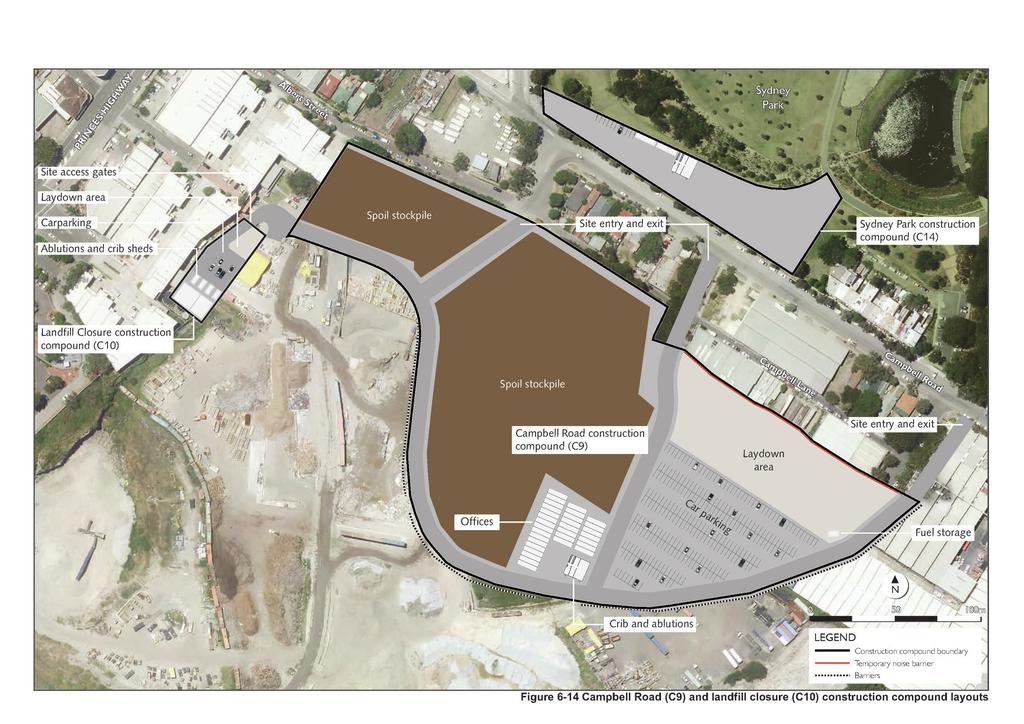
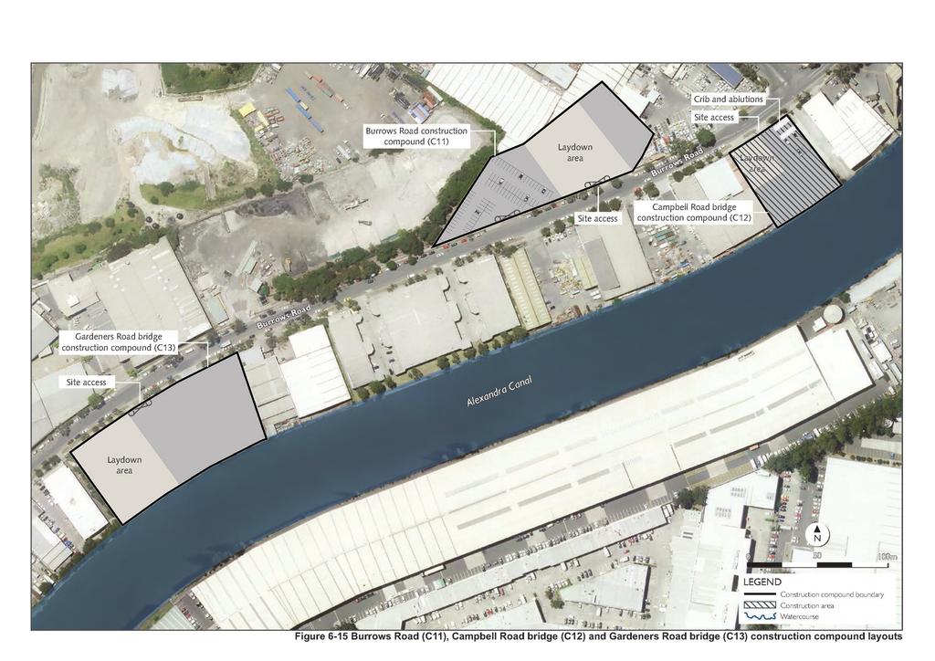
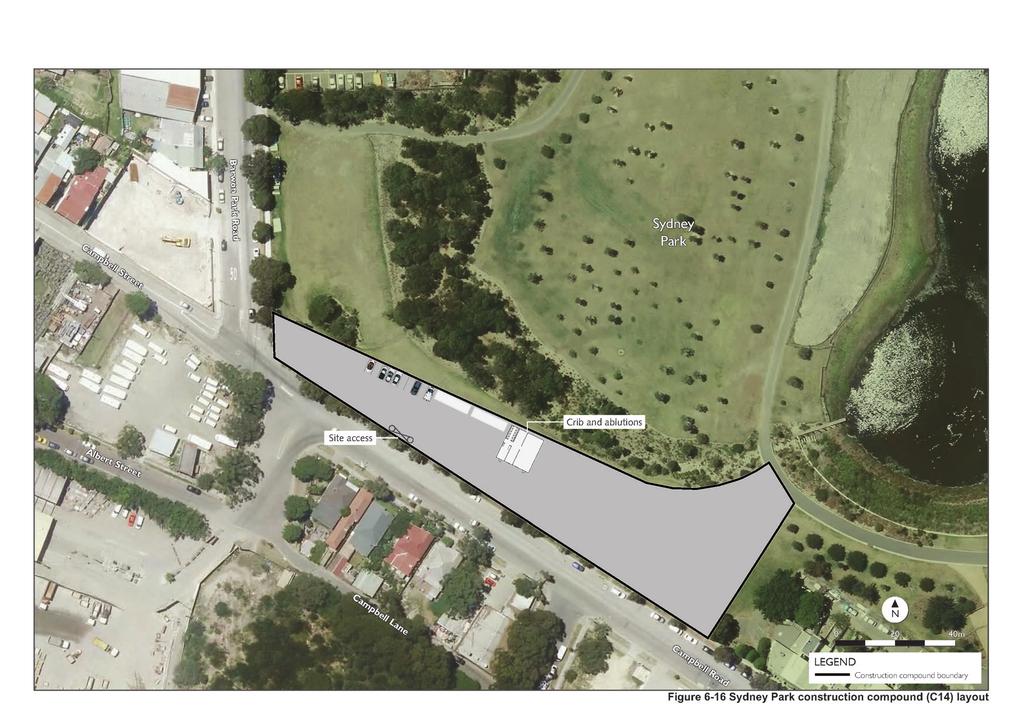
1 The land required for the Sydney Park construction compound would be used temporarily throughout construction only. The construction compound site would be rehabilitated at the completion of construction, with the exception of the areas of land required permanently for the footprint of the bridge and pedestrian and cycle paths. An indicative program for works to be conducted within the Sydney Park construction compound is provided in Table Table 6-20 Construction activity Site establishment Construction of shared path and bridge Demobilisation and rehabilitation Indicative program for the Sydney Park construction compound (C14) Indicative construction timeframe WestConnex New M5 6-33
2 (blank page) WestConnex New M5 6-34
3
4 (blank page) WestConnex New M5 6-36
5
6 (blank page) WestConnex New M5 6-38
7
8 (blank page) WestConnex New M5 6-40
9
10 (blank page) WestConnex New M5 6-42
11
12 (blank page) WestConnex New M5 6-44
13
14 (blank page) WestConnex New M5 6-46
15
16 (blank page) WestConnex New M5 6-48
17
18 (blank page) WestConnex New M5 6-50
19
20 (blank page) WestConnex New M5 6-52
21
22 (blank page) WestConnex New M5 6-54
23
24 (blank page) WestConnex New M5 6-56
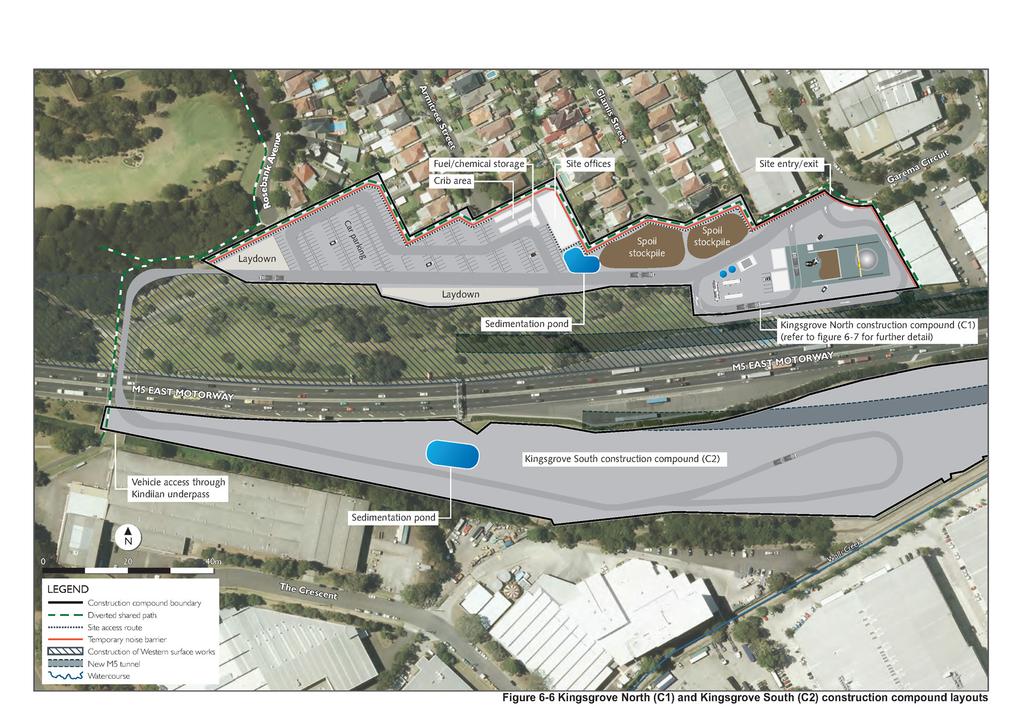
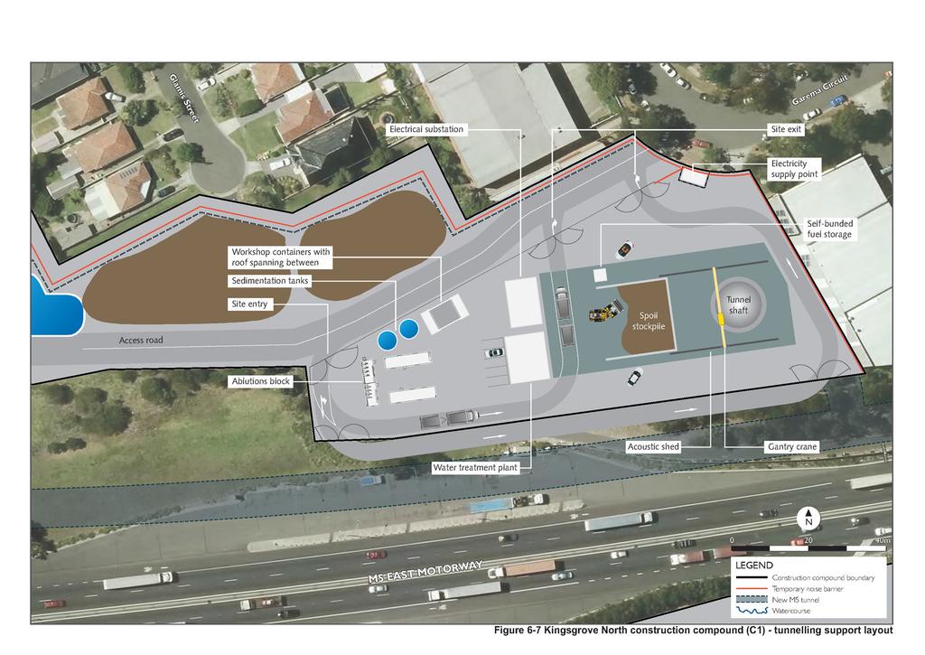
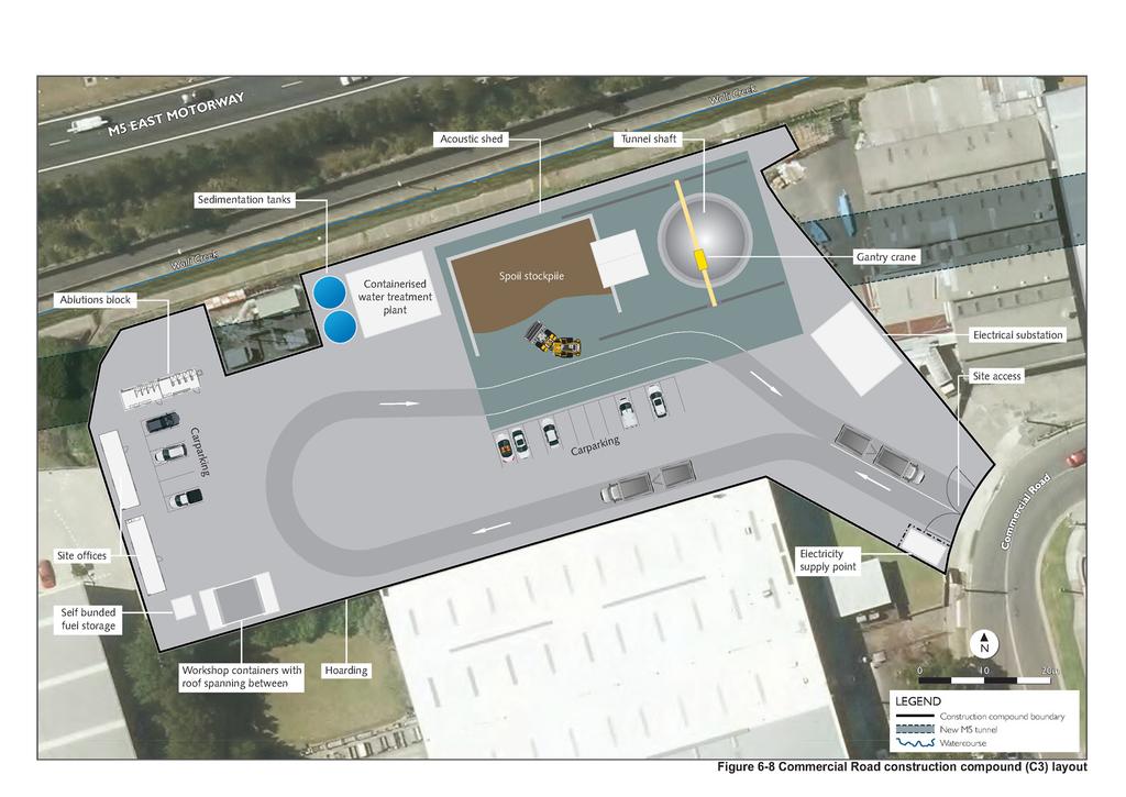
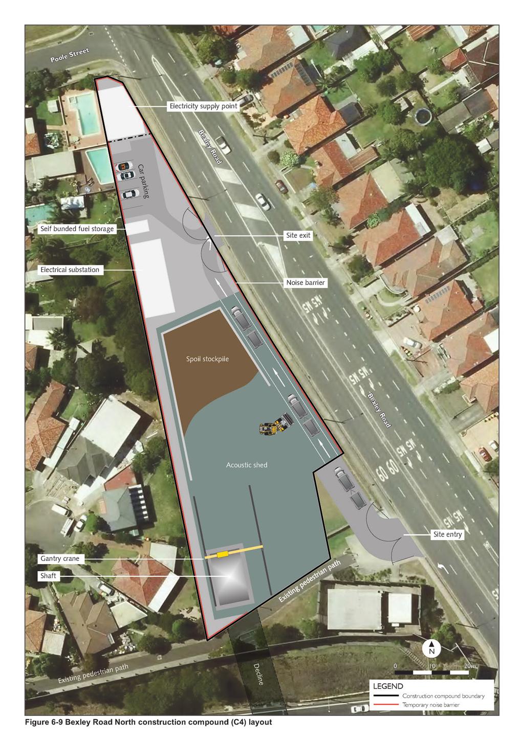
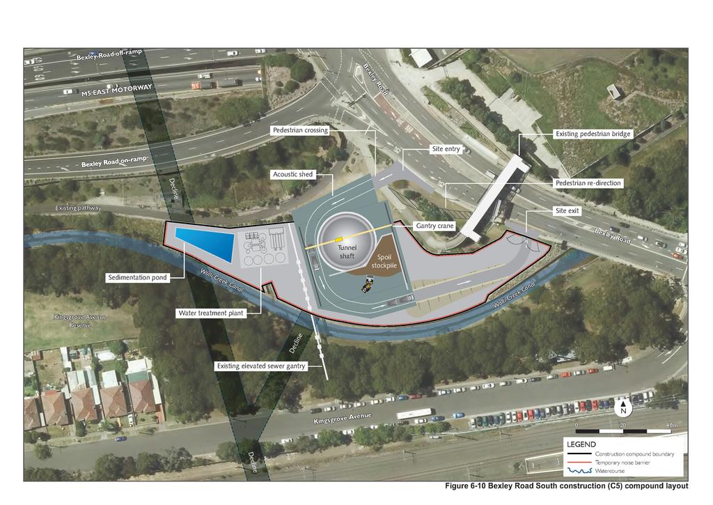
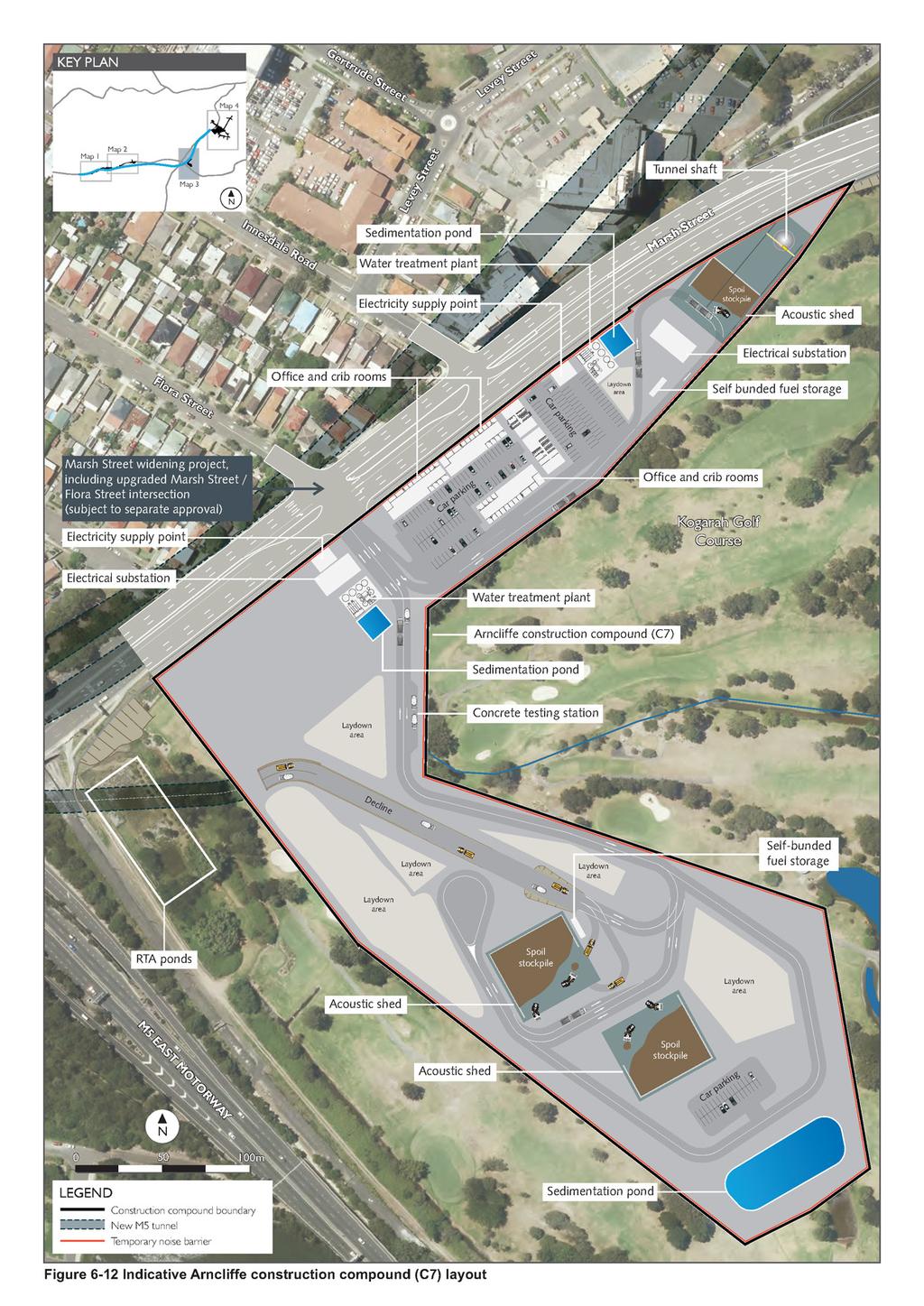
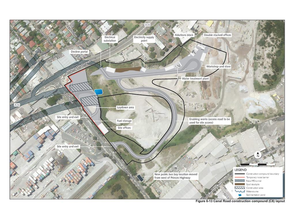
25 6.5.4 Tunnelling Construction of the project tunnels would require excavation, civil finishing works and fit-out with operational systems. Tunnel excavation The project would involve tunnel excavation for: The main alignment tunnels (two tunnels each about nine kilometres in length), including the St Peters caverns and the southern extension caverns Cross passages between the mainline tunnels at approximately 120 metre spacing for emergency pedestrian egress Vehicular cross passages Low point sumps On-and off-ramps Stub tunnels for future connection to the possible future M4-M5 Link and the possible future Southern extension. The depth of the main alignment tunnels would vary depending on geological constraints. The maximum depth of the tunnels would be about 80 metres below the ground surface, with shallower sections on the approach to the western and eastern tunnel portals. Tunnel excavations would be carried out with roadheaders. A roadheader is a machine which comprises a boom-mounted rotating cutter head on track-mounted frames and a loader device (usually on a conveyor). Roadheader excavation method is illustrated in Figure Rock breaking and controlled blasting would be used in some areas of the tunnel excavation to improve the efficiency of excavation activities and shorten the overall excavation program. Areas that are likely to require controlled blasting would be confirmed during detailed design and refined where necessary in response to geological conditions experienced during construction. It is anticipated that controlled blasting would be suitable for cross passage and bench excavations throughout the project. Roadheaders would be launched from: The Kingsgrove North construction compound (C1) The Commercial Road construction compound (C3) The Bexley Road North construction compound (C4) The Bexley Road South construction compound (C5). The Arncliffe construction compound (C7) The Canal Road construction compound (C8). The installation of ground support, including structural lining would be carried out progressively as the roadheaders advance. Two types of structural lining would be used for the project, depending on the local geology. In relatively dry sections of tunnel (namely areas of sandstone), ground support would consist of corrosion-protected rock bolts and a primary (permanent) shotcrete lining. In wet sections of the tunnel (mostly areas of shale and shallow areas above sandstone), ground support may consist of temporary rock dowels, an initial shotcrete lining with a membrane and a secondary shotcrete lining. The tunnel cross section would be a relatively flat arched profile. The arch profile would vary slightly depending on the local geology. Indicative dimensions of the main alignment tunnels (without fit-out) are summarised in Table WestConnex New M5 6-57
26 Table 6-21 Indicative tunnel dimensions Tunnel section Width tunnel floor (metres) From the western portals to the southern extension caverns. From the southern extension caverns to the St Peters caverns. M4-M5 Link and Southern extension stub tunnels. Width arched tunnel roof (metres) Height (metres) Areas with breakdown bays Note: indicative tunnel dimensions are within Hawkesbury Sandstone and without tunnel fit-out. Widths and heights may vary locally along the length of the project due to geological constraints, and areas where additional tunnel features are present. To accommodate traffic line of sight requirements and enlargements of egress tunnels and emergency breakdown bays, some sections of the project tunnels would be widened beyond these standard widths. In addition to the space required for the traffic envelope, the tunnels would also provide space required for tunnel services, including deluge systems, drainage infrastructure, communications cables, mechanical and electrical equipment, incident response infrastructure and ventilation infrastructure. Pedestrian and vehicular cross passages would be excavated between the main alignment tunnels at regular intervals. These cross passages would be excavated using either, roadheaders, excavators and blasting. Tunnel civil finishing works On completion of the tunnel excavation, civil finishing works would be carried out, including the installation of: Roadway drainage Road pavement Road furniture Electrical substations Low point sumps Cross passages, including electrical rooms Emergency smoke extraction outlets. Tunnel fit-out Tunnel excavation and civil finishing works would be followed by fitting out the tunnel with operational infrastructure. This would include power, ventilation, fire safety systems, communications infrastructure, traffic control, tunnel lighting and the operational management control systems and secondary tunnel lighting (refer to Section 5.8.2). WestConnex New M5 6-58
27 TUNNEL EXCAVATION METHOD - PLAN Articulated dump truck Spoil conveyor Road header Cutting wheel Spoil conveyor Cutting wheel Articulated dump truck Road header TUNNEL EXCAVATION METHOD - ELEVATION Articulated dump truck Spoil conveyor Road header Cutting wheel Figure 6-17 Conceptual road header excavation method
28 (blank page) WestConnex New M5 6-60
29 6.5.5 Other bulk earthworks In addition to tunnel excavation, bulk earthworks would also be required for: Cut and cover structures Landfill closure Surface road works. Cut and cover structures Cut and cover is a tunnel excavation methodology that involves excavation downwards from the surface of the ground, installation of a roof structure across the top of the excavation, and backfilling with spoil or other material. Three cut and cover structures would be constructed for the project: The western main alignment tunnel portals The eastern main alignment tunnel portals The structure beneath Campbell Road as part of the potential future connection with the possible future M4-M5 Link. Typical construction activities associated with the construction of these structures would include: Piling works Construction of capping beams Excavation Installation of temporary and permanent roof beams Installation of permanent struts and form, reinforcement and pouring of whalers Form, reinforcement and pouring of base slab Finishing works. The Campbell Road cut and cover structure would be constructed to provide a connection between the St Peters interchange and future M4-M5 Link. The cut and cover structure would be constructed as part of the project to avoid repeated disruption of Campbell Road with the future construction of the future M4-M5 Link. The northern and southern sections of the cut and cover structure would be constructed offline, and the section of cut and cover immediately below Campbell Road would be constructed simultaneously with the upgrades to Campbell Road as part of the local road upgrades. Landfill closure Earthworks within the St Peters interchange site as part of the closure of the Alexandria Landfill would include constructing a raised and vegetated containment mound in the south-western portion of the site. The mound would contain around 70,000 cubic metres of material excavated from a stockpile in the north-western corner of the Alexandria Landfill site. The construction of the containment mound would be staged, with the final form of the mound being around 25 metres AHD and would be the highest point of the final landform within the St Peters interchange. The location of the stockpile mound is shown on Figure Across the Alexandria Landfill site, about 620,000 cubic metres of material would be cut during construction and an estimated total of about 556,000 cubic metres would be filled. The volume of cut material is expected to be compacted by about 10 per cent, resulting in a balanced cut and fill across the site. The classification, management and treatment (if required) of this material is described in Section of Chapter 17 (Contamination) and Chapter 24 (Resource use and waste minimisation). WestConnex New M5 6-61
30 Surface road works Earthworks would be required for the construction of aboveground sections of the project, including the western surface works, St Peters interchange and local road upgrades. Earthworks would be completed using conventional road construction methodologies including: Vegetation clearance and topsoil stripping. Mulched vegetation would be stockpiled for later reuse in site rehabilitation and landscaping works Areas of new cut and fill to design levels, including the construction of retaining walls Installation of road drainage infrastructure A Landfill Closure Management Plan is included in Appendix F (Landfill Closure Management Plan) Landfill closure The Alexandria Landfill site was acquired by the NSW Government in December 2014 and the operations of the previous landowner ceased at that time. Activities consistent with the existing planning approvals are continuing on site. Typical continuing operations include: Sorting through the various stockpiles of waste and materials stored for resource recovery Evaluating opportunities to recycle and/or recover materials for reuse Processing of materials scheduled for reuse Removing and disposing of waste materials assessed to be unsuitable for recycling/reuse, to the landfill, or to another suitably licensed landfill facility in accordance with EPA requirements Stabilisation of a cliff face landslip. A landfill closure management plan has been prepared for the project, in consultation with the EPA. Closure of the Alexandria Landfill would involve: Bulk earthworks to prepare the site for construction of the St Peters interchange Installation of a capping layer Installation of a cut off wall to minimise inflow from the Botany Sands aquifer Upgrade of the leachate management system Installation of a landfill gas collection and management system Installation of a groundwater management system. Bulk earthworks Earthworks within the St Peters interchange site as part of the closure of the Alexandria Landfill would include constructing a raised and vegetated containment mound in the south-western portion of the site. More information about the earthworks activities to be undertaken for the closure of the Alexandria Landfill is provided in Section The classification, management and treatment (if required) of this material is described in Section of Chapter 17 (Contamination) and Chapter 24 (Resource use and waste minimisation). WestConnex New M5 6-62
31 Landfill capping Landfill capping would include: Preparatory works including clearing and levelling the ground surface, where required Installation of landfill capping layers, in accordance with the landfill closure management plan. This would include the installation of the subsurface drainage and gas collection systems, where required Land forming works to the final landform for the site, in accordance with the landfill closure management plan Stabilisation and revegetation of the new ground surface. Additional detail regarding the landfill capping system is provided in Section 5.9 and Section of Chapter 17 (Contamination). Leachate management system The existing leachate management system across the Alexandria Landfill site would be retained and augmented where required to suit the final landform of the site. Upgrades to the existing leachate management system are occurring under existing consents. Augmentation of the existing leachate system as part of the project would include the installation of a new leachate barrier underneath the containment mound, upgrades to the leachate collection and transfer system and the construction of a new leachate treatment plant. The leachate collection, management and treatment system is summarised in Section and detailed in Section of Chapter 17 (Contamination). Construction activities to be undertaken as part of the works to the leachate management system within the Alexandria Landfill site would include: Installation of leachate barrier as part of the containment mound in accordance with the specifications prescribed in the Alexandria Landfill closure management plan Upgrades and augmentation of the existing leachate collection system throughout the site, including the leachate collection pipework Installation of new leachate drainage network in accordance with the landfill closure management plan, including a system of feeder and collector pipes and three leachate collection sumps Decommissioning of the existing leachate treatment plant Removal of redundant infrastructure off-site Extension and augmentation of the existing sump and well riser, and connection into the new leachate management network Construction of a new leachate treatment plant, including: Excavation, footing and base slab installation with retaining walls as required Construction of a building to house the leachate treatment plant, including construction of blockwork walls, erection a roof and columns and enclosure of building with precast walls and lightweight cladding Internal fit-out of treatment plant, including the installation of nine storage tanks, polymer blender and dosing system, dewatering screw press, sludge bun, plant control room and operations room. Gas collection and management system The gas collection and management system as part of the closure of the Alexandria Landfill would comprise both active and passive components (refer to Section 5.9). WestConnex New M5 6-63
32 The construction of the gas collection and management system would include: Drilling and installation of around 30 vertical gas extraction wells and 30 gas extraction well heads for the active gas collection system to an average depth of about 10 metres below the ground level Trenching and installation of gas collection trenches underneath the landfill capping layer Drilling and installation of around 40 passive gas vents Trenching and installation of pipework to connect the extraction wells with the flare Construction and installation of four wellhead stations Construction of a gas flare, including fencing controls for safe access Drilling and installation of between 40 and 100 subsurface gas monitoring wells around one metre below ground level Decommissioning and disposal of redundant gas collection and management system. Additional detail is provided in Section of Chapter 17 (Contamination). Groundwater management system A sub-surface cut-off wall would be installed along parts of the western, eastern and southern boundary of the landfill site. The cut-off wall would be about 10 to 12 metres deep and would replace the existing groundwater extraction system within the site. Depending on the final location and ground conditions, the cut-off wall would be constructed by one of two ways: Excavation of a trench and construction of a bentonite clay slurry wall Sheet piling of a pre-fabricated cut off wall. The final construction methodology for the cut-off wall would be confirmed during detailed design. Additional detail regarding the management of groundwater for the project is provided in Section of Chapter 17 (Contamination) and Chapter 19 (Groundwater) Construction of permanent operational infrastructure As detailed in Section 5.1, permanent operational infrastructure would be required for the ongoing management and operation of the project. This operational infrastructure would be mainly located in five motorways operations complexes: The Kingsgrove motorway operations complex (MOC1), to be constructed on the site of the Kingsgrove South construction compound (C2) The Bexley Road South motorway operations complex (MOC2), to be constructed on the site of the Bexley Road South construction compound (C5) The Arncliffe motorway operations complex (MOC3), to be constructed on the site on the Arncliffe construction compound (C7) The St Peters motorway operations complex (MOC4), to be constructed on the site of the Canal Road construction compound (C8) The Burrows Road motorway operations complex (MOC 5), including the New M5 motorway control centre, to be constructed on the site of the Burrows Road construction compound (C11). WestConnex New M5 6-64
Construction Contaminated Land Management Plan
 Construction Contaminated Land Project Name: WestConnex New M5 Project number: 15.7020.2597 Document number: M5N-ES-PLN-PWD-0033 Revision date: 1 June 2016 Revision: 01 Document Approval Rev. Date Prepared
Construction Contaminated Land Management Plan
 Construction Contaminated Land Project Name: WestConnex New M5 Project number: 15.7020.2597 Document number: M5N-ES-PLN-PWD-0033 Revision date: 18 June 2018 Revision: 03 Document Approval Rev. Date Prepared
REPORT Condition D19 Permanent Noise Barriers
 REPORT Condition D19 Permanent Noise Barriers Project Name: WestConnex New M5 Project number: 15.7020.2597 Revision date: 19/08/2016 Revision: 1 Document Approval Rev. Prepared by Reviewed by Recommended
Six above ground substations would be constructed for the project. The construction methodology for these facilities would typically involve:
 Electrical substations Six above ground substations would be constructed for the project. The construction methodology for these facilities would typically involve: Excavation, footing and base slab installation
SEARs project justification and conclusion
 31 Project justification and conclusion This chapter presents a justification for the project and a conclusion to the environmental impact statement (EIS). The justification is based on the strategic need
18 Flooding and drainage
 18 Flooding and drainage This chapter assesses flooding and drainage impacts associated with the project. The assessment includes: The identification of existing flood behaviour and drainage infrastructure
(blank page) WestConnex New M Roads and Maritime Services Environmental impact statement
 WestConnex New M Roads and Maritime Services Environmental impact statement") (blank page) WestConnex New M5 5-122 (blank page) WestConnex New M5 5-124 5.8.1 Operational management control systems and incident and emergency response The project has been designed to include control
(blank page) WestConnex New M5 5-122 (blank page) WestConnex New M5 5-124 5.8.1 Operational management control systems and incident and emergency response The project has been designed to include control
The following hazards and risks may be associated with the project during construction:
 26 Hazard and risk Environmental hazards resulting from the construction and operation of the project, and the identification of measures to avoid, mitigate or manage these risks, are addressed throughout
6 Preliminary Assessment of Construction Method and Constructability Issues
 6 Preliminary Assessment of Construction Method and Constructability Issues 6.1 Construction Approach Appendix C includes conceptual designs of the alternatives discussed below. Generally, the conceptual
The HKIE Structural Examination Written Examination
 The HKIE Structural Examination Written Examination Section 2: Design Questions (80% of the Written Examination) Date: 28 November 2014 (Friday) Time: 12:00 nn - 06:00 pm Answer ONE question only Question
3 TUNNEL PORTALS AND DIVE STRUCTURES
 SECTION 3 TUNNEL PORTALS AND DIVE STRUCTURES 3 TUNNEL PORTALS AND DIVE STRUCTURES 3.1 Design philosophy The overall design intent for tunnel portals is to create a architectural elements that are attractive
SEARs climate change risk and adaptation
 25 Climate change risk and adaptation The NSW Government has acknowledged that, despite efforts to reduce greenhouse gas emissions, some climate change is now inevitable. The Government aims to minimise
MCKAYS CREEK HYDRO-ELECTRIC POWER SCHEME ENHANCEMENT FEASIBILITY AND SCOPING REPORT PREPARED FOR SCHEME RECONSENTING
 i MCKAYS CREEK HYDRO-ELECTRIC POWER SCHEME ENHANCEMENT FEASIBILITY AND SCOPING REPORT PREPARED FOR SCHEME RECONSENTING ii Table of contents 1 Enhancement Scope of Work 1 1.1 Introduction 1 2 McKays Intake
14.0 MONITORING AND CONTINGENCY 14.1 Effects Monitoring
 14.0 MONITORING AND CONTINGENCY 14.1 Effects Monitoring An effective monitoring program provides results to: indicate whether the facility is working as expected and that the assumptions used in the assessment
29 Environmental risk analysis
 29 Environmental risk analysis A detailed environmental risk analysis was conducted as part of this environmental impact statement (EIS). This chapter outlines the environmental risk analysis process and
PROJECT DESCRIPTION CONSTRUCTION
 PROJECT DESCRIPTION CONSTRUCTION CHAPTER SEVEN 7 Project description construction This chapter describes the likely key construction activities for the project and identifies the construction sites required.
NZQA Expiring unit standard version 3 Page 1 of 6
 Page 1 of 6 Title Supervise civil construction earthworks Level 4 Credits 15 Purpose People credited with this unit standard are able to: estimate quantities of material to be excavated and calculate haul
4.0 CONSTRUCTION METHODS AND ACTIVITIES
 4.0 CONSTRUCTION METHODS AND ACTIVITIES 4.1 Introduction This chapter describes the construction methods and activities that are expected to occur during construction of the Proposed Action. The potential
Secretary s environmental assessment requirements Sustainability. Where addressed
 28 Sustainability This chapter explains how sustainability aims and principles have been applied to the design, construction and operation of the project. The chapter: Provides an overview of the concept
Shallow Cover Tunnel Under Heritage Listed Brick Buildings: Brisbane Boggo Road Busway Tunnel
 Shallow Cover Tunnel Under Heritage Listed Brick Buildings: Brisbane Boggo Road Busway Tunnel by Ted Nye, Tunnel Designer Manager, Sinclair Knight Merz and Max Kitson, Senior Geotechnical Engineer, Sinclair
DETROIT RIVER INTERNATIONAL CROSSING STUDY MAG
 DETROIT RIVER INTERNATIONAL CROSSING STUDY MAG Meeting September 5 th, 2006 1 Agenda 1. Study Update 2. Construction Staging for Tunneling 3. Other Business 2 Deep Borehole Program 3 Status Update - Engineering
Hydraulic Excavators
 Chapter 8 Hydraulic Excavators Hydraulic excavators are designed to excavate below the ground surface on which the machine rests. These machines have good mobility and are excellent for general-purpose
Pipe Jacking Association: Introduction Presentation. Lecture notes. Slide 1. Slide 2
 Slide 1 PIPE JACKING An introduction to pipe jacking prepared by the Pipe Jacking Association This introduction to pipe jacking has been prepared by the Pipe Jacking Association as an aid to engineers
Appendix 15 Estimated costs of dams
 Appendix 15 Estimated costs of dams September 2014 Brown Hill Keswick Creek Stormwater Management Plan Part B Report Earth Dam Site 1 BROWN HILL CREEK DAM COST ESTIMATE FOR EARTH DAM ( OPTION 1) AT SITE
Electrical Work. NOV Embankments Over Swamps and Compressible Soils
 GENERAL & CONSTRUCTION S OPS GENERAL CONDITIONS OF CONTRACT NOV 2006 100 OPS General Conditions of Contract DIVISION 1 - GENERAL S 106 Electrical Work 120 180 The Use of Explosives General Specification
Roads and Maritime Services
 November 2015 Prepared for Prepared by AECOM Australia The concepts and information contained in this document are the property of Roads and Maritime Services. You must not reproduce any part of this document
Oweninny Wind Farm. Oweninny Environmental Impact Statement Appendix 5B
 Oweninny Wind Farm Oweninny Environmental Impact Statement Appendix 5B Access Tracks, Hardstanding Areas, Electrical Compounds, Borrow Pit And Cable Laying Construction Method Statement Copyright ESB International
CHAPTER 11: WALLS.
 CHAPTER 11: WALLS MODULAR BLOCK WALL (DRY CAST) Rather than being pre-approved as systems, the components of Modular block walls (dry cast) are pre-approved separately. The approved MBW components are
3.6 Construction Methods
 Exhibit 144: Birchmount Stop Layout West Don River Bridge - Girders are adequate to accommodate LRT right-of-way and required deck widening. Supplementary support or deck strengthening may be required
204 - EXCAVATION AND BACKFILL FOR STRUCTURES SECTION 204 EXCAVATION AND BACKFILL FOR STRUCTURES. Granular Backfill (Wingwalls) (Set Price)
 (Set Price)") SECTION 204 EXCAVATION AND BACKFILL FOR STRUCTURES 204.1 DESCRIPTION Excavate for the structures as shown in the Contract Documents. Unless specified otherwise, backfill the completed structures to the
SECTION 204 EXCAVATION AND BACKFILL FOR STRUCTURES 204.1 DESCRIPTION Excavate for the structures as shown in the Contract Documents. Unless specified otherwise, backfill the completed structures to the
Eglinton Crosstown LRT Construction Liaison Committee
 Eglinton Crosstown LRT Construction Liaison Committee May 30, 2017 Agenda Eglinton Crosstown LRT Overview Eglinton Maintenance & Storage Facility Mount Dennis Station Railway Corridor West Portal & Elevated
EXECUTIVE SUMMARY. Figure 1 - Rail Deck Park Study Area. Executive Summary Rail Deck Park Engineering & Costing Study Report Page 1 of 10
 EXECUTIVE SUMMARY Background The proposal for Rail Deck Park (RDP) comprises the construction of a decking structure over the rail corridor in downtown Toronto between Blue Jays Way and Bathurst Street
Section 9: Sand Mounds. 9. Sand Mounds
 Section 9: Sand Mounds 9. Sand Mounds 9. Sand Mounds 9.1 Design...107 9.2 Installation...108 9.3 Inspection...113 9.4 Operation...113 9.5 Common technical issues...117 9.6 Case study...117 The sand mound
NOTICE OF A PROPOSED CHANGE TO AN APPROVED DEVELOPMENT
 NOTICE OF A PROPOSED CHANGE TO AN APPROVED DEVELOPMENT LEGACY PROJECT K+S Potash Canada GP November 30, 2012 TABLE OF CONTENTS 1. Introduction... 3 2. Description of Proposed Change... 4 3. Existing Environment...11
Management Plan: Hazardous Materials Removal & Demolition
 Management Plan: Hazardous Materials Removal & Demolition Kingswood School (Upper Site), Corby 1.0 Introduction 1.1 Background Lambert Smith Hampton has been instructed by Northamptonshire County Council
COMMON WORK RESULTS FOR EXISTING CONDITIONS SCHEDULES FOR EXISTING CONDITIONS
 DIVISION 02 EXISTING CONDITIONS 02 01 00 MAINTENANCE OF EXISTING CONDITIONS 1. Maintenance of site remediation, underground storage tank removal, facility remediation, and hazardous waste drum handling
Learning Legacy Document Duration of data recorded (approx.) 1
 1") Table 1: Crossrail Water Consumption Data Contract C300/C410 - Crossrail Running Tunnels - West; Bond Street & Tottenham Court Road s - Early Access Shafts & SCL Works (JV: BAM Nuttall Ltd / Ferrovial
Table 1: Crossrail Water Consumption Data Contract C300/C410 - Crossrail Running Tunnels - West; Bond Street & Tottenham Court Road s - Early Access Shafts & SCL Works (JV: BAM Nuttall Ltd / Ferrovial
introduction Introduction to Bridge and Tunnel Engineering Characteristics of ideal bridge Ideal location Factors affecting bridge type Classification
 1 introduction Introduction to Bridge and Tunnel Engineering A structure constructed over an obstacle to provide the passage Road bridge movement of traffic See NRS 2045 Cross drainage structure span greater
Construction Technology B (CON4313)
") 3 - Basement 1 Quick Revision 1.1 Problems arising from basement construction a. Excavation method. b. Surface and ground water control c. Lateral stability of basement excavation. d. Stability of adjoining
3 - Basement 1 Quick Revision 1.1 Problems arising from basement construction a. Excavation method. b. Surface and ground water control c. Lateral stability of basement excavation. d. Stability of adjoining
Requirements for Measuring and Pricing of Site Clearance
 Requirements for Measuring and Pricing of Site Clearance October 2016 TRANSPORT INFRASTRUCTURE IRELAND (TII) PUBLICATIONS About TII Transport Infrastructure Ireland (TII) is responsible for managing and
Chapter 3: Permit Procedures and Requirements
 Chapter 1: General Provisions 1 1 Short Title 1 2 Jurisdiction 1 3 Amendments and Revisions 1 4 Enforcement Responsibility 1 5 Review Process 1 6 Prior Approval 1 7 Relationship to Other Standards 1 8
Save time. Save money. Specify a fast, economical Vist-A-Wall MSE. fast and easy to install. They adapt well to curves, angles and
 bigrbridge.com Save time. Save money. Specify a fast, economical Vist-A-Wall MSE Structural Wall System for your next engineered embankment project. These historically-proven, cost-effective systems have
Details of the Proposed Action
 Details of the Proposed Action Proposed Action This alternative is based on the proposed Plan of Operations submitted to the Forest Service on June 4, 2010 by Shoshone Silver/Gold Mining Company for the
ROTARY DRILLING TECHNIQUES LARGE DIAMETER
 INTRODUCTION This paper presents details about large diameter rotary drilling techniques typically employed in the civil engineering industry. These techniques have also been applied to the resources /
Construction of a Semi-Buried Building A Super-sized Shopping Mall : The Festival Walk
 Construction of a Semi-Buried Building A Super-sized Shopping Mall : The Festival Walk Presented by Raymond Wong Wai Man, Division of Building Science & Technology, City University of Hong Kong Raymond
DIVISION 3 PAVEMENT (FLEXIBLE AND RIGID) CONSTRUCTION SPECIFICATIONS
 CONSTRUCTION SPECIFICATIONS") OPS GENERAL CONDITIONS OF CONTRACT NOV 2006 General Conditions of Contract DIVISION 1 GENERAL S OCT 92 102 Weighing of Materials NOV 2004 106 Electrical Work NOV 2003 120 The Use of Explosives APR 2006
OPS GENERAL CONDITIONS OF CONTRACT NOV 2006 General Conditions of Contract DIVISION 1 GENERAL S OCT 92 102 Weighing of Materials NOV 2004 106 Electrical Work NOV 2003 120 The Use of Explosives APR 2006
Construction Spoil Management Plan
 Construction Spoil Management Plan Project Name: WestConnex New M5 Project number: 15.7020.2597 Document number: M5N-CN-PLN-PWD-0002 Revision date: 15/12/2016 Revision: 07 Document Approval Rev. Date Prepared
BUILDING THE MERSEY GATEWAY a step by step guide
 BUILDING THE MERSEY GATEWAY a step by step guide BUILDING THE MERSEY GATEWAY a step by step guide Bridge pylons Elevated approach viaduct Supporting piers Main bridge deck Stay cables INTRODUCTION Construction
WASTE MANAGEMENT CHAPTER TWENTY-FOUR
 WASTE MANAGEMENT CHAPTER TWENTY-FOUR 24 Waste management This chapter provides an assessment of waste associated with the project and identifies mitigation measures to minimise impacts. 24.1 Secretary
ENGINEERING DIRECTIVE
 Number: E-95-001 Date: 2/2/95 ENGINEERING DIRECTIVE Ross B. Dindio (Signature on Original) CHIEF ENGINEER The purpose of this engineering directive is to formally notify ALL Department engineering personnel
Annex F Scoping Checklist
 Scoping Checklist Table F1: Scoping Checklist Table. Questions to be considered in Scoping /? Which Characteristics of the Project 1. Will construction, operation or decommissioning of the Project involve
Temporary Watercourse Crossing: Fords
 Temporary Watercourse Crossing: Fords DRAINAGE CONTROL TECHNIQUE Low Gradient Velocity Control Short Term Steep Gradient Channel Lining Medium-Long Term Outlet Control Soil Treatment Permanent [1] [1]
APPENDIX I. Conceptual Design - Salem Road and McKay Road Trunk Watermain and Sanitary Sewer
 APPENDIX I Conceptual Design - Salem Road and McKay Road Trunk Watermain and Sanitary Sewer THE CITY OF BARRIE PROJECT NO. 15M-00594-01 CONCEPTUAL DESIGN SALEM ROAD AND MCKAY ROAD TRUNK WATERMAIN AND SANITARY
Large-diameter bored piles and Large-hole drillings Applications
 Large-diameter bored piles and Large-hole drillings Applications Implenia Spezialtiefbau GmbH Robert Bosch Straße 25 D-63225 Langen Phone: +49 6103 988 345 Fax: +49 6103 988 277 Email: info.spezialtiefbau@implenia.com
Dry structural excavation is usually done with front-end loaders, bulldozers or backhoes.
 1.1 Excavation - General Excavation is the removal of all material (including ice, water, etc.) required for the construction of foundations or substructures as indicated on the drawings or as determined
E. CONSTRUCTION PROCEDURES
 E. CONSTRUCTION PROCEDURES The Project facilities would be constructed in accordance with established electric utility practices, best management practices, final engineering plans, CL&P s specifications
An Introduction to. By Michael L. Schumaker, P.E. An Introduction to Shaner Industries Metal Foundation System
 An Introduction to Metal Foundation System By Michael L. Schumaker, P.E. Introduction Various types of deep foundations are routinely used to support structures. Selection of the appropriate type of deep
Environmental Assessment Chapter 8 Surface Water
 Environmental Assessment Chapter 8 Surface Water 8.2.7 Rainfall and Evaporation Based on recorded data for the area of interest, the mean annual rainfall is about 700mm, with maximum monthly rainfalls
SECTION GENERAL EXCAVATION
 02210-1 of 11 SECTION 02210 GENERAL EXCAVATION 02210.01 GENERAL A. Description 1. General excavation shall include but not necessarily be limited to, excavation and grading for general site work, roadways,
SECTION SOILS REPORT
 SECTION 02300 SOILS REPORT 1. GENERAL: 1.1 All work included under this heading shall be subject to the General Conditions of the entire operation. This Contractor is required to refer especially thereto.
Civil Engineering Construction I (CBE5031)
") Civil Engineering Construction I (CBE5031) Basement 1 1 Quick Revision 1.1 Problems arising from basement construction a) Excavation method. b) Surface and ground water control c) Lateral stability of
Civil Engineering Construction I (CBE5031) Basement 1 1 Quick Revision 1.1 Problems arising from basement construction a) Excavation method. b) Surface and ground water control c) Lateral stability of
Kiewit Approach for Tunnel Stabilization and Sewer Pipeline Replacement Project
 South Coast Water District Kiewit Approach for Tunnel Stabilization and Sewer Pipeline Replacement Project Board of Directors January 14-15, 2013 Overview of Construction Plan Highlights of Kiewit s Construction
21 July Anthony Yeates RATCH-Australia Corporation Limited Level 7, 111 Pacific Highway North Sydney NSW 2060
 AECOM Australia Pty Ltd Level 21, 420 George Street Sydney NSW 2000 PO Box Q410 QVB Post Office NSW 1230 Australia www.aecom.com +61 2 8934 0000 tel +61 2 8934 0001 fax ABN 20 093 846 925 21 July 2015
Annex L. Project Risk Analysis Matrix
 Annex L Project Risk Analysis Matrix L1 Table L1 Project Environmental Risk Analysis Local Road upgrades: Loss/damage cultural heritage values Low Acceptable Loss/damage of biodiversity value, EEC Construction
Earthwork Methods - Introduction. 1 Phase 1, Month 2
 Date 1 May 2014 Job No/Ref TN-P2-CE-001 Earthwork Methods - Introduction This note provides a summary of the possible earthworks methods and plant to be employed during construction of the main shaft platform,
Stage 2: WestConnex M5 King Georges Road Interchange Upgrade. Appendix B7 Construction Waste Management Plan
 Stage 2: WestConnex M5 King Georges Road Interchange Upgrade Appendix B7 Construction Waste Management Plan JULY 2016 DOCUMENT CONTROL File name Report name CEMP App B7 CWMP Rev D Construction Waste Management
WEIGHBRIDGE FORMAT SPECIFICATIONS
 WEIGHBRIDGE FORMAT SPECIFICATIONS TABLE OF CONTENTS PAGE WEIGHBRIDGE TERMINOLOGY...2 ABOVE GROUND WEIGHBRIDGE CONSIDERATIONS...3 SEMI-PIT WEIGHBRIDGE CONSIDERATIONS...4 CUSTOM SEMI-PIT WEIGHBRIDGE CONSIDERATIONS...5
Detailed Estimating-Introduction. Dr. Al-Hammad
 Detailed Estimating-Introduction By Dr. Al-Hammad Outline Introduction Successful Construction Estimating The Detailed Estimating Procedure The stretch - out - Length concept (SOL) Site Work and Excavation
SECTION TRENCHING
 SECTION 31 23 17 TRENCHING PART 1 GENERAL 1.1 SUMMARY A. Section Includes: 1. Excavating trenches for utilities and utility structures. 2. Bedding. 3. Backfilling and compacting to subgrade elevations.
APPENDIX N RICHARD SIMONDS GROUNDWATER REPORT
 APPENDIX N RICHARD SIMONDS GROUNDWATER REPORT Technical memo - Specialist Unit To: Nicola Broadbent, Team Leader - North West Resource Consenting Unit, Auckland Council From: Richard Simonds, Senior Specialist
Red and Purple Lines Update
 Red and Purple Lines Update Presentation to the Senate Budget and Taxation and House Appropriations Committees Department of Legislative Services Office of Policy Analysis Annapolis, Maryland July 21,
VOLUME IV DESIGN AND OPERATIONS REPORT CAPITAL REGION RESOURCE RECOVERY CENTRE
 VOLUME IV DESIGN AND OPERATIONS REPORT CAPITAL REGION RESOURCE RECOVERY CENTRE APPENDIX D Construction and Demolition Processing Facility Design and Operations Report No. 12-1125-0045/4500/vol IV APPENDIX
17 Contamination. in the Technical working paper (Contamination)
") 17 Contamination This chapter provides a summary of the Technical working paper: Contamination (Appendix O), which was prepared to inform this environmental impact statement (EIS) and address the Secretary
17 Contamination This chapter provides a summary of the Technical working paper: Contamination (Appendix O), which was prepared to inform this environmental impact statement (EIS) and address the Secretary
The HKIE Structural Examination Written Examination 2017
 The HKIE Structural Examination Written Examination 2017 Section 2: Design Questions (80% of the Written Examination) Date: 5 December 2017 (Tuesday) Time: 12:00 nn 06:00 pm (Duration: 6 hours) Question
Modular System Advantages
 Modular System Advantages The Modular System advantages can be summarised as follows: Truly Modular Off-site build Competitive cost Multi-storey capability Fits any shape, any size Fast programme completions
(Old examination format for reference only)
") The Institution of Structural Engineers Associate-Membership Examination 11 APRIL 2003 INSTRUCTIONS TO CANDIDATE 1. The examination comprises two sessions separated by a lunch break of 1 2 hour, during
The Institution of Structural Engineers Associate-Membership Examination 11 APRIL 2003 INSTRUCTIONS TO CANDIDATE 1. The examination comprises two sessions separated by a lunch break of 1 2 hour, during
7. Draw an equipment set up for the production of a beam by post tensioning. 10. What are the common concrete structures which are produced by
 Construction Technology B (CON4313) Self Assessment Questions: Chapter 1 Prestressed Concrete 1. How does the prestressing of steel tendons in prestressed concrete offer a higher loading capacity than
Patons Lane CLC Meeting
 CONTENTS 01 INSERT DIVIDER TITLE 3 02 INSERT DIVIDER TITLE 4 03 INSERT DIVIDER TITLE 5 04 INSERT DIVIDER TITLE 6 05 INSERT DIVIDER TITLE 7 06 INSERT DIVIDER TITLE 8 07 INSERT DIVIDER TITLE 9 08 INSERT
Description Accessibility Standards. University of Toronto
 Ramps The ramp must have a minimum clear width of 900 mm. The ramp must have a clear height that provides a minimum headroom clearance of 2,100 mm above the ramp. The surface of the ramp must be firm and
GRADING, FILL, EXCAVATION AND LANDSCAPING 2012 EDITION
 CHAPTER 23.105 GRADING, FILL, EXCAVATION AND LANDSCAPING 2012 EDITION Sections 23.105.101 General... 1 23.105.102 Definitions... 1 23.105.103 Permits required... 3 23.105.104 Hazards.... 4 23.105.105 Permit
New M5. Appendix U. Environmental Impact Statement. Detailed greenhouse gas calculations
 New M5 Environmental Impact Statement Detailed greenhouse gas calculations Appendix U November 2015 Appendix U. Greenhouse gas calculations U.1 Methodology The following steps have been taken in estimating
Misan University - College of Engineering Civil Engineering Department
 CHAPTER 2 Soil and Excavations Soil investigation including two phases: surface investigation and subsurface investigation Surface investigation involves making a preliminary judgment about the site s
GRADING, EROSION AND SEDIMENTATION CONTROL
 SECTION 500 GRADING, EROSION AND SEDIMENTATION CONTROL 501 Erosion and Sedimentation Control Plan All engineering plans for projects that propose to construct new, or modify existing drainage facilities,
Case study The construction of the West Rail Tsing Kwai Tunnel from Mei Foo to Tsuen Wan
 Case study The construction of the West Rail Tsing Kwai Tunnel from Mei Foo to Tsuen Wan West Rail Tsing Kwai Tunnel Location of major Tunnel Portal West Rail Tsing Kwai Tunnel Construction Features -
Geotechnical Investigation Long Timber Brewing Building Highway 99 and Kelly Street Monroe, Oregon TABLE OF CONTENTS
 Highway 99 and Kelly Street TABLE OF CONTENTS PROJECT INFORMATION... 1 FIELD EXPLORATION... 1 SITE CONDITIONS... 2 Surface Conditions:... 2 Subsurface Conditions:... 2 FILL.... 2 Topsoil.... 2 Clay Alluvium....
REPORT. Review of Application TE KUHA MINE. 22 December Submitted to: Department of Conservation 10 Sewell St Hokitika 7810
 REPORT 22 December 2014 Review of Application TE KUHA MINE Submitted to: Department of Conservation 10 Sewell St Hokitika 7810 Table of Contents 1 Introduction 3 2 Mine Planning 3 3 Access Road 3 4 Pits
Appendix. Groundwater impact assessment
 Appendix R Groundwater impact assessment Westconnex M4 East September 2015 Prepared for Prepared by GHD Australia The concepts and information contained in this document are the property of WestConnex
Contaminated Land Management
 Contaminated Land Management Helen Jones WSP Speaker Introduction Helen Jones WSP 2 Technical Executive in Contaminated Land Management at WSP. BSc Hon degree in Engineering Geology 22 years experience
Section 8: Amended Soil Mounds. 8. Amended Soil Mounds
 Section 8: Amended Soil Mounds 8. Amended Soil Mounds 8. Amended Soil Mounds 8.1 Design...95 8.2 Installation...96 8.3 Inspection...101 8.4 Operation...101 8.5 Common technical issues...105 8.6 Case study...105
SPECIFICATION FOR ENGINEERED FILLS
 SPECIFICATION FOR ENGINEERED FILLS This specification is intended to be used for the engineered fill. The specification is suitable for most purposes but there may be special conditions existing at some
1993 Specifications CSJ'S & SPECIAL SPECIFICATION ITEM Tree Preservation and Treatment
 1993 Specifications CSJ'S 0912-71-554 & 0912-71-555 SPECIAL SPECIFICATION ITEM 1016 Tree Preservation and Treatment 1. Description. This section specifies the requirements for protecting trees and related
Ground Freezing for Tunnel, Shafts, and Adits
 Ground Freezing for Tunnel, Shafts, and Adits Joseph A. Sopko, Adam Curry Moretrench American Corporation Bianca Messina Skanska USA Civil Stephen Njoloma McMillen Jacobs Associates ABSTRACT Construction
Diaphragm wall Construction
 Diaphragm wall Construction Diaphragm wall is a continuous wall constructed in ground in to facilitate certain construction activities, such as: a) As a retaining wall b) As a cut-off provision to support
204 - EXCAVATION AND BACKFILL FOR STRUCTURES SECTION 204 EXCAVATION AND BACKFILL FOR STRUCTURES
 SECTION 204 EXCAVATION AND BACKFILL FOR STRUCTURES 204.1 DESCRIPTION Excavate for the structures as shown in the Contract Documents. Unless specified otherwise, backfill the completed structures to the
- Earthwork Operations & Equipments
 - Earthwork Operations & Equipments Earthwork Operations Those construction processes that involve the soil or earth in its natural form and that precede the building of the pavement structure itself Basic
Refer to Chapter 3.0 (Description of Development) for a detailed site and development description.
 for a detailed site and development description.") 7. WATER: HYDROGEOLOGY & HYDROLOGY 7.1 Introduction This chapter of the EIAR comprises of an assessment of the likely impact of the proposed development on the surrounding surface water and hydrogeological
7. WATER: HYDROGEOLOGY & HYDROLOGY 7.1 Introduction This chapter of the EIAR comprises of an assessment of the likely impact of the proposed development on the surrounding surface water and hydrogeological
Technical Data
 4906-17-05 Technical Data (A) PROJECT AREA SITE have occurred in this section. (1) Geography and Topography have occurred in this section. (2) Aerial Photography have occurred in this section. (3) Site
Carpinteria Avenue Bridge Replacement Project Description Introduction
 Carpinteria Avenue Bridge Replacement Project Description Introduction The City of Carpinteria is proposing to replace the existing Carpinteria Avenue Bridge over Carpinteria Creek (Br. No. 51C 0172) with
Annex V Concrete Structures Removal Plan
 Appendix D Annex V Concrete Structures Removal Plan Figure V1 Lower Granite Sequences of Concrete Removal and Cofferdam Figure V2 Little Goose Sequence of Concrete Removal and Cofferdam Figure V3 Lower
Temporary Watercourse Crossing: Culverts
 Temporary Watercourse Crossing: Culverts DRAINAGE CONTROL TECHNIQUE Low Gradient Velocity Control Short Term Steep Gradient Channel Lining Medium-Long Term Outlet Control Soil Treatment Permanent Symbol