Mounting instructions. novotegra for trapezoidal metal - roof parallel
|
|
|
- Priscilla Knight
- 6 years ago
- Views:
Transcription


1 Mounting instructions novotegra for trapezoidal metal - roof parallel I
2 TABLE OF CONTENTS 1 Notes Maintenance of the mounting system novotegra for trapezoidal metal - roof parallel System components, tools and equipment What is required for mounting Mounting system components mounting versions Mounting system components optional Installing the substructure Direct attachment: clamping system Module mounting: clamping system Clamping system mounting versions Direct attachment: insertion system Module mounting: insertion system Insertion system mounting versions Warranty / product liability (exclusion) II


3 1 Notes Safety information Mounting tasks may only be carried out by qualified and competent persons. During the work protective clothing in accordance with the relevant national regulations and guidelines must be worn. Mounting must be carried out by at least two persons to ensure help in case of an accident. All relevant national and locally applicable health and safety regulations, accident prevention regulations, standards, construction standards and environmental protection regulations as well as all regulations of the employers liability insurance associations must be complied with. The national regulations for working at height / on the roof must be complied with. Electrical work must be carried out in compliance with the national and locally applicable standards and guidelines and the safety rules for electrical work. Earthing / equipotential bonding of the mounting system must be carried out in accordance with the national and locally applicable standards and guidelines. Categorisation into hazard classes To alert the user of potential danger situations the hazard classes analogous to ANSI Z 535 are used. The hazard class describes the risk if the safety information is not observed. Warning symbol with signal word Hazard class analogous to ANSI Z 535 DANGER! describes an immediate danger. If it is not avoided, death or serious injury will result. WARNING! describes a potential danger. If it is not avoided, death or serious injury might result. CAUTION! describes a potential danger. If it is not avoided, light or minor injury might result. NOTE! describes a potentially harmful situation. If it is not avoided, the plant or objects in its vicinity might be damaged. General information After receipt the goods must be inspected for completeness using the accompanying delivery note. BayWa r.e. Solar Energy Systems GmbH does not accept the costs, nor can we guarantee subsequent express deliveries if missing material is only noticed during mounting. Since our mounting systems are subject to continuous development, mounting processes or components may change. Therefore, please check the current status of the mounting instructions on our website prior to mounting. We are also happy to send you current versions upon request. The mounting system is suitable for the attachment of PV modules with standard market dimensions. The maximum permissible module width is 1.34 m. The usability of the mounting system for the respective project must be checked for each individual case on the basis of the roof cover / roof construction present. The roof cover / roof construction must meet the requirements of the mounting system with regard to load bearing capacity, support structure and condition. Requirements for the material of the roof construction or roof cover: Wooden components (rafters/purlins): min. strength class C24, no fungus infection or rot Tensile strength Rm, min for trapezoidal metal: steel 360 N/mm²; aluminium 195 N/mm² 1
4 The load bearing capacity of the roof / roof construction (rafters, purlins, trapezoidal metal, number of adhesive points, folded seams, etc.) must be checked by the user or a check be commissioned. Physical building aspects concerning insulation penetrations (e.g. condensation) must be taken into account by the user. Notes on mounting The components of the novotegra mounting system are intended exclusively for the attachment of PV modules. Dependent on the roof type of the building the designated mounting system components must be used. A condition for the intended use of the novotegra mounting system is the mandatory compliance with the specifications in these instructions regarding safety information and mounting. In case of unintended use and non-compliance with the safety information and mounting instructions and non-utilisation of the corresponding mounting components or use of third party components not belonging to the mounting system any warranty and liability claims against the manufacturer are voided. The user is liable for damage and resulting consequential damage to other components, such as PV modules, or the building as well as personal injury. The user must read the mounting instructions prior to mounting. Unresolved issues must be clarified with the manufacturer prior to mounting. The mounting sequence in these instructions must be adhered to. It must be ensured that a copy of the mounting instructions is accessible in the immediate vicinity of the work on site. The mounting specifications (module load, attachment, clamping areas etc.) of the module manufacturer must be observed and complied with. Prior to mounting the mounting system must be statically calculated with the loads to be assumed for the building project in accordance with the national standards. Information relevant to mounting (e.g. roof hook distance, lengths of bolts, overhang and protrusions) must be determined by the static calculation using the design software Solar-Planit.de. The permissible roof inclination for the use of the mounting system in accordance with these mounting instructions is 0 to 60 degrees. For each module two module support rails must be fitted symmetrically under the modules for the even load introduction to the substructure. Alternatively the system can be installed using insertion rails. The specified tightening torques must be adhered to and checked randomly on site. Notes on static calculations The mounting system must generally be statically calculated for each individual project using the design software Solar-planit.de. The static calculation only determines the load bearing capacity of the novotegra mounting system and also takes account of the attachment to the building (rafters, purlins, trapezoidal metal etc.). The load transfer within the building is not considered (customer static calculations). The load bearing capacity of the mounting system components is determined on the basis of the planned module layout and the underlying roof information (project data recording). Deviations from the planning on site may lead to different results. The load assumptions (load and roof division) are country-specific in accordance with the specifications of the Eurocode load standards. The determination of the loads to be assumed for Switzerland is in accordance with SIA 261. The modules may not be fitted above the gable end, ridge and eaves (increased wind load). At the ridge the modules may be fitted up to max. a theoretical horizontal line with the ridge tile and perfectly flush with the gable end. In the eaves area the modules may reach to max. the end of the roof cover due to loads. In case of an exposed building position (with wind load e.g. at the edge of a slope) or snow accumulation (e.g. dormer or catchment grill) the specifications of the Eurocode load standards or SIA 261 (Switzerland) must be taken into account by the user within his own responsibility. The design software does not consider these cases. 2

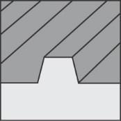
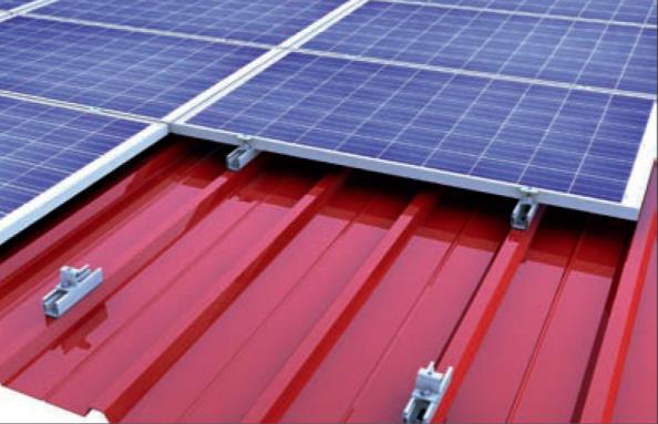
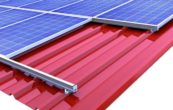
5 The static calculation of the mounting system is based on the symmetrical placement of the modules on the mounting rails at the longitudinal side of the modules for even load transfer into the substructure. For the insertion system a cross rail arrangement is expected for even load transfer. The results calculated with the design software, such as distances of the fasteners (e.g. roof hooks, hanger bolts, saddle clamps etc.), rail lengths and number of fasteners (e.g. direct attachment on the trapezoidal metal), overhang (e.g. rail and roof hook protrusions) and the other calculation notes must be considered and complied with. novotegra has been tested and certified by TÜV Rheinland: 2 Maintenance of the mounting system The mounting system must be checked for stability and operation at regular intervals during the system maintenance. In addition to the visual inspection of the components and the roof cover for damage we recommend a random inspection of the connections. Removal is possible in reverse order in the work steps mentioned below. The maintenance work must be carried out by a specialist company with proven experience in electrical systems and work on mounting systems. 3 novotegra for trapezoidal metal - roof parallel These mounting instructions describe the design of the substructure on roofs with trapezoidal or corrugated metal covering. Dependent on the mounting system design the wind and snow loads are introduced as single or line loads into the roof covering. The static verification of the mounting system only takes account of the attachment of the substructure to the roof covering. The static calculation of the roof covering based on the load from the PV construction must be carried out by the customer. The roof covering is attached with thin sheet metal screws approved by building authorities for metal strengths from 0.4 mm (steel sheet) or 0.5 mm (aluminium sheet). For aluminium sheet the use of a metal strength from 0.7 mm is recommended! For the attachment of sandwich elements to the roof shell the approval of Kingspan for sandwich type 1000 RW(IPN)/FF(MiWo) has been obtained. Alternatively to a direct attachment our mounting system solutions for corrugated fibre cement plates / sandwich covering (hanger bolt solutions) can be used. 3

 Mounting screw / set Tool: Socket AF 8 (mounting module in portrait/landscape)")


6 4 System components, tools and equipment 4.1 What is required for mounting Clamping system Figure Tool Component* Product group Short rail C47 with EPDM 385/200 mm Material: Aluminium and EPDM (mounting module in portrait /landscape) Mounting screw / set Tool: Socket AF 8 (mounting module in portrait/landscape) Middle clamps Material: Aluminium, aluminium cast and A2SS Tool: Socket AF 8 End clamps Material: Aluminium, aluminium cast and A2SS Tool: Socket AF 8 Module slip guard Material: A2SS and aluminium (mounting module in landscape/portrait) Rails Roof fixation Module attachment Module attachment Module protection and rail top cover Insertion system Figure Tool Component* Product group EPDM units Material: EPDM Seal and protection components Trapezoidal sheet bracket Material: A2SS and EPDM Roof fixation Insertion rail Material: Aluminium Rails Rail Connector IR 5 x 100 A2SS Material: A2SS Rail connectors and expansion joint EPDM-T protection IR Material: EPDM Module protection and rail top cover Edge stop set IR Material: Aluminium and A2SS Tool: Torx TX bit 30 drive Module protection and rail top cover * The components vary dependent on the roof requirements, the static calculation or the component selection and may differ from the figures above. 4


 Rail EPDM sealing strip 50 35 Material:")
 Rail Insertion system Figure")


, system design")
7 Figure Equipment Use for tools Application Battery-operated screwdriver Torque spanner up to min. 50 Nm Torque spanner up to min. 10 Nm Mounting tool --- Torx TX bit 40, 30 or 25 Socket AF 8 Special socket AF 18 deep Socket AF 8 Clamp mounting component attachments Protection Clamp mounting Trapeziodal sheet bracket Mitre saw --- Rail section 4.2 Mounting system components mounting versions Clamping system Figure Tool Component** Product group Short rail C71 with EPDM 200 mm Material: Aluminium and EPDM (mounting module in portrait) Rail EPDM sealing strip Material: EPDM (mounting module in portrait) Seal and protection components C-rail 47-2 Material: Aluminium (mounting module in portrait) Rail Insertion system Figure Tool Component** Product group EPDM tape Material: EPDM Seal and protection components Rail Connector set IR Material: Aluminium and A2SS Tool: Hexagon socket AF 3 Cross rail connector set C IR Material: Aluminium and A2SS Tool: Socket AF 13 Rail connectors and expansion joint Rail connectors and expansion joint ** Required components dependent on the substructure (e.g. rail pieces cut to size on site), system design (e.g. insertion rails on short profile) or module layout (e.g. mounting modules in landscape). 5


8 4.3 Mounting system components optional Figure Tool Component*** Product group Top cover C-rail 2,000 mm Material: Aluminium Module protection and rail top cover Grounding connector set AF 18 Material: A2SS Tool: Special socket AF 18 deep Accessories and optional components Self-locking cable ties Cable protection Cable clip d = 10 mm Cable protection *** Optionally available mounting system components e.g. for the visual enhancement of the system, cable laying or the earthing of the mounting system. 6
 defined taking into account the static calculation. The individual mounting steps for mounting modules in landscape and portrait for the clamping system (chapter 5.")
9 Module landscape Module portrait 5 Installing the substructure Prior to mounting, the module field on the roof must be measured and the position of the fasteners (e.g. roof hooks, hanger bolts, saddle clamps, short profiles etc.) defined taking into account the static calculation. The individual mounting steps for mounting modules in landscape and portrait for the clamping system (chapter 5.1) and insertion system (chapter 5.4) are explained below. Reference is made to the mounting versions (MV) for clamping systems (chapter 5.3) and insertion systems (chapter 5.6). This is followed by the corresponding work steps. 5.1 Direct attachment: clamping system Measuring short profiles Mark the mounting position of the short profiles on the trapezoidal metal raised beads dependent on the module orientation portrait or landscape, right-angled or on the raised bead and the clamping areas specified by the module manufacturer. A gap of min. 10 mm must be maintained between the modules at the short frame side. Module repeated spacing = module width B + 12 mm Alternatively according to MV 3 for portrait modules To execute the work a scaffold must have been installed in accordance with the relevant specifications. Attaching short profiles > ~17 to < ~20 mm Upper chord width > ~20 to < ~32 mm > ~32 mm The static calculation in the system planning defines the number of fasteners required for mounting modules in portrait and landscape. The selection of the fasteners for mounting is determined by the width of the raised bead and depends on the diameter (11 or 16 mm) of the sealing washer of the fasteners. For mounting modules in landscape the number of fasteners calculated with the design software is distributed on the raised bead as shown in the figure. Alternative for modules in landscape(mv1) The thin sheet metal screws must be screwed at right angles to the raised beads, fixed on both edges of the slotted holes and may not be overtightened. 7
.")


10 5.2 Module mounting: clamping system Module protection Prior to mounting modules in portrait, the module slip guards must be fitted to the frame holes above the top and bottom rail position (MV 2). For mounting modules in landscape module slip guard sets must be inserted at the lowest module row. The module slip guard for mounting modules in landscape must be tightened with a tightening torque of 50 Nm. Module clamping The modules must then be attached to the rails using end clamps and middle clamps this applies analogously also to mounting the modules in landscape. Minimum gap between modules along the short side 10 mm Mounting the middle and end clamps Insert the middle clamps or end clamps at the clamping position from above into the rail chamber. Then turn the rail nut in the rail and push the module clamps towards the module frame. Clamp position Position the end clamp or middle clamps in accordance with the adjacent figure Push the modules all the way towards the rail nut of the middle clamps. Centre clamping point To maintain the clamping position the modules must be measured on the roof in advance. Middle clamp tightening torque 10 Nm, End clamp tightening torque 8 Nm 8


11 5.3 Clamping system mounting versions Explanation of the mounting versions dependent on the design version (e.g. rail pieces, modules with box frame) MV 1 Short rail C71 with EPDM 200 mm To improve ventilation behind the modules the modules can be mounted using the short rail C71, the mounting steps must be carried out as described in chapter 5.1. Short rail C71 with EPDM 200 mm Short profile C47 with EPDM 200 mm MV 2 Mounting the module slip guard for box frame Thin metal screw Push the nut over the screw and screw the thin metal screw into the module frame without predrilling. M6 nut Reverse side Module frame The thin metal screw must not be overtightened. The approval of the module manufacturer might need to be obtained. MV 3.0 Rail pieces MV 3.1 Rail pieces cut to size on site Short rail piece: Min. on 3 raised beads EPDM Mark the mounting axes of the rail pieces on the trapezoidal metal raised beads dependent on the clamping areas specified by the module manufacturer. Mark the position of the module clamps on these axes. Determine the length of the rail pieces from the Solar-Planit calculation dependent on the clamping position (taking into account MV 3.2 and 3.3) Glue EPDM sealing strips to the raised beads in the area of the rail pieces, screw the rail pieces to each raised bead across the rail piece length. Short rail piece: Min. on 3 raised beads For rows with an even module number short rail pieces must be installed across min. 3 raised beads in the clamping area. The thin sheet metal screws must be screwed at right angles to the raised beads and may not be overtightened. Maximum rail piece length 2.0 m. Only glue the EPDM units onto dry surfaces free from dust and grease, temperatures > +5 C. 9
 between middle clamp and the next fastener in accordance with the static calculation must not be fallen below, if not observed, an extension to the next raised bead is necessary this results in the")

 must be transferred to the roof accordingly. The values can be found in the Solar-Planit calculation tools for the respective project.")

12 MV 3.2 Min / max rail length minbef Extension to the next raised bead The distance (minbef.) between middle clamp and the next fastener in accordance with the static calculation must not be fallen below, if not observed, an extension to the next raised bead is necessary this results in the min or max rail length. The values can be found in the Solar-Planit calculation tool for the respective project. MV 3.3 Positive and negative projection positive rail projection negative rail projection Rail projections are only possible at edge modules. The length of the rail pieces depends on the position of the clamping point to the next fastener. The rail length determined in the static calculation (min/max) must be transferred to the roof accordingly. The values can be found in the Solar-Planit calculation tools for the respective project. MV 3.4 Space requirement for middle and end clamps 13 mm 12 mm End clamp mounting flush with the rail end possible. Push the modules all the way towards the rail nut of the middle clamps. Middle clamp tightening torque 10 Nm, End clamp tightening torque 8 Nm. 5.4 Direct attachment: insertion system Measuring the insertion rails Insertion rail axes Modules clear width Repeated spacing Mark the mounting axes of the insertion rails on the trapezoidal metal raised beads dependent on the module orientation - portrait or landscape. Repeated spacing = module length L + 12 mm Clear rail width = module length L + 10 mm For mounting modules in landscape the module width instead of the module length must be used. Insertion system on short profiles according to MV 4 to 7. 10

 and hook it in on the other side (2). The trapezoidal sheet brackets must be hooked into the insertion rail on both sides.")

13 Gluing on EPDM units (alternatively tape) Alternatively glue onto entire insertion rail Glue the EPDM units onto every raised bead below the insertion rails. Alternatively, the EPDM tape can also be glued onto the insertion rail for small raised bead distances. Only glue the EPDM units onto dry surfaces free from dust and grease, temperatures > +5 C. Glue EPDM units onto raised beads Placing and securing insertion rails Place the insertion rail onto the EPDM strips, maintain 10 mm gap at the rail joint, Hook the trapezoidal sheet bracket into the rail on one side, feed it below the rail (1) and hook it in on the other side (2). The trapezoidal sheet brackets must be hooked into the insertion rail on both sides. 1 2 Distance of insertion rails to the roof edge at the ridge and eaves or overhang of the insertion rail at the last trapezoidal sheet bracket > 50 mm. Bead height for trapezoidal sheet bracket > 25 mm. Insertion rail attachment on short profiles according to MV 6. Fixing the trapezoidal sheet brackets 1 Position the trapezoidal sheet bracket with the aid of the mounting tool (1) on the insertion rail in the inclination of the raised bead with downward pressure. Screw the trapezoidal sheet bracket with two thin sheet metal screws into the side of the raised bead without predrilling. The trapezoidal sheet brackets must be fitted in an opposing pattern, i.e. alternating on the left and right side of the raised bead. The thin sheet metal screws must be screwed at right angles to the raised beads and may not be overtightened. 11


 and push it down against the insertion rail (3).")
 with a module inclination < 10 or as theft protection.")
14 Connecting the insertion rails Secured rail piece 10 mm gap Push the connector into the secured rail piece up to half way into the screw channel, then push the lose rail piece with the screw channel onto the connector with a 10 mm gap between the rail ends, then attach the second rail piece. Mounting Rail connector IR on short profiles according to MV 7 1/2 1/2 Push on lose rail piece Rails secured only through the connector are not permitted. Both rail pieces must be attached using trapezoidal sheet brackets. 5.5 Module mounting: insertion system Module mounting: insertion system Place the module onto the top insertion rail and push it up (1). Then lower the module onto the bottom insertion rail (2) and push it down against the insertion rail (3). Mount the next modules following the same principle, the gap between the modules must be min. 3 mm. 3 Install the EPDM-T protection IR between the modules (4) with a module inclination < 10 or as theft protection. Edge stop mounting Fit an edge stop set IR at the end of a module row at each insertion rail with a metal screw in the screw channel. The opening of the edge stop set IR must expose the drainage channel of the insertion rail. 12


15 5.6 Insertion system mounting versions MV 4 Insertion system on short profile Modules portrait Modules landscape To improve ventilation behind the modules the modules can be mounted on short profiles. The short profiles must be placed on the raised beads below the insertion rails at a distance according to the static calculation and screwed tight with the required number of fasteners. The insertion rails are measured as described above. Repeated spacing = module length L + 12 mm Clear rail width = module length L + 10 mm For mounting modules in landscape the module width instead of the module length must be used. MV 5 Attaching short profiles The number of fasteners is based on the static calculation with the fasteners shown. The thin sheet metal screws must be screwed at right angles to the raised beads, fixed on both edges of the slotted holes and may not be overtightened. MV 6 Cross rail connector IR Insert the Cross rail connector set C IR from the top into the rail groove (1), rotate the nut by 90 (2) and push the component against the insertion rail (3) until Cross rail connector set C IR engages with the mounting flange (4). The tightening torque for the Cross rail connector set C IR is 25 Nm. 13
, at the")

16 Module field MV 6.2 Position of the cross rail connector IR For the top and bottom insertion rail of the module field the Cross rail connector set C IR M8 is fitted on the inside in each case (1, 2), at the centre insertion rails the Cross rail connector set C IR M8 must be fitted alternating at the top and the bottom at the mounting flange (3) 3 Module field length = Repeated spacing x number of module fields + width of insertion rail MV 7 Mounting Rail connector IR 1/2 Centre the rail connector over the fitted rail and tighten the first threaded pin. Insert the rail to be connected into the connector, gap between the rails 10 mm, tighten the second threaded pin without play. fixe d Gap 10 mm free 1/2 - Fit connectors at the cantilever. - Threaded pin without play for longitudinal expansion 14
17 6 Warranty / product liability (exclusion) In addition to the above-mentioned regulations and safety notices the applicable regulations and rules of technology must be observed by the installing specialist company. The installer is responsible for the dimensioning of the mounting system. The installer is responsible for the connection of the interfaces between the mounting system and the building. This also includes the tightness of the building envelope. For flat roofs the roof insulation must be evaluated by the installer on site within his own responsibility regarding the material of the sealing layer, resistance, ageing, compatibility with other materials, overall condition of the roof insulation, need for a separating layer between the roof insulation and the mounting system. The required and necessary measures or precautions for the protection of the roof insulation for the mounting of the substructure of a PV system must be initiated by the installer with the aid of a specialist tradesman where necessary. BayWa r.e. Solar Energy Systems GmbH does not accept liability for faulty or inadequate measures and precautions for the protection of the roof insulation! The installer must review the friction coefficient used in the calculation for the verification of the slip safety of PV systems on flat roofs on site. Friction coefficients determined on site may be taken into account and must be provided to BayWa r.e. Solar Energy Systems GmbH for the calculation. BayWa r.e. Solar Energy Systems GmbH does not guarantee the correctness of the assumed values and is not liable for damage due to the use of incorrect values. The specifications of the module, cable and inverter manufacturers must be observed. If these contradict the mounting instructions, always consult the BayWa r.e. Solar Energy Systems GmbH sales team before mounting the novotegra mounting system or in the case of components not supplied by BayWa r.e. Solar Energy Systems GmbH the manufacturer concerned. During the preparation of the offers for novotegra by our sales staff the local conditions are not always sufficiently known, which is why changes to the offered quantities may result during installation. These changes relate mainly to the number of fasteners for the building envelope (for example roof hooks). In this case the additionally required components must always be installed in accordance with the dimensioning. BayWa r.e. Solar Energy Systems GmbH is not liable for incorrect or incomplete data collection sheets. Error-free and fully completed data collection sheets are essential for correct dimensioning. The information in the mounting instructions, the warranty terms and the information about the liability exclusion must be noted. 15
18 NOTES: 16
19 NOTES: 17


20 BayWa r.e. Solar Energy Systems GmbH Eisenbahnstraße 150 D Tübingen Tel Fax solarenergysystems.baywa-re.com Errors and changes excepted. Last updated: Sept. 2017/ASC, Version 3.4 Copyright BayWa r.e. Solar Energy Systems GmbH 18
Mounting instructions
 Mounting instructions novotegra for tile roofs top-fix I TABLE OF CONTENTS 1 Notes... 1 2 Maintenance of the mounting system... 3 3 novotegra for tile roofs... 3 4 System components, tools and equipment...
Mounting instructions. novotegra for folded seam roof
 Mounting instructions novotegra for folded seam roof I TABLE OF CONTENTS 1 Notes... 1 2 Maintenance of the mounting system... 3 3 novotegra for folded seam roof... 3 4 System components, tools and work
Solcellspaket - Poly (4.2 kwp Jinko 265W Poly) System Plan. Created with Solar-Planit by Mikael Johansson Futura Energi AB in Simrishamn.
 System Plan. Created with Solar-Planit by Mikael Johansson Futura Energi AB in Simrishamn.") Solcellspaket - Poly (4.2 kwp Jinko 265W Poly) System Plan Created with Solar-Planit by Mikael Johansson Futura Energi AB in 272 36 Simrishamn. Project YOUR PHOTOVOLTAIC SPECIALIST Company Contact Address
Solcellspaket - Poly (4.2 kwp Jinko 265W Poly) System Plan Created with Solar-Planit by Mikael Johansson Futura Energi AB in 272 36 Simrishamn. Project YOUR PHOTOVOLTAIC SPECIALIST Company Contact Address
Conergy SolarFamulus II
 Conergy SolarFamulus II Installation manual www.conergy.com Table of Contents Table of Contents SolarFamulus II for universal use on flat roofs 1 Introduction 1 1.1 Short description 1 1.2 Intended use
System Plan. Solcellspaket - Poly & Mono (NovotegraTRP20-4x4=16)
") Solcellspaket - Poly & Mono (NovotegraTRP20-4x4=16) System Plan Created with Solar-Planit by Mikael Johansson Solelgrossisten AB in 272 36 Simrishamn. Project YOUR PHOTOVOLTAIC SPECIALIST Company Contact
Solcellspaket - Poly & Mono (NovotegraTRP20-4x4=16) System Plan Created with Solar-Planit by Mikael Johansson Solelgrossisten AB in 272 36 Simrishamn. Project YOUR PHOTOVOLTAIC SPECIALIST Company Contact
System Plan. Solcellspaket - Poly (4.2 kwp - Jinko 265W Poly - TRP20)
") Solcellspaket - Poly (4.2 kwp - Jinko 265W Poly - TRP20) System Plan Created with Solar-Planit by Mikael Johansson Solelgrossisten AB in 272 36 Simrishamn. Project YOUR PHOTOVOLTAIC SPECIALIST Company
Solcellspaket - Poly (4.2 kwp - Jinko 265W Poly - TRP20) System Plan Created with Solar-Planit by Mikael Johansson Solelgrossisten AB in 272 36 Simrishamn. Project YOUR PHOTOVOLTAIC SPECIALIST Company
Mounting systems for solar technology
 Mounting systems for solar technology ASSEMBLY INSTRUCTIONS SPEEDRAIL system GB Table of contents TABLE OF CONTENTS THE COMPANY SAFETY REGULATIONS MATERIALS REQUIRED TOOLS REQUIRED ASSEMBLY 2 3 4 5 7 8
On-roof system Tau Installation manual
 On-roof system Tau Installation manual 810-0052 Table of Contents 1 Introduction 1 1.1 Short description 1 1.2 Intended use 1 1.3 Standards and guidelines 1 1.4 About these instructions 1 Tau The innovative
TRAPEZOIDAL SHEET METAL RAIL LIFT/VARIO for trapezoidal sheet metal roofs
 Photovoltaic mounting systems Assembly Instructions TRAPEZOIDAL SHEET METAL RAIL LIFT/VARIO for trapezoidal sheet metal roofs 1 Table of contents 1 Introduction 1.1 Intended use 3 1.2 About the document
INSTALLATION INSTRUCTIONS AS 2.1 CORRUGATED ETERNIT ROOF
 INSTALLATION INSTRUCTIONS AS 2.1 CORRUGATED ETERNIT ROOF ALUMERO GROUP YOUR BIG ADVANTAGE! + in-house consulting and design office + competent and reliable staff + aluminium mounting profiles and custom-drawn
TRAPEZOIDAL SHEET METAL RAIL
 Photovoltaic Mounting Systems Assembly Instructions TRAPEZOIDAL SHEET METAL RAIL Mounting system for roofing with trapezoidal sheet metal S:FLEX GmbH 09/2017 / design and engineering is subject to change
ST-AK 1/12. Photovoltaic Mounting Systems. Assembly Instructions. Mounting system for roofing with trapezoidal sheet metal
 Photovoltaic Mounting Systems Assembly Instructions ST-AK 1/12 Mounting system for roofing with trapezoidal sheet metal S:FLEX GmbH 09/2017 / design and engineering is subject to change 1 Index 1 Introduction
MANUAL. landscape orientation. portrait orientation. metal roof mounting system for solar panels METAL ROOF MOUNTING SYSTEM. Rev
 MANUAL METAL ROOF MOUNTING SYSTEM EN landscape orientation portrait orientation metal roof mounting system for solar panels ESDEC BV 2018 CONTENTS 1. Introduction 1 2. General installation conditions 1
Mounting systems for solar technology
 Mounting systems for solar technology ASSEMBLY INSTRUCTIONS S-DOME SYSTEM GB TABLE OF CONTENTS TABLE OF CONTENTS THE COMPANY SAFETY REGULATIONS MATERIALS REQUIRED TOOLS REQUIRED ASSEMBLY 2 3 4 5 8 9 Table
MOUNTING SYSTEMS APPLICATIONS OVERVIEW
 MOUNTING SYSTEMS APPLICATIONS OVERVIEW Catalogue Verion June 2013 TRITEC MOUNTING SYSTEMS: OVERVIEW OF APPLICATIONS I. Pitched Roof: Roof-Top 1. Tiles, shingles and corrugated panels 1.1 TRI-STAND on tiles
MANUAL. portrait set-up. landscape set-up. ClickFit Evo mounting system for sloping roofs with roof tiles for solar panels
 MANUAL MOUNTING SYSTEMS FOR SLOPING ROOFS WITH ROOF TILES EN portrait set-up landscape set-up ClickFit Evo mounting system for sloping roofs with roof tiles for solar panels ESDEC BV 2017 CONTENTS 1. Introduction
INSTALLATION GUIDE Sika SolarMount 1 Exposition East West
 Exposition East West CONTENTS 1 Notes on the Sika SolarMount 1 system (Exposition East West) for PV solar arrays 3 2 Setting up on site 3 3 Required Tools for mounting Sika SolarMount 1 to Sika roofing
mounting systems applications overview
 mounting systems applications overview catalogue version January 2015 tritec mounting systems: overview of applications i. pitched roof: roof-top 1. Tiles, shingles and corrugated panels 1.1 TRI-STAND
Mounting systems for solar technology
 Mounting systems for solar technology ASSEMBLY INSTRUCTIONS S-Dome Small system GB Table of contents TABLE OF CONTENTS THE COMPANY SAFETY REGULATIONS MATERIALS REQUIRED TOOLS REQUIRED ASSEMBLY 2 3 4 5
Radiant PV-RoofTopRac System Planning and Installation With Australia AS/NZS1170.2:2011 AMDT
 Radiant PV-RoofTopRac System Planning and Installation With Australia AS/NZS1170.2:2011 AMDT 2-2012 The PV-RoofTopRac System has been developed as a universal system for roof-mounting on pitched roofs.
Mounting systems for solar technology
 Mounting systems for solar technology ASSEMBLY INSTRUCTIONS CROSSRAIL TILT KIT 7 / 0 / 5 TILT FOR LOW-SLOPE AND STEEP-SLOPE ROOFS TABLE OF CONTENTS TABLE OF CONTENTS THE COMPANY SAFETY REGULATIONS MATERIALS
Clenergy ezrack SolarRoof Code-Compliant Planning and Installation With Australia AS/NZS1170
 Clenergy ezrack SolarRoof Code-Compliant Planning and Installation With Australia AS/NZS1170 The ezrack has been developed as a universal system for roof-mounting on pitched roofs. The use of patented
Mounting systems for solar technology ASSEMBLY INSTRUCTIONS. SpeedRail System.
 Mounting systems for solar technology ASSEMBLY INSTRUCTIONS SpeedRail System www.k2-systems.com Content TTTools overview 3 TTGeneral safety information 4 TTGuidelines 5 TTComponents: Portrait assembly
PITCHED ROOF. Photovoltaic Mounting Systems. Assembly Instructions. for roofing tiles, plain tiles and slate
 Photovoltaic Mounting Systems Assembly Instructions PITCHED ROOF for roofing tiles, plain tiles and slate S:FLEX GmbH 09/2017 / design and engineering is subject to change 1 Index 1 Introduction 1.1 Intended
Mounting systems for solar technology
 Mounting systems for solar technology SSEMLY INSTRUCTIONS SINGLEHOOK 1.1 SINGLEHOOK VRIO STINLESS STEEL ROOF HOOKS WITH DPTER G GENERL SFETY INFORMTION Please note that our general mounting instructions
MOUNTING SYSTEM FOR PITCHED ROOF WITH TILES. mounting system for pitched roof with tiles for solar panels in landscape setup. Rev
 MANUAL EN MOUNTING SYSTEM FOR PITCHED ROOF WITH TILES mounting system for pitched roof with tiles for solar panels in landscape setup ESDEC BV 2016 TABLE OF CONTENT 1. Introduction 1 2. General installation
Mounting systems for solar technology
 Mounting systems for solar technology ASSEMBLY INSTRUCTIONS S-DOME SYSTEM GB TABLE OF CONTENTS TABLE OF CONTENTS THE COMPANY SAFETY REGULATIONS MATERIALS REQUIRED TOOLS REQUIRED ASSEMBLY 3 4 5 8 9 Table
INSTALLATION INSTRUCTIONS TRI-STAND East-West. energy for a better world. Mounting system for PV systems with east-west orientation on flat roofs
 energy for a better world INSTALLATION INSTRUCTIONS TRI-STAND East-West Mounting system for PV systems with east-west orientation on flat roofs Quick and easy installation Aerodynamically optimized No
ON-ROOF ATTACHMENT FLAT COLLECTOR HELIOSTAR
 ON-ROOF ATTACHMENT FLAT COLLECTOR HELIOSTAR INSTALLATION INSTRUCTIONS ENERGY AND SANITARY SYSTEMS Installation requirements Generel requirements The on-roof attachment set is capable for installation of
MANUAL MOUNTING SYSTEM FOR BITUMEN / EPDM
 MANUAL MOUNTING SYSTEM FOR BITUMEN / EPDM EN mounting system for uninsulated pitched roof Bitumen / EPDM for solar panels portrait / landscape setup ESDEC BV 2015 TABLE OF CONTENT 1. Introduction 1 2.
SECURE. UNIVERSAL. MOUNTING. Tilt Kit Installation Manual
 SECURE. UNIVERSAL. MOUNTING Tilt Kit Installation Manual 1.0 INTRODUCTION... 3 2.0 KITS / PRODUCT RANGE... 4 2.1 Leg Kits... 4 2.2 Rail Kits... 4 3.0 PREPARATION FOR INSTALLATION... 5 3.1 Applications...
Mounting System MCG 3.0 Membrane-Connected Glass. System description
 Mounting System MCG 3.0 Membrane-Connected Glass System description SUNOVA MCG 3.0 System Fields of application: Not suitable for: (please inquire for other SUNOVA systems) The SUNOVA MCG 3.0 system is
Mounting systems 2018
 Mounting systems 2018 MOUNTING SOLUTIONS: TILE ROOF TRAPEZOIDAL SHEET CORRUGATED ROOF SANDWICH ROOF SEAMED METAL FLAT ROOF INSERTION SYSTEM FACADE SYSTEM 2 Electricity and the sun: For us, these go hand-in-hand.
installation instructions English
 www.creotecc.com installation instructions English Safety instructions 04 General notes 07 Material & tool requirements 08 System overview 10 installation of HANGER BOLTS 12 Maintenance 23 04 INTENDED
installation instructions English
 www.creotecc.com installation instructions English Safety instructions 04 General notes 07 Material & tool requirements 08 System overview 10 installation of CREODUR 11 Maintenance 22 04 INTENDED USE
INSTALLATION INSTRUCTIONS ENGLISH
 INSTALLATION INSTRUCTIONS ENGLISH Safety instructions 04 General notes 07 Material & tool requirements 08 System overview 10 installation of CREODUR 11 Maintenance 22 04 INTENDED USE Creotecc mounting
00MK-MA0160-EN00. Mounting System ASSEMBLY INSTRUCTIONS. Little Plan and Little Plan Light systems, for corrugated sheet metal roof
 00MK-MA0160-EN00 Mounting System ASSEMBLY INSTRUCTIONS Little Plan and Little Plan Light systems, for corrugated sheet metal roof Rev.02 November 2014 Table of contents General instructions 2 General safety
ifix INSTALLATION MANUAL PV flat roof installation system Version
 ifix PV flat roof installation system INSTALLATION MANUAL Version 2012-09-06 ifix Installation Manual Version 2012-09-06 Seite 1 Table of contents Table of contents... 1 Special characteristics of ifix...
Rack-in-a-BoxTM INSTALLATION MANUAL
 INSTALLATION MANUAL TM 1.0 INTRODUCTION 3 2.0 PRODUCT RANGE 4 2.1 Systems 4 2.2 Accessories 4 3.0 PREPARATION FOR INSTALLATION 5 3.1 Applications 5 3.2 Tools for Installation 5 3.3 Additional Materials
Mounting System MCG 3.0 Membrane-Connected Glass. System description
 Mounting System MCG 3.0 Membrane-Connected Glass System description SUNOVA MCG 3.0 System Fields of application: Not suitable for: (please inquire for other SUNOVA systems) The SUNOVA MCG 3.0 system is
Mounting System MCG 1.1 Membrane-Connected Glass. System description
 Mounting System MCG 1.1 Membrane-Connected Glass System description SUNOVA MCG 1.1 System Fields of application: Not suitable for: (please inquire for other SUNOVA systems) The SUNOVA MCG system is a lightweight
Flat roof for the loading-optimized elevation (adhesive system)
") Mounting systems Flat roof for the loading-optimized elevation (adhesive system) FLAMONT Production I Professional wholesale Adhesive mounting without roof penetration no weight easy to install low price
Mounting systems Flat roof for the loading-optimized elevation (adhesive system) FLAMONT Production I Professional wholesale Adhesive mounting without roof penetration no weight easy to install low price
INSTALLATION INSTRUCTIONS ENGLISH
 INSTALLATION INSTRUCTIONS ENGLISH Safety instructions 04 General notes 07 Material & tool requirements 08 System overview 10 installation of ALUTEC 12 Maintenance 27 04 INTENDED USE Creotecc mounting
Radiant Solar Tripod Planning and Installation Guide V1.2 With Australia AS/NZS1170.2
 Radiant Solar Tripod Planning and Installation Guide V1.2 With Australia AS/NZS1170.2 The Solar Tripod System has been developed as a universal system for roof-mounting on flat roofs. The use of patented
BiPv 2-11 Mounting Instructions
 BiPv 2-11 Mounting Instructions In-roof system for unframed modules General information The in-roof BiPv 2-11 system was designed for frameless modules and can be applied as a defi ned section of an existing
Infix ProLine Installation manual
 Infix ProLine Installation manual 80-0007 Table of contents Introduction. Overview. Intended use. Standards and technical directives.4 About this manual Theta Only the sun gets in Safety. Basic safety
2. Standard assembly system for roofs 2.1 Connection to the roof substructure 2.2 Assembly system 2.3 Module level
 1. Introduction of PROFINESS 2. Standard assembly system for roofs 2.1 Connection to the roof substructure 2.2 Assembly system 2.3 Module level 3. Outdoor system 3.1 Site / Substructure 1 Introduction
ConSole, ConSole+ Flat-roof mounting system for PV-modules and -laminates. From visions to solutions
 ConSole, ConSole+ Flat-roof mounting system for PV-modules and -laminates From visions to solutions Customized system alternatives for fast, simple and cost-effective mounting on flat-roofs and ground
INTERSOL MOUNTING SYSTEMS
 INTERSOL MOUNTING SYSTEMS PRODUCT CATALOGUE 2012 Das ist die Rubrik HIGHEST QUALITY PHOTOVOLTAICS. MOUNTING SYSTEMS FROM DONAUER SOLARTECHNIK. Donauer Solartechnik is one of the largest photo voltaic system
Installation Instructions
 Installation Instructions Flue Gas System Basic Kit GA-K - Chimney Flue Gas System for GB125 Oil Condensing Boiler For trained and certified installers Please read carefully prior to installation. 6 720
HELIOSTAR 252, 218 HORIZONTAL, FREE INSTALLATION
 HELIOSTAR 252, 218 HORIZONTAL, FREE INSTALLATION INSTALLATION INSTRUCTIONS ENERGY AND SANITARY SYSTEMS Installation requirements General requirements The free-standing installation set is to be used for
ASSEMBLY AND OPERATING MANUAL LTW SLIDE RAIL SYSTEM - Type PV
 Manufacturer: LTW Tiefbauvertriebs GmbH Holter Weg 11 D 41836 Hückelhoven-Brachelen Phone: +49 (0) 24 62 / 2009 0 Fax: +49 (0) 24 62 / 2009 15 e-mail: info@ltw-verbau.de homepage: http:\ \ www.ltw-shoring.com
Mounting systems for solar technology ASSEMBLY INSTRUCTIONS. D-Dome System.
 Mounting systems for solar technology ASSEMBLY INSTRUCTIONS D-Dome System www.k2-systems.com Content TTTools overview 3 TTGeneral safety information 4 TTRequired Materials 6 TTAssembly 9 TTNotes 17 QUALITY
SYSTEM S7-RHOMBOS INSTALLATION MANUAL
 SYSTEM S7-RHOMBOS INSTALLATION MANUAL GENERAL INFORMATION GENERAL INFORMATION This assembly manual addresses all metal ceilings manufactured by durlum. The different sections describe the related/relevant
A. Division 01: Administrative, procedural, and temporary work requirements apply to this section.
 Copyright 2016 Metal Roof Innovations, Ltd. www.s-5.com SECTION 26 31 00.01 PHOTOVOLTAIC COLLECTOR ATTACHMENT SYSTEM PART 1 - GENERAL 1.1 SUMMARY A. Section Includes: 1. Photovoltaic Collector Attachment
S 01 Modules WC I-IlI
 S 01 Modules WC I-IlI GB Installation instructions GB S 01 Contents 1 Introduction... 4 About these instructions... 4 Explanation of the symbols and signal words used... 4 Target group... 4 HEWI Support...
EASY ROOF FLAT PV FIXING SYSTEM FOR FLAT ROOF
 INS-IN02-180726 Version 1.0-24-04-18 EASY ROOF FLAT PV FIXING SYSTEM FOR FLAT ROOF For all LANDSCAPE-orientated framed modules ASSEMBLY INSTRUCTIONS Document validated by ENQUETE TECHNIQUE NOUVELLE No.
TEMPORARY EDGE PROTECTION SYSTEM DESCRIPTION CTS. Combisafe International AB
 TEMPORARY EDGE PROTECTION SYSTEM DESCRIPTION CTS Combisafe International AB CTS Combisafe International AB Contents Safety instructions... 3 Important... 4 General... 4 Data... 5 Safety posts 4140/4145/4150...
Insulation boards PhoneStar
 Sound Insulation Bavaria Insulation boards PhoneStar Installation instructions Wall Version 15.05. 2015 ONE solution universal in every area PhoneStar is an innovative, very efficient insulation board
Mounting systems for solar technology ASSEMBLY INSTRUCTIONS. S-Dome 2.0 System.
 Mounting systems for solar technology ASSEMBLY INSTRUCTIONS S-Dome 2.0 System www.k2-systems.com Content T Tools overview 3 T General safety information 4 T Required Materials 6 T Assembly 9 T Notes QUALITY
SolarStyl BIPV New Building Integrated Photovoltaic System August V13 Page 0
 SolarStyl BIPV New Building Integrated Photovoltaic System 2010 August V13 Page 0 By ArcelorMittal Stainless & Nickel Alloys SolarStyl Frame for BIPV Systems To simplify photovoltaic roof and facade design.
User instructions for photovoltaic modules 60Pxxx-V 60Mxxx-V 72Pxxx-V 72Mxxx-V 60Pxxx 60Mxxx 72Pxxx 72Mxxx
 F r e n c h P h o t o v o l t a i c M o d u l e s M a n u f a c t u r e r 20 15 July User instructions for photovoltaic modules 60Pxxx-V 60Mxxx-V 72Pxxx-V 72Mxxx-V 60Pxxx 60Mxxx 72Pxxx 72Mxxx 1 Introduction
Radiant PV-Solar Tripod System Planning and Installation With Australia AS/NZS1170.2:2011 AMDT
 Radiant PV-Solar Tripod System Planning and Installation With Australia AS/NZS1170.2:2011 AMDT 2-2012 The PV-Solar Tripod System has been developed as a universal system for tilt solar panel roof-mounting
Installation Guide EcoFoot2+ 10-Degree Ballasted Racking System Document No. ECO-002_850. Rev 1.6, January 2018
 Installation Guide EcoFoot2+ 10-Degree Ballasted Racking System Document No. ECO-002_850 Rev 1.6, January 2018 Sales: 740-249-1877 Sales@EcolibriumSolar.com Field Support: 866-488-6794 FieldSupport@EcolibriumSolar.com
Mounting systems for solar technology ASSEMBLY INSTRUCTIONS. D-Dome 2.0 System.
 Mounting systems for solar technology ASSEMBLY INSTRUCTIONS D-Dome 2.0 System www.k2-systems.com Content TTTools overview 3 TTGeneral safety information 4 TTRequired Materials 6 TTAssembly 9 TTNotes 16
BISOL EasyMount Structures
 BISOL EasyMount Structures Premium mounting solutions designed for simplicity and ease of installation. Smart solutions for every roof type Superior mechanical strength 50 MW 5 Installed in +50 MW of solar
Blast Resistant Enhanced Curtain Wall. Reference Brand: Sapa Building System Elegance 85PF GENERAL DESCRIPTION PERFORMANCE
 Blast Resistant Enhanced Curtain Wall Blast Resistant Enhanced Curtain Wall Reference Brand: Sapa Building System Elegance 85PF GENERAL DESCRIPTION Grid based thermally insulated curtain wall system with
MRac Tile Roof Installation Guide
 MRac Tile Roof Installation Guide Tile Interface 117HA AS/NZS1170.2 Content 1. Product Introduction-------------------------------------------------------P2 2. Installation Tools& Components---------------------------------------P3
SOLARWATT EASYIN SYSTEM
 nergymanager configuration Device installation Preparation and planning EN SOLARWATT EASYIN SYSTEM ROOFING FRAME INSTALLATION INSTRUCTIONS FOR MODULE EASYIN 60M STYLE K Inhaltsverzeichnis 1 General information...
GroundTrac. Installation Manual
 APPLICATION: The GroundTrac system is designed with a minimum amount of installed footings at greatly reduced labor. The system integrates with ordinary 1-1/2 schedule #40 galvanized water pipe. This ground
HelioFix Solar mounting Systems
 HelioFix Solar mounting Systems Industrial Roof Flat Roof Ground Mount Carport Mount Structural Analysis Analysis of wind loads and dead loads using STAAD Pro. 2D drafts of General Arrangement and Structural
GROUND MOUNT INSTALLATION MANUAL
 GROUND MOUNT INSTALLATION MANUAL Contents DISCLAIMER 1 CHECKLIST 2 1. ERECT BASe 3 2. CONNECT PIPES 3 3. PLACE RAILS 4 4. SECURE LUGS 4 5. CLAMP MODULES 5 DIAGONAL BRACES (OPTIONAL) 6 UNDER CLAMPS (OPTIONAL)
a-si/μcsi Tandem Module Installation Manual Macsun Solar Energy Technology Co., Limited Applied to MS-SDXX
 a-si/μcsi Tandem Module Installation Manual Macsun Solar Energy Technology Co., Limited 2014.1.20 Applied to MS-SDXX 1. 2. 3. 4. 5. CONTENT PURPOSE... 2 WARNING... 2 SCOPE... 2 RESPONSIBILITY... 2 INSTALLATION...
Mounting systems for solar technology ASSEMBLY INSTRUCTIONS. S-Dome System.
 Mounting systems for solar technology ASSEMBLY INSTRUCTIONS S-Dome System www.k2-systems.com Content TTTools overview 3 TTGeneral safety information 4 TTRequired Materials 6 TTAssembly 9 TTNotes 17 QUALITY
A. Division 01: Administrative, procedural, and temporary work requirements apply to this section.
 Copyright 2015 Metal Roof Innovations, Ltd. www.s-5.com SECTION 07 72 53 COLORGARD SNOW GUARDS PART 1 - GENERAL 1.1 SUMMARY A. Section Includes: 1. Snow guards for metal roofs. 2. [Non-penetrating] [Face
ASSEMBLY INSTRUCTIONS RESIDENTIAL SOLUTION CROSSRAIL GROUND MOUNT SYSTEM USA
 ASSEMBLY INSTRUCTIONS RESIDENTIAL SOLUTION CROSSRAIL GROUND MOUNT SYSTEM USA TABLE OF CONTENTS TABLE OF CONTENTS SAFETY REGULATIONS MATERIALS REQUIRED ASSEMBLY ENGINEERING DRAWINGS TERMS AND CONDITIONS
Installation Guide EcoFoot5D High Density 5-Degree Ballasted Racking System Document No. ES10560
 Installation Guide Installation Guide EcoFoot5D High Density 5-Degree Ballasted Racking System Document No. ES10560 Rev 1.0, September 2017 Sales: 740-249-1877 Sales@EcolibriumSolar.com Field Support:
USER S GUIDE for HAKITEC 750. TEMPORARY ROOF with HAKI Trak Sheeting ( Hand-Built )
") USER S GUIDE for HAKITEC 750 TEMPORARY ROOF with HAKI Trak Sheeting ( Hand-Built ) HAKI LTD 2007 INTRODUCTION Temporary roof structures are by their very nature amongst the most difficult and demanding
USER S GUIDE for HAKITEC 750 TEMPORARY ROOF with HAKI Trak Sheeting ( Hand-Built ) HAKI LTD 2007 INTRODUCTION Temporary roof structures are by their very nature amongst the most difficult and demanding
Layher. Keder Roof and Keder Hall. More Possibilities. The Scaffolding System. Layher Keder Roof and Keder Hall Instructions for Assembly and Use
 Layher Keder Roof and Keder Hall Instructions for Assembly and Use Certification as per DIN ISO 9001/EN 29 001 by TÜV-CERT Keder Roof and Keder Hall Layher More Possibilities. The Scaffolding System. CONTENTS
Schüco Mounting System MSE 210 Mounting on trapezoidal roofing
 Solar products Schüco Mounting System MSE 210 Mounting on trapezoidal roofing English Schüco Installation instructions: Installation instructions: MSE 210 trapezoidal roof Art. No. 259 713 08.2009-02 Printed
ConSole. Installation instructions
 onsole Installation instructions INSRTION Product Information The onsole assembly system is the ideal solution for installing PV modules on flat roofs with pitch of up to 5 without roof penetration. Most
PRR. Flush Mount Racking System. Installation Manual
 PRR Flush Mount Racking System Installation Manual Release, September 2014 Table of Contents 1. Introduction 1.1 Product Overview 1.2 About This Manual 1.3 Product Liability 1.4 Standards Compliance 1.5
EcolibriumSolar. Customer Info. Project Info. System Info. Project Design Variables. Name: Phone:
 Customer Info Name: Email: Phone: Project Info Identifier: 4765742_preinstall Street Address Line 1: Street Address Line 2: City: State: Zip: Country: System Info Module Manufacturer: Jinko Solar Module
Leveling Foot RB210. Leg Extender RLT66
 Landing for Right & Left Turn R342 ITEMS # 0254049, 0254061, 0254072, 0254076, 0016567, 0254099, 0254110, 0054116, 0254117, 0254126, 0254140, 0254150, 0254156 CUSTOM ACCESS RAMP SYSTEM MODELS # R100, R242,
Curtain Wall Stick System (Capped)
") Curtain Wall Stick System (Capped) Stick Construction Capped Curtain Wall Reference Brand: Sapa Building System Elegance 52 ST GENERAL DESCRIPTION Grid based thermally insulated curtain wall system with
Curtain Wall Stick System (Capped) Stick Construction Capped Curtain Wall Reference Brand: Sapa Building System Elegance 52 ST GENERAL DESCRIPTION Grid based thermally insulated curtain wall system with
Unitised Curtain Wall Beaded
 Unitised Curtain Wall Beaded Glazed Frame Unitised Curtain Wall Reference Brand: Sapa Building System Elegance 72 GF GENERAL DESCRIPTION Unitised curtain wall system using glazing beads for glass retention.
SOLAR-LINE. Roofing accessories for solar systems. Providing expertise in the installation of photovoltaic and solar thermal systems
 SOLAR-LINE Roofing accessories for solar systems Providing expertise in the installation of photovoltaic and solar thermal systems Expertise in solar energy systems Klober s expertise can play an important
TYPICAL ROOF CONDITION LAYOUT
 FIXED POINTS TYPICAL ROOF CONDITION LAYOUT 15 17 9 16 29 12 14 11 3 7 35 20 6 23 30 31 24 13 18 Typical Roof Condition Layout... 1 Low Eave Isometric View - Fixed/ Floating... 2 Low Eave Section - Fixed/
Tindo Karra. Installation and Specifications Manual. Introduction
 Tindo Karra Installation and Specifications Manual Introduction Thank you for choosing a Tindo Solar Module. Background to our name TINDO Tindo is a word from the Kaurna warra Aboriginal language which
Installation instructions
 Installation instructions IBC AeroFix Date: 30-Jun-2015 1 Contents 0. Introduction... 3 01. Tool list... 4 02. General information, standards and regulations... 4 03. System variants... 8 04. Technical
Architectural Roof and Wall Products Guide Specifications
 Architectural Roof and Wall Products Guide Specifications Western States Metal Roofing 901 W. Watkins St. Phoenix, AZ 85007 PH: 602-495-0048 FX: 602-261-7726 FORMED METAL WALL PANELS This Guide Specification
The Racking System Designed By Installers for Installers
 The Racking System Designed PV Racking Ground System Installation Instructions Key benefits: Easy installation. No clamps! No more straining to lean over and fasten bolts! Module installation time is far
Installation and Operation Manual
 Installation and Operation Manual Solarion M210T General Information This document contains important information for the installation of Solarion M210T solar modules from OC3 AG. Please read this document
S7 Taifun Installation Manual
 CEIL ING LIGHTING AMBIENCE S7 Taifun Installation Manual GENERAL INFORMATION GENERAL INFORMATION This assembly manual addresses all metal ceilings manufactured by durlum. The different sections describe
Installation instructions
 Installation instructions 20 Jahre Qualität in Solartechnik - mit System SOL-50 in-roof system Qualität in Solartechnik - mit System Qualifiziertes Montagesystem für Photovoltaikanlagen Solare Energiesysteme
INSTALLATION INSTRUCTION AEROCOMPACT S5
 INSTALLATION INSTRUCTION AEROCOMPACT S5 Flat-roof mount for PV installations IN. AEs5 US 2014.1 the unbeatable flat-roof solution YOUR BIG ADVANTAGE + 25 years product warranty + Best price value available
Solar products. Schüco mounting system MSE 210 flat roof
 Solar products Schüco mounting system MSE 210 flat roof Schüco Allgemeines Content General...3 Safety instructions for MSE 210 fl at-roof installation...4 Explanation of pictograms used...5 Tools required...6
Festoon Manual Heavy Duty C-Track
 Festoon Manual Heavy Duty C-Track 966300.3 Heavy Duty C-Track Manual CONDUCTIX INCORPORATED The technical data and images which appear in this manual are for informational purposes only. NO WARRANTIES,
Installation instructions. LORO-ATTIKASTAR siphonic drains
 instructions with clamping flange, for pressure flow for bituminous or plastic roof sealing sheets, according to EN 1253, steel, hot-dip galvanised consist of the drain body and the stainless steel suction
PREFA Aluminiumprodukte GmbH Page 1 of 21
 Tender Specifications 120901 PREFA Shingles_2012 ---------------------------------------------------------------------------------- 01. Text GENERAL PRELIMINARY REMARKS Roof ----------------------------------------------------------------------------------