TION GUIDE ALLA T INS
|
|
|
- Gwendoline Robbins
- 6 years ago
- Views:
Transcription


1 INSTALLATION GUIDE
2 TENSAR GEOGRIDS Easier installation makes the Sierra Slope Retention System a more affordable alternative to conventional retaining walls. The Sierra System owes its strength and durability to Tensar Uniaxial (UX) Geogrids, Tensar International Corporation s patented reinforcement geogrids. Due to their stiff interlocking capabilities, these geogrids stand the test of time, performing better than other commercially available geosynthetics. For more information, visit Introductionl In worldwide use since 1982, the Sierra Slope Retention System continues to be the premier reinforced soil slope (RSS) solution of choice among owners and developers, engineers, architects and contractors alike. Developed by Tensar International Corporation (Tensar), the world leader in geogrid technology and engineering ingenuity, Sierra Slopes ensure a combination of performance, economy and beauty that is unmatched by other types of earth retention systems. The Sierra System is a complete and fully integrated Mechanically Stabilized Earth (MSE) System. Each of the system s components have been specifically designed and detailed to work together for optimum efficiency and performance. Furthermore, these components create a structural solution whose integrity and dependability have been proven in a variety of challenging site conditions such as the support of buildings and earthquake loadings. The following steps provide a general guideline for installing the Sierra Slope Retention System. These steps will help you through standard installation procedures from your project s start to finish. If you are installing a Sierra Slope and require more detailed information, please refer to the project s installation instructions, the drawings within the contract bid documents or consult your local Tensar representative. TOOLS REQUIRED Circular saw with masonry blade Sawhorses and plywood for constructing a worktable to cut the geogrids Steel pipe for unrolling geogrids on the worktable Steel U pins for securing geogrid to the ground Spray paint (one color for each type of geogrid, if more than one type of Tensar Geogrid is used) SIERRA System Components COMPONENT Tensar Uniaxial (UX) Geogrids Tensar Biaxial (BX) Geogrids Site-Specific Facing System Full Engineering and Construction Services FUNCTION Primary reinforcement that internally reinforces structure and fill materials. Secondary reinforcement that ensures surficial stability of the slope structure. Provides aesthetic value by offering multiple facing options, including bioengineering. Detailing, design, construction services, drawings, quality control testing, construction installation.
 Geogrid is specified (Figure 1).")
.")
.")
3 Figure 1: Color coding the geogrid rolls. 1. Cutting Tensar Geogridsl 2. Site Excavation & Drainage l Color code the ends of the Tensar Geogrid rolls if more than one type of Uniaxial (UX) Geogrid is specified (Figure 1). Cut Tensar Geogrids to the lengths shown on the construction drawings (from the first rib to the last rib). Lengths shown on drawings do not include fingers. Make the cut next to the heavy transverse ribs that span the width of the geogrid roll. Cut geogrids flush at the nearest transverse bar beyond the measured length (Figure 2). Excavate to the lines and grades shown on the construction drawings or as directed by the engineer. To improve stability, it is recommended that the sidehill embankments be benched into competent soil or rock (Figure 4, top of page 3). Use drainage composite as specified in the drawings, and install the drainage system according to the construction drawings (see Figure 4, inset top of page 3). To easily cut geogrids, use a circular saw on a worktable (Figure 3). As geogrid lengths are cut, mark and tag them according to the length and type, and then stockpile them for later use. Note: The correct geogrid type and lengths must be used at each lift level according to the project s design. Cut line Measured length Figure 2: Cut geogrid. Figure 3: Cutting geogrid with a circular saw. 2


.")

.")
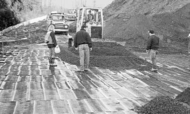
4 Drainage Composite Figure 4: Benching the backcut and typical placement of drainage composite. 4. Primary Geogrid Placementl 5. Fill Placementl Tensar UX Geogrids are most often used as primary reinforcement, and Tensar BX Geogrids are typically used as secondary or surficial reinforcement. UX Geogrids are supplied in roll widths of 4.3 ft (1.3 m). The use of BX Geogrids as surficial reinforcement is discussed in Section 6 of this guideline. Place geogrid rolls perpendicular to the slope (Figure 5) with the transverse bar end of the geogrid at the slope face. Geogrid strips should extend back from the slope face to the distance specified on the construction drawings and must be placed at the elevations shown on the construction drawings. Short pieces of UX Geogrids can be spliced using flat polymer bodkin slats available from Tensar (shown right). Fill can be placed and spread directly upon the geogrids with rubber tired equipment (Figure 6). Keep speeds slow and avoid turns and stops on the geogrids. If needed, the geogrids can be secured into place to prevent movement during fill placement. Use pins, staples, sandbags, small piles of soil, etc. as anchors. Spread and level the soil (Figure 7). Do not drive tracked equipment on exposed geogrids. Adjacent geogrid strips should be butted together sideby-side without overlap unless a gap between the strips is specified. Note: A small covering may be specified for wrap around construction. Check construction drawings. Figure 5: Unrolling and orienting the primary reinforcment UX geogrids. Figure 6: Place fill. Figure 7: Spread and level fill.

. Embedments of BX Geogrids may be required to provide stability of the slope surface. Generally, the BX Geogrids will be unrolled parallel to the slope (Figure 10).")

5 Figure 8: Compact fill. 6. Compaction l 7. Surficial Reinforcementl Compact the soil to the specified density using standard compaction equipment and procedures (Figure 8). The lift thickness should be great enough to ensure that sheepsfoot cleats will not come in direct contact with the geogrid. For curved slope faces, the primary geogrids butt edge-to-edge at the slope face (unless shown otherwise on the construction drawings) and either fan out or overlap into the fill (Figure 9). Embedments of BX Geogrids may be required to provide stability of the slope surface. Generally, the BX Geogrids will be unrolled parallel to the slope (Figure 10). Tensar BX Geogrids are supplied in roll widths of 9.8 ft (3 m) or 13.1 ft (4 m). The geogrid rolls may be cut to a specified width before unrolling. Fill can be spread directly upon the geogrids. Spread and level the fill. Do not drive tracked equipment directly upon the exposed geogrids. BX Geogrids may be cut to conform to horizontal curves. Figure 9: Placing geogrids on curves. Figure 10: Installing BX Geogrid parallel to the slope. 4

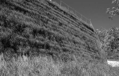
6 Figure 11: Installing turf reinforcement mat (TRM). 8. Erosion Controll Grade to top of the completed slope to ensure that water runoff is directed away from the face of the new slope. Positive drainage must be provided so that water does not collect above or behind the reinforced soil. Place the North American Green turf reinforcement mat (TRM) in position on the face of the slope and pin it in place (Figure 11). For steeper slopes, face angles greater than 1H:1V, a geogrid wrap around and form system may be used. Wire forms (Figure 12) can be utilized in conjunction with a BX Geogrid wrap (Figure 13) to aid in maintaining facing alignment. 1.5 (typ.) Support Strut Length (Measure inside hook) black wire 18.0 Wire Struts 24 C/C (typ.) Field adjust as required WWF Facing Unit TRM 3 (min.) top wrap of TRM Tensar UX or BX Geogrid Backfill 18.0 Offset varies 6 (min.) 48 (min.) top & bottom C/C max. (as required) 6 (min.) bottom of TRM Support strut Tensar BX Geogrid Maximum limit of top soil (see Note 3) 10-0 Support Strut 4 x 4 (0.225 DIA x DIA) welded wire fabric 18.0 Notes: 1. Facing to consist of prefabricated WWF 4 x 4 (0.225 DIA x DIA) forms. 2. All forms and struts will be fabricated from black wire. 3. Overall length of wire forms is Effective construction width is 9-8 with 4 overlapping at ends. Notes: 1. See welded wire form (WWF) facing unit detail for facing materials & dimensions. 2. All facing units shall be fabricated from black steel. 3. Topsoil shall be loamy sand and finer gradation with 10-15% organic content or material approved by a qualified landscape architect. Vegetation type shall be specified by a qualified landscape architect. Figure 12: Welded-wire form facing unit detail. Figure 13: Welded-wire form facing detail (plantable face fill)

 or alternatively bodkined as indicated on the construction drawings.")

7 l 9. Special Considerationsl The Engineered Advantage TMl BX Geogrids typically have different design tensile strengths in the along-the-roll and the across-the-roll directions. Therefore, it is important to install Tensar BX Geogrids in the orientation indicated on the construction drawings. If the BX Geogrid strips are placed perpendicular to the slope face, it is not necessary to overlap adjacent strips (Figure 15). However, if the geogrid strips are placed parallel to the slope face, adjacent strips should be overlapped (Figure 16) or alternatively bodkined as indicated on the construction drawings. When using LH800 Geogrids in Sierra Slope installations, it is important to note that LH800 Geogrids have design strengths across-the-roll. Therefore, it is important to install them parallel to the slope face. Tensar understands the need for sound engineering as well as proper construction techniques to assure the success of any project. To support this belief, we have a full, in-house professional engineering staff to support your design needs, and a construction operations group to provide on-site installation assistance when necessary. This additional hands-on expertise assures that your project is handled professionally and you will get the results you intend. For more information on the Sierra System, please call 800-TENSAR-1, visit or info@tensarcorp.com. We are happy to supply you with additional Sierra Slope product information, complete design guidelines, system specifications, design details, preliminary cost estimates, summaries of completed projects and much more. Roll Width Roll Width Figure 15: Tensar BX Geogrids placed perpendicular to the slope face. Figure 16: Tensar BX and LH800 Geogrids are placed parallel to the slope face. 6

8 Tensar International Corporation 5883 Glenridge Drive, Suite 200 Atlanta, Georgia TENSAR-1 Authorized Representative: 2006, Tensar International Corporation, Limited LLC, Inc. Certain products and/or applications described or illustrated herein are protected under one or more U.S. patents. Other U.S. patents are pending, and certain foreign patents and patent applications may also exist. Trademark rights also apply as indicated herein. Final determination of the suitability of any information or material for the use contemplated, and its manner of use, is the sole responsibility of the user. Printed in the U.S.A. SIERRA_IG_7.06
INS T A LLA T I O N G U I D E
 INS T A LLA T I O N G U I D E TENSAR GEOGRIDS The System is a costeffective and easy-to-install alternative for projects with grade changes. The System owes its long-term performance and durability to
A Complete Retaining Wall Solution >
 SYSTEM OVERVIEW Tensar Geogrids SierraScape Walls now offer a more affordable alternative to concrete for steep grade changes. The SierraScape System owes its strength and durability to Uniaxial (UX) Geogrids,
SIERRASCAPE RETAINING WALL SYSTEM. design and installation guide
 SIERRASCAPE RETAINING WALL SYSTEM design and installation guide The Retaining Wall System is a more affordable alternative to concrete panel or block walls for various grade change challenges. Engineers
APPLICATION BULLETIN. TENSAR GRADE SEPARATION SOLUTIONS FOR HEAVY RAIL AND MASS TRANSIT l
 APPLICATION BULLETIN TENSAR GRADE SEPARATION SOLUTIONS FOR HEAVY RAIL AND MASS TRANSIT l Tensar International Corporation Offers Rail Engineers a Wide Variety of Solutions for Railway Applications > For
67665_MesaInstallationGuide_2 12/10/07 2:12 PM Page 1 E ID U G TION ALLA T INS
 INSTALLATION GUIDE Introduction The Mesa Retaining Wall Systems from Tensar International Corporation offer superior and costeffective solutions for all of your retaining wall needs. This installation
Retaining Wall Systems
 Retaining Wall Systems Construction & Quality Control Tensar Earth Technologies, Inc. Manual CONSTRUCTION & QUALITY CONTROL This manual provides general guidelines for construction and quality control
SECTION MECHANICALLY STABILIZED EARTHEN SLOPES. Display hidden notes to specifier by using Tools / Options / View / Hidden Text.
 PART 1 GENERAL SECTION 02260 MECHANICALLY STABILIZED EARTHEN SLOPES Display hidden notes to specifier by using Tools / Options / View / Hidden Text. 1.1 SECTION INCLUDES A. ** NOTE TO SPECIFIER ** Delete
ARES Retaining Wall Systems >
 SYSTEM OVERVIEW Tensar Geogrids When reliability and speed of construction are concerns, ARES Walls offer unmatched advantages. The ARES Systems owe their strength and durability to Uniaxial (UX) Geogrids,
SECTION SPECIFICATION FOR MECHANICALLY STABILIZED EARTH TWO STAGE WALL SYSTEM
 SECTION 02830 SPECIFICATION FOR MECHANICALLY STABILIZED EARTH TWO STAGE WALL SYSTEM ## THIS SECTION IS WRITTEN IN CSI 3-PART FORMAT AND IN CSI PAGE FORMAT. NOTES TO THE SPECIFIER, SUCH AS THIS, ARE INDICATED
SIERRASCAPE RETAINING WALL SYSTEM. design and installation guide
 SIERRASCAPE RETAINING WALL SYSTEM design and installation guide The Retaining Wall System is a more afordable alternative to concrete panel or block walls for various grade change challenges. Engineers
SECTION MECHANICALLY STABILIZED EARTH 1.01 SUMMARY
 SECTION 028300 PART 1 GENERAL 1.01 SUMMARY A. Section includes Basis of Design Mechanically Stabilized Earth System: SierraScape Mechanically Stabilized Earth (MSE) retaining wall system having high density
FLORIDA DEPARTMENT OF TRANSPORTATION
 TEMPORARY WIREWALL MSE RETAINING WALLS SAMPLE DETAIL DRAWINGS INDEX DESCRIPTION 1 TITLE 2 GENERAL NOTES 3-4 TEMPORARY WIREWALL DETAILS 5-6 TRI-WEB TEMPORARY WALL DETAILS 7 TYPICAL TEMPORARY WIREWALL 8
Reinforced Soil Slopes (RSS)
") Supplemental Technical Specification for Reinforced Soil Slopes (RSS) SCDOT Designation: SC-M-206-1 (4/16) 1.0 DESCRIPTION 1.1 Construct a reinforced soil slope in accordance with these specifications,
Supplemental Technical Specification for Reinforced Soil Slopes (RSS) SCDOT Designation: SC-M-206-1 (4/16) 1.0 DESCRIPTION 1.1 Construct a reinforced soil slope in accordance with these specifications,
GEOSYTHETIC SLOPE SPEC-V0704rev.doc STANDARD SPECIAL PROVISION FOR GEOSYNTHETIC REINFORCED SLOPE CONSTRUCTION
 GEOSYTHETIC SLOPE SPEC-V0704rev.doc STANDARD SPECIAL PROVISION FOR GEOSYNTHETIC REINFORCED SLOPE CONSTRUCTION I. DESCRIPTION - This work consists of furnishing the required materials and construction of
CONCRETE SEGMENTAL RETAINING WALL SYSTEM
 CONCRETE SEGMENTAL RETAINING WALL SYSTEM PART 1: GENERAL SPECIFICATIONS 1.01 Work Included A. Work shall consist of furnishing and constructing a Rockwood Classic 8, Classic 6 and Legend unit segmental
MECHANICALLY STABILIZED EARTH (MSE) WALL SYSTEMS
 WALL SYSTEMS") DRAINAGE SOLUTIONS SINCE 1908 MECHANICALLY STABILIZED EARTH (MSE) WALL SYSTEMS PERMANENT AND TEMPORARY ENGINEERED WALL SOLUTIONS ECONOMICAL DURABLE VERSATILE ARMTEC.COM MSE RETAINING WALLS Armtec Mechanically
DRAINAGE SOLUTIONS SINCE 1908 MECHANICALLY STABILIZED EARTH (MSE) WALL SYSTEMS PERMANENT AND TEMPORARY ENGINEERED WALL SOLUTIONS ECONOMICAL DURABLE VERSATILE ARMTEC.COM MSE RETAINING WALLS Armtec Mechanically
 Civil and Structural Engineering CONSTRUCTION OF BRIDGE STRUCTURES SHALL BE IN ACCORDANCE WITH THE FOLLOWING SPECIFICATIONS, LISTED IN ORDER OF PRECEDENCE: 1. CDOT STANDARD SPECIFICATIONS FOR ROAD AND
SECTION CONCRETE SEGMENTAL RETAINING WALL SYSTEM
 SECTION 02832 CONCRETE SEGMENTAL RETAINING WALL SYSTEM PART 1.: GENERAL 1.01 WORK INCLUDED A. This section includes the following: The Specifications on furnishing the design, materials and labor required
MagnumStone Specifications Gravity
 MagnumStone Specifications Gravity SPECIFICATION FOR MAGNUMSTONE GRAVITY MECHANICALLY STABILIZED EARTH SYSTEM PART 1: GENERAL.01Description The work consists of supplying and installing all aspects of
SEGMENTAL BLOCK RETAINING WALLS. Comply with Division 1 - General Provisions and Covenants, as well as the following:
 SEGMENTAL BLOCK RETAINING WALLS PART 1 - GENERAL 1.01 SECTION INCLUDES Segmental Block Retaining Walls 1.02 DESCRIPTION OF WORK Constructing segmental block retaining walls. 1.03 SUBMITTALS Comply with
STANDARD SPECIFICATION FOR CRIBLOCK CONCRETE CRIBWALL
 STANDARD SPECIFICATION FOR CRIBLOCK CONCRETE CRIBWALL 1. SCOPE 2. DESIGN 3. MATERIALS 4. CONSTRUCTION 5. METHOD OF MEASUREMENT AND PAYMENT SCOPE This Specification sets out requirements for the design,
LANDSCAPE RETAINING WALLS
 SUDAS Standard Specifications Division 9 - Site Work and Landscaping Section 9070 - Landscape Retaining Walls LANDSCAPE RETAINING WALLS PART - GENERAL.0 SECTION INCLUDES A. Modular Block Retaining Walls
ROLLED EROSION CONTROL PRODUCTS (RECP)
") Supplemental Technical Specification for ROLLED EROSION CONTROL PRODUCTS (RECP) SCDOT Designation: SC-M-815-9 (07/17) 1.0 Rolled Erosion Control Products (RECP) This Supplemental Specification replaces
Supplemental Technical Specification for ROLLED EROSION CONTROL PRODUCTS (RECP) SCDOT Designation: SC-M-815-9 (07/17) 1.0 Rolled Erosion Control Products (RECP) This Supplemental Specification replaces
SECTION MECHANICALLY STABILIZED EARTH RETAINING WALLS
 SECTION 13100 MECHANICALLY STABILIZED EARTH RETAINING WALLS PART 1 -- GENERAL 1.01 THE REQUIREMENT A. Includes all labor, material, equipment, testing and submittals required to design and complete construction
VERSA-Green TM Plantable Retaining Wall System
 www.versa-lok.com VERSA-Green TM Plantable Retaining Wall System VERSA-GREEN INSTALLATION The VERSA-Green Plantable Wall System from VERSA-LOK is truly the greenest retaining wall available. It combines
STATE OF OHIO DEPARTMENT OF TRANSPORTATION SUPPLEMENTAL SPECIFICATION 863 REINFORCED SOIL SLOPES. October 19, 2012
 STATE OF OHIO DEPARTMENT OF TRANSPORTATION 863.01 Description 863.02 Materials 863.03 Construction 863.04 Method of Measurement 863.05 Basis of Payment SUPPLEMENTAL SPECIFICATION 863 REINFORCED SOIL SLOPES
TriNet Coconut EROSION CONTROL BLANKET SPECIFICATION
 PART I - GENERAL TriNet Coconut EROSION CONTROL BLANKET SPECIFICATION 1.01 Summary A. The biocomposite Turf Reinforcement Mat (TRM) contains coconut fiber for the purpose of erosion control and revegetation
TriNet Coconut EROSION CONTROL BLANKET SPECIFICATION
 PART I - GENERAL TriNet Coconut EROSION CONTROL BLANKET SPECIFICATION 1.01 Summary A. The biocomposite Turf Reinforcement Mat (TRM) contains coconut fiber for the purpose of erosion control and revegetation
ON GUIDE I T A L L A T S
 INSTALLATION GUIDE When long-term performance and speed of construction are concerns, ARES Retaining Wall Systems offer unmatched advantages. Tensar Geogrids The ARES Retaining Wall Systems owe their strength
TENAX TT MONO-ORIENTED HDPE GEOGRID
 TENAX TT MONO-ORIENTED HDPE GEOGRID Rev June 2013 Sales orders / enquiries - Email sales@gtsl.co.nz - Phone 0800 436 832 - www.geotechsystems.co.nz Page 2 of 39 Rev June 2013 Sales orders / enquiries -
SECTION Segmental Concrete Unit Masonry Retaining Wall Height Over 5-0 High
 PART 1: GENERAL 1.0 0 Scope of Standards A. This standard provides general guidance concerning the specific preferences of the Texas State University for a Segmental Retaining Wall up to 5-0 high. B. Texas
MINING UNDERGROUND AND SURFACE SYSTEMS. system overview
 MINING UNDERGROUND AND SURFACE SYSTEMS system overview Tensar Mining Systems are designed to enhance value, maximize return and reduce overall costs for your mining projects. Tensar Mining Systems Our
SPECIFICATIONS FOR PRECAST MODULAR BLOCK RETAINING WALL SYSTEM (revised 5/8/7)
") Page 1 of 7 STONE STRONG SYSTEMS SPECIFICATIONS FOR PRECAST MODULAR BLOCK RETAINING WALL SYSTEM (revised 5/8/7) PART 1: GENERAL 1.01 Description A. Work includes furnishing and installing precast modular
Page 1 of 7 STONE STRONG SYSTEMS SPECIFICATIONS FOR PRECAST MODULAR BLOCK RETAINING WALL SYSTEM (revised 5/8/7) PART 1: GENERAL 1.01 Description A. Work includes furnishing and installing precast modular
Figure Inlet protection (Source: Minnesota DOT)
") 3.9 INLET PROTECTION Figure 3.14. Inlet protection (Source: Minnesota DOT) Overview Description: A manufactured protective device or barrier used to trap sediment at a storm drain surface or curb inlet.
3.9 INLET PROTECTION Figure 3.14. Inlet protection (Source: Minnesota DOT) Overview Description: A manufactured protective device or barrier used to trap sediment at a storm drain surface or curb inlet.
ITEM 432 RIPRAP. Dry Riprap is defined as Stone Riprap of the required type with voids filled only with spalls or small stones.
 ITEM 432 RIPRAP 432.1. Description. This Item shall govern for the furnishing and placing of riprap of the type and details shown on the plans and in accordance with this Item. 432.2. General. Riprap furnished
Wmega Retaining Wall Specification
 Wmega Retaining Wall Specification 1. General 1.01 Description A. This work shall consist of furnishing and installing an Ωmega Segmental Retaining Wall System in accordance with these specifications and
SECTION PERMEABLE INTERLOCKING CONCRETE UNIT PAVEMENT
 SECTION 32 14 13 19 PERMEABLE INTERLOCKING CONCRETE UNIT PAVEMENT SECTION 32 14 13 19 PERMEABLE INTERLOCKING CONCRETE UNIT PAVEMENT PART 1 - GENERAL 1.1 SUMMARY A. Section Includes: 1. Permeable Articulating
SPECIFICATIONS FOR PRECAST MODULAR BLOCK RETAINING WALL SYSTEM (revised 9/17/18)
") Page 1 of 8 STONE STRONG SYSTEMS SPECIFICATIONS FOR PRECAST MODULAR BLOCK RETAINING WALL SYSTEM (revised ) PART 1: GENERAL 1.01 Description A. Work includes furnishing and installing precast modular blocks
Page 1 of 8 STONE STRONG SYSTEMS SPECIFICATIONS FOR PRECAST MODULAR BLOCK RETAINING WALL SYSTEM (revised ) PART 1: GENERAL 1.01 Description A. Work includes furnishing and installing precast modular blocks
Section (02830) MODULAR CONCRETE RETAINING WALL
 MODULAR CONCRETE RETAINING WALL") Section 323223 (02830) MODULAR CONCRETE RETAINING WALL PART 1: GENERAL 1.01 Description A. Work shall consist of furnishing and constructing a VERDURA Retaining Wall System (or approved equal) in accordance
Section 323223 (02830) MODULAR CONCRETE RETAINING WALL PART 1: GENERAL 1.01 Description A. Work shall consist of furnishing and constructing a VERDURA Retaining Wall System (or approved equal) in accordance
Recyclex TRM TURF REINFORCEMENT MAT SPECIFICATION
 Recyclex TRM TURF REINFORCEMENT MAT SPECIFICATION PART I - GENERAL 1.01 Summary A. The Turf Reinforcement Mat (TRM) contains post-consumer recycled polyester fiber for the purpose of erosion control and
SPECIFICATION FOR MAGNUMSTONE GEOGRID REINFORCED Mechanically Stabilized Earth (MSE) SYSTEM
 SYSTEM") MagnumStone Specifications Geogrid Reinforced SPECIFICATION FOR MAGNUMSTONE GEOGRID REINFORCED Mechanically Stabilized Earth (MSE) SYSTEM PART 1: GENERAL 1.01 Description The work consists of supplying
MagnumStone Specifications Geogrid Reinforced SPECIFICATION FOR MAGNUMSTONE GEOGRID REINFORCED Mechanically Stabilized Earth (MSE) SYSTEM PART 1: GENERAL 1.01 Description The work consists of supplying
SPECIFICATION FOR GALVANIZED STEEL WIRE FORMED, STONE FILLED MECHANICALLY STABILIZED EARTH RETANING WALL
 SECTION 02830 SPECIFICATION FOR GALVANIZED STEEL WIRE FORMED, STONE FILLED MECHANICALLY STABILIZED EARTH RETANING WALL PART 1 GENERAL 1.01 SUMMARY A. Section includes Mechanically Stabilized Earth (MSE)
CONTENT. INTrOduCTION 3. units & CONNECTOrs 4. standard INsTallaTION PrOCEdurEs 5
 CONTENT INTrOduCTION 3 units & CONNECTOrs 4 standard INsTallaTION PrOCEdurEs 5 step 1 - Preconstruction Preparation 5 step 2 - Prepare the leveling Pad 5 step 3 - Install the Base Course 5 step 4 - Geogrid
SPECIFICATION FOR CORNERSTONE GEOGRID REINFORCED SEGMENTAL RETAINING WALL SYSTEM
 CornerStone Specifications Geogrid Reinforced SPECIFICATION FOR CORNERSTONE GEOGRID REINFORCED SEGMENTAL RETAINING WALL SYSTEM PART 1: GENERAL 1.01 Description The work consists of supplying and installing
earth retaining systems for slopes
 TenSARTech greenslope earth retaining systems for slopes Independent Assessment and Approval Tensar offers a broad variety of cost effective and attractive alternatives for all types of construction Selected
Retaining Wall Systems
 Retaining Wall Systems Installation and Special Considerations Tensar Earth Technologies, Inc. Manual TABLE OF CONTENTS INTRODUCTION...............................................2 MESA UNITS & CONNECTORS....................................3
HUITEX GEOCELL INSTALLATION MANUAL
 Table of Contents 1 Site Preparation 2 Installation for the Retaining Wall 2.1 Base Preparation 2.2 Footing Installation 2.3 Placement of the Drainage System 2.4 Placement of the HUITEX Geocell panels
Curlex Enforcer EROSION CONTROL BLANKET SPECIFICATION
 PART I - GENERAL Curlex Enforcer EROSION CONTROL BLANKET SPECIFICATION 1.01 Summary A. The biocomposite Turf Reinforcement Mat (TRM) contains excelsior wood fiber for the purpose of erosion control and
SECTION PERMEABLE INTERLOCKING CONCRETE UNIT PAVEMENT
 SECTION 32 14 13 19 PERMEABLE INTERLOCKING CONCRETE UNIT PAVEMENT SECTION 32 14 13 19 PERMEABLE INTERLOCKING CONCRETE UNIT PAVEMENT PART 1 - GENERAL 1.1 SUMMARY A. Section Includes: 1. Permeable Articulating
Proven Solutions and Technologies >
 Tensar Grade Separation SOLUTIONs We provide innovative engineered, economical solutions for grade change requirements in the residential, commercial and transportation markets. Tensar Geogrids Tensar
PROPOSED SEGMENTAL RETAINING WALLS ARGONAUT RETAIL VILLAGE - PHASE I PENSACOLA, FLORIDA
 CERTIFICATE AUTHORIZATION: 2 24 ANCHOR WALL ENGINEERING, LLC MATERIAL NOTES. Concrete Retaining Wall Units: "Anchor Diamond Pro Retaining Wall Units" as manufactured by Block USA under license from Anchor
Earth Retaining System
 Hashemite University Department of Civil Engineering Foundation Engineering Dr. Omar Al-Hattamleh Earth Retaining System Earth slopes and earth retaining structures Used to maintain two different ground
GEOGRID CONNECTION DETAIL OLYMPIA RADIUS UNIT
 PLACE TWO STANDARD CONNECTORS IN EACH UNIT AS SHOWN (VERTICAL ORIENTATION) INSERT TWO CONNECTORS PER HORIZONTALLY ORIENTED BLOCK; INSERT ONE CONNECTOR PER VERTICALLY ORIENTED BLOCK SHIM BETWEEN BLOCK COURSES
Secudrain WD The NAUE Geosynthetic Drainage System Installation Recommendations
 Secudrain WD The NAUE Geosynthetic Drainage System Installation Recommendations NAUE GmbH & Co. KG Product description.......2 Shipment.....2 Storage and handling......2 Verification......3 Secudrain installation......3
Section ( ) SPECIFICATION FOR SEGMENTAL CONCRETE UNIT RETAINING WALL
 SPECIFICATION FOR SEGMENTAL CONCRETE UNIT RETAINING WALL") Section 02834 (32 32 23) SPECIFICATION FOR SEGMENTAL CONCRETE UNIT RETAINING WALL PART 1: GENERAL 1.01 Description A. Work shall consist of furnishing and construction of a County Materials Retaining Wall
Section 02834 (32 32 23) SPECIFICATION FOR SEGMENTAL CONCRETE UNIT RETAINING WALL PART 1: GENERAL 1.01 Description A. Work shall consist of furnishing and construction of a County Materials Retaining Wall
Proven Solutions and Technologies for Mining Applications
 Proven Solutions and Technologies for Mining Applications Proven Solutions and Technologies for Mining Applications Tensar International Corporation (Tensar) is the leading developer and manufacturer of
G R A V I T Y / G E O G R I D
 GRAVITY/GEOGRID MAGNUMSTONE Overview note: bolded terms are defined in our online glossary at www.cornerstonewallsolutions.com The MagnumStone retaining wall system was developed with the installer in
Basal Reinforcement Constructing embankments over weak ground
 Basal Reinforcement Constructing embankments over weak ground 2 Tensar. The value engineered solution In Tensar you ll find a partner with the experience and flexibility to respond to your project requirements.
Strata Soil Reinforcement Solutions for Slopes and Walls. Confidence runs deep with Strata.
 Strata Soil Reinforcement Solutions for Slopes and Walls Confidence runs deep with Strata. 800 000 Nature has its limits when it comes to resolving site development problems and maximizing land use. Grade
SECTION SPECIFICATION FOR STONEBRIDGE RETAINING WALL SYSTEM
 SECTION 32 32 23 SPECIFICATION FOR STONEBRIDGE RETAINING WALL SYSTEM PART 1: GENERAL 1.01 Scope Work includes furnishing all materials, labor, equipment, and supervision to install a Stonebridge segmental
ARES RETAINING WALL SYSTEMS. installation guide and construction manual
 ARES RETAINING WALL SYSTEMS installation guide and construction manual When long-term performance and speed of construction are important, ARES Retaining Wall Systems offer unmatched advantages. Tensar
Geosynthetic Materials for Separation and Stabilization
 Supplemental Technical Specification for Geosynthetic Materials for Separation and Stabilization SCDOT Designation: SC-M-203-1 (4/16) 1.0 DESCRIPTION 1.1 The requirements of this specification consist
TENSAR TriAx (TX) Geogrid OVERVIEW
 Geogrid OVERVIEW") TENSAR TriAx (TX) Geogrid OVERVIEW 2 Tensar TriAx (TX) Geogrids provide soil stabilization that offers a predictable, cost-effective solution. Tensar Geogrids Tensar TriAx Geogrids stand the test of time,
TENSAR TriAx (TX) Geogrid OVERVIEW 2 Tensar TriAx (TX) Geogrids provide soil stabilization that offers a predictable, cost-effective solution. Tensar Geogrids Tensar TriAx Geogrids stand the test of time,
Wall Modular Block Mechanically Stabilized Earth, Item S.
 Wall Modular Block Mechanically Stabilized Earth, Item 532.0300.S. A Description (1) This special provision describes designing, furnishing materials and erecting a permanent earth retention system in
Gravity Wall. A force to be reckoned with... Gravity (SRW) segmental retaining wall systems are structures
 segmental retaining wall systems are structures") A force to be reckoned with... Gravity (SRW) segmental retaining wall systems are structures lower in height that use the FrogStone unit weight combined with gravel core infill to resist earth pressures
A force to be reckoned with... Gravity (SRW) segmental retaining wall systems are structures lower in height that use the FrogStone unit weight combined with gravel core infill to resist earth pressures
Section Specification for Geogrid Base Reinforcement of Flexible Pavement Structures
 Project Name: Project Number: Section 02740 1 GENERAL Specification for Geogrid Base Reinforcement of Flexible Pavement Structures 1.1 SECTION INCLUDES A. Geogrid for use as reinforcement of base or subbase
Section 1I-3 - Bioswales
 BIOSWALES (Numbering pending) These specifications compliment the bioswale design portion of the Iowa Stormwater Management Manual in Chapter 2, Section 2I-3. Sections of the following documents, as referenced
Design and Installation Guidelines for Retaining Walls. 1 P age. Geo Products, LLC 8615 Golden Spike Lane Houston, TX Phone:
 Design and Installation Guidelines for Retaining Walls 1 P age Geo Products, LLC 8615 Golden Spike Lane Houston, TX 77086 Phone: 281.820.5493 2011 Geo Products, Fax: 281.820.5499 LLC www.geoproducts.org
Michigan State University Construction Standards SEGMENTAL CONCRETE RETAINING WALLS PAGE SECTION SEGMENTAL CONCRETE RETAINING WALLS
 PAGE 323223-1 SECTION 323223 PART 1 - GENERAL 1.1 RELATED DOCUMENTS A. Drawings and general provisions of the Contract, including General and Supplementary Conditions and Division 01 Specification sections,
Concrete Cloth. Geosynthetic Cementitious Composite Mat (GCCM) INSTALLATION GUIDE
 INSTALLATION GUIDE") Concrete Cloth Geosynthetic Cementitious Composite Mat (GCCM) INSTALLATION GUIDE Overview This document provides guidance for the installation of Milliken s Concrete Cloth material under field conditions.
Concrete Cloth Geosynthetic Cementitious Composite Mat (GCCM) INSTALLATION GUIDE Overview This document provides guidance for the installation of Milliken s Concrete Cloth material under field conditions.
MODULAR CONCRETE RETAINING WALL
 MODULAR CONCRETE RETAINING WALL PART 1: GENERAL 1.01 Description A. Work shall consist of furnishing and construction of a KEYSTONE Retaining Wall System or equal in accordance with these specifications
SECTION SEGMENTAL CONCRETE UNIT MASONRY RETAINING WALL MAXIMUM HEIGHT OF 5-0 HIGH
 DIVISION 32 EXTERIOR IMPROVEMENTS SECTION 32 32 23.13 SEGMENTAL CONCRETE UNIT MASONRY RETAINING WALL MAXIMUM HEIGHT OF 5-0 HIGH PART 1: GENERAL 1.01 Scope of Standards A. This standard provides general
Flexamat Erosion Control Mat
 Flexamat Erosion Control Mat 1. DESCRIPTION 2. MATERIALS Furnish and install Flexamat Erosion Control Mats. Submit manufacturer s performance research results and calculations in support of the Flexamat
Proven SolutionS and technologies for MINING APPLICATIONS
 Proven SolutionS and technologies for MINING APPLICATIONS Proven Solutions and Technologies for Mining Applications tensar international corporation (tensar) is the leading developer and manufacturer of
SECTION PERMEABLE INTERLOCKING CONCRETE UNIT PAVEMENT SECTION PERMEABLE INTERLOCKING CONCRETE UNIT PAVEMENT
 SECTION 32 14 13.19 PERMEABLE INTERLOCKING CONCRETE UNIT PAVEMENT SECTION 32 14 13 19 PERMEABLE INTERLOCKING CONCRETE UNIT PAVEMENT PART 1 - GENERAL 1.1 SUMMARY A. Section Includes: 1. Permeable Articulating
Tensar TriAx Geogrids Design Site Assistance
 INSTALLATION GUIDE The Spectra System incorporates a mechanically stabilized base or subbase layer that offers a predictable, cost-effective solution. Tensar Geogrids The Spectra System owes its strength
EC-04 ROLLED EROSION CONTROL PRODUCTS (RECP)
") Greenville County Technical Specification EC-04 ROLLED EROSION CONTROL PRODUCTS (RECP) 1.0 Rolled Erosion Control Products (RECP) 1.1 Description A variety of Rolled Erosion Control Products (RECP) are
Greenville County Technical Specification EC-04 ROLLED EROSION CONTROL PRODUCTS (RECP) 1.0 Rolled Erosion Control Products (RECP) 1.1 Description A variety of Rolled Erosion Control Products (RECP) are
TENSARTECH GREENSLOPE. earth retaining systems for slopes
 TENSARTECH GREENSLOPE earth retaining systems for slopes Tensar Technology proven, practical solutions and the know-how to get them designed and built. Tensar Technology is widely adopted for Pavement
CONCRETE SEGMENTAL RETAINING WALLS
 32 32 23.13 CONCRETE SEGMENTAL RETAINING WALLS 1.00 GENERAL 1.01 DESCRIPTION A. The work shall consist of furnishing and installing concrete segmental retaining wall (CSRW) units to the lines, grades and
GEOSYNTHETICS USED IN SUBGRADE STABILIZATION
 GEOSYNTHETICS USED IN SUBGRADE STABILIZATION Prepared by: TenCate Geosynthetics Americas 365 South Holland Drive Pendergrass, GA 30567 Tel. (706) 693-2226 Fax (706) 693-2044 www.tencate.com July, 2013
Flexamat Tied Concrete Block Mats
 Flexamat Tied Concrete Block Mats 1. DESCRIPTION 2. MATERIALS Flexamat Tied Concrete Block Erosion Control Mats This work shall consist of furnishing and placing the Flexamat system in accordance with
GEOSYNTHETICS ENGINEERING: IN THEORY AND PRACTICE
 GEOSYNTHETICS ENGINEERING: IN THEORY AND PRACTICE Prof. J. N. Mandal Department of Civil Engineering, IIT Bombay, Powai, Mumbai 400076, India. Tel.022-25767328 email: cejnm@civil.iitb.ac.in Module - 6
Strength & Versatility
 Strength & Versatility The RidgeRock II Retaining Wall System has the added advantages of smaller block size, lower costs, and easier installation. All of this with no compromise in structural stability,
GEOWEB retaining walls OVERVIEW
 SOIL STABILIZATION GEOWEB retaining walls OVERVIEW GEOWEB RETAINING WALLS Retaining walls built with the GEOWEB system are an economical, green alternative to MSE wall systems creating a naturally-vegetated
ICBO Evaluation Service, Inc Workman Mill Road, Whittier, California
 ER-5435 Reissued May 1, 2002 ICBO Evaluation Service, Inc. 5360 Workman Mill Road, Whittier, California 90601 www.icboes.org Filing Category: DESIGN Masonry MESA RETAINING BLOCK WALL SYSTEM TENSAR EARTH
Table of Contents > The Triton Coastal & Waterway Systems are a durable, non-corrosive solution to many coastal and inland waterway erosion issues.
 6/19/07 11:29 AM Page 1 I N S TA L L AT I O N G U I D E 67270 TRITON_IG_v5 The Triton Coastal & Waterway Systems are a durable, non-corrosive solution to many coastal and inland waterway erosion issues.
CITY OF FARGO SPECIFICATIONS GEOTEXTILES AND GEOGRIDS
 GEOTEXTILES AND GEOGRIDS PART 1 DESCRIPTION OF WORK The work to be done under this section of the Specifications and the accompanying plans consists of all labor, material, accessories, and equipment necessary
STATE OF OHIO DEPARTMENT OF TRANSPORTATION SUPPLEMENTAL SPECIFICATION 867 TEMPORARY WIRE FACED MECHANICALLY STABILIZED EARTH WALL.
 STATE OF OHIO DEPARTMENT OF TRANSPORTATION SUPPLEMENTAL SPECIFICATION 867 TEMPORARY WIRE FACED MECHANICALLY STABILIZED EARTH WALL April 15, 2016 867.01 Description 867.02 Definitions 867.03 Materials 867.04
DIVISION 4100 SITEWORK
 DIVISION 4100 SITEWORK SECTION 4115 EARTHWORK PART 1 - GENERAL 1.01 SCOPE This section covers the grading and compaction of excavations, embankments, structural foundations, and planted areas. 1.02 REFERENCES
Curlex High Velocity EROSION CONTROL BLANKET SPECIFICATION
 Curlex High Velocity EROSION CONTROL BLANKET SPECIFICATION PART I - GENERAL 1.01 Summary A. The erosion control blanket contains excelsior wood fiber for the purpose of erosion control and revegetation
DRIVABLE GRASS GUIDELINE FOR DRIVABLE TURF INSTALLATION
 DRIVABLE GRASS GUIDELINE FOR DRIVABLE TURF INSTALLATION Please read through this instruction completely before beginning your installation. Be sure the proper equipment, and safety precautions are in place.
Description. This work shall consist of furnishing materials and placement of modular block wall constructed in accordance with
 MODULAR CONCRETE BLOCK RETAINING WALL WITH GROUND REINFORCING The Standard Specifications are revised as follows: 732-R-310r 1of 11 Rev. 12-03-03 SECTION 105, AFTER LINE 48, INSERT AS FOLLOWS: When constructing
Foundation improvement system. system overview
 Foundation improvement system system overview By distributing loads over a larger area, the Dimension System creates a solid foundation for engineered structures. Tensar Geogrids The Dimension System owes
Section ( ) MODULAR CONCRETE RETAINING WALL
 MODULAR CONCRETE RETAINING WALL") Section 02834 (32 32 23) MODULAR CONCRETE RETAINING WALL PART 1: GENERAL 1.01 Description A. Work shall consist of furnishing and construction of a KEYSTONE 133Elite Unit Retaining Wall System or equal
Section 02834 (32 32 23) MODULAR CONCRETE RETAINING WALL PART 1: GENERAL 1.01 Description A. Work shall consist of furnishing and construction of a KEYSTONE 133Elite Unit Retaining Wall System or equal
TION GUIDE LLA A T INS
 INSTALLATION GUIDE Tensar Geogrids The Spectra System provides soil reinforcement and offers a predictable, cost-effective solution. The Spectra System owes its strength and durability to Biaxial (BX)
580-1 Wells Road, Orange Park, Florida 32073
 M:\CAD Files\Crescent City\9318561\Design\SHT1.dwg, 3/19/2018 11:12:19 AM 580-1 Wells Road, Orange Park, Florida 32073 Tel. (904) 278-0030 Fax. (904) 278-0840 Florida License EB-6569 M:\CAD Files\Crescent
CYPRESS Stone Geogrid Reinforced Retaining Wall Installation Specification SECTION CONCRETE SEGMENTAL RETAINING WALL PART 1 GENERAL
 CYPRESS Stone Geogrid Reinforced Retaining Wall Installation Specification SECTION 02832- CONCRETE SEGMENTAL RETAINING WALL PART 1 GENERAL 1.01 Description A) The work covered by this section includes
Curlex II EROSION CONTROL BLANKET SPECIFICATION
 Curlex II EROSION CONTROL BLANKET SPECIFICATION PART I - GENERAL 1.01 Summary A. The erosion control blanket contains excelsior wood fiber for the purpose of erosion control and revegetation as described
NOVEMBER 2016 MAGNUMSTONE. retaining walls installation manual
 NOVEMBER 2016 MAGNUMSTONE retaining walls installation manual AUSTRAL MASONRY CONTENTS Magnumstone Installation Guide 04 Overview 07 Unit Specifications 08 Installation 08 Gravity MagnumStone Wall 16 Geogrid
Section ( ) KEYSTONE CONCRETE RETAINING WALL
 KEYSTONE CONCRETE RETAINING WALL") Section 02834 (32 32 23) KEYSTONE CONCRETE RETAINING WALL PART 1: GENERAL 1.01 Description A. Work shall consist of designing, furnishing and construction of a KEYSTONE Compac Unit Retaining Wall System
Section 02834 (32 32 23) KEYSTONE CONCRETE RETAINING WALL PART 1: GENERAL 1.01 Description A. Work shall consist of designing, furnishing and construction of a KEYSTONE Compac Unit Retaining Wall System