HydroCycle Commercial NFT Systems
|
|
|
- Noel Hoover
- 6 years ago
- Views:
Transcription


1 HydroCycle Commercial NFT Systems Designed to grow healthy plants without soil using mineral-nutrient solutions Growers Supply All Rights Reserved. Reproduction is prohibited without permission Commercial NFT System for a 30 x 48 Greenhouse Commercial NFT System for a 30 x 60 Greenhouse Commercial NFT System for a 30 x 72 Greenhouse Commercial NFT System for a 30 x 84 Greenhouse Commercial NFT System for a 30 x 96 Greenhouse Commercial NFT System for a 30 x 132 Greenhouse *Actual system may differ from what is shown. 1

2 Important Information READ THIS DOCUMENT BEFORE YOU BEGIN Thank you for purchasing this system. When properly assembled and maintained, this system will provide years of reliable service. These instructions include helpful hints and important information needed to safely assemble and properly maintain the system. Please read these instructions before you begin. If you have any questions during the assembly, contact Customer Service at for assistance. SAFETY PRECAUTIONS Wear eye protection. Wear gloves when handling metal pipes. Use a portable GFCI (Ground Fault Circuit Interrupter) when working with power tools and cords. REQUIRED TOOLS The following list identifies the main tools needed to assemble the hydroponic system. Additional tools and supports may be needed. Tape measure, marker, and chalk line Variable speed drill (cordless with extra batteries works best) Metric Hex (Allen) Wrench set that includes 6mm through 8mm. Hammer and gloves Level (2' recommended) and line level Utility knife Adjustable pliers and assorted hand tools common to plumbing and electrical work 1-3/8", 3" and 5" hole saws and 7/8" Forstner bit Drill bit set with assorted bits ASSEMBLY PROCEDURE Following the instructions as presented will help ensure the proper assembly of your hydroponic table system. The steps outlining the assembly process are as follows: 1. Verify that all parts are included in the shipment. Notify customer service for questions or concerns. See below. 2. Read and understand these instructions and the information included with the shipment before you begin. 3. Gather the tools and assistants. 4. Assemble the system. 5. Read the care and maintenance information. UNPACK AND IDENTIFY PARTS The following steps will ensure that you have all the necessary parts before you begin assembly. 1. Unpack the contents of the shipment and place where you can easily inventory the parts. Refer to the Bill of Materials/Spec Sheets. 2. Verify that all parts listed on the Bill of Materials/Spec Sheets are present. If anything is missing or you have questions, consult the Pictorial Parts Guide and all diagrams for clarification, or contact Customer Service. NOTE: At this time, you do not need to open the plastic bags containing smaller parts such as fasteners or washers (if equipped). WARNING: Enlist the services of an experienced electrician when connecting power to the pump and other electrical devices. All wiring to be completed according to established codes and practices. DROWNING HAZARD: Never leave the tank cover off when tank is unattended. Never allow children or others within the boundary of the pump station at any time. Always have an assistant present when completing tank cleaning and system maintenance to prevent accidents. Disconnect the pump when performing any system maintenance. FERTIGATION SYSTEMS Fertigation systems can be connected to your hydroponic system to provide constant control of ph and nutrient levels in the hydroponic system. Remember to allow space to mount the system when preparing the pump station site. To assemble and connect a fertigation system to this hydroponic system, consult the information provided with the fertigation system. NOTE: Additional pvc tubing and fittings may be required to connect the fertigation system. Purchase locally or call your sales representative for additional information. 2


 Keep all fittings in")


3 Important Information PICTORIAL GUIDE The following graphics and photos will help identify the different parts of the NFT hydroponic system. (Some parts may not be shown.) Keep all fittings in the shipping bags until they are needed. ATTENTION: A 7/8" Forstner bit is required to drill the holes to install the grommets. This bit is not included. WF WF6780 WF2350 WF6696 WF1984 WF WF4067 AC WF Strainer " Dual Lite Disc Filter Pump Strainer 3
 10015607 3-Way Open Corner 105940")


4 Important Information PICTORIAL GUIDE (continued) Way Open Corner Side Outlet Tees Side Outlet Tees End Cap w/ Outlet End Cap No Outlet WF6715 End Cap Frame Poly Tube WR1095 Tape Plastic Pipe WF6990 3MM Punch and Tube Cutter PVC Cement IMPORTANT: Do not use the WF6990 PVC cement to attach end caps to the 12' GT50 channels. Adhesive for that procedure is not included and requires additional purchase. Contact your sales associate for additional information and details. Drain Plug Heat tube with a hair dryer for easier assembly. Do not overheat! /4" White Polyethylene Tubing (550 Gallon Tank) for commercial systems: , , , & (1,100 Gallon Tank) for commercial systems: & ATTENTION: Before setting and filling the tank, verify that the drain plug at the lower side of the tank is in place and tight. Contact customer service if plug is missing. ATTENTION: Install all fittings so they are fully inserted into the 3/4" tubing. Use a hair dryer to gently heat the tubing for easier installation. Do not overheat! 4
5 Getting Started ASSEMBLY PROCEDURES Below are the main steps to assemble the NFT hydroponic lettuce system. Procedures can occur simultaneously when assistants are available, or each procedure can be completed before moving onto the next. In most instances, the site and available space drive which procedures can be completed first before moving onto the next. Review this entire guide before beginning to ensure that you understand how to position and connect the different components. 1. Review this guide and all site layout diagrams and prepare the site. 2. Prepare and set the nutrient tank in position as shown in the diagrams. 3. Assemble and connect all pump, filter, and tank plumbing. NOTE: If a fertigation system is used for the system, identify where that system will be mounted and where the storage tanks will be set. Review the photos near the back of this guide for an example. Follow the instructions provided with the fertigation system to properly connect it to your NFT system. 4. Assemble all 1.66" table frames that support the NFT channels. 5. Assemble all NFT channels and position on the assembled frame. 6. Assemble and install the 4" return lines from the channels to the tank. 7. Assemble and connect all 3/4" and 2" supply lines to the NFT channels and connect to the pump station. 8. Test the system and check for leaks and proper flow to each NFT channel. 9. Read and follow the care and maintenance information. WARNING: Enlist the services of an experienced electrician when connecting power to the pump and other electrical devices. All wiring to be completed according to established codes and practices. DROWNING HAZARD: Never leave the tank cover off when tank is unattended. Never allow children or others within the boundary of the pump station at any time. Always have an assistant present when completing tank cleaning and system maintenance to prevent accidents. Disconnect the pump when performing any system maintenance. BASIC CARE AND MAINTENANCE Daily 1. Check all 1/8" supply tubes at each channel to ensure proper flow. Clean and replace as needed. 2. Check all fittings, tubes, and pipes for leaks. 3. Check pump and filters for leaks. 4. Ensure that the by-pass and recirculation valve is set properly to allow solution to flow back into the tank. 5. Check pressure gauges to ensure a constant pressure across the filter. 6. Check PH/EC/TDS levels in the tank according to requirements for the plants that are growing. 7. Inspect all electrical connections and wires for damage or corrosion. Weekly 1. Disassemble and clean the disc filter according to the instructions sent with the filter. 2. Inspect the inside of the tank to ensure that there is no excess plant debris. ATTENTION: Do not check tank without an assistant present. Keep the cover tightly in place at all times. Do not allow children or others near the tank during inspections and scheduled maintenance. Monthly 1. Clean the screens of the in-tank pump assembly. Excess plant matter can clog screens and may be an indication of distressed crops. Perform this procedure more often if needed. 2. Inspect the exterior and top of tank. 3. Keep pump station and surrounding areas free of excess debris and other materials common to a greenhouse. 4. Drain and clean the inside of the tank at least 2-4 times a year depending on conditions for best results. 5. Check drain tube and supports to ensure all are intact. Check drain tube slope to ensure proper drainage of tube. 5
6 Hydroponic System Site Plan Sample 1 The diagram below shows the basic layout of NFT channels, work areas, and pump and tank area. Use this diagram when planning to assemble your NFT system. Review all diagrams and photos in this guide before you begin. Consult the system site plan for your commercial NFT system in the Layout and Frame section near the back of this guide before you continue. Actual dimensions will vary. Sample greenhouse showing recommended system layout. Consult the Layout and Frame section near the back of this guide to view the layout details for your system. Length of Building Space for Channels 12 GT50 Channels WALKWAY 4 WALKWAY PUMP AREA 8' - 9' 12 GT50 Channels 12 Greenhouse Sidewall ATTENTION: Pump area dimensions are approximate. See layout diagrams near the back of this guide for additional details. 6
7 1 The Hydroponic System Site Plan Sample diagram below shows where to set the nutrient solution storage tank. Tank is set below grade in an approved sleeve designed to protect the sides of the tank. This tank is not designed to be buried without the protection of a below-ground sleeve or a similar structure constructed to protect the tank. Contact a knowledgeable contractor with experience with similar systems for additional information if needed. See photos on the next page for an example. *8' to 9' PUMP AREA 10' GREENHOUSE BACK WALL Greenhouse Back Wall 2-10 *ATTENTION: Pump area dimensions are approximate. See layout diagrams near the back of this guide for additional details. TOP VIEW OF TANK AND PUMP AREA 7


8 Prepare Site and Set Tank 2 Site preparation is important. Review the photos below and enlist the help of a professional contractor when setting the tank. You must set tank inside a concrete sleeve or similar structure. Tank is not designed to be buried; it is not an underground tank. IMPORTANT: Before setting tank in the sleeve, ensure that sleeve is free of rocks or other debris that could puncture the tank when filled Drain Plug ATTENTION: Before setting and filling the tank, verify that drain plug at the lower side of the tank is in place and tight. Contact customer service if plug is missing. 8
9 3 Assemble the pump station as shown. Review the following information before you begin: Drill all holes in the top of the tank after the tank is set and in its final position. See diagram to the right. Do not drill the fertigation hole if fertigation system is not used. Use a 3" hole saw to drill all holes for the 2" pvc pipe. Use a 5" hole saw to drill the drain return hole for the 4" pvc tube. Install all gaskets before you insert the pvc pipe. Pump and Tank Plumbing Views WF1576 Tank Top View Supply to Pump Top Center Hole for Fertigation System if used. Hole for Vent By-Pass and Recirculation Line WF1576 Greenhouse Back Wall Top View Install gasket here. WF0002 WF Pump Customer-Supplied Pump Mount Center of hole. Finished Grade Install gasket here. 29" Center of the drain return hole is 29" from the bottom of tank. Center hole in side of tank. Drill using a 5" hole saw ATTENTION: Install check valve below solution level to prevent air in supply tube. USE THE WF6990 PVC CEMENT FOR ALL NON-THREADED PVC CONNECTIONS UNLESS OTHERWISE INSTRUCTED. IMPORTANT: Drill only the holes that are needed. Dry fit all plumbing, mark hole location, drill hole, check fit, then glue pipes and fittings as needed. 9
10 3 Greenhouse FERTIGATION SYSTEMS: To assemble and connect a fertigation system to this NFT hydroponic system, consult the information provided with the fertigation system. Pump and Tank Plumbing Views WF3516 WF See View A on the next page psi psi 25 WF1576 Back Wall Top View WF1576 WF3516 WF1386 Install gasket here. Out to NFT Tables WF1576 Finished Grade See View B on the next page. ATTENTION: Install check valve below solution level to prevent air in supply tube. WF6990 PVC Cement USE THE WF6990 PVC CEMENT FOR ALL NON-THREADED PVC CONNECTIONS UNLESS OTHERWISE INSTRUCTED. 10
11 Pump and Tank Plumbing Views 3 View A WF WF4067 ATTENTION: During assembly, wrap all fitting threads with tape before connecting the different parts. (Does not apply to fittings inside the tank.) Install filter at a height that allows disassembly and cleaning of the filter. WF psi psi WF2350 Glue all pvc fittings using the WF6990 pvc glue. Apply according to the instructions included with that product. See note below for the assembly inside the tank. From Tank WF6780 2" PVC Tubing WF6780 Out to NFT Channels During the installation of the filter, confirm water flow direction and install filter accordingly. IMPORTANT: Do not glue the fittings for the in-tank assembly. This assembly may need disassembled and removed from the tank for maintenance. NOTE: Cap the outlet of the filter. If fertigation system is used, remove cap, add a reinforced union, additional pvc fittings, and pipe as needed to connect to the fertigation system. View B Inside Tank Assembly Before assembly, measure the main access hole to determine the maximum width of the in-tank assembly. ATTENTION: Prior to cleaning filter and to prevent damaging filter gasket, open valve on top of filter cannister to release vacuum. ATTENTION: Install check valve (111153) below solution level in tank to prevent air in supply tube " PVC Tubing WF6990 PVC Cement USE THE WF6990 PVC CEMENT FOR ALL NON-THREADED PVC CONNECTIONS UNLESS OTHERWISE INSTRUCTED ASSEMBLY NOTE: These diagrams identify the recommended assembly configurations. Slight changes may be necessary due to the specifics of each individual building and related systems. WF6696 WF1386 WF6696 Additional fittings and pvc may be needed if changes are made to these suggested assemblies. Contact your sales representative for information and to purchase additional parts if needed. 11
12 Assemble Support Frames for NFT Channels 4 ASSEMBLE THE SUPPORT FRAME After preparing the site, assemble the support frame for the NFT channels as shown below. After assembling the support frame, use it to support the individual NFT channels during that assembly process. Assemble the frame so the low (or drain) side of the frame is toward the outside greenhouse walls. See diagram for details. Frames differ. Before you begin frame assembly, consult the Layout and Frame section near the back of this guide to view the frame for your system. Top View of Sample Support Frame for NFT Channels Greenhouse Sidewall 166P P P /2" 34" Leg Pipe Lengths 36" High Side of Frame 36" Leg Pipe Lengths 34" 32-1/2" Greenhouse Sidewall Low Side of Frame Position of 4" Drain PVC Tube 144" Pipe 32-1/2" Low Side Pipe (166P0325) 34" Mid Pipe (166P034) 36" High Pipe (166P036) End View of Support Frame 12
13 4 ASSEMBLE Center THE SUPPORT FRAME continued 6" from center to end of pipe Assemble Support Frames for NFT Channels 6" from center to end of pipe Center Top View of Support Frame P " On-Center 66" On- Center Greenhouse Sidewall P P P P120 66" On-Center 66" On-Center Greenhouse Sidewall 166P120 Center 6" from center to end of pipe 6" from center to end of pipe Center 13
14 4 Level Assemble Support Frames for NFT Channels ASSEMBLE THE SUPPORT FRAME continued and Square Frame 1. During frame assembly and before operation, verify that the legs are plumb and that the entire frame is level throughout its length. 2. Square each section as it is assembled. Section is square when dimensioned measured diagonally are equal. See crossed lines in the diagram to the right. 166P144 Greenhouse Sidewall Level 120" Pipe End View seen from here. Greenhouse Sidewall Side View Side View seen from here. Supply End 144" Pipe Drain End 36" High Side Pipe (166P036) 34" Mid Pipe (166P034) 32-1/2" Low Side Pipe (166P0325) End View 14
 B 1.")
 and attach the plain end cap (no outlet 110825) to the channel end")

.")


 onto the end cap.")
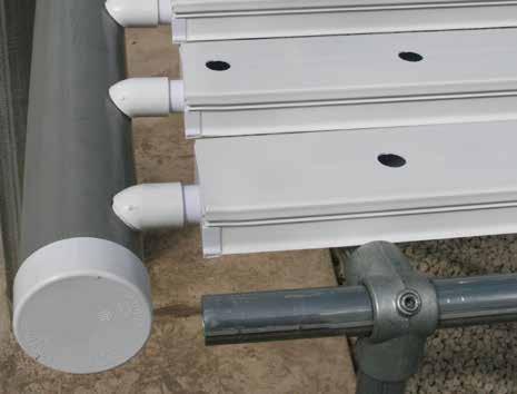
15 Assemble NFT Channels 5 ASSEMBLE THE ' NFT CHANNELS ATTENTION: Attach one end cap with an outlet and one plain end cap to each 12' NFT channel. A Channel (12') B 1. Using the assembled frame as a bench, place one 12' channel (110764) on the cross supports. 2. Take the adhesive (not included additional purchase required) and attach the plain end cap (no outlet ) to the channel end that is resting on the high side of the support frame. This is the side with the 36" legs. Be sure to coat the end of the channel with adhesive before you install the end cap. See photos A & B. Also, apply adhesive to the connection on the inside of the channel. See photo E. Repeat for all 12' channels. C D 3. At the other end of the channel, install the end cap (with outlet). Coat the end of the channel with adhesive before you install the end cap. See photos C & D. Also, apply adhesive to the connection on the inside of the channel. See photo E. Repeat for all 12' channels. Apply adhesive in a well-ventilated area. Read the container information for additional precautions. 4. Carefully flip all 12' channels over so the bottom is facing up. Apply adhesive along the edges to secure and seal end caps to each 12' channel. Photo F shows an end cap with an outlet. Secure the plain end caps in the same manner. NOTE: Be sure to coat all edges and seams of the end caps to prevent leaks. E open top-inside channel bottom F 5. Allow the adhesive to dry before moving the channels or testing the system. 6. Finally, apply a thin film of WF6990 pvc cement around the end cap outlet and slide a 45 elbow (111045) onto the end cap. Install the fitting with the open end pointing down in the 6:00 o'clock position. See Photos G & H. Repeat to install all elbows. G Open Top of Channel Elbow H NOTE: During the assembly, make sure the open end of the elbow is in the 6:00 o'clock position pointing down when the NFT channel is sitting on the frame open top of the channel is up. 7. Continue by assembling and installing the 4" pvc drain tube. Bottom of Channel Bottom of Channel 15
16 6 ATTACH DRAIN TUBE HANGERS Attach Drain Tube Hangers The drain tube hangers support the drain tube assembly along each bank of the NFT channels. Hangers are evenly spaced at 10' along the sidewall of the building. Read all the information in this section and all of Section 7 before you install the hangers. Refer to this section as needed when completing Section 7. Basic installation steps: 1. Prepare the first 10' section of 4' drain tube as instructed in the next section. 2. With assistance, hold the 4" tube in place at the end of the NFT table opposite the pump station. This will become the high end of the drain tube. The 45 elbows of the NFT channels will be fully inserted into the drain tube (without lifting the NFT channel off the frame crossbar) when the tube is properly in place. 3. Next, hook the hanger on the 4" drain tube and place its mounting surface against the sidewall support or stringer board and mark the position. 4. Take the drain tube and hanger to the other end of the frame. This time, lower the 4" drain tube just enough to allow the 45 elbows to be inserted into the hole approximately 1/8" of an inch to prevent leaks. Add the hanger and mark the position on the mounting surface. 5. Stretch and snap a chalk line between the marks. Use the line as a guide to set the drain tube slope of the entire drain tube. NOTE: Building specifics and custom NFT systems may require adjustments to this general set of steps. The main purpose of this procedure is to secure the 4" drain tube assembly and to set the slope to allow proper drainage of the NFT channels. Once the system is operating, recheck the channels at the low end of the drain tube to ensure that there are not leaks around the 45 elbows. 6. Continue with the drain tube assembly steps in Section 7. At the high end of drain tube, fully insert the 45 elbows into the drain holes. At the low end of drain tube, insert the 45 elbows into the drain holes about 1/8" or enough to prevent leaks. Diagrams above show the hanger attached directly to the sidewall supports of the greenhouse. Install a stringer board between sidewall supports that are spaced greater than 10' apart, or when the position of the NFT system does not align with the sidewall supports. Space hangers no further than 10' apart. For all NFT systems, count the number of hangers provided and divide in half. Then evenly space the hanger along the sides of the building to support the 4" drain tube. As noted, maximum hanger spacing is 10' on-center. ATTENTION: All stringer material and fasteners to attach stringers to the building are supplied by the customer. Contact your sales representative for additional information if needed. Treated lumber safe for environments where food is produced is recommended. Other materials such as recycled plastic lumber can also be used. Fasteners to attach the hangers to the stringer board are also supplied by the customer. 16
17 6 ATTACH DRAIN TUBE HANGERS continued Attach Drain Tube Hangers Stringer Customer-supplied fasteners. Sidewall Support 2" x 6" Stringer Hanger Sidewall Support Sidewall spacing in this diagram is 12' on-center. Drain tube hangers are spaced at 10' on-center. Stringer is attached to the sidewall supports to allow for the required spacing of the hangers. ATTENTION: Customer supplies the materials and fasteners to attach stringer to sidewall posts and to secure hangers to the stringer. Diagram shows view of hanger and stringer as installed. Used for illustration purposes. Actual application may differ. ATTENTION: All stringer material and fasteners to attach stringers to the building are supplied by the customer. Contact your sales representative for additional information if needed. Treated lumber safe for environments where food is produced is recommended. Other materials such as recycled plastic lumber can also be used. Fasteners to attach the hangers to the stringer board are also supplied by the customer. 17

 ten foot section of the 4\" drain pipe and mark drain hole positions as shown.")
18 Prepare and Install 4" Drain Tube 7 ASSEMBLE AND INSTALL 4" PVC DRAIN TUBE A 4" drain tube runs the length of each assembled NFT support frame at the low (or drain) side of the frame. This tube directs the nutrient solution from each NFT channel back to the reservoir. Each 10' x 12' square of the frame supports 15 twelve foot NFT channels. (See diagrams below and on the next page.) Depending on length, drain tube can be fully assembled and then drilled, or each 10' section can be drilled and then attached to the next. To prepare and install this drain tube, complete the following steps. 1. Take one (1) ten foot section of the 4" drain pipe and mark drain hole positions as shown. Begin measuring at plain end of 4" tube. This is the end opposite the bell end where the next section will be connected. Plain end will be capped. With assistance, hold tube up to the first drain channel at the frame end and mark hole position. See all notes in photos below. Variences in frame assembly will require adjustments to dimensions shown. Position 4" drain tube flush with the outside edge of frame pipe. CC2652 8" On-Center Water Flow Verify that the NFT channels near the frame fittings are positioned on the cross pipe. Do not place any NFT channel on top of a fitting. Channel must rest on crossbar. 2. From the first mark, continue marking hole positions 8" on-center. Holes must remain aligned throughout the length of the tube. Add the next tube to complete the first series of 15 holes. Do not glue at this time. Verify that the frame fittings do not interfere with the channel positions. Adjust spacing as needed to achieve a uniform appearance and the best results. Pull all channels forward to the drain tube to verify that drain elbows align with the marks on the tube. Remember: There are 15 channels for each 10' x 12' frame square. See also the diagram on the next page. 8" On-Center approximately 121 1/2" to 122" Sample 10' x 12' frame section showing the positions of the 15 channels. 18

, separate the tubes, and clean to prevent contamination of the")


19 7 ASSEMBLE Prepare and Install 4" Drain Tube AND ATTACH 4" PVC DRAIN TUBE continued 3. After all holes are marked, drill the drain holes in the tube using a 1-3/8" hole saw and a drill. Exercise caution during the drilling to prevent injuries and damage to the drain tube. 4. Once all holes are drilled, mark each pipe at the joint (so they can be realigned when glued), separate the tubes, and clean to prevent contamination of the nutrient solution when the system is fully operational. 5. Before continuing with Step 6, return to Section 6 and complete the hanger installation steps. 6. Apply WF6990 pvc cement, realign the marks and drain holes, and connect the sections of prepared drain tube. 7. Repeat these steps to prepare, clean, and glue the remaining drain tubes. Prepare and assemble in 10' and 20' sections for easier handling. Set the assembled drain tube in place after preparation to maintain hole alignment. High end of drain tube. Water flow to pump station 166P144 Mark the 4" tube as needed. Remember to keep all marks aligned. Take an 1-3/8" hole saw and carefully drill the holes in the tube. Clean all tubes before assembly. ATTENTION: Verify that channels are not resting on the fittings of the support frame. See circled areas in diagram. Glue all 4" pipe joints. 166P120 19

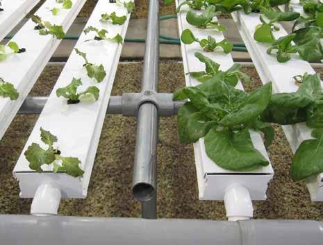
20 7 ASSEMBLE Prepare and Install 4"Drain Tube AND ATTACH 4" PVC DRAIN TUBE continued 8. With the drain assembly installed and all NFT channel elbows inserted in the drain holes, check the slope of the drain tube. Tube should be tight to the underside of the 45 elbows at the high/capped end of the drain tube. At the low or outlet end of the drain tube, the 45 elbows should extend into the drain tube hole just enough to prevent water from running out of the tube. Adjust the drain tube hangers as needed to set the proper slope. 9. Using the remainder of the 4" pvc tube and related fittings, assemble the final sections of drain tubing to connect the table drain tubes to the in-ground tank. See the diagram below (2X) " Drain Tube System Drain Line Supply Lines to Tables 4" Drain Tube 20
21 psi psi Prepare and Install Nutrient Supply Lines 8 INSTALL THE 2" NUTRIENT SUPPLY LINES Each bank of NFT channels is feed by a main 2" pvc supply pipe. This pipe runs from the output side of the main pump, down to ground level, and along the base of the NFT frame. At each 10' frame section, a grommet and adapter are installed in the 2" supply line. A vertical 3/4" feeder tube is then attached to the adapter and runs up the frame pipe and under the NFT channels. Use the diagrams below and on the next page to assemble and attach the nutrient supply lines to each bank of NFT tables. Top View System Drain Line Can be installed on either side. Install 2" pvc and WF1576 elbow to finished grade. Side View WF3516 Connect 2" main supply lines to output from main pump. Flow to NFT Channels WF3516 WF1386 2" PVC Finished Grade 2" PVC WF3516 WF1386 BASIC ASSEMBLY PROCEDURE: 1. Review the diagrams in Sections 8, 9 & 10 before you begin. 2. Layout and connect the 2" main supply lines for each bank of tables according to the diagrams. See next page for details. 3. Drill 7/8" grommet holes in the 2" pvc supply line(s) and install the grommets and adapters. See Section 9 for drilling and installation details. 4. Assemble and attach the 3/4" supply lines. See Section 10 for details. 21
22 8 The Prepare and Install Nutrient Supply Lines INSTALL THE 2" NUTRIENT SUPPLY LINES continued 2" supply lines run at the base of the 36" legs of the frame. This 2" pvc connects to the main plumbing of the pump. Dry fit all connections before final assembly. Install a WF3516 ball valve at the beginning (pump end shown below) and at the end of each run. See the diagrams on the next pages for details. ATTENTION: Do not glue at this time! Joints are glued after drilling the grommet holes and cleaning the pvc. See Procedure 9. Use the WF1984 coupling to connect the individual 10' lengths of 2" pvc tubing. System Drain Line Can be installed on either side. WF3516 Top View WF1984 Coupling 10' Section of 2" PVC Pump End WF1984 Coupling 10' Section of 2" PVC Basic Assembly Steps for 2" PVC Line: 1. Place individual 10' sections along the base of the 36" frame legs. 2. Loosely connect the sections using the WF1984 couplings. 3. Mark the grommet and adapter locations at each 36" leg pipe except the 36" leg pipes each end. 4. Continue with the steps noted in Section 9. WF
23 8 Prepare and Install Nutrient Supply Lines INSTALL THE NUTRIENT SUPPLY LINES continued ATTENTION: Secure the 3/4" tubing to the table frame using the plastic ties. Install approximately every 16" or so. 10' x 12' Frame Section Pump End Plug White Tubing (represented by a black line for clarity) WF3516 Ball Valve 2" PVC Grommet & Adapter Flow 2" PVC Main Supply Line Position the 2" pvc tube against the frame legs Grommet & Adapter NOTE: During the assembly, allow enough length for the vertical 3/4" line to reach the frame fitting. This will allow the 3/4" horizontal tube to be secured to the frame using plastic ties. This line shorter in the diagram to better show the connections. Flow Top View 2" PVC WF1386 Tee See Above Position the 2" pvc tube against the frame legs. 2" PVC Main Supply Lines 23
24 8 ATTENTION: Prepare and Install Nutrient Supply Lines INSTALL THE NUTRIENT SUPPLY LINES continued 10' x 12' Frame Section Interior next to frame section at pump end. Secure the 3/4" tubing to the table frame using the plastic ties. Install approximately every 16" or so Grommet & Adapter White 3/4" Tubing (represented by a black line for clarity) 2" PVC Main Supply Line Flow Position the 2" pvc tube against the frame legs Grommet & Adapter 2" PVC 2" PVC NOTE: During the assembly, allow enough length for the vertical 3/4" line to reach the frame fitting. This will allow the 3/4" horizontal tube to be secured to the frame using plastic ties. This line shorter in the diagram to better show the connections. Flow Top View See previous page for this section. See Above Position the 2" pvc tube against the frame legs. 2" PVC Main Supply Lines 24
25 Prepare and Install Nutrient Supply Lines 8 INSTALL THE NUTRIENT SUPPLY LINES continued 10' x 12' Frame Section Opposite Pump End ATTENTION: Secure the 3/4" tubing to the table frame using the plastic ties. Install approximately every 16" or so White Tubing (represented by a black line for clarity) Grommet & Adapter 2" PVC WF3516 Ball Valve 2" PVC Main Supply Line Flow Top View See Above 2" PVC Main Supply Lines Position the 2" pvc tube against the frame legs. 25


. 3. Disassemble the 2\" supply line and clean the tube to remove the shavings. 4.")

26 2" Supply Line Installation Details 9 2" SUPPLY LINE INSTALLATION DETAILS PVC 7/8" Forstner Bit required. Additional purchase required. Use only a Forstner bit to drill this hole. Other hole saws and bits may cause the grommet and adapter to leak. Complete these steps to install the grommets and adapters. 1. Install grommets and adapters in the 2" pvc supply line at each 36" frame leg except those at each end of the frame. Use the diagrams on the previous three (3) pages to determine the positions of all grommets and adapters if needed. 2. After marking the 2" tube, drill a 7/8" hole at each position using the 7/8" Forstner bit (required). 3. Disassemble the 2" supply line and clean the tube to remove the shavings. 4. Take one of the prepared sections of pvc and install a grommet in the hole. 5. Take one adapter and carefully press it into the grommet. Wet the adapter for easier installation. Use a stiff piece of flat stock if needed to press the adapter into place. Do not pound into place! 6. Repeat the steps to install grommets and adapters into the remaining holes in the 2" pvc. 7. Reassemble each run of pvc pipe. Use the WF1984 couplers and WF6990 cement to secure the joints. 8. Continue with the installation of the 3/4" supply lines, fittings, and valves. 26


27 10 3/4" TUBE INSTALLATION DETAILS Required parts and tools: /4" Elbow /4" White PE Tubing Ratchet Clamps AC2804 In-Line Valves 3/4" Tube Installation Details /4" Tee /4" Plug Tube Cutter (included) Large Adjustable Pliers Use a pair of pliers to gently lock the clamp in place. C A B B Open B D " PVC Main Supply Line Closed 3/4" Riser 3/4" hose connected to grommet and adapter. Install at each 36" leg between the end legs of the frame. 3/4" hose connected to AC2804 in-line valve. Install one valve in each riser. Make sure the clamps do not interfere with valve operation. A C D E 2" PVC 3/4" hose connected to elbow. Install at the top of each riser except at pump end. 3/4" hose connected to AC2804 inline valve. Install at the end of each horizontal supply line. Verify that all fittings are fully inserted into the 3/4" tubing. Use a hair dryer to heat the tubing for easier installation. Do not overheat! 3/4" hose connected to tee fitting. Install at top of riser at pump end only. Cap with plug. Pump End of Frame E Locate tee fittings and plugs at the frame end legs pump end only. 27


28 1/8" Supply Tube Installation Details 11 1/8" SUPPLY TUBE INSTALLATION DETAILS Required parts and tools: Punch UV White Micro Tubing Drill and 3/16" Drill Bit mm Tee Tape Measure and Marker slide lid 1. Set lids on channels so holes are staggered. NOTE: Be sure to drill the 3/16" holes at the correct end of each lid to maintain staggered hole pattern. 2. Mark hole locations for the 1/8" supply tubes. Space holes approximately 2-1/2" to 3" apart so hoses are near the edge of the channel. 3. To prevent shavings from dropping into the channel, slide lid out over the end of the channel (or set lid off to the side) and drill two 3/16" holes in the lid. 4. Remove debris and slide lid into position on channel. Slide channel to expose the 3/4" white supply line. Take the mm punch and punch a hole in the 3/4" line at each channel position. 5. Verify that channels and holes remain aligned as holes are punched. 6. Slide one channel back into position and place the drain elbow in the drain hole of the 4" drain tube to lock channel in place. 7. Cut a 12" supply tube from the poly tubing and verify that the tube is the desired length. 8. Cut another tube to match the first. Approximately 2' of tubing is provided for each NFT channel. 9. Take one tee fitting and gently twist a hose onto each threaded end of the fitting. 10. Gently grip the center portion of the hose and fitting assembly with a clean set of pliers. 28


29 1/8" Supply Tube Installation Details 11 1/8" SUPPLY TUBE INSTALLATION DETAILS continued 11. Press the barb end into the hole of the 3/4" supply tube. 12. Once the tee is firmly installed, gently pull back on the tee to seat it in the hole. Do not pull the barb out of the 3/4" tube! 13. Take the free end of each 1/8" tube and cut it at an angle to easily slide tube into the lid. NOTE: Use a pair of side cutters (shown) or the tube cutter included with this system. 14. Slide the tubes into the channel lid to check final fit. 15. Repeat the steps to cut tubing for the remaining channels and assemble according to the previous steps. 16. After installing all 1/8" supply tubes, verify that all channels are in position on the frame with the drain elbows inserted in the 4" drain tube. 29


30 12 INSTALL TABLE FRAME END CAPS WF6715 Install Table Frame End Caps The WF6715 end caps are provided to cap the open ends of all frame pipe. These caps help to prevent injury when working around the NFT system. Additionally, the end caps keep insects out of the open pipes. After the entire system is assembled, return to all open pipes and slide a cap into position. WF6715 End Cap Frame 30
31 Layout and Frame Section : Commercial NFT System (30' x 48' Greenhouse) Use the diagrams on this page to layout and assemble the support frame for the NFT channels WALKWAY 48 approx. 32 1/2' to 33' (48) GT50 Channels 4 WALKWAY 12 PUMP AREA 8' - 9' 166P P P P120 approx. 32 1/2' to 33' 166P P P (48) GT50 Channels 12 12' NFT System Layout Diagram Support Frame for NFT Channels *ATTENTION: Length of assembled NFT support frame (above) may vary depending on assembly technique and minor differences in overall pipe and fitting dimensions. 31
32 Layout and Frame Section : Commercial NFT System (30' x 60' Greenhouse) Use the diagrams on this page to layout and assemble the support frame for the NFT channels. *ATTENTION: Length of assembled NFT support frame (below) may vary depending on assembly technique and minor differences in overall pipe and fitting dimensions. 60 approx. 45' 12 (66) GT50 Channels 12 NFT System Layout Diagram 30 6 WALKWAY 4 WALKWAY PUMP AREA 8' - 9' 12 (66) GT50 Channels 12 Support Frame for NFT Channels 166P P approx. 45' 166P P P P P048 12' 32
33 Layout and Frame Section : Commercial NFT System (30' x 72' Greenhouse) Use the diagrams on this page to layout and assemble the support frame for the NFT channels. *ATTENTION: Length of assembled NFT support frame (below) may vary depending on assembly technique and minor differences in overall pipe and fitting dimensions. 72 approx. 57' 12 (84) GT50 Channels 12 NFT System Layout Diagram 30 6 WALKWAY 4 WALKWAY PUMP AREA 8' - 9' 12 (84) GT50 Channels P P P072 Support Frame for NFT Channels 166P P120 approx. 57' 166P072 12' 33
34 Layout and Frame Section : Commercial NFT System (30' x 84' Greenhouse) Use the diagrams on this page to layout and assemble the support frame for the NFT channels. *ATTENTION: Length of assembled NFT support frame (below) may vary depending on assembly technique and minor differences in overall pipe and fitting dimensions. 84 approx. 69' 12 (102) GT50 Channels 12 NFT System Layout Diagram 30 6 WALKWAY 4 WALKWAY PUMP AREA 8' - 9' 12 (102) GT50 Channels P P P P P P096 Support Frame for NFT Channels approx. 69' 12' 34
35 Layout and Frame Section : Commercial NFT System (30' x 96' Greenhouse) Use the diagrams on this page to layout and assemble the support frame for the NFT channels. 96 *ATTENTION: Length of assembled NFT support frame (below) may vary depending on assembly technique and minor differences in overall pipe and fitting dimensions. approx. 81' 12 (120) GT50 Channels WALKWAY 4 WALKWAY PUMP AREA 8' - 9' 12 (120) GT50 Channels 12 NFT System Layout Diagram 166P P P P120 approx. 81' 12' Support Frame for NFT Channels 35
36 Layout and Frame Section : Commercial NFT System (30' x 132' Greenhouse) Use the diagrams on this page to layout and assemble the support frame for the NFT channels. *ATTENTION: Length of assembled NFT support frame (below) may vary depending on assembly technique and minor differences in overall pipe and fitting dimensions. 132 approx. 118' 12 (174) GT50 Channels WALKWAY 4 WALKWAY (174) GT50 Channels 12 PUMP AREA Approx. 8' NFT System Layout Diagram 166P P P P P P072 approx. 118' 12' Support Frame for NFT Channels 36


37 Additional Photos for Reference 37

 Fertigation System Fertigation System back side of the mounting panel.")
38 FLOW Additional Photo: Sample Fertigation System FERTIGATION SYSTEM If your Grow-Tek Commercial NFT System includes a fertigation system, consult the fertigation information to properly connect it. These photos show a sample NFT system that also includes a fertigation system. Additional pvc tubing and fittings, as well as a support frame for the fertigation system, are needed. Consult your sales representative for additional information and details. (Actual NFT system may differ from what is shown.) Fertigation System Fertigation System back side of the mounting panel. Supply Line to Fertigation System IN OUT FLOW Fertigation System Supply Line Return Line from Fertigation System. Return Line treated solution back to tank. 38
39 PAGE RESERVED FOR CUSTOMER NOTES AND RECORDS 39
Grow-Tek Commercial NFT System*
 Grow-Tek Commercial NFT System* Designed to grow healthy plants without soil using mineral-nutrient solutions. 2018 FarmTek All Rights Reserved. Reproduction is prohibited without permission. 113516 Commercial
HydroCycle Commercial NFT Systems
 HydroCycle Commercial NFT Systems Designed to grow healthy plants without soil using mineral-nutrient solutions. 2018 Growers Supply All Rights Reserved. Reproduction is prohibited without permission.
HydroCycle Vertical NFT Lettuce & Herb Systems
 HydroCycle Vertical NFT Lettuce & Herb Systems 115162 Light Kit 2016 Growers Supply All Rights Reserved. Reproduction is prohibited without permission. 1 Important Information READ THIS DOCUMENT BEFORE
Aquaponics System IV*
 112666 Aquaponics System IV* A balance between hydroponic vegetable production and fish rearing, GS Series I Aquaponics Systems allow you to produce high-quality produce and fish through the process of
GrowSpan Series 500 Twin-Wall Polycarbonate
 GrowSpan Series 500 Twin-Wall Polycarbonate 1 End Frame size, doors, and panel layout shown above may differ from actual frame. Photo is used for illustration only. 2018 Growers Supply All Rights Reserved.
Evaporative Cooling System End Feed
 Evaporative Cooling System End Feed Straight End Feed 10' to 30' Installation Guide 2017 FarmTek All Rights Reserved. Reproduction is prohibited without permission. *Actual system and pump may differ.
FodderPro 3.0 Commercial Feed Systems
 FodderPro 3.0 Commercial Feed Systems 112657 "...grow your own nutrient-rich fodder..." 18 FarmTek All Rights Reserved. Reproduction is prohibited without permission. Revision date: 09.21.18 *Actual system
HydroCycle Aquaponic Systems
 HydroCycle Aquaponic Systems 2018 Growers Supply All Rights Reserved. Reproduction is prohibited without permission. 115295 AQUAPONIC SYSTEM I *Actual system may differ from example shown. Revision date:
Aquaponics System I*
 112663 Aquaponics System I* A balance between hydroponic vegetable production and fish rearing, GS Series I Aquaponics Systems allow you to produce high-quality produce and fish through the process of
GrowSpan Series 500 Corrugated Polycarbonate 1 End
 GrowSpan Series 500 Corrugated Polycarbonate 1 End Frame size, panel layout, and panel type shown above may differ from actual frame. Photo is used for illustration only. 2018 Growers Supply All Rights
YOUR SPLASH PAD RESOURCE
 1 Index Permits & Inspections Material List Warnings Splash Pad Types Pre-Site Grading Plumbing Schematic Pressure Testing Concrete Preparation and Pour Housing/Nozzle Installation Above Ground Water Feature
Liner Replacement Instructions:
 Liner Replacement Instructions: Before beginning the replacement procedure... Be sure to disconnect electrical service to all of your electrical components of the pool. Use extreme caution when working
DETAIL INSTRUCTION No. 1
 BEFORE BEGINNING INSTALLATION, PLEASE READ THROUGH ALL INSTRUCTIONS. Uncrate shipment and check against packing list to insure all materials are included before beginning installation. If any discrepencies
YELLOW - Evaporative Cooling Wall
 Series 500 Greenhouse Kit w/blackout System, Ventilation & Evaporative Cooling YELLOW - Evaporative Cooling Wall 2017 Growers Supply All Rights Reserved. Reproduction is prohibited without permission.
PV Mounting System 2703 SERIES 200 UL GROUND MOUNT SYSTEM. SnapNrack Residential PV Mounting Systems Code Compliant Installation Manual
 PV Mounting System 2703 SERIES 200 UL GROUND MOUNT SYSTEM SnapNrack Residential PV Mounting Systems Code Compliant Installation Manual Series 200 UL Introduction Series 200 UL Introduction SnapNrack Series
GrowSpan Series 2000 Steel End Frame Kits
 GrowSpan Series 2000 Steel End Frame Kits 20' Wide 2017 Farmek All Rights Reserved. Reproduction is prohibited without permission. SK# GK2EW22120B GK2EW22120G 20' Wide (Base Plates) 20' Wide (No Base Plates)
FERTILIZER IRRIGATION EQUIPMENT LTD. SERIES 6000 APPLICATIONS
 IRRIGATION EQUIPMENT LTD. FERTILIZER T A N K S SERIES 6000 APPLICATIONS Designed specifically for fertigation in agriculture Simple, efficient and trouble free operation. Standard models apply fertilizer
Modular Coldroom Installation Manual
 Modular Coldroom Installation Manual May 2005 Disclaimer: The information contained in this installation guide is provided "as is". Bromic Pty Ltd does not warrant the accuracy, adequacy or completeness
Building a Simple At-home Aquaponics System
 Southern Regional Aquaculture Center SRAC Publication No. 5010 August 2016 PR VI Building a Simple At-home Aquaponics System Matthew Recsetar and Anita Kelly 1 Many people are becoming concerned about
B500-VRC / B600-VRC SERIES INSTRUCTIONS DETAILS RS-500-VRC INSTALLATION
 B500-VRC / B600-VRC SERIES INSTRUCTIONS DETAILS RS-500-VRC INSTALLATION SINGLE WALL VAPOR VENT / TRANSITION SUMPS This document contains specialized instructions for installing the RS-500-VRC Structural
INSTALLATION MANUAL. B-710/760 H20 SERIES MODULAR UST to AST TRANSITION SUMP
 INSTALLATION MANUAL B-710/760 H20 SERIES MODULAR UST to AST TRANSITION SUMP H20-RATED B-710 WITH 2 RISERS, RACK SYSTEM AND BOLLARDS B-710 SPLIT LID TRANSITION SUMP SHOWN WITH H20-RATED DIAMOND PLATE LID
In-Wall Slide-out OEM INSTALLATION MANUAL
 In-Wall Slide-out OEM INSTALLATION MANUAL TABLE OF CONTENTS System and Safety Information 2 In-Wall Slide-Out Chassis Specification 3 6.1.1 Slide-Out Configurations 3 In-Wall Slide-Outs 3 Recommended Wall
BioPrism Solid Surface
 Please read all instructions before installing products. STORAGE & HANDLING: Check for damage that may have occurred during transit. Keep receptor flat on pallet, as it was shipped, until ready to install.
Installation Manual. Read the complete installation manual and Owners Manual before beginning the installation.
 Installation Manual Read the complete installation manual and Owners Manual before beginning the installation. 1. Sizing the System Size the system using the Simplified Sizing Guide For Solar Pool Heaters.
FreeStyle Linear Drain with Full Mortar Bed Adapter Kit
 FreeStyle Linear Drain with Full Mortar Bed Adapter Kit U.S. Patent No. 8,474,068 Patents Pending: Canada & EP Publication No. 2354339 Discard Linear Drain installation instructions and refer to these
B-500 / B-600 SERIES
 B-500 / B-600 SERIES VAPOR VENT TRANSITION INSTALLATION GUIDE SINGLE WALL VENT TRANSITION SUMPS B-500 VENT TRANSITION SINGLEWALL SERIES SHOWN WITH WATERSPLASH LID, AND SUPPORT FOR 5 VENT LINES. B-500 SINGLEWALL
READ THIS MANUAL CAREFULLY BEFORE ASSEMBLY, TESTING & OPERATING
 The Operator must thoroughly read and understand this manual before operating the dust collector or commencing any servicing. Care should be taken to follow all safety rules and warning instructions. READ
Installation Instructions
 Installation Instructions Thank you for choosing the Synergy Reef Shadow Overflow. Please note that this is a Do-It-Yourself project and can be installed in either glass or acrylic aquariums. Always keep
RIGID SOLAR INSTALLATION MANUAL
 RIGID SOLAR INSTALLATION MANUAL Sunlover Heating Factory 5, 9 Jersey Road Bayswater VIC 3153 T: 03 9720 2133 F: 03 9720 3266 New South Wales 2/20-22 Foundry Road Seven Hills, NSW 2147 T: 02 9838 0000 F:
FITNESS PLAYGROUND ITEM NO: 8010
 FITNESS PLAYGROUND ITEM NO: 8010 OWNER S MANUAL CAUTION: This unit is designed to be used safely by up to 4 children between the ages of 3 years to 8 years old with a maximum weight of 100 pounds (45.4
FS-DUO. Wastewater Flow Distributor Technical Data. Submittal Special Precautions Specifications Installation. (62.2 cm) (62.2 cm)
 (62.2 cm)") Wastewater Flow Distributor Technical Data Submittal Special Precautions Specifications Installation 24½" (62.2 cm) 12½" (31.8 cm) 24½" (62.2 cm) (30.5 cm) SUBMITTAL STANDARD: 4" plain end inlet/outlet
Wastewater Flow Distributor Technical Data Submittal Special Precautions Specifications Installation 24½" (62.2 cm) 12½" (31.8 cm) 24½" (62.2 cm) (30.5 cm) SUBMITTAL STANDARD: 4" plain end inlet/outlet
INSTALLATION INSTRUCTIONS MODEL THE CONTRACTOR SUMP BUDDY
 www.burcam.com 2190 Dagenais Blvd. West TEL: 514.337.4415 LAVAL (QUEBEC) FAX: 514.337.4029 CANADA H7L 5X9 info@burcam.com Your pump has been carefully packaged at the factory to prevent damage during shipping.
6x5. Assembly Manual CAUTION. Sharp Edges PATENTS ARE PENDING. Building Dimensions. Approximate Size. Storage Area. Interior Dimensions
 Assembly Manual 6x5 PATENTS ARE PENDING Building Dimensions Approximate Size Storage Area Exterior Dimensions Interior Dimensions Roof Edge to Roof Edge Wall to Wall Sq. Ft. Cu. Ft. Width Depth Height
INSTALLATION GUIDE. 4-Post Lift. Model United States. United Arab Emirates. Egypt.
 4-Post Lift INSTALLATION GUIDE United States 17779 Main Street Suite C Irvine, CA 92614 USA Tel: +1(949) 333-3800 Fax: +1(949) 333-3804 United Arab Emirates Model 46614 P.O. Box 121971 Saif Zone A2-032
SANITARY WASTE AND VENT PIPING
 SECTION 15420 - SANITARY WASTE AND VENT PIPING PART 1 GENERAL 1.01 RELATED DOCUMENTS A. Drawings and general provisions of the Contract, including General and Supplementary Conditions and Division 1 Specification
GGI-750. Gravity Grease Interceptor Technical Data. Submittal Special Precautions Specifications Installation
 Gravity Grease Technical Data Submittal Special Precautions Specifications Installation 75" 81" (205.7 (94.0 cm) 19½" 20" (50.8 (49.5 cm) 21½" 20" (50.8 (54.6 cm) 76½" (194.3 cm) 56½" 57" (144.8 (143.5
PATENTS ARE PENDING. Building Dimensions. Exterior Dimensions Roof Edge to Roof Edge
 Assembly Manual 8x5 PATENTS ARE PENDING Approximate Size 7980303 Storage Area Building Dimensions Exterior Dimensions Roof Edge to Roof Edge Interior Dimensions Wall to Wall Sq. Ft. Cu. Ft. Width Depth
SV24. Submittal Special Precautions Specifications Installation. 12½" (31.8 cm) 12½" (31.8 cm) 12" (30.5 cm) 12" (30.5 cm) 12" (30.
 12½ (31.8 cm) 12 (30.5 cm) 12 (30.5 cm) 12 (30.") Wastewater Sampling Port Technical Data Submittal Special Precautions Specifications Installation 16½" (31.8 (41.9 cm) 8" (20.3 cm) -L -O SUBMITTAL STANDARD: 4" plain end inlet/outlet Highway traffic load
Wastewater Sampling Port Technical Data Submittal Special Precautions Specifications Installation 16½" (31.8 (41.9 cm) 8" (20.3 cm) -L -O SUBMITTAL STANDARD: 4" plain end inlet/outlet Highway traffic load
Multi-Piece EasyStep Product Installation Instructions
 Tools/materials you might need for proper installation 6D galvanized screws caulking gun shims tape measure 1/8 drill bit Phillips screw driver cardboard china marker (or grease pencil) furring strips
Multi-Piece EasyStep Product Installation Instructions
 Tools/materials you might need for proper installation 6D galvanized screws 100% silicone caulking (See specific caulking recommendations) caulking gun shims tape measure 1/8 drill bit Phillips screw driver
Installation Instructions
 Installation Instructions Flue Gas System Basic Kit GA-K - Chimney Flue Gas System for GB125 Oil Condensing Boiler For trained and certified installers Please read carefully prior to installation. 6 720
Important: Before You Start
 Advantage ICF System Advantage ICF System TM Field Guide Important: Before You Start Does Your Building Inspector Know You Are Building with the Advantage ICF System? You are required to check with your
1 PVC or ABS drain with strainer
 Patents Pending ProBase II Single-Slope Shower Base and Kit CONTENTS 1. General Information...1 2. Materials...1 3. Planning...2 4. Preparation...3 5. Layout...3 6. Install Base and Shims...4 7. Install
MEGA-COOL. Evaporative Cooling Systems. Hired-Hand MFG., INC. PO Box 99 Bremen, Alabama Manual Part No Rev 1-08
 MEGA-COOL Evaporative Cooling Systems Hired-Hand MFG., INC. PO Box 99 Bremen, Alabama 35033 Manual Part No. 4801-5120 Rev 1-08 Limited Warranty All products are warranted to be free from defects in material
PATENTS ARE PENDING. Building Dimensions. Exterior Dimensions Roof Edge to Roof Edge
 Assembly Manual 8x9 PATENTS ARE PENDING Approximate Size 7640303 Storage Area Building Dimensions Exterior Dimensions Roof Edge to Roof Edge Interior Dimensions Wall to Wall Sq. Ft. Cu. Ft. Width Depth
Chapter 7. Roof Framing
 Chapter 7. Roof Framing 7.1 ROOFING PREP WORK 7.2 INSTALLING ROOF TRUSSES 7.3 INSTALLING PORCH TRUSSES 7.4 SHEATHING ROOF 7.5 INSTALLING SUB-FASCIA 7.6 BUILDING AND INSTALLING SCUTTLE BOX 7.7 INSTALLING
HALSEY TAYLOR OWNERS MANUAL Classic TM Series Barrier-Free Water Coolers Refrigerated Fountains with Back Panel
 HALSEY TAYLOR OWNERS MANUAL Classic TM Series BarrierFree Water Coolers Refrigerated Fountains with Back Panel Figure HTERQ Figure HTSRQ Figure 3 HTSERQ Figure HTESRQ Figure 3 Model HTERQ HTSRQ HTSERQ
TYPICAL INSTALLATION INSTRUCTIONS
 TYPICAL INSTALLATION INSTRUCTIONS Environment One Grinder Pump Feature Identification 1. Grinder Pump Basin High density polyethylene (HDPE) 2. Accessway Cover Painted Steel 3. Electrical Quick Disconnect
STEP UP SHOWER BASE INSTALLATION GUIDE FOR TIMBER AND CONCRETE FLOORS
 GUIDE FOR TIMBER AND CONCRETE FLOORS EDITION: APRIL 2016 IMPORTANT: This guide is for the installation of a Step Up shower base on a timber or concrete floor. If you require a walk in (flush with floor)
Hydroponic Lettuce Rack DIY Manual
 Report # SFCC-0001 Hydroponic Lettuce Rack DIY Manual By Daniel Spillers & Adam Cohen May 25, 2016 Version 1.0 1 May 25, 2016 Version 1.0 2 About the Authors Daniel Spillers I took up a liking to gardening
Fiberglass Dispenser Sump
 Fiberglass Dispenser Sump Large Mouth LMM-XXXX-X models Single Wall and Double Wall Installation Instructions Franklin Fueling Systems 3760 Marsh Rd. Madison, WI 53718 USA Tel: +1 608 838 8786 800 225
GGI-750. Gravity Grease Interceptor Technical Data. Submittal Special Precautions Specifications Installation
 Gravity Grease Technical Data Submittal Special Precautions Specifications Installation 75" 81" (205.7 (94.0 cm) 19½" 20" (50.8 (49.5 cm) 21½" 20" (50.8 (54.6 cm) 76½" (194.3 cm) 56½" 57" (144.8 (143.5
Pittsburgh Corning ProVantage Glass Block Installation System Assembly Instructions
 Pittsburgh Corning ProVantage Glass Block Installation System Assembly Instructions Introduction: The ProVantage Glass Block Installation System is the easiest way to install Pittsburgh Corning Premiere
FS-TRIO. Wastewater Flow Distributor Technical Data. Submittal Special Precautions Specifications Installation. (62.2 cm) (62.
 (62.") Wastewater Flow Distributor Technical Data Submittal Special Precautions Specifications Installation 24½" (62.2 cm) 12½" (31.8 cm) 24½" (62.2 cm) (30.5 cm) SUBMITTAL STANDARD: 4" plain end inlet/outlet
Wastewater Flow Distributor Technical Data Submittal Special Precautions Specifications Installation 24½" (62.2 cm) 12½" (31.8 cm) 24½" (62.2 cm) (30.5 cm) SUBMITTAL STANDARD: 4" plain end inlet/outlet
Installation Guide. Rain Screen Panel System
 Installation Guide Rain Screen Panel System Main Office 6860 South Abbott Road Orchard Park, New York 14127 tel 716.649.7490 toll free 1.888.214.3655 www.bostonvalley.com General Inquiries info@bostonvalley.com
How To Construct a Ferro Cement Tank
 How To Construct a Ferro Cement Tank Be Advised The following power point presentation assumes that individuals using it to construct ferro-cement tanks have a basic knowledge of geometry and calculating
6032 SH 3P Residential Shower Installation Instructions Gelcoat & Solid Surface Bathware
 Tools/materials you might need for proper installation 6D galvanized screws 100% silicone caulking caulking gun acrylic latex caulk shims tape measure 1/8 drill bit Phillips screw driver cardboard china
LK Wallbox UNI Push X16 V2
 LK Wallbox UNI Push X16 V2 Intended only for LK PE-X Universal Pipe. See: http://www.lksystems.se/en/products/lkuniversal/products/pipes/pe-x/ PE-X pipe-in-pipe system, including components according to
SECTION STORM UTILITY DRAINAGE PIPING PART 1 - GENERAL 1.1 SUMMARY 1.2 SUBMITTALS 1.3 PROJECT CONDITIONS
 SECTION 334100 - STORM UTILITY DRAINAGE PIPING PART 1 - GENERAL 1.1 SUMMARY Section Includes: 1. Pipe and fittings. 2. Drain Basin. 3. De-chlorination tablet feeder. 4. Non-pressure transition couplings.
N Scale Double Track Lift Bridge v1.2
 N Scale Double Track Lift Bridge v1.2 3.25"W x 16"L x 7.5"H Plus two 5" long approach bridges Instructions for assembly of the Lift Bridge Included in this kit: Instructions and part diagrams 138ea. 1/16"
SECTION FACILITY SANITARY SEWERS
 SECTION 22 13 13 FACILITY SANITARY SEWERS PART 1 - GENERAL 1.1 RELATED DOCUMENTS A. Drawings and general provisions of the Contract, including General and Supplementary Conditions and Division 01 Specification
SENTINEL BARRIER - GENERAL INSTALLATION GUIDELINES
 SENTINEL BARRIER - GENERAL INSTALLATION GUIDELINES Safety Precautions in the Excavation of a Sentinel Wedge take all necessary steps to make sure the pit is secured. Follow all OSHA requirements for digging
adjustable fusion shower pan surface mounted on subfloor installation guide
 a a) Wall b) Tile c) Adjustable Shower Pan d) Liquid Membrane e) Crack Isolation Tape f) Cement Board g) Subfloor h) Joists b d c f h g e adjustable fusion shower pan surface mounted on subfloor www.trendingaccessibility.com
SECTION COMMON WORK RESULTS FOR FIRE SUPPRESSION
 SECTION 21 05 00 COMMON WORK RESULTS FOR FIRE SUPPRESSION PART 1 - GENERAL 1.1 SUMMARY A. This section supplements all sections in this division, including pipe, fittings, valves, and connections for sprinkler
CITY OF MOUNT DORA LIFT STATION CHAINLINK FENCE AND GATE SPECIFICATIONS
 CITY OF MOUNT DORA LIFT STATION CHAINLINK FENCE AND GATE SPECIFICATIONS PART 1 - GENERAL 1.01 SUMMARY A. Section Includes furnishing and installing chain-link fabric fence, gate, and appurtenances. 1.02
NORTHWESTERN UNIVERSITY PROJECT NAME JOB # ISSUED: 03/29/2017
 SECTION 22 1316 - SANITARY WASTE AND VENT PIPING PART 1 - GENERAL 1.1 RELATED DOCUMENTS A. Drawings and general provisions of the Contract, including General and Supplementary Conditions and Division 01
Get Growing NFT 10K Small Business Bundle
 1984 Get Growing NFT 10K Small Business Bundle Contents 1 NFT 10K Inclusions List 2 NFT System Specifications 3 Get Growing 10K - Greenhouse Options 4 Get Growing 10K - Bundle Options 5 NFT System Details
HALSEY TAYLOR OWNERS MANUAL Classic TM Series Barrier-Free Water Coolers Refrigerated Fountains with Back Panel
 HALSEY TAYLOR OWNERS MANUAL Classic TM Series BarrierFree Water Coolers Refrigerated Fountains with Back Panel Figure HTERQ Figure HTSRQ Figure 3 HTSERQ Figure HTESRQ Figure 3 Model HTERQ HTSRQ HTSERQ
MASTERSPEC TECHNICAL SPECIFICATIONS DIVISION 22 PLUMBING
 SECTION 221316 - SANITARY WASTE AND VENT PIPING PART 1 - GENERAL 1.1 SUMMARY A. This Section includes the following soil and waste, sanitary drainage and vent piping inside the building: 1. Pipe, tube,
SECTION 1208 CHAIN LINK FENCING DESCRIPTION
 SECTION 1208 CHAIN LINK FENCING 1208-1 DESCRIPTION This item covers the requirements for furnishing materials and constructing new chain link fences and gates in accordance with the details included herein
INSTALLATION MANUAL MOSER STAINLESS STEEL KITCHEN FAUCET MODEL MANCHESTER
 INSTALLATION MANUAL MOSER STAINLESS STEEL KITCHEN FAUCET MODEL MANCHESTER Thank you for your purchase of a MoSER faucet. With proper care and maintenance, your new faucet will bring you years of trouble
Ubau Flo Shower Element Installation Manual
 Ubau Flo Shower Element Installation Manual The information pertained within this guide is for reference only and does not supersede instructions from other product manufacturers or building codes. Always
SECTION CHAIN LINK FENCES AND GATES (PARK)
") SECTION 02821 CHAIN LINK FENCES AND GATES (PARK) PART I GENERAL 1.1 SECTION INCLUDES A. Installation of chain link fences, and gate units provided by single source including erection accessories, fittings,
SECTION 02821 CHAIN LINK FENCES AND GATES (PARK) PART I GENERAL 1.1 SECTION INCLUDES A. Installation of chain link fences, and gate units provided by single source including erection accessories, fittings,
SOUNDGUARD INSTALLATION MANUAL
 SOUNDGUARD INSTALLATION MANUAL WWW.ROOFSCREEN.COM 831 421 9230 Introduction... 2 This manual... 2 Application... 2 System Overview... 2 Components... 2 Face Panels... 3 Insulation... 3 Perforated Liner
MODULAR ACOUSTIC FENCING INSTALLATION GUIDE
 MODULAR ACOUSTIC FENCING WWW.QUICKBUILTSYSTEMS.COM.AU INSTALLATION GUIDE INTRODUCTION THE QUICKBUILT FENCE SYSTEM IS A SMARTLY DESIGNED MODULAR SYSTEM EASY AND FAST TO INSTALL AND COST EFFECTIVE. // THE
INSTALLATION INSTRUCTIONS FOR ELECTRICAL CONTRACTORS
 INSTALLATION INSTRUCTIONS FOR ELECTRICAL CONTRACTORS Rev. 1.5 1.10.13 Toll free (800) 288-6000 or www.hubbell-wiring.com P a g e 0 IMPORTANT SAFETY INSTRUCTIONS SAVE THESE INSTRUCTIONS WARNING- When using
Daytona Beach Pier Building Renovation Jun 2010
 SECTION 15150 - SANITARY WASTE AND VENT PIPING PART 1 - GENERAL 1.1 RELATED DOCUMENTS A. Drawings and general provisions of the Contract, including General and Supplementary Conditions and Division 1 Specification
BRILLIANT WONDERS LED WATERFALL INSTALLATION INSTRUCTIONS CMP SERIES. Brilliant Wonders LED WATERFALLS
 R BRILLIANT WONDERS LED WATERFALL INSTALLATION INSTRUCTIONS CMP 25677 SERIES Brilliant Wonders LED WATERFALLS TABLE OF CONTENTS 1 Product Overview....2 1.1. Packing List...2 2 Safety.3 3 Installation Guide.....4
A. This Section includes sanitary waste and vent piping inside the building and to locations indicated.
 SECTION 221316 SANITARY WASTE AND VENT PIPING PART 1 - GENERAL 1.1 RELATED DOCUMENTS A. Drawings and general provisions of the Contract, including General and Supplementary Conditions and Division 01 Specification
PREMIER V Bucko Cast In Place
 PREMIER V Bucko Cast In Place 28972 R. Ave Adel, Iowa 50003 800-343-9370 1850 West Adriatic Place Englewood, Colorado 80110 303-935-4679 Visit Monarch Materials Group, Inc. at www.monmatgrp.com Premier
30mm Height Linear Drain Shower Trays
 Installation Instructions 30mm Height Linear Drain Shower Trays 9. Parts Supplied Description Qty Shower Tray Parts Supplied (Fitting Kit) Description Qty Description Qty Shower Drain Base Fix-KST Adhesive
Sump Pump System OEM INSTALLATION MANUAL
 Sump Pump System OEM INSTALLATION MANUAL TABLE OF CONTENTS System and Safety Information 2 Preparation 2 Resources Required 2 Installation 3 Plumbing 3 Electrical Connections 4 Operation 5 System and Safety
SpaVault TM Installation Guide for Bullfrog Spas (7-10 x 7-10 x 38 )
") SpaVault TM Installation Guide for Bullfrog Spas (7-10 x 7-10 x 38 ) WARNING - When unpacking SpaVault, DO NOT discard styrofoam pieces, these are not packaging materials. Step 1 Excavation Important:
SpaVault TM Installation Guide for Bullfrog Spas (7-10 x 7-10 x 38 ) WARNING - When unpacking SpaVault, DO NOT discard styrofoam pieces, these are not packaging materials. Step 1 Excavation Important:
CONSOLIDATED EDISON COMPANY OF NEW YORK, INC. 4 IRVING PLACE NEW YORK, NY DISTRIBUTION ENGINEERING DISTRIBUTION EQUIPMENT
 CONSOLIDATED EDISON COMPANY OF NEW YORK, INC. 4 IRVING PLACE NEW YORK, NY 10003 DISTRIBUTION ENGINEERING DISTRIBUTION EQUIPMENT SPECIFICATION EO-1124 REVISION 3 November 2013 EFFECTIVE DATE November 11,
EXIRA EXPOSED PIPE SHOWER INSTALLATION
 SKU(s): 923583 EXIRA EXPOSED PIPE SHOWER INSTALLATION BEFORE YOU BEGIN We recommend consulting a professional if you are unfamiliar with installing plumbing fixtures. Signature Hardware accepts no liability
DOUBLE CONTAINMENT DESIGN & INSTALLATION GUIDE
 DC-3-0604 Spears Double Containment Systems are engineered for ease of installation and lower associated installation costs. Complete systems include all necessary components - carrier pipe, containment
Valance Installation. For Units with Beam Style Coils
 Valance Installation For Units with Beam Style Coils 1. Before installation of valance units, determine if drapes are to be used, or if any wall construction will protrude into room. If either drapes or
C.R. LAURENCE CO., INC. Intelli-Track SPS. Phase One - Installation Instructions
 Tools and Supplies: C.R. LAURENCE CO., INC. Intelli-Track SPS Phase One - Installation Instructions Ratchet Wrench with 4" Extension 9/16" Open-End Wrench (two required for suspension mounting) 9/16" Hex
Multicell. Vikimatic MultiCell Conduit Systems MULTICELL
 Multicell Vikimatic MultiCell Conduit Systems These guidelines should help you install MultiCell Conduit in the simplest way possible and should be read in their entirety before attempting to install the
Lawn Garden Sprinkler Project
 Lawn Garden Sprinkler Project Name: Date: Description: Use basic plumbing skills and common plumbing materials to construct a lawn/garden sprinkler. General skills used to build this project include measuring,
Multi-Piece Shower with Trench Drain
 INSTALLATION INSTRUCTIONS Multi-Piece Shower with Trench Drain (For models requiring mud set) 1069 This packet includes installation instructions for the Bestbath products shown below. (These instructions
INSTALLATION MANUAL KOCH
 INSTALLATION MANUAL KOCH TECHNICAL SYSTEMS GROUP PRE-FAB ACOUSTICAL/THERMAL PANELS AND ENCLOSURES GEORGE KOCH SONS, LLC TECHNICAL SYSTEMS GROUP 10 South Eleventh Avenue Evansville, Indiana 47744 812-465-9600
SECTION FACILITY STORM DRAINAGE PIPING
 SECTION 22 1413 FACILITY STORM DRAINAGE PIPING PART 1 - GENERAL 1.1 RELATED DOCUMENTS A. Drawings and general provisions of the Contract, including General and Supplementary Conditions and Division 01
WALK-IN SHOWER BASE INSTALLATION GUIDE FOR CONCRETE FLOORS
 WALK-IN SHOWER BASE INSTALLATION GUIDE FOR CONCRETE FLOORS EDITION: APRIL 2016 IMPORTANT: If you require a Walk In shower base for timber floors, please go to our support page at www.hydroblok.com.au IMPORTANT:
Genesis Panel Systems LLC Dura-Max Brick Panel Siding Installation Instructions
 Genesis Panel Systems LLC Dura-Max Brick Panel Siding Installation Instructions Thank you for purchasing the Genesis Dura-Max Brick Panel system for your project. The system allows you to have the look
Se incluyen las instrucciones en español
 Page 1 of 16 Pittsburgh Corning Corporation Pittsburgh, PA 15239 1-800-624-2120 www.pittsburghcorning.com All trademarks and registered trademarks in this brochure are owned and protected by Pittsburgh
A. Piping materials shall bear label, stamp, or other markings of specified testing agency.
 SECTION 221316- PART 1- GENERAL 1.1 SUMMARY A. Section Includes: 1. Pipe, tube, and fittings. 2. Specialty pipe fittings. 1.2 INFORMATIONAL SUBMITTALS A. Field quality-control reports. 1.3 QUALITY ASSURANCE
FORMWORK 66 x 40 x 24 Lithic Freestanding or Alcove Box Bathtub Installation Guidelines. STYLE No. CAUTION: BATHTUB IS EXTREMELY HEAVY
 STYLE No. STYLE No. FMBT6L (With Left Drain) FMBT6R (With Right Drain) CAUTION: BATHTUB IS EXTREMELY HEAVY PACKAGED WEIGHT... 1200 LBS [544.3 KG] DRY WEIGHT... 1050 LBS [476.3 KG] FILLED WEIGHT... 1750