Design Guide Handbook for EN 1996 Design of Masonry Structures
|
|
|
- Elijah Jones
- 6 years ago
- Views:
Transcription
1 Design Guide Handbook for EN 1996 Design of Masonry Structures September 2006 Department for Communities and Local Government: London
2 On 5th May 2006 the responsibilities of the Office of the Deputy Prime Minister (ODPM) transferred to the Department for Communities and Local Government (DCLG) Department for Communities and Local Government Eland House Bressenden Place London SW1E 5DU Telephone: Website: Design Guide Handbook for EN 1996 March 2005 It should be noted that this guidance has been based on Eurocode EN (49). No National Annex was available. Crown Copyright, 2006 Copyright in the typographical arrangement rests with the Crown. This publication, excluding logos, may be reproduced free of charge in any format or medium for research, private study or for internal circulation within an organisation. This is subject to it being reproduced accurately and not used in a misleading context. The material must be acknowledged as Crown copyright and the title of the publication specified. Any other use of the contents of this publication would require a copyright licence. Please apply for a Click-Use Licence for core material at or by writing to the Office of Public Sector Information, Information Policy Team, St Clements House, 2-16 Colegate, Norwich, NR3 1BQ. Fax: or HMSOlicensing@cabinet-office.x.gsi.gov.uk If you require this publication in an alternative format please alternativeformats@communities.gsi.gov.uk DCLG Publications PO Box 236 Wetherby West Yorkshire LS23 7NB Tel: Fax: Textphone: communities@twoten.com or online via the DCLG website: September 2006 Product Code: 06 BD (e)
3 CONTENTS EXECUTIVE SUMMARY 5 BACKGROUND 6 CHAPTER 1 DRAFT EUROCODE 6 HANDBOOK 7 1. Introduction General Scope of Eurocode 6, Parts 1-1; 1-2; 2; and National Annexes The effect of the CEN programme on existing British Standards Structure of this guidance document 10 CHAPTER 2. EN : COMMON RULES FOR REINFORCED AND UNREINFORCED MASONRY STRUCTURES General Basis of design Material properties Durability Structural analysis Ultimate limit state Serviceability limit state Structural Detailing Execution Design examples 26 CHAPTER 3. EN : STRUCTURAL FIRE DESIGN Scope Basic principles and rules Materials Design procedures for obtaining fire resistance of masonry walls Detailing 33
4 CHAPTER 4. EN : SIMPLIFIED CALCULATION METHODS AND SIMPLE RULES FOR MASONRY STRUCTURES General Basis of design Materials Design of unreinforced masonry walls using simplified methods 35 CHAPTER 5 POLICY IMPLICATIONS 37 APPENDIX A List of previous reports, with references, for this project 38 APPENDIX B Project summary 39 APPENDIX C Buro Happold notes on design approach for the design examples 40
5 Executive Summary Executive Summary The overall aim of this project is to encourage a satisfactory level of adoption of EN1996: Design of Masonry Structures within the construction industry during the period that it is coexistent with the UK national codes, particularly BS5628 Use of Masonry. The first output was BRE Report No This contained contents lists for the two document outputs - the Handbook for using Eurocode 6 and the Companion Document to the various parts of Eurocodes 6 and their supporting standards. The second output from this project was BRE Report No , which contained a first draft Design Guide Handbook for EN 1996 Design of Masonry Structures. This report is the third output from this project, and contains a second, revised, draft of the Design Guide Handbook for EN 1996 Design of Masonry Structures. 5
6 Design Guide Handbook for EN 1996 Design of Masonry Structures Background This is the third output from this project: The first output was BRE Report No This contained contents lists for the two document outputs - the Handbook for using Eurocode 6 and the Companion Document to the various parts of Eurocodes 6 and their supporting standards. The second and third were BRE Reports Nos and , which were two documents - draft copies of the Handbook for using Eurocode 6 and the Companion Document to the various parts of Eurocodes 6 and their supporting standards. This report contains a second, revised, draft of the Design Guide Handbook for EN Design of Masonry Structures. 6
7 Draft Eurocode 6 Handbook Draft Eurocode 6 Handbook 1. Introduction 1.1 General In 1975, the Commission of the European Community decided on a programme to eliminate technical obstacles to trade via the harmonisation of technical specifications. Central to this process was the establishment of a set of harmonised technical rules for the design of construction works which would ultimately replace the national codes of practice used in each of the member countries. Responsibility for this programme was later passed on to CEN, in order to provide them with the future status of a European Standard (EN). At the same time, the number of states involved increased to include the members of both the EU and EFTA. The Structural Eurocode programme comprises the following standards, generally consisting of a number of Parts: - EN 1990 Eurocode: Basis of structural design - EN 1991 Eurocode 1: Actions on structures - EN 1992 Eurocode 2: Design of concrete structures - EN 1993 Eurocode 3: Design of steel structures - EN 1994 Eurocode 4: Design of composite steel and concrete structures - EN 1995 Eurocode 5: Design of timber structures - EN 1996 Eurocode 6: Design of masonry structures - EN 1997 Eurocode 7: Geotechnical design - EN 1998 Eurocode 8: Design of structures for earthquake resistance - EN 1999 Eurocode 9: Design of aluminium structures The National Standards implementing the Eurocodes will comprise the full text of the Eurocode (including any annexes), as published by CEN, which may be preceded by a National title page and National foreword, and may be followed by an informative National Annex. The annexes to the full text of the Eurocodes can have two statuses - normative, where they have to be taken as part of the Eurocode, and informative, where their status will be set by each country in their National Annex. 7
8 Design Guide Handbook for EN 1996 Design of Masonry Structures It is a relatively minor point but it should be borne in mind that all CEN documents use a comma to represent the decimal place in a number - e.g. 0,4 is what the UK would typically represent as 0.4. Additionally, all the Eurocodes contain two types of clause: a standard type and a principle. These can be distinguished by the presence of a capital P immediately after the clause number e.g. (1)P is a principle; (2) is not. A principle clause contains the basis on which that section is based, and this may not be deviated from. A clause which contains a principle will include the word shall, while the non-principle clause will contain the word should. 1.2 Scope of Eurocode 6, Parts 1-1; 1-2; 2; and 3 Eurocode 6 consists of four parts: - EN : Common rules for reinforced and unreinforced masonry structures. - EN : Structural fire design. - EN : Design, selection of materials and execution of masonry. - EN : Simplified calculation methods and simple rules for masonry structures. Each of these parts covers a discrete aspect of masonry construction. They are sometimes referred to as Eurocode 6 Part 1-1, Part 1-2, Part 2 and Part EN This Part of Eurocode 6 describes the principles and requirements for safety, serviceability and durability of masonry structures. It is based on the limit state concept used in conjunction with a partial factor method, and is intended that it will replace BS : Structural use of unreinforced masonry and BS : Structural use of reinforced and pre-stressed masonry. For the design of new structures, EN is intended to be used with ENs 1990, 1991, 1992, 1993, 1994, 1995, 1997, 1998 and 1999, as appropriate for the design. EN is intended for use by: - committees drafting standards for structural design and related product, testing and execution standards; - clients (e.g. for the formulation of their specific requirements on reliability levels and durability); - designers and contractors; and - relevant authorities. 8
9 Draft Eurocode 6 Handbook EN EN covers all aspects relating to the structural fire design of masonry EN EN covers the design, selection of materials and execution of masonry. In UK terms, it will be replacing BS : Materials and components, design and workmanship, although it does not have as broad a sweep as that BS and will therefore not replace that document in its entirety EN EN provides a simplified method of calculation and simple rules for masonry structures. In the main, these are based on the approach given in EN , but with simplifications. As a result, the design procedure followed in EN is simpler than that set out in EN , but a design produced following the requirements of Part 3 will provide a less efficient solution - in this context, that means it will use more materials to do the same job. There is one exception to this - internal partition walls - referred to as internal non-load bearing walls - are not referred to in Part 1-1, but they are included in Part National Annexes Each of the Eurocodes gives symbols and alternative methods for which a national value or choice needs to be given; notes under the relevant clauses indicate where national choices may have to be made. These parameters, which are left open for national choice, are known as Nationally Determined Parameters. These are related to safety issues - for which each nation has overall responsibility - and are to be used for the design of buildings and civil engineering works to be constructed in the country concerned. The National Standard implementing each Eurocode and Standard is likely to include a National Annex, following its text, containing all the Nationally Determined Parameters to be used in that country associated with that Eurocode or Standard. However, the National Annex is only allowed to contain information on: - values and/or classes where alternatives are given in the Eurocode, - values to be used where a symbol only is given in the Eurocode, - country specific data (geographical, climatic etc), e.g. snow map, - the procedure to be used where alternative procedures are given in the Eurocode It may also contain: - decisions on the application of informative annexes 9
10 Design Guide Handbook for EN 1996 Design of Masonry Structures - references to non-contradictory complementary information (NCCI) to assist the user to apply the Eurocode. 1.4 The effect of the CEN programme on existing British Standards The various parts of Eurocode 6 will replace all three parts of BS BS ; BS ; and BS with the supporting standards replacing the majority of the current BS standards referred to in these codes of practice. This process will take time, with equivalent standards running in parallel - co-existing - for a defined period before the BS is withdrawn. Clearly, there will be areas where, as a result of the inevitable compromises required when a code or standard is produced to satisfy the needs of many countries, information currently present in the national codes or standards will not be included in these CEN documents. Where this arises, this information will not be lost. Instead, the need for it will be reassessed and, where it is decided that it is needed, it will be retained. The location will depend on the information, but it is expected that one or more of the existing codes and standards will be retained and contain just that material. They will not, however, include any information that conflicts with the Eurocodes Structure of this guidance document This guidance document has been developed with the aim of providing ready access to the various parts of Eurocode 6 needed for the design of masonry, highlighting areas where the design approach differs between a Eurocode and its equivalent BS. As such, it has been drawn up to meet the needs of the designer, or an interested party, coming to the documents for the first time while at the same time being aware of the British Standards which these Eurocodes are intended to replace, at least in part - BS 5628 parts -1 and -2. It is split into three basic sections, each one containing information on one Part of Eurocode 6. The order chosen for the sections to run in is based on their interaction in usage, rather than their formal Eurocode numbering. There is a degree of overlap between some of the parts - for example, Parts 1-1, 1-2 and 3 all include sections on the properties of the materials used. Where this arises, a reference has been made to the provisions in the Part being detailed; where appropriate, a further reference to a more complete Section within one of the other Parts has also been made. 10
11 EN : Common Rules for Reinforced and Unreinforced Masonry Structures 2. EN : Common rules for reinforced and unreinforced masonry structures 2.1 General Section 1: This section of EN covers the scope of Eurocode 6. As such, it makes reference to the other Parts of Eurocode 6 and covers exclusions to Part 1-1. It also includes all the definitions, terms relating to masonry and symbols used in Part Basis of design Section 2: This section covers the basis on which the design must be carried out. The design values of material properties, combinations of actions and the ultimate limit stress condition are included here. As with the current British Standard Codes of Practice, the alternative to following the procedures set out in this part of the Eurocode is to determine the structural properties of masonry by testing. This is allowed, and further information on this approach is given in Annex D (informative) of EN Unlike the earlier pre-normative code - ENV little specific information is given to the designer in this section. Instead, very general principles are laid out and reference is made to other Eurocodes containing the specifics of the general design rules. Like the other Eurocodes, EN is a partial factor design load. As such, it uses partial safety factors applied to both the loads and the material properties in the design process. Partial safety factors are given the name gamma factors as a result of the Greek letter γ being used as their symbol. The subscript M is used to identify the partial safety factor for materials. The design value for a material property is derived by dividing its characteristic value by the relevant partial safety factor, γ M. The characteristic values are obtained from Section 3, while values of the partial safety factor for masonry materials, γ M, for the ultimate limit state are given in a Table contained in the note to clause 2.4.3(1)P and for the serviceability limit state it is found in a note to clause 2.4.4(1). The table in the note to clause 2.4.3(1)P contains ranges of values of γ M for a number of masonry types and items used in masonry construction - among the latter are ancillary components and lintels. As these partial safety factors, γ M, are in notes, they are Nationally Determined Parameters, and guidance on the appropriate values to be used will be included in the UK s National Annex to 1-1, which will follow the EN s text in BS EN , when that is published. 11
12 Design Guide Handbook for EN 1996 Design of Masonry Structures 2.3 Material properties Section 3: This section provides the data on the material properties of the masonry to be used in the design process. Clause 3.1: Masonry units The initial clauses deal with the standards with which the units must comply and their strength, as well as the Groupings of the units. As part of this process, it sets out the criteria which are used to Group the units. These Groupings are used to identify the appropriate equations to be used when determining the properties of the masonry, in compression, shear, and flexure. Basically, the units are placed into one of four Groups which are dependent on a combination of: - the volumes of the holes, - the volume of a single hole, - the minimum thickness in and around holes; and - the combined thickness of the webs and shells, with Table 3.1 containing the requirements for Grouping the units. Clause 3.2 Mortars Clause 3.2 covers mortars and sets out the requirements for the types of mortars that can be used with EN They are: - general purpose mortar; - thin layer mortar; and - lightweight mortar. Clause 3.2 also covers mortar classification. In EN , mortars are classified according to their compressive strength, with the letter M followed by the compressive strength being used to define them e.g. M5 refers to a mortar with a compressive strength of 5.0 N/mm 2. Where a prescriptive mortar is used in the UK, it will be classified according to both its M number and a strength assigned to its prescribed constituents - e.g. a 1: 1: 6 cement: lime: sand, by volume mortar will be described as M4 as it has been assumed that its compressive strength will be 4.0 N/mm 2. A note to clause 3.2.2(1) states that acceptable equivalent mixes, described by the proportion of their constituents, may be ascribed stated M values in a National Annex. As this is contained in a note, any such ascribed value would be a Nationally Determined Parameter. As a result, guidance on their appropriate values will be included in the UK s National Annex to 1-1, which will follow the EN s text in BS EN , when that is published by BSI. 12
13 EN : Common Rules for Reinforced and Unreinforced Masonry Structures It is anticipated that the typical UK mortar designations will be assigned the following M values: BS : 1991 mortar designation EN classification Mortar compressive strength (i) M N/mm 2 (ii) M6 6.0 N/mm 2 (iii) M4 4.0 N/mm 2 (iv) M2 2.0 N/mm 2 It should be noted that, unlike Table 1 of BS , only one set of compressive strengths are stated, so there is no provision to distinguish between laboratory and site derived values. Further guidance is given on the properties of both mortar and concrete infill, as well as reinforcing and pre-stressing steel in Clauses 3.3, 3.4 and 3.5, respectively. Clause 3.6 Mechanical properties of masonry Clause 3.6 covers the derivation of the mechanical properties of the masonry: - Clause deals with the characteristic compressive strength of the masonry; - Clause deals with its characteristic shear strength; - Clause deals with its characteristic flexural strength; and - Clause deals with the characteristic anchorage strength of reinforcement. Clause characteristic compressive strength of the masonry The characteristic compressive strength of masonry other than shell bedded masonry - found in clause can be based on the results of tests carried out in accordance with EN which tests may be carried out for the project or be available from tests previously carried out e.g. a database; the results of the tests should be expressed as a table, or in terms of the following equation: f k = K f b α f m β, where, f k is the characteristic compressive strength of the masonry K is a constant 13
14 Design Guide Handbook for EN 1996 Design of Masonry Structures f b is the normalised mean compressive strength of the masonry unit; and f m is the compressive strength of the mortar. Alternatively, the relationship can be defined by the equations and conditions found in clauses (2) and (3). These two clauses contain equations in which α and β have the values 0.7 and 0.3, respectively; K values, for use in the equations, are also provided in Table 3.3. There are a number of limits put on the compressive strengths of both the units and the mortar, depending on the usage and the combinations of materials used. It is currently anticipated that the approach used in the UK will be the one that uses the K values in combination with the equations. For shell bedded masonry, only the route using the equations is permitted. This approach is quite different from that used in BS , where the compressive strength of the masonry is given in clause 23 and the values are contained in both graphical form - in Figures 1 - and in tabular form - in Tables 2 and modifiers are used to cover some other exceptions such as slender or narrow walls. Clause Characteristic shear strength For the characteristic shear strength of masonry - contained in clause the following equation is used: where: f vk = f vko + 0,4 α d f vko is the characteristic initial shear strength, under zero compressive stress; f vlt is a limit to the value of f vk ; α d is the design compressive stress perpendicular to the shear in the member at the level under consideration, using the appropriate load combination; and f b is the normalized compressive strength of the masonry units for the direction of application of the load on the test specimens being perpendicular to the bed face. The decision on whether to use 0,065f b or f vlt in a country, and the value of f vlt if this option is chosen, is contained in a note, so it is a Nationally Determined Parameter. As a result, guidance on the appropriate method and values will be included in the UK s National Annex to 1-1, which will follow the EN s text in BS EN , when that is published by BSI. While the form of the equation used here is the same as that used BS , the value of the constant is not the same - for example, a value of 0,6 is used for µ in the UK rather than the value of 0,4. 14
15 EN : Common Rules for Reinforced and Unreinforced Masonry Structures Clause Characteristic flexural strength Information on f xk, the characteristic flexural strength of masonry, is contained in clause The first thing to note is that the symbol used to represent the flexural strength having a plane of failure parallel to the bed joints, is f xk1, while f xk2 is used for flexural strength having a plane of failure perpendicular to the bed joints. This symbol is essentially the reverse of the UK s f kx. Tabulated values of the characteristic flexural strength of masonry, both parallel and perpendicular to the bed joints, are contained in a note to clause 3.6.3(3). As they are contained in a note, they are again Nationally Determined Parameters. As a result, guidance on appropriate values to be used will be included in the UK s National Annex to 1-1, which will follow the EN s text in BS EN , when that is published by BSI. Clause Characteristic anchorage strength of reinforcement Finally, figures for the characteristic anchorage strength of reinforcement are given in tables 3.5 and 3.6 of clause Deformation properties for masonry are contained in clause 3.7, which gives generic information on the stress-strain relationship for masonry in compression and provides methods of determining both the short term and the long-term secant modulus of masonry. The equation used to determine the short-term value uses a factor applied to f k : the factor, of 1000, is contained in a note. As a result it, too, is a Nationally Determined Parameter and guidance on what value should be used in the UK will be included in the UK s National Annex to 1-1, which will follow the EN s text in BS EN , when that is published by BSI. Clause 3.7.3(1) states that the shear modulus should be taken as 40% of the elastic modulus, E. The requirements for movement properties of masonry materials are contained in clause In a note to clause 3.7.4(1) it is acknowledged that European test methods (i.e. CEN standards) do not exist for determining the coefficients of creep, moisture expansion or shrinkage and thermal expansion. Clause 3.7.4(2) contains, again in a note, a table containing the final creep coefficient, long term moisture expansion or shrinkage, and the coefficient of thermal expansion. As the table is contained in a note, it is a Nationally Determined Parameter and guidance on the values to be used in the UK will be included in the UK s National Annex to 1-1, which will follow the EN s text in BS EN , when that is published by BSI. The final clause in this section covers ancillary components, and gives either functional requirements - such as that damp proof courses need to be able to resist the passage of (capillary) water that the component needs to achieve or requires that the components should be in accordance with the appropriate CEN standard. 15
16 Design Guide Handbook for EN 1996 Design of Masonry Structures 2.4 Durability Section 4 of Part 1-1 covers the durability of masonry and includes generic statements on the durability required of the materials used in masonry, along with guidance - in notes - on items such as the concrete cover required for reinforced masonry and the selection of steel types for durability. A number of the clauses in this section refer to EN for further guidance. Clause 4.1(1)P provides the basis on which the durability of masonry built using Part 1-1 is founded - that the masonry shall be designed to have the durability required for its intended use. Durability of mortar and masonry units is covered in clause 4.3. Clause refers to reinforcing steel. This clause also provides more detailed guidance on the selection of reinforcing steels for use in different exposure situations and the depth of cover required for carbon reinforced steel. In both cases, the guidance is provided in notes - to clause 4.3.3(3) for the reinforcing steel and to clause 4.3.3(4) for the concrete cover. As these are in notes, they are Nationally Determined Parameters, and guidance on the appropriate values and definitions to be used will be included in the UK s National Annex to 1-1, which will follow the EN s text in BS EN , when that is published by BSI. Further prescriptive information is provided on pre-stressing steel, pre-stressing devices and ancillary components, as well as on the use of masonry below ground. Further information on the issues contained in this section can be found in EN Structural analysis Section 5 covers the basis of the structural analysis. The approach is not dissimilar to that adopted in BS 5628 Parts -1 and -2. The fundamental requirement is that the general arrangement of the structure and the interaction and connection of its various parts shall be such as to give appropriate stability and robustness during construction and use. For each relevant limit state verification, a calculation model of the structure needs to be set up from: - an appropriate description of the structure, the materials from which it is made, and the relevant environment of its location; - the behaviour of the whole or parts of the structure, related to the relevant limit state; - the actions and how they are imposed. The models used to assess the structure can be based on separate parts of the structure (such as walls) independently, provided that the fundamental requirement - the need to ensure that overall stability and robustness - is satisfied. 16
17 EN : Common Rules for Reinforced and Unreinforced Masonry Structures It gives a choice of methods of calculating the response of the structure to the loading, allowing either a non linear method - assuming a specific relationship between stress and strain - or a linear method - assuming a linear relationship between stress and strain with a slope equal to the short term secant modulus of elasticity - to be used. The results obtained from analysis of the calculation models should provide: - the axial loads due to vertical and horizontal actions; - the shear loads due to vertical and/or horizontal actions; - the eccentricity of the axial actions; - the bending moments due to vertical and/or lateral actions. Having determined the actions on the structure, the structural members then need to be verified in the ultimate limit state and the serviceability limit state. Verification of the ultimate limit state and the serviceability limit state is intended to follow the design rules given in Sections 6 and 7 of EN In addition to designing the structure to support loads arising from normal use, there is a requirement to ensure that there is a reasonable probability that it will not be damaged under the effect of misuse or accident to an extent disproportionate to the original cause. Again, this is in keeping with the robustness provisions of BS Three methods are given to ensure that structural behaviour under accidental situations does not compromise the stability of the structure: - members designed to resist the effects of accidental actions given in EN ; - the hypothetical removal of essential load bearing members in turn - use of a tie-ing system; - reducing the risk of accidental actions, such as the use of impact barriers against vehicle impact. Imperfections, set out in clause 5.3, need to be taken into account in the design, and an equation is given to determine the angle of inclination of the structure resulting from inaccuracies arising during the building process. Guidance is also given on second order effects - which means the sway of the structure. The guidance takes two forms - a reference to the fact that the structure ought to be adequately braced together so that sway of the structure is either prevented or allowed for by calculation. In either event, clause 5.4(2) states that no allowance for sway of the structure is necessary if the vertical stiffening elements satisfy equation (5.1) in the relevant direction of bending. Where the calculation shows that the stiffening elements are not satisfactory, an alternative method for calculating eccentricity is contained in Annex B. This approach does not follow UK practice. 17
18 Design Guide Handbook for EN 1996 Design of Masonry Structures The analysis of structural members is contained in section 5.5. This covers: - masonry walls subject to vertical loading; - reinforced members subject to vertical loading; - masonry walls subjected to shear loading; and - masonry walls subjected to lateral loading. As far as masonry walls subjected to vertical loading are concerned, the overall approach is similar to that contained in BS Specific guidance is given on the effective height and thickness of masonry walls, and their slenderness ratios. The slenderness ratio of masonry walls is limited to 27 - the same value as is in clause 28.1 of BS except for the exceptional case where the wall is less than 90mm thick in buildings of more than two storeys. The approach to determining the effective heights of walls is similar to the UK approach, and the values obtained are also roughly comparable to those contained in BS The effective thickness of a slenderness ratio of a single-leaf wall, a double-leaf wall, a faced wall, a shell bedded wall and a grouted cavity wall are taken as the actual thickness of the wall, t. That means that the effective thickness is the sum of the thicknesses of the separate leaves. This is the same as the BS For walls stiffened by piers, the effective thickness is obtained from Table 5.1. In this case, the UK approach is identical - Table 5.1 and BS s Table 5 are one and the same. Clause (3) covers the effective thickness of a cavity wall, with the following equation being used in its determination: = + k tef 1 tef t 2 t where: t 1 and t 2 are the actual thicknesses of the leaves or their effective thicknesses; and k tef is a factor to allow for the relative E values of the leaves t 1 and t 2. The value of k tef is contained in a note, so it is a Nationally Determined Parameter and guidance on the value to be used in the UK will be included in the UK s National Annex to 1-1, which will follow the EN s text in BS EN , when that is published by BSI. UK practice, is to take the effective thickness of a cavity wall to be the greatest of either the thicknesses of the individual leaves or 2/3 the combined thickness of the wall. For two leaves 100mm thick with equivalent Young s moduli, the EN approach will produce an effective thickness of 126; the UK value would be 133, so the difference is not unduly large. 18
19 EN : Common Rules for Reinforced and Unreinforced Masonry Structures Clause Reinforced members subject to vertical loading Guidance on the use of reinforced members subject to vertical loading is contained in clause This section provides effective spans for a range of beams including simply supported or continuous beams, masonry cantilevers and deep beams. The first two are same as the UK values contained in BS Clause (1) contains a table giving limiting ratios of effective spans to effect depths for walls and beams. The values contained in this table are exactly the same as those contained in Tables 9 and 10 of BS , although an additional support case - for spanning in two directions - has been added; the equations used to determine the clear distance between the supports are also those used in BS Sections Masonry shear walls; and Unreinforced members subjected to shear loading Sections and cover masonry shear walls and unreinforced members subjected to shear loading. The approach adopted for shear walls is for the elastic stiffness of the walls, including any flanges, to be taken as the wall stiffness. For walls higher than twice their length, the effect of shear deformations on the stiffness are neglected. Detailed information on the length of intersecting walls which may be considered to act as a flange is included, as are limiting values for openings. A degree of load redistribution is allowed. There is no direct equivalent to this section in BS The approach taken with reinforced members is that it is assumed that the maximum shear load occurs at a distance d/2 from the face of a support, where d is the effective depth of the member. Finally, guidance on designing walls subjected to lateral loading is contained in clause This essentially follows the UK method, and includes the α factors from BS in informative Annex E. 2.6 Ultimate limit state Section 6 deals with designing to the ultimate limit state. It is split into nine sections, covering: - Unreinforced masonry walls subjected to mainly vertical loading - Unreinforced masonry walls subjected to shear loading - Unreinforced masonry walls subjected to lateral loading - Unreinforced masonry walls subjected to combined vertical and lateral loading - Ties 19
20 Design Guide Handbook for EN 1996 Design of Masonry Structures - Reinforced masonry members subjected to bending, bending and axial loading, or axial loading - Reinforced masonry members subjected to shear loading - Pre-stressed masonry - Confined masonry Section 6.1 Unreinforced masonry walls subjected to mainly vertical loading Section 6.1 covers unreinforced masonry walls subjected to mainly vertical loading. The requirement is that the resistance of masonry walls to vertical loading be based on the geometry of the wall, the effect of the applied eccentricities and the material properties of the masonry. The standard assumptions are made as to the conditions present in the wall - namely that plane sections remain plane and that the tensile strength of masonry perpendicular to bed joints is zero. Detailed design needs to be carried out to determine the reduction factors for slenderness and eccentricity. In addition, the clause covering walls subject to concentrated loads requires detailed calculations to be made to determine the resistance of the wall. A certain amount of the approach used in this area is the similar to the current UK approach, but it requires considerably more calculation than the BS clause 34 approach. Clause 6.2 Unreinforced masonry walls subjected to shear loading Unreinforced wall subject to shear loading is contained in section 6.2. This uses a similar approach to that used in BS Clause 6.3 Unreinforced masonry walls subjected to lateral loading Details on unreinforced masonry walls subjected to lateral loading are contained in section 6.3. The method used to determine the resistance of a wall to the loads is essentially the UK approach. Two methods are given to determine the favourable effect of the vertical stress when a vertical load is present. Information is also provided for lateral resistance provided by walls arching between supports - in clause The equation used is the same as the one found in BS in the UK, with the arch rise, r, being given by: r = 0,9 t - d a where: t is the thickness of the wall, taking into account the reduction in thickness resulting from recessed joints; and da is the deflection of the arch under the design lateral load; it may be taken to be zero for walls having a length to thickness ratio of 25 or less. 20
21 EN : Common Rules for Reinforced and Unreinforced Masonry Structures BS s equation is slightly more convoluted, but is, in fact, identical. Reference is made to the relevant clauses to be used when designing: walls subject to lateral wind loading, walls subjected to lateral loading from earth and water, and walls subjected to lateral loading from accidental situations. Section 6.4 Unreinforced masonry walls subjected to combined vertical and lateral loading Section 6.4 covers unreinforced masonry walls subjected to combined vertical and lateral loading. This section gives three methods by which the walls may be verified. These are given in: - Clause 6.4.2: Method using φ factor; - Clause 6.4.3: Method using apparent f xk1 ; and - Clause 6.4.4: Method using equivalent bending coefficients. Section 6.5 Structural resistance of ties Section 6.5 covers the calculation of the structural resistance of ties. It is based on taking a combination of the following into account: - differential movement between the connected structural members, typically faced wall and backing leaf, e.g. due to temperature differences, changes of moisture and actions - horizontal wind action - force due to interaction of leaves in cavity walls. It includes the same provision as BS that, where walls, and especially cavity walls, are subjected to lateral wind loads, the wall ties connecting the two leaves shall be capable of distributing the wind loads from the loaded leaf to the other leaf, backing wall or support. An equation is provided to determine the minimum number of wall ties per unit area. A note to this clause, 6.5(4), also states that the selection of wall ties should allow differential movement to take place between the leaves, without causing damage. Section 6.6 Reinforced masonry members subjected to bending, bending and axial loading, or axial loading Section 6.6 covers reinforced masonry members subjected to bending, bending and axial loading, or axial loading. The assumptions used in the design process are included at the start of this section. These include standard assumptions such as: 21
22 Design Guide Handbook for EN 1996 Design of Masonry Structures that plane sections remain plane; the reinforcement is subjected to the same variations in strain as the adjacent masonry; and the tensile strength of the masonry is taken to be zero, among others. It requires that, when a compression zone contains both masonry and concrete infill, the compressive strength should be calculated using a stress block based on the compressive strength of the weakest material. Methods are given for verifying: - reinforced masonry members subjected to bending and/or axial loading, - flanged reinforced members, - deep beams, and - composite lintels Section 6.7 Reinforced masonry members subjected to shear loading Section 6.7 deals with reinforced masonry members subjected to shear loading, and includes the verification of: - reinforced masonry walls subjected to horizontal loads in the plane of the wall; - reinforced masonry beams subjected to shear loading; and - deep beams subjected to shear loading. Section 6.8 Pre-stressed masonry Section 6.8 covers pre-stressed masonry, and provides guidance on the verification of members as well as information on the reason for the loss of pre-stressing forces. Section 6.9 Confined masonry Section 6.9 provides information on confined masonry, which is a method of construction used in some seismic areas of Europe, particularly those bordering the Mediterranean. However, it is not currently used in the UK. 2.7 Serviceability limit state Section 7 covers the serviceability limit state, and sets out the general principles behind EN s approach. The approach is essentially the same as that taken in BS 5628, as the following are required: 22
23 EN : Common Rules for Reinforced and Unreinforced Masonry Structures - A masonry structure shall be designed and constructed so as not to exceed the Serviceability Limit State. - Deflections that might damage partitions, finishings (including added materials) or technical equipment, or might impair water-tightness should be checked. - The serviceability of masonry members should not be unacceptably impaired by the behaviour of other structural elements, such as deformations of floors or walls. However, for reinforced and pre-stressed members, the guidance provided is of a similar nature to the information above - there are no deflection limits given, unlike BS , where clause contains several. 2.8 Structural Detailing Section 8 covers the structural detailing, which it separates into areas covering: - Masonry details - Reinforcement details - Pre-stressing details - Confined masonry details - Connection of walls - Chases and recesses on walls - Damp proof courses - Thermal and long term movement Section 8.1 Masonry details Masonry details covers items such as the masonry materials to be used. This includes the minimum strength of mortar to be used with masonry reinforced with bars and masonry reinforced with prefabricated bedjoint reinforcement. For the latter case, the mortar should be M2.5 or better. It should be noted that, in UK terms, that means that the mortar needs to be designation (iii) (M4) or better; the use of a designation (iv) mortar - a 1: 2: 9 CLS mortar mix (M2) - would not be allowed. Additional requirements are made for the minimum area of a load-bearing wall m 2 - and the minimum thickness of a wall which is the thickness required to give a robust wall and one that satisfies the outcome of the calculations; currently, no minimum value is given. The bonding of masonry is referred to, with the requirement that masonry units in an unreinforced masonry wall are overlapped on alternate courses so that the wall acts as a single structural element; this is the same as is given in clause of BS
24 Design Guide Handbook for EN 1996 Design of Masonry Structures Information on the minimum degree of bonding required of dimensioned natural stone is also given in clauses (2) and (3). In unreinforced masonry this requirement is defined more closely, with masonry units less than or equal to a height of 250mm having to be overlapped by a length equal to at least 0,4 times the height of the unit or 40mm, whichever is the greater; with units greater than 250mm high, the overlap should be the greater of 0,2 times the height of the unit or 100mm. Further provision is made for the cases where the flexural strength of the masonry is utilised and at corners or junctions. The provision for perpend joints, given clause 8.1.5(3), states that, when units that rely on mortar pockets are used, perpend joints can be considered to be filled if mortar is provided to the full height of the joint over a minimum of 40% of the width of the unit. However, in reinforced masonry subject to bending and shear across the joints, the perpend joints should be fully filled with mortar. The width of mortar joints is referred to in clause 8.1.5(1), where it is stated that the bed joints made with general purpose or lightweight mortars should have a thickness not less than 6 mm nor more than 15mm, and bed and perpend joints made with thin layer mortars should have a thickness not less than 0.5mm nor more than 3mm. Section 8.2 Reinforcement details Clause 8.2 covers reinforcement detailing. Most of this clause sets out the requirements in a prescriptive manner, for example requiring that reinforcing steel in masonry designed as a bending member should be provided over a support where the masonry is continuous, whether the beam has been designed as continuous or not. The clause covers: the minimum area of reinforcement; the size of reinforcing steel; anchorage detailing and lapping of reinforcing steel; curtailment of tension reinforcing steel; the restraint of compression reinforcing steel; and the spacing of reinforcing steel. While the provisions given in EN are not exactly the same as those contained in BS , they are very similar. Section 8.3 Pre-stressing details The requirement for pre-stressing is simply that the provisions in EN are followed. 24
25 EN : Common Rules for Reinforced and Unreinforced Masonry Structures Section 8.5 Connection of walls Section 8.5 covers the connection of walls to floors and roofs and between walls. The clauses in this section are generally prescriptive and cover: the provision of straps - and strap spacings the concept behind the load transfers at connections between the various elements; and the detailing of concrete ring beams. The clause covering the connection of walls, , includes cavity walls and states that the wall ties used to connect the two leaves together should be calculated according to 6.3.3(2). It also includes, in a note, a value for the minimum number of ties to be used. As this is in a note it is a Nationally Determined Parameter, and guidance on the appropriate value to be used will be included in the UK s National Annex to 1-1, which will follow the EN s text in BS EN , when that is published by BSI. A double leaf wall - known more commonly in the UK as a collar-jointed wall - states that the wall ties used to connect the two leaves together should be calculated according to 6.3.3(2), but that a minimum number of wall ties should be maintained. As with the cavity wall ties, this is in a note. As a result, it is a Nationally Determined Parameter, and guidance on the appropriate value to be used will be included in the UK s National Annex to 1-1, which will follow the EN s text in BS EN , when that is published by BSI. Section 8.6 Chases and recesses on walls Chases and recesses follows are limited to not being deep enough to impair the stability of the wall, with Table 8.1 giving limiting values of the sizes of vertical chases and recesses allowed without calculation of the wall s stability. A similar table, Table 8.2, is provided for horizontal and inclined chases. BS and -3 do not cover chasing in a particularly detailed way, so these provisions are new. Section 8.7 Damp proof courses Finally, there is a requirement that a damp proof courses are capable of transferring the horizontal and vertical design loads without suffering or causing damage - through frictional resistance - and that allowance should be made for the effects of movements such that the performance of the masonry is not affected adversely. Reference is made to EN for guidance on this. 2.9 Execution Section 9 is short and includes general guidance on the execution of masonry: - All work shall be constructed in accordance with the specified details within permissible deviations - All work shall be executed by appropriately skilled and experienced personnel. 25
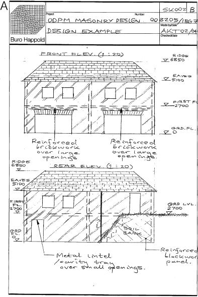
26 Design Guide Handbook for EN 1996 Design of Masonry Structures Again, reference is made to EN it is stated that, if the requirements of EN are followed, it can be assumed that the above requirements are satisfied. Further guidance is given on aspects relating to the loading of masonry after construction. Clearly, BS 5628 Parts 1 and Part 3, in particular provide considerable information on the execution of masonry Design examples Design examples are being provided by one of the project partners - Buro Happold. Their so far limited input at this stage is included in Appendix C. 26
27 EN : Common Rules for Reinforced and Unreinforced Masonry Structures 3. EN : Structural fire design 3.1 Scope Part 1-2 deals with the design of masonry structures for the accidental situation of fire exposure, and is intended to be used in conjunction with EN , EN and EN It only identifies differences from - or supplements to - normal temperature design, and deals only with passive methods of fire protection - active methods are not covered. This Part covers these aspects in a prescriptive, rather than theoretical, way. Specifically, Part 1-2 applies to masonry structures which, for reasons of general fire safety, are required to fulfil certain functions when exposed to fire, in terms of: - avoiding premature collapse of the structure - that is, a load bearing function; and - limiting fire spread (flames, hot gases, excessive heat) beyond designated areas - that is, performing a separating function Part 1-2 gives principles and application rules for designing structures for specified requirements in respect of these functions and levels of performance. It applies to structures, or parts of structures, that are within the scope of EN and EN and are designed accordingly. However, it does not cover reinforced masonry or masonry built with Natural Stone units to EN771-6 Part 1-2 covers the structural fire design of the following walls: - non-load bearing internal walls; - non-load bearing external walls; - load bearing internal walls with separating or non-separating functions; and - load bearing external walls with separating or non-separating functions. Clause 5.8 and Table 15 of BS covers the fire resistance expected of masonry. 3.2 Basic principles and rules Section 2 deals with performance requirements, and the fundamental requirement is that, where mechanical resistance is required, structures must be designed and constructed in such a way that they maintain their load bearing function during the relevant fire exposure. This means that, where compartmentation is required, the elements forming the boundaries of the fire compartment - including the joints - must be designed and constructed in such a way that they maintain their separating function during the relevant fire exposure. This relies on the following being the case: 27
28 Design Guide Handbook for EN 1996 Design of Masonry Structures - no integrity failure occurring - this will prevent the passage of flames and hot gases through the member, and prevent the occurrence of flames on the unexposed side; - no insulation failure occurring - this will limit the temperature rise of the unexposed face to specified levels; - when required, resistance to mechanical impact (M); and - when required, limitation of the thermal radiation from the unexposed side. Where the means of protection - or the design criteria for separating elements - requires consideration of the deformation of the load bearing structure, deformation criteria shall be applied. However, consideration of the deformation of the load bearing structure is not necessary when the separating elements have only a nominal fire exposure. In circumstances where there is a nominal fire exposure - known as the standard fire exposure - the members need to comply with the following criteria: - Mechanical resistance, R - Integrity, E - Insulation, I; and - Mechanical impact, M in the following way: Condition Load bearing only Separating only Separating and load bearing criteria - Load bearing, separating and mechanical impact Separating and mechanical impact Criterion/criteria to be satisfied R E I REI REI-M EI-M The following definitions are given for successfully meeting these criteria: - Criterion R is assumed to be satisfied when the load bearing function is maintained throughout the required time of fire exposure. 28
29 EN : Structural Fire Design - Criterion I is assumed to be satisfied when the mean temperature of the unexposed face does not rise by more 140 K, and the maximum temperature rise at any point of that surface does not exceed 180 K - Criterion E is assumed to be satisfied when the passage of flames and hot gases through the element is prevented. Where a vertical separating element - with or without a load-bearing function - is required to comply with an impact resistance requirement, (Criterion M), the element must resist the application of the horizontal concentrated load specified in EN 1363 Part 2. In circumstances where there is a parametric fire exposure, the load-bearing function is satisfied when collapse is prevented for the complete duration of the fire, including the decay phase, or for a prescribed period of time. Under these circumstances, the separating function, with respect to insulation, is satisfied when the following criteria are met: - the mean temperature rise over the whole of the non-exposed surface does not exceed 140 K and the maximum temperature rise of that surface at any point does not exceed 180 K, at the time of the maximum gas temperature, - the mean temperature rise over the whole of the non-exposed surface does not exceed 180 K, and the maximum temperature rise at any point of that surface does not exceed 220 K during the decay phase of the fire or up to a required period of time. As far as the actions are concerned, Part 1-2 requires the thermal and mechanical actions to be obtained from EN The value of the emissivity of a masonry surface, e m, is contained in a note to clause 2.2(2). As a result, it is a Nationally Determined Parameter, and the value in the UK will be found in the National Annex to Part 1-2, which will follow on from the text in BS EN , when that is published by BSI. Part 1-2 sets out a number of assessment methods by which a fire can be analysed: - testing the structure - tabulated data - member analysis - analysis of part of the structure - global structural analysis Member analysis is assessed following either the requirements set out in EN , with time set to t = 0, or a simplified method given in Clause 2.4.2(2). 29
30 Design Guide Handbook for EN 1996 Design of Masonry Structures As an alternative to carrying out a structural analysis for the fire situation at time t = 0, the reactions at supports and internal forces and moments at boundaries of part of the structure may be obtained from a structural analysis for normal temperature given in clause 5.1.4(2) of EN Finally, in situations where a global structural analysis of the fire is carried out, the relevant failure mode in fire exposure, the temperature-dependent material properties and member stiffness, the effects of thermal expansions and deformations (indirect fire actions) need to be taken into account. 3.3 Materials The requirements for the materials used the masonry construction are given in section 3. For units, the requirements given in EN apply, with the exception of Group 1S. These are defined as Group 1 units containing less than 5% holes. Group 1S units may contain indentations, for example frogs, grip holes or grooves in the bed face, if such indentations will be filled with mortar in the finished wall. The requirements for mortar and masonry at 20 C are those given in EN At elevated temperatures, for heating rates between 2 and 50 K/min, the strength and deformation properties of masonry at elevated temperatures may be obtained from the stress-strain relationship obtained by tests for a project or from a database. Stressstrain relationships for some materials are given in an Annex - Annex D. The unit mass of masonry is considered to be independent of the masonry s temperature, and users of the code are directed to EN to obtain the density of masonry materials. It is expected that the manufacturer will declare values for the density of the masonry units and mortar, in accordance with ENs to 6 and EN Finally, values of the thermal elongation, specific heat capacity and the thermal conductivity are given in clauses (1), (1) and (1), respectively. In all three cases, data in included in Annex D. However, the values for the specific heat capacity and the thermal conductivity are contained in notes and will therefore be Nationally Determined Parameters. As a result, they will appear in the National Annex to BS EN , when that is published by BSI. 3.4 Design procedures for obtaining fire resistance of masonry walls Section 4 covers the design procedures to be followed to provide fire resistant masonry. It should be noted that, for fire protection, a distinction is made between non-load bearing walls and load bearing walls, and between separating walls and non-separating walls. Each of the wall types is then defined: 30
31 EN : Structural Fire Design - Separating walls serve to prevent fire propagation from one place to another, and are exposed to fire on one side only. Examples are walls along escape ways, walls of stair wells, separating walls of a fire compartment. - Non-separating load bearing walls are subjected to fire on two or more sides. Examples are walls within a fire compartment. - External walls may be separating walls, or non-separating walls as required. External separating walls less than 1,0 m in length should be treated as nonseparating walls for the purposes of fire design. Wall areas which include lintels above openings are required to have at least the same fire resistance as the wall itself. Fire walls are separating walls that are additionally required to resist mechanical impact. Examples of their use are to separate buildings or fire compartments. Stiffening elements, such as cross walls, floors, beams, columns or frames, should have at least the same fire resistance as the fire wall. Additional factors to be considered for fire design are: - the use of non-combustible materials - the effect on a fire wall of thermal reaction or expansion of an adjacent construction situated close to the fire wall - the effect on a wall of movement in a fire of columns and beams close to the wall. For cavity walls and untied walls comprising of independent leaves, four wall configurations are assessed and the fire resistance of these four cases are given. The four cases are: 1. When both leaves of a cavity wall are load bearing and carry approximately equal loads: the fire resistance of a cavity wall with leaves of approximately equal thickness is defined as the fire resistance of an equivalent single leaf wall of thickness equal to the sum of the thicknesses of the two leaves. 2. When only one leaf of a cavity wall is load bearing, the resistance of the cavity wall is usually greater than the fire resistance achieved for the load bearing leaf when considered to act as a single leaf wall. 3. The fire resistance of a cavity wall comprising two non-load bearing leaves may be taken as the sum of the fire resistances of the individual leaves, limited to a maximum of 240 min when fire resistance is determined by Part For untied walls comprising independent leaves, the fire resistance of the wall is determined by reference to the appropriate load bearing or non-load bearing table for single leaf walls. 31
32 Design Guide Handbook for EN 1996 Design of Masonry Structures Surface finishes clearly have an impact on the performance of masonry in a fire, and this is acknowledged in clause 4.2 It states that the fire resistance of masonry walls may be increased by the application of a layer of the following mortars, having a thickness of at least 10 mm: - plaster type L-G according to EN gypsum premixed plaster according to EN ; or - plaster type LW or T according to EN For cavity and double leaf walls, render or plaster would be only needed on the outside faces of the leaves, and not between the two leaves. An alternative means of increasing the fire resistance of a wall is to add either an additional masonry leaf or masonry cladding. Further requirements for masonry walls are given in clause 4.3. The points raised are essentially practical items, including the advice that such items as insulation layers made of combustible materials do not enhance fire resistance. Finally, it provides information on assessment by testing, by tabulated data and by calculation. For assessment by testing, the fire resistance can be obtained from tests following the relevant ENs - and clause 1 provides a list of suitable test methods. Guidance on the selection of suitable fire resistance periods is given in Annex A. For assessment using tabulated data, may be carried out using tables given in Annex B. These give the minimum thickness of masonry required, for the relevant criterion, to achieve the stated period of fire resistance, when constructed using units of the material, Group and density given. The point is clearly made that the minimum wall thickness given in the tables relates to the wall s fire resistance only - the thickness required for other considerations as defined in EN , or which is needed to meet other requirements, such as acoustic performance, is not taken into account. The values of γ Glo, used in the tabulated approach, are contained in a note and are therefore a Nationally Determined Parameter. As such, the value of γ Glo to be used in the UK will be found in the National Annex of this Part, which will follow the text in BS EN when it is published by BSI. Finally, the fire resistance of masonry walls may be assessed by calculation, taking into account the relevant failure mode in fire exposure, the temperature dependent material properties, the slenderness ratio and the effects of thermal expansions and deformations. Two calculations method are not included in EN in Annexes C and D. Both these Annexes are informative. 32
33 EN : Structural Fire Design 3.5 Detailing The premise on which the detailing advice set out in section 5 is based is that the detailing of the masonry in a structure should be done with the aim of limiting the spread of fire between the elements of the construction. Detailed guidance is given on junction joints and fixtures, pipes and cables. Again, the advice is of a prescriptive nature. Additional advice on connection between non-load bearing masonry walls is contained in Annex E, which is informative. 33
34 Design Guide Handbook for EN 1996 Design of Masonry Structures 4. EN : Simplified calculation methods and simple rules for masonry structures 4.1 General The aim of EN is to provide simplified calculation methods to facilitate the design of unreinforced masonry walls, subject to certain conditions of application. That is to say, it provides a simplified method of designing walls compared with EN and it is only applicable to the design of walls, not other elements. Specifically, simplified calculation methods are given in Part 3 for : walls subjected to vertical loading, including wind loading; walls subjected to concentrated loads; shear walls; basement walls subjected to lateral earth pressure and vertical loads; walls subjected to vertical loading where the height of the building does not exceed 3 storeys; above ground level; shear walls where the height of the building does not exceed 3 storeys above ground level; and internal walls not subject to vertical loads. Where the type of structure is not covered by the conditions listed above, the design should be based on Part 1-1. The rules given in Part 3 are consistent with those given in Part 1-1, but are more conservative in respect of the conditions and limitations of their use. In addition, Part 3 applies only to those masonry structures, or elements of those structures, that are described in Part 1-1 and Part 2. Finally, the simplified calculation methods given in Part 3 are not applicable to the design for accidental situations. 4.2 Basis of design The basis for designing to Part 3 is fundamentally the same as for Part 1-1, with the design being carried out in accordance with the general rules given in EN The specific provisions for masonry structures followed are those given in section 2 of EN , and again verification is by the partial factor method. A range of values for γ M is given in a table in a note to clause 2.3(3)P. As they are in a note the values are Nationally Determined Parameters and are therefore a matter for national choice. The values to be used will be contained in the National Annex which will follow the text of this Eurocode when the BS EN is published. 34
35 EN : Simplified Calculation Methods and Simple Rules for Masonry Structures 4.3 Materials The section on materials relies heavily on the content of EN : there is the requirement that the material used in the masonry walls in EN must be in accordance with Section 3 of EN However, a simplified method of determining the characteristic compressive strength of masonry is provided in Annex D, which is informative. Instead of following the method set out in Part 1-1, which uses an equation of the form: f k = K f b α f m β, where, f k is the characteristic compressive strength of the masonry K is a constant f b is the normalised mean compressive strength of the masonry unit; and f m is the compressive strength of the mortar, Part 3 uses an equation of the generic form f k = f ko. C1. where, C1 is a constant; and f ko is a compressive strength for the masonry, obtained from a table using the mortar compressive strength and the compressive strength of the masonry unit. The characteristic compressive strength of masonry, f k, can only be determined by the simplified methods when the values of K given in the boxes in ENV are accepted for use without alteration. Separate equations and tables are provided for general purpose mortars, thin layer mortars (with a different equation and tables being used, depending on the unit type) and lightweight mortars. As far as the characteristic flexural strength of the masonry is concerned, a note under clause 3.3(1) gives a table of values for f xk1 and f xk2 dependent on the combination of unit material and the mortar used. The same applies to the characteristic shear strength - a table of suggested values is contained in a note under 3.4(1). In both cases, as these are Nationally Determined Parameters, the precise value to be used in the UK will be contained in the National Annex which will follow the text in BS EN , when it is published. 4.4 Design of unreinforced masonry walls using simplified methods The basis of the design again is defined by EN , as it is a requirement that the overall stability of the building is in accordance with the requirements given in clause 5.1 of EN For the simplified calculation method for walls subjected to vertical loading provided in Part 3 to be used, a number of limiting conditions must be met, including the following: 35
36 Design Guide Handbook for EN 1996 Design of Masonry Structures - the height of the building above ground level does not exceed 20 m; - the span of the floors supported by the walls does not exceed 7 m; - the span of the roof supported by the walls does not exceed 7 m, except in the case of light weight trussed roof construction where the span should not exceed 14 m; - the clear storey height does not exceed 4 m; - the characteristic values of the variable actions on the floors and the roof do not exceed 5,0kN 2 ; - no actions other than those listed are applied; - the walls are to be laterally restrained by the floors and roof in the horizontal direction at right angles to the plane of the wall, either by the floors and roof themselves or by suitable methods e.g. ring beams with sufficient stiffness; - the final creep coefficient of the masonry φ does not exceed 2,0; - the thickness of the wall is the same at all storeys or when the thickness of the wall is not the same at all storeys the wall should be checked at each storey level. - and that the quality of execution does not lead to an accidental eccentricity greater than h ef /450. A further simplified calculation method, applicable to buildings not exceeding 3 storeys in height, is given in Annex A of Part 3 - which is a normative annex. Simplified methods, compared with the versions given in EN , are given for the calculation of: - shear walls, - basement walls; and - internal walls not subjected to vertical loads - i.e. partition walls. 36
37 EN : Simplified Calculation Methods and Simple Rules for Masonry Structures Policy implications There are no policy implications inherent in this report. 37
38 Design Guide Handbook for EN 1996 Design of Masonry Structures Appendix A List of previous reports, with references, for this project BRE output/ milestone reference Title Interim Report on the contents and format of the companion document and handbook - EN1996 Report containing first draft Design Guide Handbook for EN 1996 Design of Masonry Structures. Date submitted 15 December March
39 Appendices Appendix B Project summary The overall aim of this project is to encourage a satisfactory level of adoption of EN1996: Design of Masonry Structures within the construction industry during the period that it is coexistent with the UK national codes, particularly BS5628 Use of Masonry. The project will concentrate on EN (Rules for Reinforced and Unreinforced Masonry) and selected parts of EN (Structural Fire Design). The specific objectives of the project are: Identification of major differences in the detailed design methods and production of a handbook for practitioners in order to guide them through the design process. As an aid to the design and specification process, provision of a companion document describing the scope and coverage of the Eurocode and its application document to support EN1996. Presentation of both documents in an agreed form ready for publication. 39
40 Design Guide Handbook for EN 1996 Design of Masonry Structures Appendix C Buro Happold notes on design approach for the design examples 40
41 Appendices 41
42 Design Guide Handbook for EN 1996 Design of Masonry Structures 42
43 Appendices 43

44 Design Guide Handbook for EN 1996 Design of Masonry Structures 44
45 Appendices 45

46 Design Guide Handbook for EN 1996 Design of Masonry Structures 46
Eurocode 6 Design of masonry structures
 BRITISH STANDARD Eurocode 6 Design of masonry structures BS EN 1996-1-1:2005 Incorporating corrigenda February 2006 and July 2009 Part 1-1: General rules for reinforced and unreinforced masonry structures
pren : Redraft 9A
 Page 1 pren 1996-1-1: Redraft 9A Eurocode 6: Design of Masonry Structures Part 1-1: Common rules for reinforced and unreinforced masonry structures Sent out: September 2001 (Revised: October 2001) Page
mortarless masonry Design Manual Part 1 (BS 5628:2005) Section 1 Page 1 BS 5628:2005 CODE OF PRACTICE FOR THE USE OF MASONRY
 Section 1 Page 1 BS 5628:2005 CODE OF PRACTICE FOR THE USE OF MASONRY") SECTION 1. mortarless masonry Design Manual Part 1 (BS 5628:2005) Section 1 Page 1 1.1 Overview of BS 5628:2005 BS 5628:2005 CODE OF PRACTICE FOR THE USE OF MASONRY BS 5628:2005 Code of practice for the
SECTION 1. mortarless masonry Design Manual Part 1 (BS 5628:2005) Section 1 Page 1 1.1 Overview of BS 5628:2005 BS 5628:2005 CODE OF PRACTICE FOR THE USE OF MASONRY BS 5628:2005 Code of practice for the
DS/EN DK NA:2013
 National Annex to Eurocode 6: Design of masonry structures - Part 1-1: General rules for reinforced and unreinforced masonry structures Foreword This national annex (NA) is a revision and compilation of
mortarless masonry Design Manual Part 1 (IS 456:2000) Section 1 Page 1 IS 456:2000 PLAIN AND REINFORCED CONCRETE - CODE OF PRACTICE
 Section 1 Page 1 IS 456:2000 PLAIN AND REINFORCED CONCRETE - CODE OF PRACTICE") SECTION 1. mortarless masonry Design Manual Part 1 (IS 456:2000) Section 1 Page 1 1.1 Overview of IS 456:2000 IS 456:2000 PLAIN AND REINFORCED CONCRETE - CODE OF PRACTICE IS 456:2000 is the current Indian
SECTION 1. mortarless masonry Design Manual Part 1 (IS 456:2000) Section 1 Page 1 1.1 Overview of IS 456:2000 IS 456:2000 PLAIN AND REINFORCED CONCRETE - CODE OF PRACTICE IS 456:2000 is the current Indian
BS EN :2004 EN :2004 (E)
") Contents List 1. General 1.1 Scope 1.1.1 Scope of Eurocode 2 1.1.2 Scope of Part 1-1 of Eurocode 2 1.2 Normative references 1.2.1 General reference standards 1.2.2 Other reference standards 1.3 Assumptions
Contents List 1. General 1.1 Scope 1.1.1 Scope of Eurocode 2 1.1.2 Scope of Part 1-1 of Eurocode 2 1.2 Normative references 1.2.1 General reference standards 1.2.2 Other reference standards 1.3 Assumptions
SOUTH AFRICAN NATIONAL STANDARD
 ISBN 978-0-626-20611-6 SOUTH AFRICAN NATIONAL STANDARD The structural use of masonry Part 2: Structural design and requirements for reinforced and prestressed masonry WARNING To be used in conjunction
EUROCODE 6 Design of masonry structures
 Dissemination of information for training Brussels, 2-3 April 2009 1 EUROCODE 6 Design of masonry structures Dissemination of information for training Brussels, 2-3 April 2009 2 Laterally Loaded Masonry
CD 360 Use of Compressive Membrane Action in Bridge Decks
 Design Manual for Roads and Bridges Highway Structures & Bridges Design CD 360 Use of Compressive Membrane Action in Bridge Decks (formerly BD 81/02) Revision 1 Summary This document provides requirements
EN REINFORCED MASONRY DESIGN EXAMPLE 1 (NOTE: THIS USES THE UK NATIONAL ANNEX NDP VALUES)
") 42.50 10.00 3.00 20.00 EN 1996-1-1 REINFORCED MASONRY DESIGN EXAMPLE 1 (NOTE: THIS USES THE UK NATIONAL ANNEX NDP VALUES) Reinforced Masonry - Reinforced Brickwork Stem Cantilever Pocket-Type Retaining
42.50 10.00 3.00 20.00 EN 1996-1-1 REINFORCED MASONRY DESIGN EXAMPLE 1 (NOTE: THIS USES THE UK NATIONAL ANNEX NDP VALUES) Reinforced Masonry - Reinforced Brickwork Stem Cantilever Pocket-Type Retaining
Chapter. Masonry Design
 Chapter Masonry Design The masonry design section contains modules for the analysis of reinforced masonry beams subjected to pure bending and unreinforced masonry walls subjected to axial compression and
Client Report : A design method for use with 6mm diameter Thor Helical twistfix wires used as retrofitted bedjoint reinforcement
 Client Report : A design method for use with 6mm diameter Thor Helical twistfix wires used as retrofitted bedjoint reinforcement Client report number 214151 Prepared for : Dave Chadwick 19 th November
Eurocode 8 Timber and Masonry structures
 Brussels, 18-20 February 2008 Dissemination of information workshop 1 Eurocode 8 Timber and Masonry structures E C Carvalho, Chairman TC250/SC8 Brussels, 18-20 February 2008 Dissemination of information
Concrete Design Guide
 Number 7 38 TheStructuralEngineer Technical July 2015 Post-tensioned slabs Concrete Design Guide No. 7: Design of post-tensioned slabs This series is produced by The Concrete Centre to enable designers
Ce 479 Reinforced Masonry Fall 2005
 INTRODUCTION TO STRUCTURAL DESIGN OF REINFORCED MASONRY In the preceding lecture on structural design of masonry, we have seen examples of unreinforced masonry bearing walls. In bearing walls, when the
Eurocode 6 Design of masonry structures
 BRITISH STANDARD BS EN 1996-3:2006 Incorporating corrigendum October 2009 Eurocode 6 Design of masonry structures Part 3: Simplified calculation methods for unreinforced masonry structures ICS 91.010.30;
SECTION 1. AS MASONRY STRUCTURES CODE
 mortarless masonry Design Manual Part 1 (AS 3700:2011) Section 1 Page: 1 SECTION 1. AS 3700 - MASONRY STRUCTURES CODE AS 3700:2011 Masonry structures is the current Australian standard for the design of
Contents. 1.1 Introduction 1
 Contents PREFACE 1 ANCIENT MASONRY 1 1.1 Introduction 1 1.2 History of Masonry Materials 1 1.2.1 Stone 2 1.2.2 Clay Units 2 1.2.3 Calcium Silicate Units 4 1.2.4 Concrete Masonry Units 4 1.2.5 Mortars 5
Design of Composite Bridges Use of BS 5400: Part 5: 1979
 THE HIGHWAYS AGENCY THE SCOTTISH OFFICE DEVELOPMENT DEPARTMENT Amendment No.1, dated 10 December 1987 THE WELSH OFFICE Y SWYDDFA GYMREIG THE DEPARTMENT OF THE ENVIRONMENT FOR NORTHERN IRELAND Design of
BOUNDARY CONDITIONS OF SHEAR WALLS IN MULTI-STOREY MASONRY STRUCTURES UNDER HORIZONTAL LOADINGS
 BOUNDARY CONDITIONS OF SHEAR WALLS IN MULTI-STOREY MASONRY STRUCTURES UNDER HORIZONTAL LOADINGS K. ZILCH Professor, Institute of Building Materials and Structures Chair of Concrete Structures Technische
Recommendations for additional fire protection of structural elements
 ANNEX 6 Recommendations for additional fire protection of structural elements 1 Scope This Annex contains a series of recommendations applicable to structural concrete structures which, for general fire
Contents. Foreword 1 Introduction 1
 Contents Notation x Foreword xiii 1 Introduction 1 1.1 Aims of the Manual 1 1.2 Eurocode system 1 1.3 Scope of the Manual 3 1.4 Contents of the Manual 4 1.5 Notation and terminology 4 2 General principles
mortarless Design Manual Part 3 (AS 3600:2009) Section 2 Page: DESIGN OF WALLS FOR AXIAL COMPRESSION USING SIMPLIFIED DESIGN METHOD
 Section 2 Page: DESIGN OF WALLS FOR AXIAL COMPRESSION USING SIMPLIFIED DESIGN METHOD") 1 SECTION 2. DESIGN OF WALLS FOR AXIAL COMPRESSION USING SIMPLIFIED DESIGN METHOD Many walls are designed using the simplified design method of AS 3600 Clause 11.5 and this Section 2 of the design manual
1 SECTION 2. DESIGN OF WALLS FOR AXIAL COMPRESSION USING SIMPLIFIED DESIGN METHOD Many walls are designed using the simplified design method of AS 3600 Clause 11.5 and this Section 2 of the design manual
mortarless Design Manual Part 1 (AS 3600:2009) Section 1 Page 1 AS 3600:2009 PLAIN AND REINFORCED CONCRETE - CODE OF PRACTICE
 Section 1 Page 1 AS 3600:2009 PLAIN AND REINFORCED CONCRETE - CODE OF PRACTICE") SECTION 1. mortarless Design Manual Part 1 (AS 3600:2009) Section 1 Page 1 AS 3600:2009 PLAIN AND REINFORCED CONCRETE - CODE OF PRACTICE 1.1 Overview of AS 3600:2009 AS 3600:2009 is the latest Australian
SECTION 1. mortarless Design Manual Part 1 (AS 3600:2009) Section 1 Page 1 AS 3600:2009 PLAIN AND REINFORCED CONCRETE - CODE OF PRACTICE 1.1 Overview of AS 3600:2009 AS 3600:2009 is the latest Australian
Masonry and Cold-Formed Steel Requirements
 PC UFC Briefing September 21-22, 2004 Masonry and Cold-Formed Steel Requirements David Stevens, ARA Masonry Requirements Composite Construction Masonry is often used in composite construction, such as
Eurocodes European Codes for Structural Design. H. J. Bossenmayer, Prof. Dr.-Ing., is president, Deutsches Institut für Bautechnik, Berlin, Germany
 Eurocodes European Codes for Structural Design H. J. Bossenmayer, Prof. Dr.-Ing., is president, Deutsches Institut für Bautechnik, Berlin, Germany ABSTRACT The structural Eurocodes are an unrivalled set
Structural Eurocodes an overview
 Structural Eurocodes an overview BS EN 1990, Eurocode Basis of Structural Design Structural safety, serviceability and durability BS EN 1991, Eurocode 1 Actions on Structures Actions on structures BS EN
Technical Notes 24G - The Contemporary Bearing Wall - Detailing [Dec. 1968] (Reissued Feb. 1987) INTRODUCTION
![Technical Notes 24G - The Contemporary Bearing Wall - Detailing [Dec. 1968] (Reissued Feb. 1987) INTRODUCTION](/thumbs/77/75098995.jpg "Technical Notes 24G - The Contemporary Bearing Wall - Detailing [Dec. 1968] (Reissued Feb. 1987) INTRODUCTION") Technical Notes 24G - The Contemporary Bearing Wall - Detailing [Dec. 1968] (Reissued Feb. 1987) INTRODUCTION The selection of a wall type and appropriate connection details is one of the most important
Technical Notes 24G - The Contemporary Bearing Wall - Detailing [Dec. 1968] (Reissued Feb. 1987) INTRODUCTION The selection of a wall type and appropriate connection details is one of the most important
PRINCIPLES OF CONCRETE DESIGN
 29 PRINCIPLES OF CONCRETE DESIGN Actions on structures and Limit state method Beams Columns Slabs Frames Special Structures MITOITUSPERUSTEET- osio Kuormitukset ja osavarmuuskerroinmenettely Palkit Pilarit
MASONRY WALL PANEL DESIGN (EN :2005)
") App'd by MASONRY WALL PANEL DESIGN (EN199611:2005) In February 2006 and July 2009 and the recommended values Masonry panel details Singleleaf wall example Unreinforced masonry wall without openings Panel
App'd by MASONRY WALL PANEL DESIGN (EN199611:2005) In February 2006 and July 2009 and the recommended values Masonry panel details Singleleaf wall example Unreinforced masonry wall without openings Panel
ISSUE A Code Change # 2 Class 3 and Class 4 Buildings
 ISSUE A Code Change # 2 Class 3 and Class 4 Buildings (new) Section 1604.9 Disproportionate Collapse. Design for structural integrity of new buildings to protect against disproportionate collapse shall
DESIGN OF LARGE SIZE NON-LOADBEARING MASONRY WALLS: CASE STUDIES IN PORTUGAL. TECHNICAL AND ECONOMICAL BENEFITS
 3 th International Brick and Block Masonry Conference Amsterdam, July 4-7, 004 DESIGN OF LARGE SIZE NON-LOADBEARING MASONRY WALLS: CASE STUDIES IN PORTUGAL. TECHNICAL AND ECONOMICAL BENEFITS Paulo B. Lourenço
EN 1996 DESIGN OF MASONRY STRUCTURES
 -- REINFORCED AND PRESTRESSED MASONRY -- Dissemination of information for training Brussels, 2-3 April 2009 1 EN 1996 DESIGN OF MASONRY STRUCTURES - REINFORCED AND PRESTRESSED MASONRY - 2 and 3 April 2009
Experimental investigations on the influence of thermal elements on the structural stability of modern masonry walls
 Brick and Block Masonry Trends, Innovations and Challenges Modena, da Porto & Valluzzi (Eds) 2016 Taylor & Francis Group, London, ISBN 978-1-138-02999-6 Experimental investigations on the influence of
DIN EN : (E)
") DIN EN 1999-1-1:2014-03 (E) Eurocode 9: Design of aluminium structures - Part 1-1: General structural rules Contents Page Foreword to EN 1999-1-1:2007... 7!Foreword to EN 1999-1-1:2007/A1:2009... 7 #Foreword
DIN EN 1999-1-1:2014-03 (E) Eurocode 9: Design of aluminium structures - Part 1-1: General structural rules Contents Page Foreword to EN 1999-1-1:2007... 7!Foreword to EN 1999-1-1:2007/A1:2009... 7 #Foreword
Technical Guidance Note
 Technical Guidance Note THE BUILDING REGULATIONS 2004 EDITION ENGLAND AND WALES REQUIREMENT A3 DISPROPORTIONATE COLLAPSE 1. INTRODUCTION (a) This technical guidance note outlines NHBC s interpretation
Lecture Retaining Wall Week 12
 Lecture Retaining Wall Week 12 Retaining walls which provide lateral support to earth fill embankment or any other form of material which they retain them in vertical position. These walls are also usually
COLUMNS 1- Definition: The Egyptian code defines columns as : 2- Types of concrete columns
 COLUMNS 1- Definition: Columns are vertical compression members which carry primarily axial compression load; the axial load may be associated with bending moments in one or two directions, as shown in
Characteristic strengths of masonry
 Page 1 of 5 Determination of characteristic compressive strength of masonry, f k Currently in the UK, masonry design may be carried out in accordance with Eurocode 6 (EC6) EN1996-1-1 or the withdrawn British
Serviceability considerations
 Serviceability considerations Presented by: Jan Wium / John Robberts Stellenbosch University NUCSE Table of contents Stress limitation (Chapter 7) Crack control (Chapter 7) Deflection control (Chapter
Copyright 2016 UL LLC.
 File number: NC26871 Project number: 47867376460 23rd March 2016 ASSESSMENT REPORT concerning The Ability of Masonry Walls Consisting of Hollow Concrete Blocks Known as Wi Slot Blocks in Conjunction with
CLT Structural Design Sylvain Gagnon, Eng. February 8, 2011 Vancouver
 www.fpinnovations.ca CLT Structural Design Sylvain Gagnon, Eng. February 8, 2011 Vancouver Structural Design Handbook 10/02/2011 2 Critical Characteristics for CLT used as floor/roof Short-term and long-term
Contents. Tables. Notation xii Latin upper case letters Latin lower case letters Greek upper case letters Greek lower case letters. Foreword.
 Tables x Notation xii Latin upper case letters Latin lower case letters Greek upper case letters Greek lower case letters xii xiv xvi xvi Foreword xviii 1 Introduction 1 1.1 Aims of the Manual 1 1.2 Eurocode
Flexure and Serviceability Limit State
 UNIT 3 Flexure and Serviceability Limit State Beam A structural member that support transverse (Perpendicular to the axis of the member) load is called a beam. Beams are subjected to bending moment and
Technical Guidance Document TGD-021-6
 DEPARTMENT OF EDUCATION AND SKILLS Planning & Building Unit Technical Guidance Document TGD-021-6 Structural Guidelines Disproportionate Collapse, Horizontal Tie, Vertical Tie and the Requirements in the
A Guide for the Interpretation of Structural Design Options for Residential Concrete Structures
 CFA Technical Note: 008-2010 A Guide for the Interpretation of Structural Design Options for Residential Concrete Structures CFA Technical This CFA Technical Note is intended to serve as a guide to assist
Seminar Bridge Design with Eurocodes
 Seminar Bridge Design with Eurocodes JRC Ispra, 1-2 October 2012 1 EU-Russia Regulatory Dialogue: Construction Sector Subgroup Seminar Bridge Design with Eurocodes JRC-Ispra, 1-2 October 2012 Organized
CHAPTER 11: PRESTRESSED CONCRETE
 CHAPTER 11: PRESTRESSED CONCRETE 11.1 GENERAL (1) This chapter gives general guidelines required for the design of prestressed concrete structures or members with CFRM tendons or CFRM tendons in conjunction
WATER RESEARCH COMMISSION. KSA 1: Water Resource Management. Thrust 2: Management of Natural and Human-induced Impacts on Water Resources
 WATER RESEARCH COMMISSION KSA 1: Water Resource Management Thrust 2: Management of Natural and Human-induced Impacts on Water Resources P3: Integrated flood and drought management REPORT ON DESIGN CODES
CADS A3D MAX. How to model shear walls
 CADS A3D MAX How to model shear walls Modelling shear walls in A3D MAX Introduction and synopsis This paper explains how to model shear walls in A3D MAX using the `wide column rigid arm sub-frame described
REINFORCED CONCRETE DESIGN
 REINFORCED CONCRETE DESIGN Other Macmillan titles of related interest Microcomputer Applications in Structural Engineering W. H. Mosley and W. J. Spencer Reinforced Concrete Design by Computer R. Hulse
Introduction to Structural Analysis TYPES OF STRUCTURES LOADS AND
 AND Introduction to Structural Analysis TYPES OF STRUCTURES LOADS INTRODUCTION What is the role of structural analysis in structural engineering projects? Structural engineering is the science and art
2012 IBC/2011 MSJC MASONRY CODE COMPILATION
 2012 IBC/2011 MSJC MASONRY CODE COMPILATION 2012 IBC CHAPTER 21 MASONRY Merged IBC/MSJC 2011 MSJC CODE CHAPTER 1 BUILDING CODE REQUIREMENTS AND SPECIFICATION FOR MASONRY STRUCTURES SECTION 2101 GENERAL
EN 1996: Design of masonry structures General rules - Structural fire design
 EUROPEAN STANDARD EN 1996-1-2 NORME EUROPÈENNE 1 st Draft EUROPÄISCHE NORM November 0 EN 1996: Design of masonry structures part 1-2: General rules - Structural fire design Eurocode 6: Calcul es ouvrages
Technical Notes 39A - Testing for Engineered Brick Masonry - Determination of Allowable Design Stresses [July/Aug. 1981] (Reissued December 1987)
![Technical Notes 39A - Testing for Engineered Brick Masonry - Determination of Allowable Design Stresses [July/Aug. 1981] (Reissued December 1987)](/thumbs/75/72632512.jpg "Technical Notes 39A - Testing for Engineered Brick Masonry - Determination of Allowable Design Stresses [July/Aug. 1981] (Reissued December 1987)") Technical Notes 39A - Testing for Engineered Brick Masonry - Determination of Allowable Design Stresses [July/Aug. 1981] (Reissued December 1987) INTRODUCTION Prior to the development of a rational design
Technical Notes 39A - Testing for Engineered Brick Masonry - Determination of Allowable Design Stresses [July/Aug. 1981] (Reissued December 1987) INTRODUCTION Prior to the development of a rational design
Shear resistance of masonry walls and Eurocode 6: shear versus tensile strength of masonry
 DOI 10.1617/s11527-008-9430-6 ORIGINAL ARTICLE Shear resistance of masonry walls and Eurocode 6: shear versus tensile strength of masonry Miha Tomaževič Received: 7 April 2008 / Accepted: 17 September
Appendix M 2010 AASHTO Bridge Committee Agenda Item
 Appendix M 2010 AASHTO Bridge Committee Agenda Item 2010 AASHTO BRIDGE COMMITTEE AGENDA ITEM: SUBJECT: LRFD Bridge Design Specifications: Section 5, High-Strength Steel Reinforcement TECHNICAL COMMITTEE:
HISTORICAL REVIEW OF MASONRY STANDARDS IN NEW ZEALAND
 New Zealand Masonry Standards Page 1 HISTORICAL REVIEW OF MASONRY STANDARDS IN NEW ZEALAND Prepared by Peter C Smith and Jonathan W Devine of Spencer Holmes Ltd for the ROYAL COMMISSION OF INQUIRY BUILDING
VARIOUS TYPES OF SLABS
 VARIOUS TYPES OF SLABS 1 CHOICE OF TYPE OF SLAB FLOOR The choice of type of slab for a particular floor depends on many factors. Economy of construction is obviously an important consideration, but this
Chapter 2 Notation and Terminology
 Reorganized 318 Chapter Titles Chapter 1 General 1.1 Scope 1.2 Purpose 1.3 Interpretation 1.4 Drawings and Specifications 1.5 Testing and Inspection 1.6 Administatration and Enforcement 1.6.1 Retention
Pronto Block Walls. Structural Design Manual AS 3600:2009. masonry. style and function
 Pronto Block Walls Structural Design Manual AS 3600:2009 masonry. style and function pronto block walls design manual Part 1 AS 3600:2009 Warwick Colefax BE(Hons) DipTechEng(Struct) MIEAust CPEng RPEQ
CHAPTER 2. Design Formulae for Bending
 CHAPTER 2 Design Formulae for Bending Learning Objectives Appreciate the stress-strain properties of concrete and steel for R.C. design Appreciate the derivation of the design formulae for bending Apply
Unit 48: Structural Behaviour and Detailing for Construction. Limit State Design
 2.1 Introduction Limit State Design Limit state design of an engineering structure must ensure that (1) under the worst loadings the structure is safe, and (2) during normal working conditions the deformation
7. SPECIFIC RULES FOR STEEL CONCRETE COMPOSITE BUILDINGS
 Page 130 7. SPECIFIC RULES FOR STEEL CONCRETE COMPOSITE BUILDINGS 7.1 General 7.1.1 Scope (1) P For the design of composite steel concrete buildings, Eurocode 4 applies. The following rules are additional
The Edge Protection Federation Containment Systems Product Specification, Test Methods
 The Edge Protection Federation Containment Systems Product Specification, Test Methods Revision 2 August 2016 This Standard defines how the Edge Protection Federation defines Containment. This document
August 2016 DESIGNING FOR MOVEMENT IN BRICKWORK
 August 2016 DESIGNING FOR MOVEMENT IN BRICKWORK 2 Contents Page INTRODUCTION 3 VERTICAL MOVEMENT 4-5 JOINTS SPACING MOVEMENT JOINT POSITIONS 6-10 AND BUILDING DETAILS HORIZONTAL JOINTS TO ACCOMODATE 11
Advanced Eurocode Training. EN : Composite Structures
 Advanced Eurocode Training EN 1994-1-1: Composite Structures Eurocode Training EN 1994-1-1 All information in this document is subject to modification without prior notice. No part of this manual may be
BEHAVIOR OF INFILL MASONRY WALLS STRENGTHENED WITH FRP MATERIALS
 BEHAVIOR OF INFILL MASONRY WALLS STRENGTHENED WITH FRP MATERIALS D.S. Lunn 1,2, V. Hariharan 1, G. Lucier 1, S.H. Rizkalla 1, and Z. Smith 3 1 North Carolina State University, Constructed Facilities Laboratory,
Preface to the Third Edition
 SMDA01 20/03/2006 10:28 AM Page x Preface to the Third Edition The original Structural Masonry Designers Manual was viewed by many in the industry as a seminal reference for structural engineers designing
NATIONAL ANNEX TO STANDARD. SFS-EN EUROCODE 1: ACTIONS ON STRUCTURES Part 1-7: General actions Accidental actions
 ANNEX 37 NATIONAL ANNEX TO STANDARD SFS-EN 1991-1-7 EUROCODE 1: ACTIONS ON STRUCTURES Part 1-7: General actions Accidental actions Preface This National Annex is used together with the Standard SFS-EN
MODELLING OF SHEAR FAILURE MECHANISM OF MASONRY WALLS
 11 th Canadian Masonry Symposium, Toronto, Ontario, May 31- June 3, 2009 MODELLING OF SHEAR FAILURE MECHANISM OF MASONRY WALLS M. Tomaževič 1, M. Gams 1 and S. Lu 2 1 Slovenian National Building and Civil
CHAPTER 5 FINITE ELEMENT MODELING
 CHAPTER 5 FINITE ELEMENT MODELING 5.1 INTRODUCTION Masonry is a composite material with the building brick units and the mortar as the joining material, which are bonded together. Guinea [2000] 51 reported
APPENDIX B ABC STRUCTURES DESIGN GUIDE
 APPENDIX B ABC STRUCTURES DESIGN GUIDE The Cohos Evamy Partners TABLE OF CONTENTS Page No. DISCLAIMER... I 1. STRUCTURAL DESIGN GUIDELINES... 1 2. GENERAL REQUIREMENTS (FIGURE B.2, STEP 1)... 1 3. GENERAL
Masonry (Systematic Rehabilitation)
") 7. Masonry 7.1 Scope This chapter describes engineering procedures for estimating seismic performance of vertical lateralforce-resisting masonry elements. The methods are applicable for masonry wall and
7. Masonry 7.1 Scope This chapter describes engineering procedures for estimating seismic performance of vertical lateralforce-resisting masonry elements. The methods are applicable for masonry wall and
Schöck Isokorb type CV
 Schöck Isokorb type The Schöck Isokorb type is suitable for supported reinforced concrete slabs. (C concrete slab) It transmits positive shear force (vertical shear). 71 72 Section/element arrangement
Guide to the use of EN Accidental Actions
 Guide to the use of EN 1991-1-7 Accidental Actions September 2006 Department for Communities and Local Government: London On 5th May 2006 the responsibilities of the Office of the Deputy Prime Minister
SECTION 10. DESIGN FOR SHEAR
 mortarless masonry Design Manual Part 1 (AS 3700:2011) Section 10 Page: 1 SECTION 10. DESIGN FOR SHEAR Mortarless masonry members can be designed as unreinforced masonry or reinforced masonry. Even if
UNIT-1 RETAINING WALLS
 UNIT-1 RETAINING WALLS PART-A 1. Describe about Retaining wall. 2. Define gravity retaining walls. BT-1 3. Classify the types of retaining walls. 4. Explain cantilever retaining wall? 5. Describe about
10-COLUMNS: 10.1 Introduction.
 1 10-COLUMNS: 10.1 Introduction. Columns are vertical compression members of a structural frame intended to support the loadcarrying beams. They transmit loads from the upper floors to the lower levels
3.4.2 DESIGN CONSIDERATIONS
 3.4.2 DESIGN CONSIDERATIONS Formwork Where Flatdeck sheet is used as formwork, the profile provides resistance to wet concrete (G) and construction loads (Q). Maximum formwork spans given in Section 3.4.4.1
(a) Pin-Pin P cr = (b) Fixed-Fixed P cr = (d) Fixed-Pin P cr =
 Pin-Pin P cr = (b) Fixed-Fixed P cr = (d) Fixed-Pin P cr =") 1. The most critical consideration in the design of rolled steel columns carrying axial loads is the (a) Percent elongation at yield and the net cross-sectional area (b) Critical bending strength and axial
1. The most critical consideration in the design of rolled steel columns carrying axial loads is the (a) Percent elongation at yield and the net cross-sectional area (b) Critical bending strength and axial
Draft for Public Comment Australian Standard
 COMMITTEE BD-004 DR AS 3700:2017 (Project ID: 104048) Draft for Public Comment Australian Standard LIABLE TO ALTERATION DO NOT USE AS A STANDARD BEGINNING DATE FOR COMMENT: CLOSING DATE FOR COMMENT: 26
THE BEHAVIOUR OF LIGHTWEIGHT COMPOSITE FLOOR TRUSSES IN FIRE
 THE BEHAVIOUR OF LIGHTWEIGHT COMPOSITE FLOOR TRUSSES IN FIRE S.K. Choi, I.W. Burgess Department of Civil and Structural Engineering, University of Sheffield, Sheffield S1 3JD, UK R.J. Plank School of Architecture,
Eurocode 9: Design of aluminium structures
 BRITISH STANDARD BS EN 1999-1-1:2007 +A1:2009 Eurocode 9: Design of aluminium structures Part 1-1: General structural rules ICS 77.150.10; 91.010.30; 91.080.10 National foreword This British Standard was
1. BS 5950: Structural use of steelwork in building Part 1: Code of practice for design of simple and continuous construction, BSI, 1990
 Bibliography 1. BS 5950: Structural use of steelwork in building Part 1: Code of practice for design of simple and continuous construction, BSI, 1990 2. BS 6399: Loading for buildings Part 1: Code of practice
Seismic Behaviour of RC Shear Walls
 Ductile Detailing of RC Structures :: IS:13920-1993 1993 Short Course on Seismic Design of RC Structures Durgesh C. Rai Department of Civil Engineering, IIT Kanpur The material contained in this lecture
Table 3. Detailed Comparison of Structural Provisions of IRC 2000 and 1997 NEHRP (Continued)
") 2000 IRC 1997 NEHRP Section Provision Section Provision Comments CHAPTER 3 BUILDING PLANNING R301 DESIGN CRITERIA R301.2.2 Seismic Provisions R301.2.2.1 Determination of Seismic Design Category R301.2.2.1.1
2000 IRC 1997 NEHRP Section Provision Section Provision Comments CHAPTER 3 BUILDING PLANNING R301 DESIGN CRITERIA R301.2.2 Seismic Provisions R301.2.2.1 Determination of Seismic Design Category R301.2.2.1.1
BEHAVIOUR OF REINFORCED CONCRETE STRUCTURES IN FIRE
 BEHAVIOUR OF REINFORCED CONCRETE STRUCTURES IN FIRE ZHAOHUI HUANG, IAN W. BURGESS and ROGER J. PLANK 3 ABSTRACT In the past two decades, a significant amount of research has been conducted into the performance
VOLUNTARY - EARTHQUAKE HAZARD REDUCTION IN EXISTING HILLSIDE BUILDINGS (Division 94 Added by Ord. No. 171,258, Eff. 8/30/96.)
") DIVISION 94 VOLUNTARY - EARTHQUAKE HAZARD REDUCTION IN EXISTING HILLSIDE BUILDINGS (Division 94 Added by Ord. No. 171,258, Eff. 8/30/96.) SEC. 91.9401. PURPOSE. (Amended by Ord. No. 172,592, Eff. 6/28/99,
DIVISION 94 VOLUNTARY - EARTHQUAKE HAZARD REDUCTION IN EXISTING HILLSIDE BUILDINGS (Division 94 Added by Ord. No. 171,258, Eff. 8/30/96.) SEC. 91.9401. PURPOSE. (Amended by Ord. No. 172,592, Eff. 6/28/99,
Building Design Data
 Building Design Data.. 1. Building Design The KORE ICF System is designed to meet the requirements of the Building Regulations 1997-2006, in the case of two storeys, single occupancy dwellings. If the
Licensed Copy: Sheffield University, University of Sheffield, 23 October 2002, Uncontrolled Copy, (c) BSI
 BSI") BRITISH STANDARD Structural use of concrete Licensed Copy: Sheffield University, University of Sheffield, 23 October 2002, Uncontrolled Copy, (c) BSI Part 3: Design charts for singly reinforced beams,
BRITISH STANDARD Structural use of concrete Licensed Copy: Sheffield University, University of Sheffield, 23 October 2002, Uncontrolled Copy, (c) BSI Part 3: Design charts for singly reinforced beams,
Eurocode 8: Design of structures for earthquake resistance
 BRITISH STANDARD BS EN 1998-1:2004 Incorporating corrigendum July 2009 and January 2011 Eurocode 8: Design of structures for earthquake resistance Part 1: General rules, seismic actions and rules for buildings
CHAPTER 10: GENERAL STRUCTURAL DETAILS
 CHAPTER 10: GENERAL STRUCTURAL DETAILS 10.1 GENERAL It shall be in accordance with JSCE Standard Specification (Design), 9.1, "steel" shall be taken to signify "steel or CFRM". 10.2 CONCRETE COVER (1)
PRESTRESSED CONCRETE STRUCTURES. Amlan K. Sengupta, PhD PE Department of Civil Engineering Indian Institute of Technology Madras
 PRESTRESSED CONCRETE STRUCTURES Amlan K. Sengupta, PhD PE Department of Civil Engineering Indian Institute of Technology Madras Module 5: Analysis and Design for Shear and Torsion Lecture-23: Analysis
Technical Memorandum (Bridges) Rules for the Design and Use of Freyssinet Concrete Hinges in Highway Structures
 Rules for the Design and Use of Freyssinet Concrete Hinges in Highway Structures") THE HIGHWAYS AGENCY THE SCOTTISH OFFICE DEVELOPMENT DEPARTMENT THE WELSH OFFICE Y SWYDDFA GYMREIG THE DEPARTMENT OF THE ENVIRONMENT FOR NORTHERN IRELAND Technical Memorandum (Bridges) Rules for the Design
THE HIGHWAYS AGENCY THE SCOTTISH OFFICE DEVELOPMENT DEPARTMENT THE WELSH OFFICE Y SWYDDFA GYMREIG THE DEPARTMENT OF THE ENVIRONMENT FOR NORTHERN IRELAND Technical Memorandum (Bridges) Rules for the Design
Tekla Structural Designer 2016
 Tekla Structural Designer 2016 Reference Guides (AS Non-Composite Steel) April 2016 2016 Trimble Solutions Corporation part of Trimble Navigation Ltd. Table of Contents Loading - Australian Standards...
Eurocode Training EN : Composite Structures
 Eurocode Training EN 1994-1-1: Composite Structures All information in this document is subject to modification without prior notice. No part of this manual may be reproduced, stored in a database or retrieval
Experimental study on the seismic performance of RC moment resisting frames with precast-prestressed floor units.
 Experimental study on the seismic performance of RC moment resisting frames with precast-prestressed floor units. B.H.H. Peng, R.C. Fenwick, R.P. Dhakal & D.K. Bull Department of Civil and Natural Resources
Strength Design of Reinforced Concrete Structures
 Chapter 6 Strength Design of Reinforced Concrete Structures 6.1 Analysis and Design General Considerations 6.1.1 Convention and Notation Unless otherwise explicitly stated, the following units shall be
BISON PRECAST FLOORING SPECIFICATION
 BISON PRECAST FLOORING SPECIFICATION 1.0 SCOPE OF THE SPECIFICATION 1.01 Relates to: This specification covers the design, manufacture and associated site work of the following types of floors:- Hollowcore