Wall Panels. Structural wall panel. Architectural wall panel. Cladding wall panel. Sandwich wall panel
|
|
|
- Gerald Glenn
- 6 years ago
- Views:
Transcription

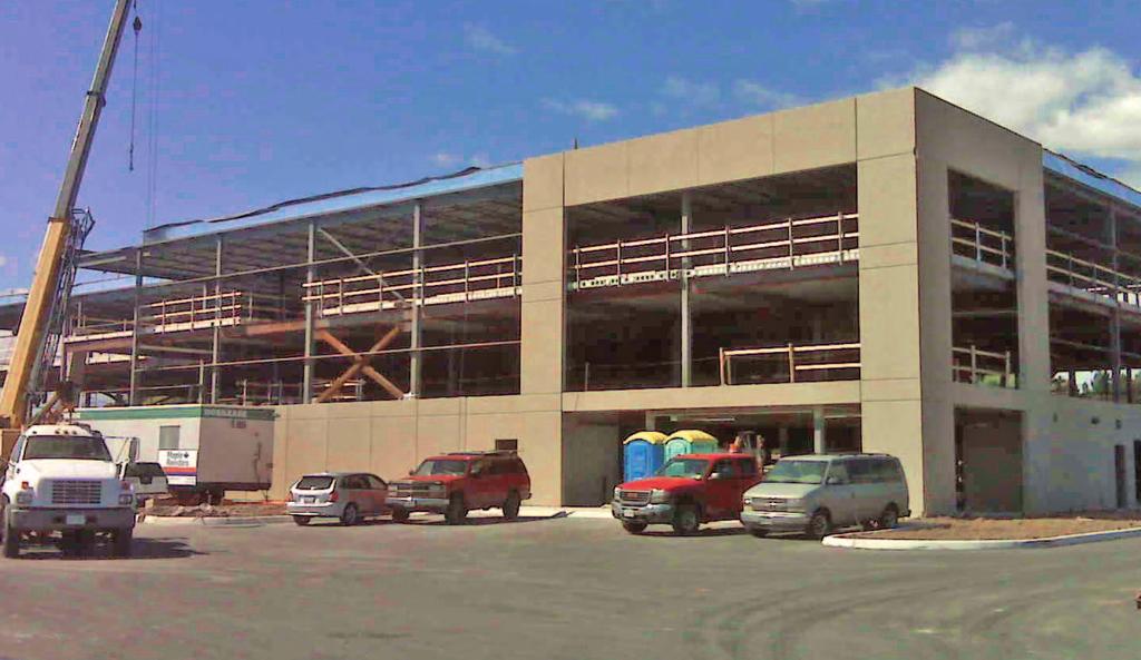
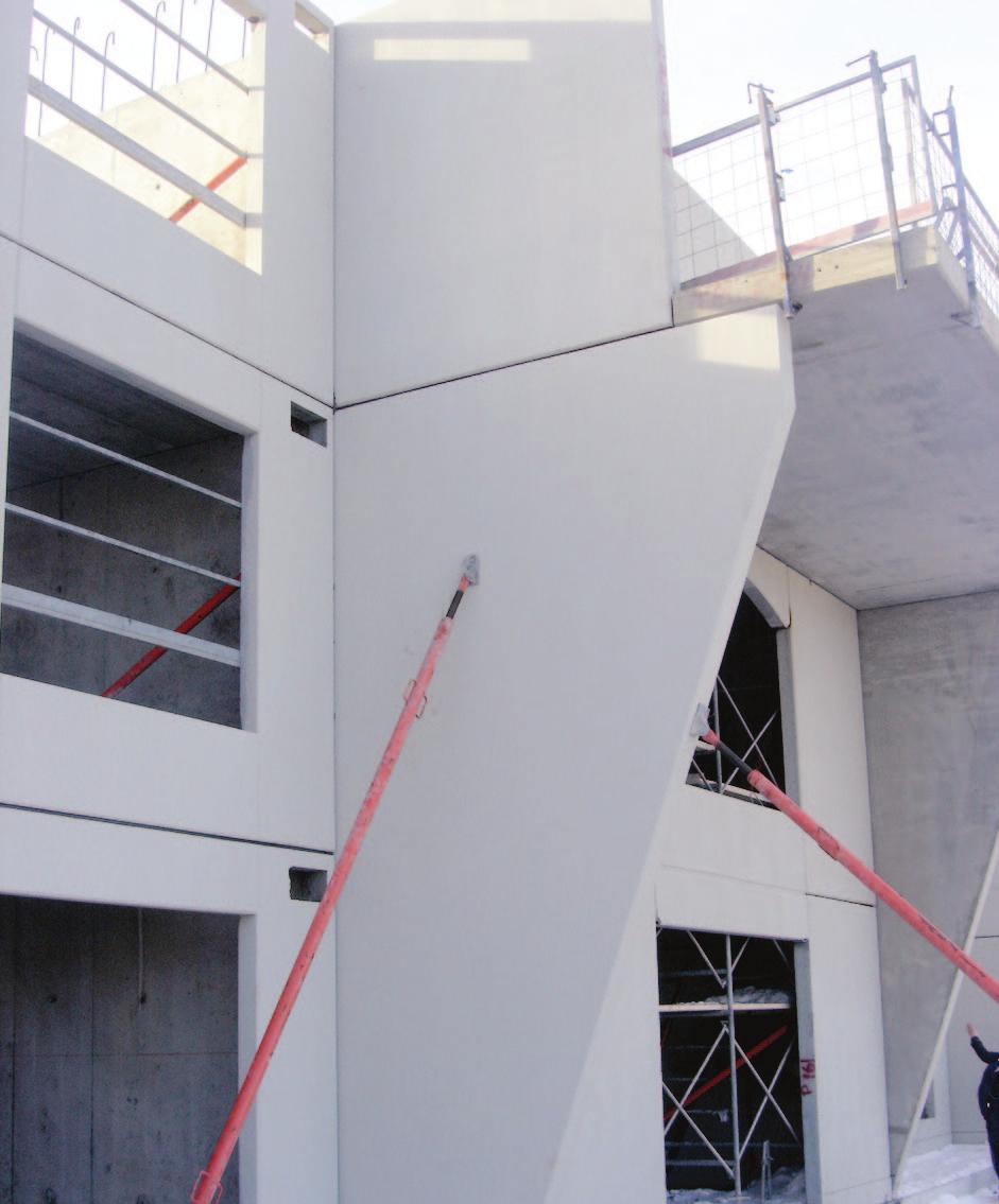
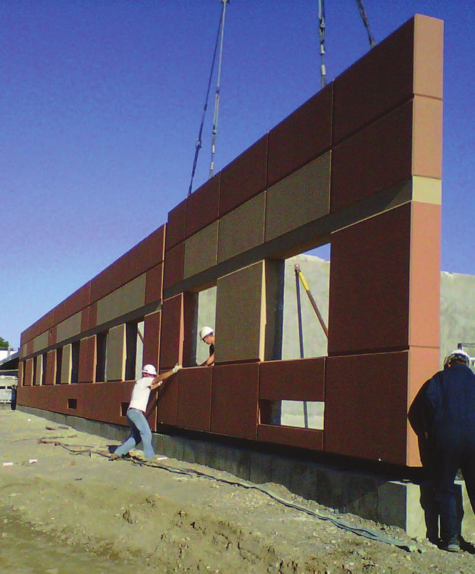
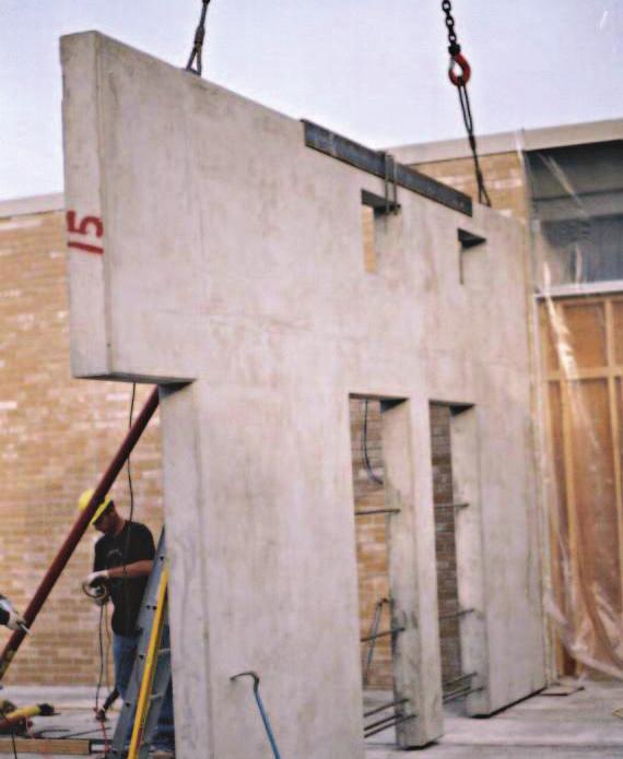
1 Wall Panels Structural wall panel Architectural wall panel Cladding wall panel Sandwich wall panel


2 Wall Panels Assorted styles and colours Reveals and other patterns Painted finish Bolted, welded and knife connections available
3 Wall Panel Sections STRAND DESIGN AS REQ D MIN. 90 1/2 X 1/2 CHAMFER (EXTERIOR ONLY) MAX= 13-0 Solid Cladding Panel STRAND DESIGN AS REQ D INSULATION 1/2 X 1/2 CHAMFER (EXTERIOR ONLY) MAX= 13-0 Insul. Cladding/Structural Panel STRAND DESIGN AS REQ D INSULATION 1/2 X 1/2 CHAMFER (EXTERIOR ONLY) MAX= 13-0 Insulated Ribbed Panel
4 T/O S PANEL HEAVY DUTY REGULAR PIPE BRACING C.I.P. CONTINUOUS CONCRETE BLOCK T/O FOOTING Structural Notes Design wind loads - 1.2kPa (25PSF) Install braces at 1220 (4-0 ) nominal spacing, at panels supported by knife connections the braces can be added to the supporting panels. Cast in place concrete to be minimum 30 MPa Braces to be anchored using 5 long 5/8 HILTI HUS-H screw anchor or approved equivalent installed in accordance with manufacturers recommendations Screw anchors to have minimum 3 embedment in wall panels Screw anchors to have minimum 4 embedment in cast in place concrete Bracing support during installation
5 PLASTIC SHIMS AND CONT. CAULKING ROD BOTH SIDES DOWEL DRILLED AND EPOXIED INTO PANEL PLATE CAST IN PANEL DESIGN WILL VARY PLASTIC SHIMS AND COIL LOOP INSERT DOWEL 2/PANEL U.N.O. POURED REINF. CONC. FOOTING/FOUNDATION WALL SCREWED ANCHOR OR EQUIVALENT CONNECTION POURED REINF. CONC. FOOTING/FOUNDATION WALL DP. HOLE DRILLED ON SITE WL01 Bottom connection cast in plate WL02 Bottom connection dowel connection METAL DECK ROOF PERCAST FOR STRUCTURAL CONNECTION PLASTIC SHIMS AND CONT. CAULKING ROD BOTH SIDES POURED REINF. CONC. FOOTING/FOUNDATION WALL DRYPACKS VOID SOLID SCREWED ANCHOR OR EQUIVALENT CONNECTION STRUCTURAL STEEL ELEV. FOR STRUCTURAL CONNECTION WL03 Bottom connection cast in plate WL04 Deck bearing back to back connection CAP FLASHING SPACER PLATES, COIL LOOP, WASHERS & SLOTTED PLATE CONT. ANGLE WELDED TO TOP OF STEEL CAP FLASHING METAL DECK ROOF WALL PANEL FOR STRUCTURAL CONNECTION STRUCTURAL BEAM STEEL STRUCTURE WL05 Lateral connection T/O panel WL06 Deck bearing / Beam connection

6 CONT. CAULKING AND BACKER COIL LOOP INSERT, WASHERS, BOLTS AND SLOTTED PLATE REMOVE INSERT LOCATIONS L-100x100x12x100LG ANGLE WL07 Exterior 90 corner connection WL08 Exterior 90 corner connection CONT. CAULKING AND BACKER L-100x100x12x100LG ANGLE COIL LOOP INSERT BAR W/2 LG. THREAD ONE END COIL LOOP INSERT, WASHERS, BOLTS AND SLOTTED PLATE REMOVE PLATE LOCATION 13mm RECESS WL09 Intersecting 90 corner connection WL10 Exterior 90 corner connection COIL LOOP INSERT, WASHERS, BOLTS AND SLOTTED PLATE 13mm CHAMFER 13mm CHAMFER COIL LOOP INSERT, WASHERS, BOLTS AND SLOTTED PLATE REMOVE INSERT LOCATIONS WL11 Panel to panel connection WL12 Panel to panel vertical
7 FROM PANEL EDGE FROM PANEL EDGE CONNECTION OF DOOR TO PANEL 13mm WIDE DRIP JOINT TREATMENT DOOR AND FRAME MAN DOOR G.C. NOTE: ALL MAN DOORS (NOT BY STUBBE S) 13 x13 CHAMFER MAN DOOR G.C. NOTE: ALL MAN DOORS (NOT BY STUBBE S) WL13 Panel head of man door (top view) WL14 Panel head of man door (side view) 13x13 CHAMFER WINDOW, FRAME AND CAULKING FROM PANEL EDGE O.H. DOOR CAST IN PLATE FROM PANEL EDGE CONNECTION OF BENT PLATE TO PANEL PLATE OH DOOR ELEVATION 1 WL15 Panel window sill on exterior panels WL16 Door O.H. door #1 O.H. DOOR AND TRACK SUPPLIED CONNECTION DESIGN CAST IN PLATE WINDOW, FRAME AND CAULKING STRUCTURAL COLUMN CONNECTION OF WINDOWS / DOOR TO PANEL SLOTTED ANGLE THREADED ROD GARAGE DOOR OPENING ELEVATION 2 HALFEN ANCHOR (VERTICAL) PLASTIC SHIMS WL17 Door O.H. door #2 WL18 Panel to column connection
8 KNIFE PLATE CAST INTO PANEL ENSURE ALL KNIFES ARE SHIMMED AND DRYPACKED W/NON SHRINK GROUT KNIFE PLATE CAST INTO PANEL KNIFE PLATE CAST INTO PANEL STEEL BEAM STEEL BEAM KNIFE PLATE CAST INTO PANEL BEARING ANGLE BEARING ANGLE WL19 Knife connection to beam WL20 Knife connection to ADJACENT PANEL SPACER PLATES, COIL LOOP, WASHERS AND SLOTTED PLATE CONT. ANGLE WELDED TO TOP OF STEEL REVEAL SIZE AND DESIGN PER CONTACT STEEL BEAM WL21 Laterial hung panel WL22 Reveal locations and profile CAP FLASHING SCUPPER METAL DECK ROOF CAP FLASHING SCUPPER STEEL STRUCTURE FOR STRUCTURAL CONNECTION METAL DECK ROOF WL23 Scupper detail #1 WL24 Scupper detail #2
9 Wall Panel Specifications 1. General: a. Included: i. Precast Wall Panels 1. Architectural & Structural Panels. 2. Sandwich & Cladding styles. ii. Structural connections. iii. Backer rod and caulking of panel joints. 2. Reference Material: a. CSA A : Precast Concrete Material & Construction. b. Precast Concrete Institute (PCI): Manual on Design of Connections for Precast. c. Precast Concrete Institute (PCI): Design Handbook Precast & Prestressed Concrete. 3. Shop Drawings: a. Approval drawings will require a review by the Contractor & Design Firms under contract of each project. Discrepancies, questions & verification of design is required and returned in writing prior to commencement of production. b. Production drawings will bear a signed and sealed Engineer stamp, slab locations, identification marks, connection details, dimensions, openings larger than 6 in size, loadings and other relative information. 4. Quality Assurance: a. Conformity to PCI manual on design of connection for Precast Prestressed Concrete, PCI Design Handbook Precast & Prestressed Concrete, CSA A Accessories: a. Shim pads: Plastic or steel to assist transfer of loads. b. Cast in inserts / plates or similar relevant to remainder of structure. c. Connections (i.e. knife, bolted, welded) between panel units. 6. Finishes: a. Steel form. b. Troweled. c. Sandblast. d. Ribbed pattern. e. Painted (with sand additive option). f. Exposed aggregate (vary with availability contact Stubbes for current options). g. Colours (vary with availability contact Stubbes for current options). 7. Installation: a. Install panels with corresponding identification mark as indicated on production / shop drawing. b. Ensure connections provided as detailed on production / shop drawing. c. Backer rod and caulking of joints between precast panels and foundation. 8. Excluded items related to precast and installation: a. Drypacking / infill of gap between precast and structure. b. Perimeter caulking between precast and structure (other than foundation). c. Winter heat / protection from weather conditions. d. Site / field dimensions (Contractor and Project Designers responsible to provide information during shop drawing approval).
WCU ALUMNI TOWER MASONRY & ENVELOPE REPAIRS
 SCO #: 8-8-0 TABLE OF CONTE COV DESCRIPTION COVER SHEET ALUMNI TOWER ELEVATIONS & PLAN VIEWS REPAIR DETAILS - M TO REPAIR DETAILS - TO M0 & C TO REPAIR DETAILS - A & F TO F VICINITY MAP ALUMNI TOWER ALUMNI
Nortrax Section David Manchester Road, Ottawa NON-STRUCTURAL METAL FRAMING 16 May 2014 Page 1
 16 May 2014 Page 1 PART 1 GENERAL 1.1 DESCRIPTION This section specifies steel studs wall systems, shaft wall systems, ceiling or soffit suspended or furred framing, wall furring, fasteners, and accessories
SPECIAL NOTES: EXCLUSIONS: THE FOLLOWING ITEMS ARE NOT SUPPLIED - SEE SEPARATE SAMPLES FOR GLASS MAKE UP.
 SPECIAL NOTES: - SEE SEPARATE SAMPLES FOR GLASS MAKE UP. A/C ACCESS CONTROLLED A.F.F. C L B.O.M. DIM. D.L.O. D.L. D.O. EL. F.D. F.F. G.C. ABOVE FINISHED FLOOR BOTTOM OF MULLION CENTER LINE DIMENSION DAYLIGHT
SECTION NON-STRUCTURAL METAL FRAMING
 SECTION 09 22 16 PART 1 - GENERAL 1.1 DESCRIPTION A. This section specifies steel studs wall systems, shaft wall systems, ceiling or soffit suspended or furred framing, wall furring, fasteners, and accessories
BROCHURE. Steel Forming System. A durable, all-steel forming system that is ideal for pier caps and self-spanning applications. DAYTONSUPERIOR.
 Max-A-Form Steel Forming System BROCHURE A durable, all-steel forming system that is ideal for pier caps and self-spanning applications. DAYTONSUPERIOR.COM Max-A-Form System Design The Max-A-Form Forming
Connection Design Assistance Manual
 Connection Design Assistance Manual Architectural Precast Concrete Glass Fiber Reinforced Concrete Cast Stone Architectural Precast Association 6710 Winkler Road, Suite 8 Fort Myers, FL 33919 Phone: 239-454-6989
 SPECIFICATIONS PRECAST PRESTRESSED CONCRETE PART 1 GENERAL 1.6.2.5 Openings, inserts and related reinforcement 1.6.3 Each drawing submitted to bear stamp of 1.1 Related Work qualified Professional Engineer
SECTION ARCHITECTURAL PRECAST CONCRETE. C. Section Joint Sealers: Perimeter joints with sealant and backing.
 SECTION 03451 ARCHITECTURAL PRECAST CONCRETE PART 1 GENERAL 1.01 SECTION INCLUDES A. Architectural precast concrete wall panels; with integral insulation. B. Supports, anchors, and attachments. C. Intermediate
SECTION FABRICATED ENGINEERED STRUCTURES. A. Pre-engineered, shop-fabricated structural steel building with formed purlin framing.
 PART 1 GENERAL 1.1 RELATED DOCUMENTS SECTION 13 34 00 FABRICATED ENGINEERED STRUCTURES A. Drawings and general provisions of the Contract, including General and Supplementary Conditions and Division 1
SECTION PRECAST STRUCTURAL PRETENSIONED CONCRETE
 PART 1 - GENERAL 1.1 DESCRIPTION: SECTION 03 41 33 PRECAST STRUCTURAL PRETENSIONED CONCRETE SPEC WRITER NOTE: Delete between //--// if not applicable to project. Also delete any other item or paragraph
Garage Beam System DAYTONSUPERIOR.COM FORMING. For Post-Tensioned Beam and Slab Parking Structures
 Garage Beam System For Post-Tensioned Beam and Slab Parking Structures FORMING The Garage Beam System is a complete forming system designed specifically for post-tensioned beam and slab multi-story parking
Stone and Masonry Veneer
 Stone and Masonry Veneer R703.7 Stone and masonry veneer, general. Stone and masonry veneer shall be installed in accordance with this chapter, Table R703.4 and Figure R703.7. These veneers installed over
COMMONWEALTH OF PENNSYLVANIA DEPARTMENT OF TRANSPORTATION BUREAU OF DESIGN
 GENERAL NOTES DESIGN TABLE NOTES INDEX OF SHEETS 1. ALL DIMENSIONS ARE IN MILLIMETERS UNLESS OTHERWISE NOTED. U.S. CUSTOMARY UNITS IN ( ) PARENTHESIS.. ALL "DESIGN" METRIC UNITS INDICATED ARE SOFT CONVERTED
SECTION PRECAST CONCRETE COVER SYSTEM
 SECTION 13500 PRECAST CONCRETE COVER SYSTEM PART 1 GENERAL 1.1 SYSTEM DESCRIPTION A. Design Criteria: 1. Precast manufacturer shall be responsible for structural design of individual precast components,
Precast Wall Panel Design. By Edward Losch, PE, SE
 Precast Wall Panel Design By Edward Losch, PE, SE What is a Precast Concrete Sandwich Wall Panel? Typical Precast Concrete Sandwich Wall Panel Long-Line Form Wythe(s) Prestressed Trucked & Erected (Non-loadbearing)
Requirements for Measuring and Pricing of Structural Concrete
 Requirements for Measuring and Pricing of Structural Concrete October 2016 TRANSPORT INFRASTRUCTURE IRELAND (TII) PUBLICATIONS About TII Transport Infrastructure Ireland (TII) is responsible for managing
SECTION ALUMINUM-FRAMED ENTRANCES AND STOREFRONTS
 SECTION 08 4113 ALUMINUM-FRAMED ENTRANCES AND STOREFRONTS PART 1 GENERAL 1.1 SUMMARY A. Section Includes: 1. Aluminum entrance doors and frames. 2. Glass infill panels. 3. Door hardware. B. Related Sections:
Structural Tests and Special Inspections Form. Inspection of Fabricators (1704.2)
") Inspection of Fabricators (1704.2) Furnish inspection reports (1704.2.1) - Fabricators that have not been approved Provide a Certificate of Compliance (1704.2.2) - Approved Fabricators Steel Construction
Inspection of Fabricators (1704.2) Furnish inspection reports (1704.2.1) - Fabricators that have not been approved Provide a Certificate of Compliance (1704.2.2) - Approved Fabricators Steel Construction
SECTION VIBRATION AND SEISMIC CONTROLS FOR HVAC PIPING AND EQUIPMENT
 SECTION 230548 - VIBRATION AND SEISMIC CONTROLS FOR HVAC PIPING AND EQUIPMENT PART 1 - GENERAL 1.1 RELATED DOCUMENTS A. Drawings and general provisions of the Contract, including General and Supplementary
Steel Forming System BROCHURE. A durable, all-steel forming system that is ideal for pier caps and self-spanning applications.
 Max-A-Form Steel Forming System BROCHURE A durable, all-steel forming system that is ideal for pier caps and self-spanning applications. Max-A-Form System Design The Max-A-Form Forming System combines
Installing DELTABEAM. Installation of DELTABEAM. Deliveries. Storage on-site
 Installing DELTABEAM Installation of DELTABEAM These DELTABEAM installation instructions are intended to complement the project s erection plan. Peikko s technical support can help with the erection plan
Anchor bolts ASTM F1554, Gr. 36 Wide flange beams ASTM A992, Fy = 50 ksi Misc. structural steel ASTM A36, Fy = 36 ksi
 STRUCTURAL NOTES MATERIAL STRENGTHS Structural Steel Reinforcing Steel Concrete Masonry Structural Lumber Anchor bolts ASTM F1554, Gr. 36 Wide flange beams ASTM A992, Fy = 50 ksi Misc. structural steel
STATEMENT OF SPECIAL INSPECTION FORM
 Project Title: Permit #: Project Address: STATEMENT OF SPECIAL INSPECTION FORM This Statement of Special Inspections is submitted in fulfillment of the requirements of CBC Sections 1704 and 1705. Special
SECTION VIBRATION CONTROLS FOR HVAC PIPING AND EQUIPMENT
 SECTION 230548 - PART 1 - GENERAL 1.1 SUMMARY A. This Section includes the following: 1. Elastomeric Isolation pads. 2. Elastomeric Isolation mounts. 3. [Freestanding] [Restrained] [Freestanding and restrained]
Elevated Slab Sequence
 Elevated Slab Sequence The following group of photos shows the sequence for installa4on of a one- way elevated slab. (Slab & Beam with Reinforcing & Post- Tensioning) Columns Placed & Form Support (Scaffolding)
SECTION FABRICATED PRE-ENGINEERED PRECAST CONCRETE STRUCTURES. 10 x 12 PRECAST CONCRETE BUILDING EASI-SET FIELD ASSEMBLED
 SECTION 13 34 00 FABRICATED PRE-ENGINEERED PRECAST CONCRETE STRUCTURES SECTION 1 GENERAL 1.1 WORK INCLUDED 10 x 12 PRECAST CONCRETE BUILDING EASI-SET FIELD ASSEMBLED Contractor to furnish a precast concrete
HOLDOWN & STRAP SCHEDULE
 SHEAR WALL SCHEDULE STRUCTURAL DESIGN CRITERIA GOVERNING CODE SOIL BEARING PRESSURE HOLDOWN & STRAP SCHEDULE MARK SHEATHING SHEATH BOTH SIDES NAILS EDGE SPACING NOTES MARK SW 7/" OSB NO 8d " OC - A SW
Installation GUIDE STEEL DECKING SOLUTIONS FOR CONCRETE SLABS
 STEEL DECKING SOLUTIONS FOR CONCRETE SLABS Installation GUIDE Please take time to read this Truedek Installation Guide prior to site work commencing. It contains important delivery and installation information
SECTION. Trellis and Pergola
 10 73 00 SECTION Trellis and Pergola PART 1 GENERAL 1.1 SECTION INCLUDES A. Pre-engineered, pre-finished Pergola system. B. Pre-engineered, pre-finished Trellis system. 1.2 RELATED SECTIONS A. Section
1. Base plates, setting plates and anchor rods for columns. 8. Lintels if connected to structural steel columns.
 PAGE 051200-1 SECTION 051200 PART 1 - GENERAL 1.1 RELATED DOCUMENTS A. Drawings and general provisions of the Contract, including General and Supplementary Conditions and Division 01 Specification sections,
INSTALLATION MANUAL KOCH
 INSTALLATION MANUAL KOCH TECHNICAL SYSTEMS GROUP PRE-FAB ACOUSTICAL/THERMAL PANELS AND ENCLOSURES GEORGE KOCH SONS, LLC TECHNICAL SYSTEMS GROUP 10 South Eleventh Avenue Evansville, Indiana 47744 812-465-9600
STRUCTURAL STEEL FRAMING
 SECTION 05 12 00 - STRUCTURAL STEEL FRAMING PART 1 - GENERAL 1.1 SUMMARY A. Section includes 1. Structural steel framing 2. Structural steel framing required for support and framing of rooftop mechanical
CONCRETE FORMWORK. .2 CSA , Supplement No.1 to CAN/CSA , Engineering Design in Wood. .4 CSA O151, Canadian Softwood Plywood.
 CITY OF BRAMPTON LANDSCAPE SPECIFICATIONS SECTION 03100-1 PART 1 GENERAL 1.1 Related Work.1 All Division 1 Specification Sections.2 Section 02233 Granular Base.3 Section 02311 Site Grading.4 Section 03200
Table of Contents. List of Drawings
 SCOPE OF WORK Hastings Stadium Exhibition Park, 81 London Road, Guelph, Ontario Structural and Maintenance Remedial Work Prepared For City of Guelph City Hall, 1 Carden Street, Guelph, ON N1H 3A1 Prepared
ThermaSteel Corporation ASSEMBLY MANUAL
 ThermaSteel Corporation ASSEMBLY MANUAL TABLE OF CONTENTS 1- INTRODUCTION 1.1 THERMASTEEL TM WALL PANELS 1.2 Drawing and Element Numbers 2- ASSEMBLY 2.1 Sequence of Assembly 2.2 Preparation of Foundation
SECTION WOOD FRAMING. A. Includes But Not Limited To 1. Furnish and install wood framing and blocking as described in Contract Documents.
 SECTION 06110 WOOD FRAMING PART 1 GENERAL 1.1 SUMMARY A. Includes But Not Limited To 1. Furnish and install wood framing and blocking as described in Contract Documents. B. Products Installed But Not Supplied
LymTal International, Inc.
 Iso-Flex Deck-Lock Installation Instructions Figure 1 (Parts Drawing) SPLIT SLAB/PLAZA DECK JOINT COVER SYSTEM Installation Instructions The following installation instructions are very important. Read
SECTION ALUMINUM WALKWAY COVERS. A. The requirements of Division 1 specifications shall apply to work specified in the section.
 SECTION 10 5300 ALUMINUM WALKWAY COVERS Part 1 General 1.01 Related Documents A. The requirements of Division 1 specifications shall apply to work specified in the section. 1.02 References A. International
SECTION STRUCTURAL PRECAST HOLLOW CORE SLABS
 PART 1 GENERAL 1.01 SCOPE OF WORK A. The Contractor shall furnish all labor, materials, equipment and incidentals to provide a complete structural precast hollow core slab system as shown on the Contract
Residential Wall Panel Installation
 Residential Wall Panel Installation Planning & System Parameters 1. Health & Safety Act 1992 The principle objects of the Health & Safety Employment Act 1992 (HSE Act) are to prevent harm to employees
#G445 Plans, 48'x28' x 10' detached garage with bonus room By SDS-CAD Specialized Design Systems
 Architectural asphalt shingles and horizontal True Wood 7" Reveal siding over structural panel. Nailing schedule is 6" on ends 12" on centers 6d nails. Trusses are engineered on Bonus attic trusses 24"
Custom 22' x 40' - 16' Tall Garage Plan #g227 By SDS-CAD Specialized Design Systems
 P O Box 34 Mendon, Utah Custom 22' x 40' - 16' Tall Garage Plan #g22 By Page 1 Title Page Page 2 Main Floor Plan Page 3 Foundation Plan Page 4 Elevation Views Page 5 Framing and Details Page 6 Typical
SECTION FABRICATED PRE-ENGINEERED PRECAST CONCRETE STRUCTURES. 10 x 12 PRECAST CONCRETE BUILDING EASI-SET PRE-ASSEMBLED
 SECTION 13 34 00 FABRICATED PRE-ENGINEERED PRECAST CONCRETE STRUCTURES SECTION 1 GENERAL 1.1 WORK INCLUDED 10 x 12 PRECAST CONCRETE BUILDING EASI-SET PRE-ASSEMBLED Contractor shall furnish a precast concrete
SECTION PRE-CAST CONCRETE BUILDING PREFABRICATED
 SECTION 13120 PRE-CAST CONCRETE BUILDING PREFABRICATED PART I - GENERAL 1.01 SUMMARY Contractor to furnish pre-cast, post-tensioned concrete transportable building. Building to be delivered and placed
Installation Instructions
 Installation Instructions 400SS Series Curtainwall 3056 WALKER RIDGE DR. NW, SUITE G WALKER, MI 49544 800-866-2227 dependable@tubeliteinc.com Revised June 2016 dependable@tubeliteinc.com Page 1 TABLE OF
Custom 30 x 48-14' Tall Garage Plan #g226 By SDS-CAD Specialized Design Systems
 P O Box 34 Mendon, Utah Custom 30 x 48-14' Tall Garage Plan #g226 By Page 1 Title Page Page 2 Main Floor Plan Page 3 Foundation Plan Page 4 Elevation Views Page 5 Framing and Details Page 6 Typical Section
GARAGE MAIN FLOOR PLAN
 12'-0" 4'-6" 3'-0" 4'-6" 3040 14'-0" LADDER LT LINE BUNK CABIN 11'-4" x 13'-4" 14'-0" BUILDING CONTRACTOR/HOME OWNER TO REVIEW AND VERIFY ALL DIMENSIONS, SPECS, AND CONNECTIONS BEFORE CONSTRUCTION BEGINS.
PROJECT: 4/30/14 DATE: REVISIONS: 6/10/14 7/28/14 11/3/14 11/12/14 11/14/14 OF 6
 4/30/14 C 7/31/2014 4'-6" RAMP TO EXISTING GRADE DRAWN: JW 11/12/2014 AS REQ'D 7'-10 1/2" 7'-10 1/2" 7'-10 1/2" 7'-10 1/2" 2'-0 1/2" 4'-10 1/2" 6" 3'-10" 3'-8" L2X2X1/8 @ 16" OC (TYP) L2X2X1/8 @ 16"
SPECIFICATIONS Section Cantilevered Walkway Cover
 Part 1: General 1.1 Related Documents SPECIFICATIONS Section 107301 Cantilevered Walkway Cover A. The requirements of Division 1 specifications shall apply to work specified in the section. 1.2 Engineering
SECTION TILT-UP PRECAST CONCRETE SANDWICH PANELS. A. Work includes, but is not limited to, the following:
 PART 1 GENERAL 1.01 SUMMARY SECTION 03460 TILT-UP PRECAST CONCRETE SANDWICH PANELS A. Work includes, but is not limited to, the following: 1. Architectural precast concrete sandwich wall panels. 2. Integral
Interior Hangers. Application
 Application Interior bridge deck hangers are typically fabricated using two heavy duty sheet metal end clips that have been electrically resistance welded to an appropriate sized wire or formed metal connecting
Chuck Brooks, P.E., P.Eng. C&S Engineers
 Chuck Brooks, P.E., P.Eng C&S Engineers 315-455-2000 cbrooks@cscos.com AGENDA INTRO BASICS KEY CONSIDERATIONS DESIGN CONSTRUCTION Questions to be Explored 1. Concrete Tiltup Panels are designed for the
A. Pre-engineered, pre-finished extruded aluminum Pavilions.
 10 73 00 SECTION Pavilions PART 1 GENERAL 1.1 SECTION INCLUDES A. Pre-engineered, pre-finished extruded aluminum Pavilions. 1.2 RELATED SECTIONS A. Section 03100 - Concrete Forms and Accessories. B. Section
STANDARDIZED STRUCTURES
 Q, QH & QL TOWERS 16.1 Q, QH, and QL Towers General Description The series includes three and four leg angle towers, which are suited for a variety of antenna mounting positions and load conditions. The
SECTION PRECAST CONCRETE BUILDING PREFABRICATED. ACI , "Building Code Requirements for Reinforced Concrete".
 SECTION 13120 PRECAST CONCRETE BUILDING PREFABRICATED PART I - GENERAL 1.01 SUMMARY Contractor to furnish precast concrete building. Building to be field erected on customer prepared crushed stone foundation
Smarter. Safer. Leaner.
 Smarter. Safer. Leaner. Fast Installation and Removal Decrease Leading Edge Exposure by 87% OSHA Compliant Versatile and Reusable Use Perimeter Protection Posts During Construction: At Building Perimeter
STANDARD RESIDENTIAL DECK DETAILS
 STANDARD RESIDENTIAL DECK DETAILS GUARD DECKING FLASHING OVER LEDGER BOARD EXISTING HOUSE FLOOR CONSTRUCTION GUARD POST ATTACHEMENT LEDGER BOARD ATTACHMENT TO HOUSE RIM JOIST JOIST BEAM FOOTING JOIST TO
Mezzanines By Design Page 1
 SECTION 05120 STRUCTURAL STEEL PART 1 - GENERAL 1.1 RELATED DOCUMENTS A. Drawings and general provisions of the Contract, including General Conditions and Division 1 apply to this Section. 1.2 SUMMARY
SECTION TILT-UP PRECAST CONCRETE. A. Work includes, but is not limited to, the following:
 SECTION 03470 TILT-UP PRECAST CONCRETE PART 1 GENERAL 1.01 SUMMARY A. Work includes, but is not limited to, the following: 1. Precast wall panels. 2. Forms and casting beds. 3. Concrete. 4. Reinforcing
SPECIAL INSPECTION AGREEMENT FORM
 CITY OF TRACY DEVELOPMENT & ENGINEERING SERVICES 333 CIVIC CENTER PLAZA, TRACY, CA 95376 P :( 209) 831-6400 F :( 209) 831-6439 http://www.ci.tracy.ca.us SPECIAL INSPECTION AGREEMENT FORM Prior to issuance
GARAGE MAIN FLOOR PLAN
 BUILDING CONTRACTOR/HOME OWNER TO REVIEW AND VERIFY ALL DIMENSIONS, SPECS, AND CONNECTIONS BEFORE CONSTRUCTION BEGINS. SHED TO BE BUILT AS PER IRC, UBC OR CURRENT LOCAL CODE To the best of my knowledge
DIVISION 04 MASONRY. Section Title Number MASONRY Maintenance of Masonry Masonry Mortaring Masonry Accessories
 04 00 00 MASONRY 04 01 00 Maintenance of Masonry 04 01 20 Maintenance of Masonry 04 05 13 Masonry Mortaring 04 05 23 Masonry Accessories 04 20 00 UNIT MASONRY 04 21 00 Clay Unit and Brick Veneer 04 22
Design No. HI/BP PERIMETER FIRE BARRIER SYSTEM Hilti, Inc. ASTM E 2307 Table 1
 FIRESTOP JOINT SPRAY CFS-SP WB SILICONE JOINT SPRAY CFS-SP SIL F-RATING 2-HR. 2-HR. T-RATING -HR. -HR. APPLICATION THICKNESS PERIMETER FIRE BARRIER SYSTEM Hilti, Inc. ASTM E 2307 Table /8" WET FILM (/6"
See the IRC for additional information. See CPD-DS Information Bulletin 100 for Requirements for 1 & 2 Family Dwelling plan submittals.
 As a customer service initiative, the Kansas City, Missouri, City Planning and Development Department/Development Services, in cooperation with the Greater Kansas City Home Builders Association, has developed
TCC/SHORE TRANSIT BUS MAINTENANCE FACILITY - PHASE II
 SECTION 052100 - STEEL JOISTS PART 1 - GENERAL 1.1 RELATED DOCUMENTS: A. Drawings and General Provisions of the Contract, including General and Supplementary Conditions and Division 1 Specification Sections
SECTION MANUAL FOUR FOLD DOORS MODEL 38 DECORATIVE PANEL DESIGN
 SECTION 08350 MANUAL FOUR FOLD DOORS MODEL 38 DECORATIVE PANEL DESIGN PART 1 GENERAL 1.01 RELATED DOCUMENTS A. Drawings and general provisions of the Contract, including General and Supplementary Conditions
ICBO Evaluation Service, Inc Workman Mill Road, Whittier, California
 Reissued June 1, 2002 ICBO Evaluation Service, Inc. 5360 Workman Mill Road, Whittier, California 90601 www.icboes.org Filing Category: DESIGN Concrete DURISOL WALL FORMS FOR CONCRETE CONSTRUCTION DURISOL
Art Mould Plastics "SUPPORTING THE REINFORCING CONCRETE INDUSTRY SINCE 1966"
 Art Mould Plastics "SUPPORTING THE REINFORCING CONCRETE INDUSTRY SINCE 1966" 1 of 10 Table of Contents Individual Support Chairs Linden Chairs. 3 Sand Plates 3 X-Chairs.. 4 Rod Spacers.. 4 Type-A. 5 Sand
DOCUMENT ADDENDUM SCHOOL DISTRICT OF HOLMEN HIGH SCHOOL AND MIDDLE SCHOOL SECURE ENTRANCES HOLMEN, WISCONSIN HSR PROJECT NO.
 DOCUMENT 00 90 00 ADDENDUM ADDENDUM NO. [] Date: March, 08 RE: FROM: SCHOOL DISTRICT OF HOLMEN HIGH SCHOOL AND MIDDLE SCHOOL SECURE ENTRANCES HOLMEN, WISCONSIN 466 HSR PROJECT NO. 707 HSR Associates, Inc
Detached Garages and Building Permits. 1 and 2 Family Dwellings
 Detached Garages and Building Permits 1 and 2 Family Dwellings Why do I need a permit? The City of Minneapolis adopts the State of Minnesota Building Code (MNSBC) and its associated state statutes and
Sport Systems Canada Inc. Section Angle Framed Bleachers Page 1
 Page 1 Part 1 GENERAL.1.1 Section Includes.1 Design, fabrication, engineering, and installation of continuous angle framed bleacher assembly, including the following:.1 Foundations.2 Galvanized steel framing
CONCRETE TECHNOLOGY CORPORATION
 PRECAST, PRESTRESSED HOLLOW CORE SLABS DESIGN CRITERIA & SPAN-LOAD CHARTS Introduction 2 Design Criteria for Development of the Span-Load Charts 2 Related Publications 3 Manufacturing Tolerances 4 8" Bare
7. New railings for existing buildings shall be designed to match any existing railings unless there is a compelling reason for change.
 Division 05. Metals 05 50 00. Metal Fabrications 05 50 00. Roof - Fall Protection The contractor shall provide a horizontal cable lifeline system on steel posts complying with applicable regulatory requirements.
OAK TREE LIQUOR STORE
 DRAWING LIST ARCHITECTURAL A000 - COVER SHEET D0 - DEMOLITION PLANS & ELEVATIONS A0 - PLANS, ELEVATIONS & DETAILS A40 - BUILDING S A40 - BUILDING S ARCHITECT: Engineering (00) Inc. 6 Great George Street,
Module number 3 provides an on-line, self-paced training seminar on chapter 4, foundations and chapter 5, floors from the residential code of ohio.
 Module number 3 provides an on-line, self-paced training seminar on chapter 4, foundations and chapter 5, floors from the residential code of ohio. 1 This chapter sets forth the prescriptive requirements
TABLE OF CONTENTS. 1.0 INTRODUCTION 1.1 Greenstone Structural Engineered Panels 1.2 Drawing and Element Numbers
 version 2.5 updated as of 08.04.2017 2 TABLE OF CONTENTS 1.0 INTRODUCTION 1.1 Greenstone Structural Engineered Panels 1.2 Drawing and Element Numbers 2.0 ASSEMBLY 2.1 Sequence of Assembly 2.2 Preparation
GARAGE MAIN FLOOR PLAN
 BUILDING CONTRACTOR/HOME OWNER TO REVIEW AND VERIFY ALL DIMENSIONS, SPECS, AND CONNECTIONS BEFORE CONSTRUCTION BEGINS. SHED TO BE BUILT AS PER IRC, UBC OR CURRENT LOCAL CODE To the best of my knowledge
SECTION HANGERS AND SUPPORTS FOR ELECTRICAL SYSTEMS
 SECTION 26 05 29 HANGERS AND SUPPORTS FOR ELECTRICAL SYSTEMS PART 1 GENERAL 1.1 DESCRIPTION A. Scope: 1. CONTRACTOR shall provide all labor, materials, equipment, and incidentals as shown, specified, and
MAIN FLOOR PLAN. #G x 14 x 8 Shed - Chicken Coop By SDS-CAD Specialized Design Systems 10'-0" 3'-0" 1'-0" 14'-0" 14'-0" 1'-0" 6'-0" 3'-0"
 10'-0" BUILDING CONTRACTOR/HOME OWNER TO REVIEW AND VERIFY ALL DIMENSIONS, SPECS, AND CONNECTIONS BEFORE CONSTRUCTION BEGINS. BARN TO BE BUILT AS PER LOCAL CODE REQUIREMENTS 14'-0" BWP BWP BWP ABWP 101
SPECIAL INSPECTION AND OBSERVATION PROGRAM City of Walnut Creek Building Division. Project Address:
 SPECIAL INSPECTION AND OBSERVATION PROGRAM City of Walnut Creek Building Division Permit Application #: Project Address: Purpose: To meet the requirements of City of Walnut Creek Municipal Code Section
SECTION HANGERS AND SUPPORTS FOR PLUMBING
 SECTION 22 05 29 HANGERS AND SUPPORTS FOR PLUMBING PART 1 - GENERAL 1.1 RELATED DOCUMENTS A. Drawings and general provisions of the Contract, including General and Supplementary Conditions and Division
Sheet Metal Flashing and Trim
 University of New Hampshire University of New Hampshire Scholars' Repository Division 07 Thermal and Moisture Protection Chapter 5 Technical Construction and Renovation Standards 1-25-2013 076200 - Sheet
TECHNICAL MANUAL. PEC Column Shoe. Heavy-duty Bolted Column Connections
 TECHNICAL MANUAL PEC Column Shoe Heavy-duty Bolted Column Connections Version: PEIKKO GROUP 09/2018 PEC Column Shoe For bolted column connections Advanced casting process with the help of standard accessories
TILT-UP PRECAST CONCRETE SANDWICH PANELS. A. Work includes, but is not limited to, the following:
 PART 1 GENERAL 1.01 SUMMARY SECTION 03460 TILT-UP PRECAST CONCRETE SANDWICH PANELS A. Work includes, but is not limited to, the following: 1. Architectural precast concrete sandwich wall panels. 2. Integral
The better way to build TM. Installation Manual NAILBASE PANELS
 The better way to build TM Installation Manual PANELS November 2018 SIPs Installation Manual Table of Contents Topics General Requirements................................... 3 Materials..............................................
Commercial Flashing Details
 This technical note illustrates many of the most common flashing details for commercial buildings. The purpose for flashing is to direct moisture to the exterior and in so doing, prevent moisture from
30 X 40 POLE BARN 12 HIGH SIDE WALLS 2-12 WIDE X 10 HIGH SECTIONAL GARAGE DOORS OPTIONAL WINDOWS DETAILS INCLUDED
 30 X 40 POLE BARN 12 HIGH SIDE WALLS 2-12 WIDE X 10 HIGH SECTIONAL GARAGE DOORS OPTIONAL WINDOWS DETAILS INCLUDED 3 ENTRY DOOR METAL ROOF METAL SIDING GABLE ROOF, 4/12 PITCH INDEX PAGE DESCRIPTION 1 FRONT
DIVISION 5 - STRUCTURAL STEEL AND IRON WORK
 DIVISION 5 - STRUCTURAL STEEL AND IRON WORK SECTION 05100 STRUCTURAL METAL FRAMING PART 1.00 GENERAL 1.01 SCOPE OF WORK A. Work Included: 1. 2. Structural steel complete in place. Steel joists complete
D D TYPE A1, A2 & B MICHIGAN DEPARTMENT OF TRANSPORTATION 5-40 CONNECTION. L4" x 4" x 3/8" Brace. C8 x 4.25 Strut. WT9 x 17.5.
 Sign length minus Adjust to avoid interference with sign legend A Deck fascia A 6" Equal Equal 6" Sign length (L) varies 6 to 12 PLAN 0 CONNECTION (DECK FASCIA) Angle connection assembly F Face of concrete
SECTION ORNAMENTAL ALUMINUM FENCING
 SECTION 032300 ORNAMENTAL ALUMINUM FENCING PART 1 - GENERAL 1.1 RELATED DOCUMENTS A. Drawings and general provisions of the Contract, including General and Supplementary Conditions and Division 01 Specification
ACCESSORY STRUCTURES (Garages/Sheds) BUILDING AND ZONING REQUIREMENTS (REVISED 4/21/16)
 BUILDING AND ZONING REQUIREMENTS (REVISED 4/21/16)") ACCESSORY STRUCTURES (Garages/Sheds) BUILDING AND ZONING REQUIREMENTS (REVISED 4/21/16) NOTE: No building permit shall be issued for the construction of more than one (1) detached accessory building on
ACCESSORY STRUCTURES (Garages/Sheds) BUILDING AND ZONING REQUIREMENTS (REVISED 4/21/16) NOTE: No building permit shall be issued for the construction of more than one (1) detached accessory building on
Method of Measurement for Road Works Series MM Structural Concrete
 Method of Measurement for Road Works Series MM 1700 - CC-RMP-01700 December 2013 CC Construction & Commissioning Standards TRANSPORT INFRASTRUCTURE IRELAND (TII) PUBLICATIONS About TII Transport Infrastructure
METALS Commissioning of Metals Structural Steel Framing Steel Studs... 2
 ~ 05-1 ~ 05 00 00 Metals 05 00 00 METALS... 2 05 08 00 Commissioning of Metals... 2 05 12 00 Structural Steel Framing... 2 05 12 30 Steel Studs... 2 05 45 00 METAL SUPPORT ASSEMBLIES... 2 05 50 00 METAL
SECTION STEEL JOIST FRAMING
 PART 1 - GENERAL 1.1 DESCRIPTION SECTION 05 21 00 1. Use this section only for NCA projects. 2. Delete between //---// if not applicable to project. Also delete any other item or paragraph not applicable
Chapter 32 - Garage. June 2015 Garages 32-1
 Chapter 32 - Garage Contents Chapter 32 - Garage... 32-1 Foundation... 32-3 Walls... 32-3 Roof Framing... 32-4 Roofing... 32-4 Exterior Dow Board... 32-5 Doors... 32-5 Siding... 32-5 Gutters... 32-6 Painting...
Custom 24 x 26 Garage Plan Roy Hartmann Plan #g218 By SDS-CAD Specialized Design Systems CLIENT
 P O Box 34 Mendon, Utah Custom 24 x 26 Garage Plan Plan #g218 By Page 1 Title Page Page 2 Main Floor Plan Page 3 Foundation Plan Page 4 Elevation Views Page 5 Framing and Details Page 6 Typical Section
SECTION HANGERS AND SUPPORTS FOR PLUMBING PIPING AND EQUIPMENT. A. ASME B31.1 (American Society of Mechanical Engineers) - Power Piping
 - Power Piping") SECTION 22 05 29 HANGERS AND SUPPORTS FOR PLUMBING PIPING AND EQUIPMENT PART 1 - GENERAL 1.1 SUMMARY A. Section includes pipe and equipment supports, hangers, anchors, bases sleeves and the sealing of
SECTION 22 05 29 HANGERS AND SUPPORTS FOR PLUMBING PIPING AND EQUIPMENT PART 1 - GENERAL 1.1 SUMMARY A. Section includes pipe and equipment supports, hangers, anchors, bases sleeves and the sealing of
THRESHOLD INSPECTION SPECIAL INSPECTION PLAN. Evangel Temple Addition
 Page 1 of 11 THRESHOLD INSPECTION SPECIAL INSPECTION PLAN PROJECT: Addition OWNER: ARCHITECT: Brennfoerder Architectural Services STRUCTURAL ENGR: Tappana Ondrick Structural Engineers DATE: Sept. 4, 2018
KARRIER PANEL - BRICK
 KPH-DS-01-BRICK KPH-PJ-01-BRICK KPH-PJ-02-BRICK KPH-PJ-03-BRICK KPH-BS-01-BRICK KPH-BS-02-BRICK KPH-BS-03-BRICK KPH-OC-01-BRICK KPH-FO-01-BRICK KPH-FO-02-BRICK KPH-FO-03-BRICK KPH-FO-04-BRICK KPH-FO-05-BRICK
SECTION VIBRATION AND SEISMIC CONTROLS FOR ELECTRICAL SYSTEMS
 SECTION 260548 - VIBRATION AND SEISMIC CONTROLS FOR ELECTRICAL SYSTEMS PART 1 - GENERAL 1.1 SUMMARY A. Section includes: 1. Isolation pads. 2. Spring isolators. 3. Restrained spring isolators. 4. Channel