Laboratory Investigation of Glass Fiber Reinforced Polymer Bridge Slab to Reinforced Concrete Parapet Connection Details
|
|
|
- Silas Webb
- 6 years ago
- Views:
Transcription
1 Lehigh University Lehigh Preserve ATLSS Reports Civil and Environmental Engineering Laboratory Investigation of Glass Fiber Reinforced Polymer Bridge Slab to Reinforced Concrete Parapet Connection Details Clay Naito Seoksoon Lee Fyiad Constantine Follow this and additional works at: Recommended Citation Naito, Clay; Lee, Seoksoon; and Constantine, Fyiad, "Laboratory Investigation of Glass Fiber Reinforced Polymer Bridge Slab to Reinforced Concrete Parapet Connection Details" (2003). ATLSS Reports. ATLSS report number 03-27:. This Technical Report is brought to you for free and open access by the Civil and Environmental Engineering at Lehigh Preserve. It has been accepted for inclusion in ATLSS Reports by an authorized administrator of Lehigh Preserve. For more information, please contact

2 PITA Project PIT Laboratory Investigation of Glass Fiber Reinforced Polymer Bridge Slab to Reinforced Concrete Parapet Connection Details FINAL REPORT By Clay Naito, Principal Investigator Seoksoon Lee, Graduate Student Researcher Fyiad Constantine, Undergraduate Researcher December 18, 2003 ATLSS REPORT NO ATLSS is a National Center for Engineering Research on Advanced Technology for Large Structural Systems 117 ATLSS Drive Bethlehem, PA Phone: (610) Fax: (610) inatl@lehigh.edu
3 1. TABLE OF CONTENTS 1. Table of Contents List of Figures Abstract Background Overview Existing Bridge Design FRP Bridge Deck System AASHTO Parapet Design Experimental Research Program Testing Methodology Load Rate Test Configuration and Boundary Conditions Phase 1 As-Built System Performance Specimen Configuration Phase 1 Material Properties Concrete FRP Reinforcement Phase 1 Global Response Load Deformation Response Observed Progression of Failure Energy Adsorption Phase 1 Local Deformation Phase 1 Local Response Buckling of FRP Slab Web Slip Between Bottles Reinforcement Behavior FRP Slab Flexural Response Pull-Out Test for Embedded Reinforcement in FRP Slab Phase 1 Conclusions Phase 2 Anchorage Improvements Page 1
4 9.1. Specimen Configuration Anchorage Detail Wearing Surface Phase 2 - Material Properties Concrete FRP Reinforcement Phase 2 Global Response Measurement Global Results Phase 2 Local Response Strain Instrumentation Buckling of FRP Slab Webs Intra Bottle Slip Reinforcement Behavior FRP Slab Flexural Response Phase 2 Conclusions Phase 3 Rehabilitation Measures Specimen Configuration Material Properties Phase 3 Global Response Progression of Failure Energy Adsorption Phase 3 Conclusions Parapet Acceptance Conclusions Future Work References APPENDIX 1 Concrete Mix Design Acknowledgements Page 2
5 2. LIST OF FIGURES Figure 1: Dubois Creek FRP Slab Bridge... 8 Figure 2: Bridge configuration Figure 3: Railing design requirements (From AASHTO 2000) Figure 4: Finite element model of test specimen with applied uniform displacement of 0.05-in. (Szz shown) Figure 5: Finite element model of bridge with transverse load Figure 6: Force in tensile reinforcement from FE analysis Figure 7: System modeling Figure 8: Subassembly configuration Figure 9: FRP slab configuration for test specimens Figure 10: Configuration of FRP slab skin on specimen Figure 11: Specimen A Figure 12: Specimen B Figure 13: Parapet configuration for specimen A and B Figure 14: Specimen after fabrication of parapet Figure 15: FRP slab for specimen B close-up Figure 16: Measured FRP slab A and B surface profile Figure 17: Parapet concrete strength of specimen A and B Figure 18: Embedded reinforcement coupler Figure 19: Displacement components Figure 20: Global instrumentation Figure 21: Global Load-Deformation Figure 22: Failure progression Figure 23: Energy due to response Figure 24: Component deformations A Figure 25: Component deformations B Figure 26: Gap opening at face of parapet Figure 27: FRP slab strain gage layout Figure 28: Parapet strain gage layout Figure 29: Web loading Figure 30: Buckling example Figure 31: Vertical web strain Page 3
6 Figure 32: Intra-bottle slip Figure 33: Strain in reinforcement on compression face Figure 34: Strain in tensile reinforcement Figure 35: FRP slab-parapet section (A) Figure 36: FRP slab section (A) Figure 37: Reinforcement anchorage specimen A Figure 38: Visible slip of reinforcement in specimen A and B Figure 39: Top flange fracture surface Figure 40: External web fracture surface Figure 41: Longitudinal strain in top flange of FRP slab Figure 42: Longitudinal strain in bottom flange of FRP slab Figure 43: Configuration of Pull-out Test for specimen B Figure 44: Displacement of reinforcement Figure 45: Slip at the bottom of reinforcement Figure 46: Free body diagram of parapet Figure 47: Loading on embedded reinforcement Figure 48: FRP Slab Configuration of Specimen C Figure 49: Parapet configuration for specimen C Figure 50: Parapet configuration for specimen D Figure 51: Improved Anchorage System for Specimen C and D Figure 52: Dayton-Richmond headed splice bar Figure 53: Embedded reinforcement with bottom FRP wafer installed Figure 54: FRP slab for specimen C close up Figure 55: Transpo Overlayment Region Figure 56: Overlay installation procedure Figure 57: Parapet concrete strength of specimen C and D Figure 58: Global instrumentation for specimen C and D Figure 59: Global Load-Horizontal Deformation at Loading Point Figure 60: Global Load-Vertical Deformation Figure 61: Horizontal Rigid Displacement of Parapet Figure 62: Failure progression of Specimen C Figure 63: Failure Progression of Specimen D Figure 64: Energy due to response Page 4
7 Figure 65: FRP slab strain gage layout Figure 66: Parapet strain gage layout Figure 67: Vertical web strain Figure 68: Intra-bottle slip Figure 69: Strain in Reinforcement on Tension face of Specimen C and D Figure 70: Strain in Reinforcement on Compressive Face of Specimen C Figure 71: Strain in Reinforcement on Compressive Face of Specimen D Figure 72: Fracture of Tensile Reinforcement of Specimen C and D Figure 73: Longitudinal strain in top layer of FRP slab Figure 74: Longitudinal strain in bottom layer of FRP slab Figure 75: Rehabilitation system of specimen E (rehabilitated from C) Figure 76: Rehabilitation system of specimen F (rehabilitated from D) Figure 77: Steel Bracket and Strain Gages for Specimen E and F Figure 78: Compressive strength test for grout Figure 79: Global Load-Horizontal Deformation at Loading Point Figure 80: Distance from the outside face of parapet to neutral axis Figure 81: Strain of steel bracket Figure 82: Failure progression Figure 83: Energy due to response Figure 84: Parapet rotation Page 5
8 3. ABSTRACT ATLSS Report # 03-27: PITA Project PIT Laboratory Investigation of Glass Fiber Reinforced Polymer Bridge Slab to Reinforced Concrete Parapet Connection Details Final Report By Clay Naito, Seoksoon Lee, and Fyiad Constantine This report evaluates the performance of the connection between a glass fiber reinforced polymer (GFRP) bridge slab and a conventional reinforced concrete parapet. Performance is evaluated with respect to the AASHTO LRFD Specification Section 13 Railing Design Requirements and the overall failure mechanism of the system. Four full-scale specimens were studied in three research phases. Two specimens A and B in the first phase were duplicates of the as-built Dubois Creek Bridge. Two specimens C and D in the second phase were developed to improve the connection between parapet and FRP slab. In the third phase, rehabilitation methods for specimen C and D were developed and tested to assess techniques of repairing a damaged system. The research shows that fabrication techniques of the FRP play a vital role in the strength of the system. Poor fabrication (specimen A) led to brittle fracture of the slab at 20% of the expected capacity. Non-destructive evaluation of the material should be conducted prior to service to ensure system integrity. When properly fabricated, the cellular construction used by Hardcore Composites creates a robust slab system. Results show that a properly fabricated slab remains composite up to the ultimate load of the parapet and that the connection details used for the Dubois Creek Bridge provide enough strength to exceed the demands imposed by the AASHTO TL-2 load level. Unfortunately, current anchorage methods rely on reinforcement-to-resin transfer and passive confinement of the top skin. To prevent a brittle failure, anchorage of the slab reinforcement using headed bars and bonding wafers should be used to reduce bond loss and damage to the slab system. Use of the anchorage methods presented allow for full development of the reinforcement at the interface between the parapet and slab. The improved technique also decreases the translational stiffness between the parapet and slab. An external steel bracket is designed as a retrofit for the system. The steel rehabilitation bracket resists parapet impact loads by yielding of the vertical leg and fracture of the tensile anchor. The external bracket provides a robust repair method for damaged parapets on FRP slabs or other systems where the deck anchorage reinforcement cannot be easily repaired. The use of a newly cast parapet and bracket compares well with the original strength but with improved displacement capability. Repairing a damaged parapet with high strength grout and an external bracket will result in a less effective repair (than complete replacement) but still provides a system that greatly exceeds the design strength. Economical advantages may outweigh the marginal loss in strength that is achieved from this repair. The improved connection details and retrofit details used meet the performance criteria of NCHRP 350 under static loading. Dynamic testing should be conducted to verify the performance of the FRP under real time impact loads. Page 6
9 4. BACKGROUND Traditionally, bridge parapet to deck connections are made between concrete and steel, where both the deck and parapet are steel or steel reinforced concrete structures. Thanks in part to the long history of these systems and the significant research on concrete and steel structures the expected behavior is predictable. In the case of the parapet to deck system, connections are made such that the safety provided by the parapet is directly related to the level-of-service of the structure. Thus a bridge with a high speed limit would need a parapet that could withstand a high velocity impact. The optimal case for the system being one where on collision the deck system is undamaged and the parapet absorbs the energy of the impact through yielding. This minimizes damage to the bridge deck which could compromise the structural integrity of the system. For bridges, the typical parapet is a reinforced concrete fixture usually mounted to the top of the deck provided that the edge thickness of the deck is at least 8.0in. The development of new structural materials such as fiber reinforced polymers (FRP) has led to new alternatives for bridge decks. These new FRP decks systems are typically composed of sheets of glass reinforcing fibers infused and set in a poly ester or vinyl ester resin matrix. The other types of reinforcing fibers used are carbon and Aramid (usually called Kevlar), fused with epoxy resins. Carbon and Aramid fibers set in epoxy resins are considerably more expensive than glass and as such are not commonly used in bridge systems. The benefits of FRP decks are that they are: - Light weight, thus reducing the dead load, and increasing the live load capacity - Corrosion resistant, so a long service life expected - High strength - Fabricated in a controlled environment, thus ensuring high quality level - Environmentally friendly - Easily installed The drawbacks of FRP decks are that they are: - More expensive than typical reinforced concrete decks - Material is brittle - Characteristics and performance in bridge applications is not well known FRP decks are generally made in two ways: 1. Sandwich or honeycomb method using vacuum assisted resin transfer molding (VARTM) techniques. 2. Pultruded tubes bonded together with adhesives. FRP materials have been used for the construction of short-span bridges (20-60ft.), in locations where data regarding the performance can be accurately gathered. It is only after gaining a full understanding of the composite material that it can be utilized on longer span bridges, and one day provide an effective alternative to concrete and steel decks. Other Universities have been performing tests on the physical capacities of FRP composites, and have initiated the deck replacement using the composites. Along with the Transportation Research Board (TRB) and the Federal Highway Administration (FHWA), extensive testing has been going on regarding the suitability of FRP. Page 7
.")
10 Lehigh University and the ATLSS Center, is investigating connection details for conventional reinforced concrete parapets and honeycomb FRP deck slabs for the Pennsylvania Department of Transportation (Penn DOT). It is hoped that by understanding the way in which the reinforced concrete parapet and the FRP deck handle impact loads, that safer, more ideal deck systems may be built to handle the eventualities of everyday vehicular use. The research also serves to broaden the knowledge base of FRP materials in bridge building, and to bring into being a standard by which FRP structures may be designed. The research program evaluates the performance of the connection between a glass fiber reinforced polymer (GFRP) bridge slab and a conventional reinforced concrete parapet. Performance is evaluated with respect to the AASHTO LRFD Specification Section 13 Railing Design Requirements and the overall failure mechanism of the system. The test specimens are based on the Dubois Creek Bridge Demonstration Project constructed in Pennsylvania Department of Transportation District 4 (Figure 1). The program was conducted at the ATLSS Research Center of Lehigh University. Figure 1: Dubois Creek FRP Slab Bridge Page 8
11 5. OVERVIEW The project undertaken by ATLSS Center, Lehigh University, is to evaluate the connection strength between a reinforced concrete parapet and FRP deck according to AASHTO standards for a test bridge, Dubois Creek Bridge. Gravity load tests have been performed on deck system but little evaluation of the interaction between parapet and deck have been studied. The major concerns for the as-built system are: 1. What is the load capacity for the system? 2. Which component(s) of the system will succumb first under loading? The first step was to identify possible mechanisms of failure, or precursors that initiate failure in other components for the existing structure. They were identified as: 1. Crushing of the concrete parapet 2. Yield and fracture of the reinforcement between the parapet and deck 3. Yield and fracture of the steel reinforcement within the deck 4. Tension or flexure failure of the top flange of the of the deck 5. Buckling of the bottom flange of the deck 6. Buckling of the deck web due to overturning of the parapet 7. Pullout of the reinforcement from the deck Using an appropriate physical model of the actual system, the modes of failure are evaluated. Inadequacies of the existing bridge system are identified and new details are developed and tested as part of the research program. Page 9
12 6. EXISTING BRIDGE DESIGN The Dubois Creek Bridge is located in the Great Bend region in Northern Pennsylvania. The bridge consists of two (2) 20 x15 FRP deck panels supplied by Hardcore Composites Inc., Delaware, placed side by side on reinforced concrete abutments (Figure 2). LC BRIDGE Lap joint ABUTMENTS PANEL 2 PANEL 1 TRAFFIC FLOW RIVER FLOW ABUTMENTS 30' Plan View Slab Parapet PANEL1 PANEL 2 Elevation View Figure 2: Bridge configuration Each panel covers the full span of the bridge (20 ft.) and half the total width. Steel reinforced concrete parapets 42-inches high are surface mounted to the bridge deck. The parapet is connected by a pair of reinforcement bars at 8-inch spacing embedded in the deck and concrete parapet and coupled at their interface by means of a threaded splice. The embedded deck reinforcements are placed at the seam of the composite material thus relying on the bond strength of the resin-polymer matrix. At the center of the bridge, an FRP epoxy grouted lap joint is used to connect the two panels FRP Bridge Deck System The bridge deck is an innovative self supporting FRP honeycomb structural system. The construction consists of multiple sheets of glass fiber are placed on the bottom flange. This is followed by the placement of individual Styrofoam bottles (8in x 8in x deck thickness) wrapped in glass fiber reinforced polymer sheets. The bottles are placed side by side and sandwiched between a top and bottom GFRP skin. The system is then vacuum-infused with resin using a vacuum assisted resin transfer method (VARTM) technique developed by Hardcore Composites, Inc. The specimens used in the research program directly model the fabrication and construction methods used for the existing bridge; the system details are discussed in later sections AASHTO Parapet Design The parapet is designed according to the American Association of State Highway and Transportation Officials (AASHTO) design specifications. The design forces for the railing system is based on the traffic volume crossing the bridge, the level-of-service in the area, the Page 10
13 speed limit, and design vehicle used in testing (usually a truck). The design force, as defined by AASHTO, is the equivalent static force that represents the dynamic force imparted to a railing system by a specified vehicle impacting a railing at a designated speed and angle. From this definition, reference may be made to TABLE A Design Forces for Traffic Railings, to quantitatively assess the design performance of the railing. Figure 3: Railing design requirements (From AASHTO 2000) The Dubois Creek Bridge was built with a surface mounted concrete parapet designed to meet the TL-2 test level. This required that the deck resist a transverse force of 27 kips acting at 20- inches from the deck surface. The primary goal of the research program is to assess the performance of the connection used between the deck and parapet. AASHTO design A states that the ultimate flexural resistance of the bridge deck or slab be determined in recognition that the deck is also resisting a tensile force, caused by the transverse component of the impact force. The design method assumes that the yield-line failure pattern occurs within the parapet only and does not extend into the deck. Thus it is assumed that the deck is sufficiently strong to force the yield line failure to remain in the parapet. AASHTO A states that reinforcing steel for concrete barriers shall have embedded length sufficient to develop yield in the bars. The flexural strength and rigidity of the FRP deck and the bond strength developed between the reinforcement and the composite material are examined as part of the research program. Page 11
14 7. EXPERIMENTAL RESEARCH PROGRAM Four full-scale specimens were studied in three research phases. Two specimens A and B in the first phase were duplicates of the as-built Dubois Creek Bridge. Two specimens C and D in the second phase were developed to improve the connection between parapet and FRP slab. In the third phase, rehabilitation methods for specimen C and D were developed and tested to assess techniques of repairing a damaged system. This report summarizes the results of the research program Testing Methodology The objectives of the program were to: 1) determine the capacity of the FRP slab/parapet assembly when subjected to transverse loading, 2) determine if yielding occurs in the parapet or in the deck, 3) develop the improved connection design between parapet and FRP slab, and 4) develop a rehabilitation for strengthening of current design. The capacity of the assembly is compared to the AASHTO design levels for traffic railings as tabulated in AASHTO LRFD 2000 Table A As a reference these values are presented in Table 1. As required in the AASHTO specification, the load P should be distributed on the parapet over a length Lt, at a minimum height of He. Due to the location and low traffic demands the bridge system was designed for test level 2 (TL-2). Consequently, the load was applied to the specimens at a height of 20 inches from the slab. Load was applied under displacement control at near static rates (maximum of in./sec). Strain, displacement, and load data were recorded throughout the loading process. To correlate the different design test levels with the performance of the specimen, the design load values (P) are scaled to a load (P ) to produce the same over-turning moment at the FRP slab to RC parapet interface. This is achieved by scaling the test levels with respect to the 4.0ft TL-2 width, Lt, and 20-in. application height, He, used in the design (Eq.1). Level TL-1 TL-2 TL-3 TL-4 TL-5A TL-5 TL-6 P [kips] Lt [ft] He (min) [in.] P (Scaled) [kips] Table 1: AASHTO Table A (modified) Lt HeTL 2 P' = PTL 2 (Eq.1) LtTL 2 He Design of the parapet is conducted by applying a load over a width of 3.5 ft, 4 ft, or 8ft. No displacement restraint is imposed over the load application width thus allowing for a nonuniform deformation and formation of a yield line failure mechanism of the parapet. This behavior is consistent with the loads applied by a vehicular impact. Due to the safety reasons the experimental study was conducted under a uniform displacement applied over the 4ft width at a height of 20 inches; this precluded the occurrence of a yield line mechanism. To address this deficiency, the measured experimental capacity is compared with the AASHTO yield line estimate later in the report Load Rate Parapet loads are typically imposed in a dynamic short duration manner. To provide a closer observation of the progression of failure the subassemblies are examined at much slower speeds. Page 12


15 The tests are conducted at quasi-static displacement rates. Concrete improves in both strength and stiffness as a result of high load rate. Consequently the strengths and stiffness produced in the research provides a conservative prediction of the parapet response to impact Test Configuration and Boundary Conditions The bridge subassembly is examined relative to the TL-2 design level (Table 1). As previously discussed this corresponds to a 27 kip load applied over a 4ft width at a height of 20 inches from the slab. Conventional experimental investigations are conducted using a constant deformation or a point load. Since these methods do not coincide directly with the design requirements, comparative finite element (FE) investigations of the bridge and experimental subassembly were conducted. Two models were developed: one for the bridge system and one for the subassembly. The model is comprised of four-node quadrilateral isoparametric shell elements for the FRP slab, eight-node isoparametric solid brick elements for the concrete parapet, and two-node translation spring elements are used to model the tensile reinforcement connection. The nodes on the compression face of the parapet are tied to the FRP slab (Figure 4a). The tensile nodes are tied to the deck using a spring element in the Z-direction and fixing translation between the nodes in the x and y directions. b) a) Figure 4: Finite element model of test specimen with applied uniform displacement of 0.05-in. (Szz shown) To examine the contribution of the parapet stiffness and deck flexibility to the connection behavior, a larger bridge was modeled (Figure 5a). The additional flexibility resulting from the larger bridge provides a worse-case scenario for the connection performance. Three cases are applied to the full bridge model: Uniform displacement at 20 inches from the slab top surface Uniform load of 27 kips applied over a 4ft width at a 20 inch height (TL-2) Point load of 27 kips applied at a 20 inch height The stress in the global Z-direction is plotted as contours on the deformed FE models (Figure 5). The TL-2 load (c) produces a nonlinear deformed shape to the parapet and produces high levels Page 13
.")

.")
16 of tensile stress in the parapet at the end supports. A point load (d) produces a similar demand on the parapet. A uniform deformation applied to the length of the parapet produces a greater demand to the parapet (b). This is further illustrated in the comparison of the tensile forces in the anchorage reinforcement (Figure 6a). Imposing a uniform deformation produces an increasing demand on the reinforcement near the slab supports, while the TL-2 loading will produce the highest demand near the load. Based on financial restraints the specimen was chosen to measure 4ft wide by 10ft long (Figure 4b). Comparing the reinforcement demand over the center 4ft section of the bridge reveals that all methods of loading provide comparable connection demand (Figure 6b). Consequently, a uniform deformation is chosen for the experimental subassemblies. Legend a) FE model (Diana) b) Szz due to uniform deformation a) Szz due to 27 kips over 4-ft d) Szz due to 27 kip point load Figure 5: Finite element model of bridge with transverse load The boundary conditions of the existing bridge consist of vertical, longitudinal, and lateral restraint at the abutments. The flexibility of the deck relative to the parapet varies along the span. At the abutment, the FRP slab is essentially fixed. At the midspan, the FRP slab is partially restrained by the torsional stiffness of the FRP slab. To provide an upper bound on the results, the experimental subassembly is modeled as fixed near the center of bridge and free at the parapet (Figure 7). These boundary conditions represent the greatest support flexibility that the parapet should experience and will thus provide an upper bound on the expected deformations. The applied loading and fixity of the FRP slab produces constant flexure along the FRP slab. A span of 10 ft was used to minimize any boundary condition stress disturbances in the parapet-frp slab connection region. Page 14
17 3 Uniform load of 27kips over 4ft width Reinforcement Internal Force [kips] Point load of 27 kips at midpoint Uniform Displacement of 0.05-in. a) Location in 34ft Deck Model [in.] Reinforcement Internal Force [kips] Uniform load of 27kips over 4ft width Point load of 27 kips at midpoint Uniform Displacement of 0.05-in. Uniform Displacement of 0.05-in on Specimen C L 4ft. b) Location in 34ft Deck Model [in.] Figure 6: Force in tensile reinforcement from FE analysis Axial 3'-6" P P 1'-8" " Shear 1' " 8' " 1'-81 2 " 10' P 1.24P 99.50" 24.00" 1.24P 20P 20P P [Units: inches] Moment P a) Real System b) Structural Model c) Internal Forces Figure 7: System modeling Page 15
18 The test setup is detailed in Figure 8. A large capacity hydraulic actuator (with 230 kips pulling capacity) was used to apply the uniform displacement. Preliminary calculations estimate the nominal flexural strength at bottom of concrete parapet wall to be 2300 kip-in (115 kips of applied load). To provide a factor of safety against failure of the testing frame and supports all setup details were designed to support up to 200 kips of applied load. Reinforced Concrete Parapet FRP Slab (a) Plan View Actuator with Load Cell and Displacement Transducer 1'-8" W12X136 Restraint Beam 2' " 4' " 1' " 5' 20' (b) Elevation View Figure 8: Subassembly configuration 5' Page 16
19 8. PHASE 1 AS-BUILT SYSTEM PERFORMANCE 8.1. Specimen Configuration Two identical 4 ft wide and 10 ft long FRP slab specimens A and B were fabricated to be consistent with the details used in the Dubois Creek Bridge. The FRP slab was fabricated using an arrangement of bottles shown Figure 9. Two lines of bottles are placed between the parapet reinforcement providing an intermediate web for stiffening of the slab flange (Figure 9 and Figure 10). The steel epoxy coated reinforcement (grade 60) and reinforced concrete parapet geometry of specimen A and B are also consistent with the detail used for the Dubois Creek Bridge (Figure 11 through Figure 14). 10' Connections for restraints " " 55 8 " 13@8" = 8' 4" Embeded reinforcement for parapet 5@8" =3'-4" 4' 4" 1' " 1' " Figure 9: FRP slab configuration for test specimens Bridge Slab Top Skin Dowel Bar End Skin Side Skin Warp (0 ) Bottle 3'-6" 1' " Warp (0 ) Warp (0 ) Warp (0 ) 4' 1' " 10' Figure 10: Configuration of FRP slab skin on specimen Page 17


 Specimen A (b)")

20 Figure 11: Specimen A Figure 12: Specimen B 1' " 9" " " #6 #5 3'-6" #5 #6 7" 3" 1' " " " " Figure 13: Parapet configuration for specimen A and B (a) Specimen A (b) Specimen A and B Figure 14: Specimen after fabrication of parapet Page 18
. The variations for specimens A and B were measured at two sections: 2.5 ft and 5.0 ft.")
21 The FRP slabs were fabricated using a vacuum assisted resin transfer method (VARTM). The technique used by Hardcore Composites requires that the top deck remains unrestrained during VARTM process. This results in an undulated surface on the top portion of the slab (the wearing surface). The variations for specimens A and B were measured at two sections: 2.5 ft and 5.0 ft. from the exterior parapet face. Measurements were taken every 4.0 inches. The maximum variation is shown on the right of each profile. The variation ranged from a minimum deviation of 0.75 in. to a maximum of 1.25 inches (Figure 15). To address this variation in the Dubois Bridge, an additional layer of resin was applied to create a level wearing surface. The leveling resin was not applied to the experimental specimens so that the surface could be properly instrumented and observed. Figure 15: FRP slab for specimen B close-up A " B. 13 measurements at 4" = 4' 3 4 " C " D " A. Deck 2.5' from exterior face B. Deck A C. Deck 5.0' 2.5' from exterior face exterior face Figure 16: Measured FRP slab A and B surface profile D. Deck 5.0' from exterior face Page 19
22 The integrity of the FRP slabs were investigated using simplified non-destructive and destructive techniques. Non-destructive techniques consisted of impact sounding of the slab surface with a light hammer. A variation in tone from a high to low pitch is indicative of incomplete resin transfer. This technique identified the potential presence of voids in Specimen A. Specimen B, C, and D appeared to be sound. Specimen A and B were saw cut after testing to further examine the presence of voids; visible voids were not observed Phase 1 Material Properties Concrete A concrete mix design (class AA) was chosen to match the mix design record from the Dubois Bridge for specimen A and B. The mix design is included as Appendix 1. The compressive strength on the day of the experiment was calculated from the strength-time results (Figure 17). The computed compressive strengths are 4.6 ksi and 4.7 ksi for specimen A and B, respectively. Concrete compressive strength testing was conducted according to ASTM C39. Three 6x12 cylinders were tested and averaged. Compressive Strength [ksi] FRP Test A Test B Age [days] Figure 17: Parapet concrete strength of specimen A and B Age Concrete Standard Strength Deviation [days] [ksi] [ksi] * * *Computed The FRP material testing was performed by Hardcore Composites. The strength and stiffness of the material was determined for different fiber orientations and is computed per layer of fiber (Table 2). The strength of the material is computed for the different directions of material orientation. The fiber orientation on the test specimen and bridge were illustrated previously (Figure 10). The average strengths and stiffness are tabulated. The design strength is noted as less than 20% of the average strength to provide an adequate factor of safety against brittle fracture. The arrangement of fibers on the test specimens are detailed in Table 3 and Figure 10. Page 20
![Table 2: FRP properties [Hardcore 2001] QM6408 Strength [psi] Stiffness [ksi] (Nom. Thickness = 0.072") Average Std.](/docs-images/75/72578051/images/23-0.jpg "Dev Design Average Design Warp Tension (0º) 70,770 7,731 9,515 3,750 3,375 Warp Compression (0º) 62,130 4,196 9,908 4,140 3,375 Fill Tension (90º) 47,870 860 9,058 2,860 2,574 Fill Compression (90º)")
23 Table 2: FRP properties [Hardcore 2001] QM6408 Strength [psi] Stiffness [ksi] (Nom. Thickness = 0.072") Average Std. Dev Design Average Design Warp Tension (0º) 70,770 7,731 9,515 3,750 3,375 Warp Compression (0º) 62,130 4,196 9,908 4,140 3,375 Fill Tension (90º) 47, ,058 2,860 2,574 Fill Compression (90º) 47,200 4,808 6,555 3,360 2,574 Short Beam Shear (0º) 6, , Short Beam Shear (90º) 5, In-Plane Shear 26,080 3,155 3,323 1, Table 3: Fiber layout for Specimen A and B Location Fabric No. of Total Fiber Density [oz / sq. yd.] Type Layers 0 ο 90 ο 45 ο -45 ο Mat Top and Bottom Skin QM Side Skins QM Front and Back Skins QM Reinforcement The reinforcement consisted of grade 60 ASTM A615 reinforcement. All bars in the concrete were epoxy coated. Attachment of the FRP slab and the parapet was made using a threaded coupler system (Figure 19) produced by Dayton-Richmond. The female end of the coupler is built-up to eliminate facture within the coupler. The male end of the bar, however, is not significantly strengthened, consequently fracture at or near the threads is likely. The bar anchored in the FRP slab was not coated with epoxy. Reinforcement properties are presented in Table 4. Figure 18: Embedded reinforcement coupler Page 21
24 Table 4: Reinforcement properties Description Bar size ASTM Yield Stress [ksi] Ultimate strength [ksi] Stirrups & transverse bars #5 (epoxy coated) A615M Gr * * Transverse bars #6 (epoxy coated) A615M Gr Embedded bars #6 A615M Gr Anchored bars #6 (epoxy coated) A615M Gr * mill certification 8.3. Phase 1 Global Response Deformation and load were measured at 20-in. from the base of the parapet. This location was chosen to correspond with the AASHTO TL-2 design criteria. In addition to the global deformation eight other displacements were measured (Figure 19). These include: ( 1) flexure of the parapet, ( 2) rigid translation of the parapet, ( 3) rotation of the parapet about the FRP slab, ( 4) axial deformation of the FRP slab, ( 5) flexural deformation of the FRP slab, ( 6) global slip due to horizontal translation of the FRP slab, ( 7) deflection of the loading frame, and ( 8) global rotation of the FRP slab support. All deformations and rigid displacements were measured relative to the location of the applied loading at 20 from the base of the parapet. To measure these deformations, twelve displacement transducers and three inclinometers were used. The arrangement of external instrumentation is illustrated in Figure 20. Global deformation of the system was computed using WP1 and subtracting the deformation components due to 6, 7, and Figure 19: Displacement components 1 = WP1 L7 2 = L2 3 = ( L1 L3) dist 4 = L4 L6 5 = IN 2 Dist WP2 6 = L6 7 = L7 8 = IN 2 L7 WP1 FREE-STANDING SELF-SUPPORTING BAR 2 FREE-STANDING SELF-SUPPORTING BAR 2 IN3 L1 L3 L4 IN1 L2 IN2 L6 WP2 Figure 20: Global instrumentation WP3 L5 Page 22
25 Load Deformation Response The measured load-deformation response of the two specimens was similar. Differences in construction may have contributed to the variation in performance. Specimen B has a marginally stiffer response than A, compare the global stiffness of A and B at the TL-2 level, 133kip/in. and 148kip/in., respectively. Specimen B has a greater deformation capacity than A, compare the ultimate displacement capacity of A and B, 1.55in. and 1.69 in., respectively. Specimen A has a higher load capacity than B, compare kips and kips, respectively. The measured load displacement response indicates that very little ductility occurred. This correlates with the brittle failures observed during the experiments Specimen A Specimen B TL-5 TL-5A Load [kips] TL-4 TL-3 TL-2 TL Deformation [in] Figure 21: Global Load-Deformation Observed Progression of Failure The observed response and failure modes of the two specimens differed. Specimen A formed cracks in the external webs at very low loads while B did not. This difference justifies the stiffer measured response of B (Figure 21). Visible gap opening was noted in both specimens prior to the TL-2 level. At higher load levels (beyond TL-2) loud noises were heard near the connection. This was found to correlate to slip of the reinforcement from the FRP slab. Near the ultimate load level, cracking of the tensile face of the parapet occurred at 10in. from the base. Both specimens failed in a brittle manner resulting in an abrupt separation of the parapet from the bridge FRP slab. The mechanism of failure was different for each specimen. In specimen A, fracture of the top flange occurred at the location of the tensile reinforcement. This resulted in a compatible tearing failure of the external webs. In specimen B, all six reinforcing bars on the tensile face of the parapet pulled out simultaneously resulting in rotation of the parapet and crushing of the parapet compression face. The failure progression is summarized in Table 5 and Figure 22. Page 23


 B2.")


26 Table 5: Failure progression for specimen A and B Specimen A A1. Cracking of the external webs A2. Gap opening (FRP slab-to-parapet interface) A3. Slip of reinforcement A4. Cracking of parapet A5. Fracture of top flange and exterior webs Specimen B B1. Gap opening (FRP slab-to-parapet interface) B2. Slip of reinforcement B3. Cracking of parapet B4. Pullout of tensile reinforcement B5. Crushing of parapet compression face A1 B1 A2 B2 A3 B3 Figure 22: Failure progression Page 24

.")
 for A and 164.9kip-in (18.6 kj) for B.")
![180 Energy [kips-in] 160 140 120 100 80 60 Specimen B](/docs-images/75/72578051/images/27-3.jpg "Specimen A 40 20 0 0.00 0.25 0.50 0.75 1.00 1.25 1.50 1.")
27 A4 B5 A5 B5 Figure 22, Continued Energy Adsorption The energy adsorbed by the system was computed from the area under the load-displacement curve (Figure 23). The energy adsorbed at the ultimate displacement was 142.3kip-in (16.1 kj) for A and 164.9kip-in (18.6 kj) for B. 180 Energy [kips-in] Specimen B Specimen A Horizontal Deformation [in] Figure 23: Energy due to response Page 25
28 Phase 1 Local Deformation Deformation of the system components were computed using the aforementioned instrumentation (Figure 20). The deformation components as a percentage of the total deformation are presented in Figure 24 and Figure 25. The FRP slab flexural response makes up the majority of the system deformation. At the TL-2 level the flexural deformation makes up approximately 45-50% of the total deformation. The shear translation of the parapet remains stable over the loading history, contributing to 10 to 20% of the total deformation. At low demands the flexural deformation of the parapet contributes 10 to 15% of the deformation, as the demand increases the localized yielding and slip at the interface takes over resulting in an increase in the rigid rotation of the parapet. 100% TL-2 TL-3 TL-4 TL-5 % of Total Deformation 90% 80% 70% 60% 50% 40% 30% 20% Flexural Deformation of Deck Rigid Rotation of Parapet Rigid Translation between Parapet and Deck 10% Flexural Deformation of Parapet 0% Load [kips] Figure 24: Component deformations A 100% TL-2 TL-3 TL-4 90% % of Total Deformation 80% 70% 60% 50% 40% 30% 20% Flexural Deformation of Deck Rigid Rotation of Parapet Rigid Translation between Parapet and Deck 10% Flexural Deformation of Parapet 0% Load [kips] Figure 25: Component deformations B Page 26
29 Gap opening between the parapet and the bridge FRP slab initiated immediately on loading (Figure 26). Gap opening continued at a constant rate up to approximately 100kips. After this level, gap opening progressed at a more rapid rate, as a result of slip and yielding of the reinforcement at the parapet-frp slab interface. Continuation of this mechanism would allow for the development of much greater system ductility. However, pullout and fracture of the FRP slab occurred prior to full activation of this mechanism. Load [kips] Deck A Deck B TL-5 TL-5A TL-4 TL TL-2 TL Gap Opening [in.] Figure 26: Gap opening at face of parapet 8.4. Phase 1 Local Response To evaluate the progression of failure due to internal failure at the parapet to deck connection, strain gages were installed (Figure 27 and Figure 28). Strain rosettes A and B in the top flange, and C and D in the bottom flange evaluate the flexural performance of the FRP slab. E through J evaluates the buckling characteristics of the FRP slab webs. Since the maximum moment in the parapet occurs at the interface between the FRP slab and the concrete, 29, 30, 31, 34, 35 and 38 are used to evaluate flexural damage. 32, 33, 36, and 37 measure the strain of the steel reinforcement embedded in the FRP slab to evaluate the bond between FRP slab and steel reinforcement. The instrumentation used is summarized in Table 6. Due to the construction process a number of gages were damaged, the list of operational strain gages is noted. Positive strain is tension unless otherwise noted. Page 27
30 16 BOTTLE BOTTLE 1 1 BOTTLE 4 E F G I H BOTTLE J D C A B 10' D (26~28) C (23~25) B E FG H I A Bottle 2 Bottle 1 Bottle 4 Bottle 3 2' J 21 2 " BOTTOM FLANGE (LAYER) PLAN VIEW FROM TOP " Parapet face " TOP FLANGE (LAYER) PLAN VIEW FROM TOP Figure 27: FRP slab strain gage layout Page 28
31 A1 A2 3'-6" Parapet FRP Slab 1' " 31, 34 32, 33 35, " 3" 36, 37 34, 38 3" 30 (A1 only) 31, (A1 only) 4" 8"=3'-4" 4" 33, 37 32, 36 Rear elevation Section A1 and A2 Figure 28: Parapet strain gage layout Table 6: Instrumentation list ID Location Operational? A B 1 Web of bottle 4 (vertical) - parallel to parapet Yes Yes 2 Web of bottle 4 (diagonal) - parallel to parapet Yes Yes 3 Web of bottle 4 (horizontal) - parallel to parapet Yes Yes 4 Web of bottle 1 (horizontal) - perpendicular to parapet Yes Yes 5 Web of bottle 1 (diagonal) - perpendicular to parapet Yes Yes 6 Web of bottle 1 (vertical) - perpendicular to parapet Yes No 7 Web of bottle 1 (horizontal) - parallel to parapet Yes Yes 8 Web of bottle 1 (diagonal) - parallel to parapet Yes Yes 9 Web of bottle 1 (vertical) - parallel to parapet No Yes 10 Web of bottle 2 (horizontal) - parallel to parapet Yes Yes 11 Web of bottle 2 (diagonal) - parallel to parapet Yes Yes 12 Web of bottle 2 (vertical) - parallel to parapet Yes Yes 13 Web of bottle 3 (horizontal) - perpendicular to parapet Yes Yes 14 Web of bottle 3 (diagonal) - perpendicular to parapet Yes No 15 Web of bottle 3 (vertical) - perpendicular to parapet Yes Yes 16 Web of bottle 2 external (vertical) - parallel to parapet Yes Yes 17 Top flange of bottle 4 (parallel to parapet) Yes Yes Page 29
32 Table 6, continued 18 Top flange of bottle 4 (diagonal to parapet) Yes Yes 19 Top flange of bottle 4 (perpendicular to parapet) No No 20 Top flange of bottle 1 (parallel to parapet) Yes Yes 21 Top flange of bottle 1 (diagonal to parapet) Yes Yes 22 Top flange of bottle 1 (perpendicular to parapet) Yes Yes 23 Bottom flange of bottle 4 (parallel to parapet) Yes Yes 24 Bottom flange of bottle 4 (diagonal to parapet) Yes Yes 25 Bottom flange of bottle 4 (perpendicular to parapet) Yes Yes 26 Bottom flange of bottle 1 (parallel to parapet) Yes Yes 27 Bottom flange of bottle 1 (diagonal to parapet) Yes Yes 28 Bottom flange of bottle 1 (perpendicular to parapet) Yes Yes 29 Interior face of concrete parapet (20" from side) Yes Yes 30 Exterior face of concrete parapet (20" from side) Yes Yes 31 1" up O.C on re-bar 13.75" from back wall of parapet 20" O.C. in from side No No 32 3" down O.C. on re-bar " from back wall of parapet 20" O.C. in from side Yes Yes 33 3" down O.C. on re-bar. 2" from back wall of parapet 20" O.C. in from side Yes No 34 1" up O.C. on re-bar. 2" from back wall of parapet 20" O.C. in from side Yes No 35 1" up O.C on re-bar 13.75" from back wall of parapet 4" O.C. in from side Yes No 36 3" down O.C. on re-bar " from back wall of parapet 4" O.C. in from side Yes No 37 3" down O.C. on re-bar. 2" from back wall of parapet 4" O.C. in from side No No 38 1" up O.C. on re-bar. 2" from back wall of parapet 4" O.C. in from side No Yes Buckling of FRP Slab Web Web buckling behavior was evaluated to ensure that premature failure of the FRP slab did not occur. Based on the applied loads and geometry, three boundary conditions are considered. A. All edges are simply supported. B. Vertical edges are simply supported and horizontal edges are fixed C. All edges are fixed Due to the cellular construction each web is supported by the flanges of FRP slab on the top and bottom and on the sides by webs from adjacent cells (or bottles). The web is assumed to consist of one cell (Figure 29). The top and bottom flange measure inch thick and the webs measure inches. Consequently, the boundary condition for global buckling of the web is between case A and case C. The global buckling stress and strain for the two cases can be determined using plate buckling theory; the formulation is shown below. The measured web buckling strain is bounded by the analytically derived values for the fixed and simply supported edge conditions, and , respectively (Figure 31). Page 30
33 8" Side B Side A 1'-8" Figure 29: Web loading E t 2 σ = cr K ( ) 2 1 ν b [Roark 1989] σ cr ε cr = E where, E = 4140 ksi : Compressive modulus of elasticity ν = : Poisson s ratio t = inch : thickness of web K for uniformly compressed and simply supported rectangular plate: a / b K a / b = a K = ( 2.4) = b Therefore, σ cr = 4.74 ksi, and ε cr = Assuming all edges clamped: K = 6.549, σ cr = ksi, and ε cr = Figure 30: Buckling example A Load [kips] B 9B 12A 12B 1B 1A Strain Figure 31: Vertical web strain The measured web strain indicates that the two exterior webs were subjected to compression as a result of lateral loading of the parapet (see strain gages 9, 12, and 16). Webs in the vicinity of Page 31
34 the tensile parapet reinforcement (strain gage 1) acted in tension resisting pullout (Figure 31). Strain gage 1A has a rapid loss of tensile strain after approximately 100kips. This could be indicative of slip of the tensile reinforcement or delamination between adjacent bottles. Strain gages 12 and 16 compare well between specimen A and B up to approximately 100kips. After this level the external web strain (strain gage 16) in B increases rapidly while the adjacent web relaxes (12). This supports the pullout failure observed for specimen B. As the pullout occurred the external reinforcement begins to act as a tension anchor and the external web is highly strained. The strain on the compression edge of the parapet (strain gage 16) reached a value of at the ultimate applied load. This value is on the order of the lower bound prediction of critical buckling strain for the simply supported condition but well below the value for the fixed condition. The nonlinear response of the exterior strain gages indicates that the exterior web of the slab approached buckling at an exterior load of 120kips. Inspection during the experiment, however, did not reveal any visual local or global buckling of the external FRP slab web Slip Between Bottles The adjacent FRP slab bottles act as one up to approximately 80% of the ultimate load level. An expanded view of adjacent strain gages, 9 and 12, in specimen B is shown in Figure 32. These strain gages were placed within each bottle prior to fabrication. The strain between the two bottles match up to approximately 120kips at which time the strain on the internal bottle returned to zero. This indicates a delamination between the two bottles near the compression face B9 B12 Load [kips] Strain Figure 32: Intra-bottle slip Reinforcement Behavior The integrity of the reinforced concrete parapet connection to the FRP slab relies on proper anchorage of the reinforcement in the concrete and the FRP slab. Failure of this connection could result from one of four possible modes: A) pullout of the reinforcement from the parapet, B) pullout of the reinforcement from the FRP slab, C) failure of the threaded reinforcement Page 32
35 connection, and D) yield and fracture of the reinforcement. Since the occurrence of mechanism A, B, and C would result in a brittle failure of the parapet, mechanism D is the ideal failure mode. The system was instrumented to evaluate if this mode of failure occurred. The reinforcement initiated with yielding in the concrete parapet and failed by loss of bond and pullout from the FRP slab. The reinforcement was instrumented above and below the concrete/frp interface. The strain in the compression reinforcement anchored in the FRP slab goes into tension on load application (Figure 33). This tensile strain on the compression face may be indicative of dowel action on the bars. Instead of the bars bearing in the FRP slab in compression the global shear deformation of the parapet may have produced an effective shear pullout of the bars. The bars anchored in the compression face of the parapet behave in a more conventional manner. In specimen A, the reinforcement starts out in compression and goes into tension at 120kips. This transition could be indicative of a change in the neutral axis of the section. In specimen B, the reinforcement remains in compression. This difference is most likely a result of the different failure modes of the two specimens. Specimen A was able to reach a higher flexural demand than B, thus allowing the compression reinforcement to go into tension B 34A 33A Load [kips] , 38 31, Strain Figure 33: Strain in reinforcement on compression face The strains measured on the tensile reinforcement on the inside face of the parapet exhibited significant yielding and slip (Figure 34). Yielding occurred at low load levels on the bars anchored in the concrete (strain gage 35A). This measured yielding is supported by the presence of a pullout cone observed on the concrete surrounding the reinforcement (see Figure 37f). The bars anchored in the FRP slab exhibited compatible tensile strains (strain gage 32A and 36A). The rapid increase in the strain on the embedded reinforcement (noted by I ) is indicative of a partial loss of bond between the reinforcement and the FRP slab. As the demands increase the 33, 37 32, 36 Page 33
36 bond near the interface fails. Due to the inherent brittle properties of the FRP material this occurs rapidly producing a sharp increase in the measured strain. A rapid reduction in the strain occurred at higher demand levels (noted by II ). This indicates a dislocation of the reinforcement from the FRP slab. Once the bond is lost over the entire length of the bar it slips allowing for the recovery of the elastic strain. As shown, this effect occurred at multiple stages until the tensile strain returned to zero , 38 Load [kips] I II I II 36A II 32A 35A 31, 35 32, 36 33, B I. Potential Partial Loss of Bond II. Potential Complete Loss of Bond Strain Figure 34: Strain in tensile reinforcement As discussed previously, pullout of the reinforcement from the FRP slab was the primary failure mode for specimen B. This behavior was measured on both specimens. The pullout and slip behavior of the bars from the FRP slab and concrete can be visually observed in the failed specimens. Figure 35 and Figure 36 illustrate the cross-section of specimen A after failure of the top flange. A magnified view of the reinforcement is shown in Figure 37. The response of the specimen was non symmetric. Small concrete pullout cones, indicative of yielding, were visible around reinforcing bars 1, 4, 5, and 6. Bars 2 and 3 did not show any damage to the surrounding concrete. This indicates that the deformation occurred primarily in FRP slab. This is supported by the gap visible at the end of the bar 2 (Figure 38). AASHTO requirements on anchorage states in section A that reinforcing steel for concrete barriers shall have embedment length sufficient to develop the yield strength. As shown in Figure 34 the reinforcement within the slab A and B do not achieve yield due to slip. Consequently the current detail used does not meet AASHTO design requirements. Page 34


37 Figure 35: FRP slab-parapet section (A) Figure 36: FRP slab section (A) a) b) c) d) e) f) Figure 37: Reinforcement anchorage specimen A B B A Figure 38: Visible slip of reinforcement in specimen A and B Page 35
.")
 was not measured due to loss of the instrumentation during fabrication.")
.")
38 FRP Slab Flexural Response Specimen A failed due to fracture of the FRP slab top flange at the line of the tensile reinforcement (Figure 39 and Figure 40). The compressive strains on the top flange at 5 3/8 from the face of the parapet reached a value of (Figure 41 A22). This is significantly less than the predicted ultimate strain capacity of the FRP material. Strain near the critical region (at the line of tensile reinforcement) was not measured due to loss of the instrumentation during fabrication. The experimental configuration used, however, places the slab in uniform flexure (Figure 7c). Consequently, the strain at the line of reinforcement should be on the order of The expected ultimate strain of the FRP material is (from Table 2, ultimate fill tension strength/stiffness). The occurrence of tensile failure of the top flange at a strain less than 20% of the material capacity supports the nondestructive evaluation conclusions that specimen A was not fabricated well. The contribution of fabrication errors to the failure of specimen A is further supported by comparison to specimen B. The strain demands measured on specimen B exceeded that of specimen A for the same load level (Figure 41 and Figure 42). Nevertheless, specimen B maintained its flexural FRP slab capacity until failure of the parapet/frp slab connection. In addition, no cracking of the webs were observed in specimen B. Figure 39: Top flange fracture surface Figure 40: External web fracture surface Page 36
39 A B22 Load [kips] Strain Figure 41: Longitudinal strain in top flange of FRP slab B25 A25 B A28 Load [kips] Strain Figure 42: Longitudinal strain in bottom flange of FRP slab Page 37
40 Pull-Out Test for Embedded Reinforcement in FRP Slab The pull-out capacity of a #6 reinforcing bar was evaluated to assess the resin/reinforcement bond strength. To examine this issue, additional bars were embedded in the slab deck of specimen B and tested after the parapet study was complete. The pull-out test setup is detailed in Figure 43. A hydraulic jack was used to apply tension to the embedded reinforcement. Two displacement transducers were used to measure the displacement of embedded reinforcement at the top interface and at the bar end. Loading Wire Pot Load Cell Hydraulic Jack LVDT 1' 4' 3' " 10' Figure 43: Configuration of Pull-out Test for specimen B The pull-out test resulted in slip due to bond loss followed by fracture of the embedded reinforcement. The measured load versus internal displacement of the bar and versus the bar slip is shown in Figure 44 and Figure 45, respectively. The bar slipped at 23.7 kips. This was followed by a re-engagement of bond and a maximum load resistance of kips. The reinforcement then simultaneously slipped and began to yield. This resulted in a fracture of the bar within the slab at a force level of kips. The behavior observed in the pullout test was mirrored in the parapet testing. A partial loss of bond between the reinforcement and the FRP slab occurred at a lateral load of 44.4 kips in Page 38
41 specimen A (Figure 34, strain gage 32A). The corresponding tensile force in the reinforcement at this level can be approximated using moment equilibrium about point a in Figure 46. For simplicity, the compressive force due to concrete parapet was ignored. The tensile force at first slip was 13.2 kips (Equation 2). Similarly, the force in each tensile bar in specimen B at the ultimate lateral load of kips was 40.9kips. The first slip occurred at a lower load than expected and the ultimate load was marginally higher. The inconsistency between the subassembly and the pullout test results are due to the presence of tension in the top fiber. Due to the applied lateral load, the top skin goes into tension while the bottom skin undergoes compression (Figure 47a). In the pullout test, the top skin is not stressed (Figure 47b). This improves the slip resistance of the bar by allowing it to rely on the passive confinement provided by the top skin. In the real system, the top skin is strained in tension thus the clamping force of the top skin is reduced. This leads to the earlier slip in the real system. This behavior also leads to the ultimate pullout failure of the bars as observed in Specimen B. To eliminate this failure mode the parapet to slab connection should be improved [ in.] [ kips] 13.2[ kips / EA] 11.25[ in.] 6[ EA] = (Eq. 2) 40 Load [kips] Displacement [in.] Figure 44: Displacement of reinforcement Load [kips] Displacement [in.] Figure 45: Slip at the bottom of reinforcement Page 39
42 1'-8" Load Applied Load Pullout and Tension on top skin Pullout with NO Tension on top skin a Cs T " a) b) 1' " Figure 46: Free body diagram of parapet Figure 47: Loading on embedded reinforcement 8.5. Phase 1 Conclusions In phase 1, two reinforced concrete parapet to FRP slab subassemblies were fabricated to the design standards of the Dubois Creek Bridge. These subassemblies were loaded laterally to failure under displacement control. The results of this phase can be summarized in the following points: Fabrication techniques of the FRP play a vital role in the strength of the system. Poor fabrication of specimen A led to brittle fracture of the slab at 20% of the expected capacity. Non-destructive evaluation of the material should be conducted prior to service to ensure system integrity. When properly fabricated, the cellular construction used by Hardcore Composites provides a robust slab system. Results show that the slab remains composite up to the ultimate load. The connection details used for the Dubois Creek Bridge provide enough strength to exceed the demands imposed by the AASHTO TL-2 load level. Gap opening between parapet and the slab can be observed prior to the TL-2 load level. Due to the elastic behavior of the system the gap will close on unloading. The ultimate failure of the parapet to slab connection is due to brittle bond loss of the reinforcement embedded in the FRP slab. Current anchorage methods rely on reinforcement-to-resin transfer and passive confinement of the top skin. To prevent a brittle failure the anchorage of the reinforcement in the slab should be improved. Current embedment details do not meet AASHTO A design requirements. Page 40
43 9. PHASE 2 ANCHORAGE IMPROVEMENTS Phase 2 was conducted to develop improved anchorage techniques for the reinforcement embedded in the FRP slab Specimen Configuration Two 4 ft wide by 10 ft long FRP slab specimens, C and D, were fabricated (Figure 48). The specimens differed in the location of the 4 inch spacer block. This difference was deemed to have a negligible effect on the flexural response of the slab. The connection of parapet and FRP slab was designed to PennDOT TL-2, using #5 embedded reinforcements for specimen C and #6 embedded reinforcements for specimen D (Figure 49 and Figure 50). Reduced size of reinforcement at parapet-to-frp slab connection in specimen C resulted in lower pullout demand on embedded reinforcement and flexural demand on FRP slab. Additional skin of FRP sheeting was used to cover the top layer of FRP slab to avoid the fracture of FRP slab (Figure 51). The FRP quantity used in exterior face, top, and bottom skins, is comparable to the Dubois Creek Bridge. The variations are discussed in detail in section ' Spacer Adjustment " 55 8 " 55 8 " 3@8" = 2' 4" 9@8" = 6' 4" Embeded reinforcement for parapet 5@8" =3'-4" 4' 4" Plan View Specimen C 10' Spacer Adjustment 21 2 " 55 8 " " 1'-4" 4" 10@8" = 6'-8" 4" Embeded reinforcement for parapet 5@8" =3'-4" 4' 4" Plan View Specimen D 1' " 1' " Side Elevation Specimen C and D Figure 48: FRP Slab Configuration of Specimen C Page 41


44 #5 stirrups 3'-6" #6 #5 1' " 1' " 9" C " #6 #5 #5 7" 3" " " " Figure 49: Parapet configuration for specimen C #5 stirrups 3'-6" 1' " 9" " #6 #5 #5 1' " #6 D 7" 3" " " " Figure 50: Parapet configuration for specimen D Page 42

45 Anchorage Detail An improved detail was used to anchor the reinforcement in the FRP slab. As discussed previously, the top skin is subject to tension during pullout thus decreasing the capacity. To improve the pullout resistance, the bars are anchored in the compression skin. To accomplish this, a headed reinforcement bar was coupled with FRP wafers (6 in. x 6 in.) to improve bond to the bottom layer (Figure 51, Figure 52 and Figure 53). When infused with resin, the wafers resist pullout by providing positive engagement with the remaining webs and flanges of the FRP matrix. 2 Additional plies of QM6408 (in 6"x6" patch) placed underneath the rebar head to improve anchorage Additional plies of 90-degree fiber placed in 20" wide strip over the width of the slab. Top & Bottom Skins " Dayton Richmond Headed Splicer #5 for specimen C #6 for specimen D Figure 51: Improved Anchorage System for Specimen C and D Figure 52: Dayton-Richmond headed splice bar ( Page 43


46 Wearing Surface Figure 53: Embedded reinforcement with bottom FRP wafer installed Field inspection of the Dubois Bridge indicated poor bond behavior between the wearing surface and the top skin. To examine this issue under laboratory conditions a wearing surface was included on both specimens C and D. The surface finish of specimen C and D was improved over that of A and B (compare Figure 15 and Figure 54). Figure 54: FRP slab for specimen C close up Page 44


47 The wearing surface consisted of an application of Transpo T-48. The behavior during the experiment was qualitatively studied during the testing of specimen C and D. After the FRP slabs are fabricated and cured the top skin was sandblasted to expose the upper layer of glass fibers. The overlay was broomed and seeded with three layers of materials to achieve a thickness of in., which is the same thickness as the overlayment as the Dubois Creek Bridge that is currently in service. The material (Table 7) was placed on the top surface of the FRP slab (Figure 66) at Lehigh University after the parapets were fabricated. A qualitative evaluation of the overlay performance was conducted. Installation of the overlay consisted of 5 steps: 1) Sandblast top surface until fibers are exposed. 2) Clean surface with acetone 3) Apply epoxy 4) Apply resin 5) Bond Gravel TRANSPO OVERLAYMENT Table 7: Overlay materials Transpo-T48 Part A Transpo-T48 Part B Basalt Indag #8 (aggregate) Figure 55: Transpo Overlayment Region Step 2 : Clean surface with acetone Step 3 : Apply epoxy Page 45

. Consequently, the experimental assemblies may not accurately model the real bridge system.")
48 step 4 : Apply resin Step 5 : Bond gravel Figure 56: Overlay installation procedure The overlay installation technique results in a layer of excess gravel on the surface. This layer was removed by vacuum prior to testing to reduce the errors in the qualitative evaluation. The final pre-tested condition of the overlay is shown in Figure 56. Note, the variation in the top surface of the FRP slab is a result of the variation in the top surface of the FRP slab. As previously mentioned, the as-built system was leveled using an additional resin layer (see section 8.1). Consequently, the experimental assemblies may not accurately model the real bridge system. Note that due to de-bonding issues the epoxy overlay on the Dubois Creek Bridge was removed and replaced with a bituminous ID-2 wearing surface on October 24, Phase 2 - Material Properties The materials used for the construction of specimen C and D are summarized below Concrete The concrete compressive strengths on the day of the experiment are 5.5 ksi and 5.0 ksi for C and D, respectively (Figure 57). Concrete compressive strength testing was conducted according to ASTM C39. Three 6x12 cylinders were tested and averaged. Compressive Strength [ksi] Test D Age [days] Test C Figure 57: Parapet concrete strength of specimen C and D Age Concrete Standard Strength Deviation [days] [ksi] [ksi] * *Computed Page 46
49 FRP Brunswick Technologies Inc. glass fiber was used for all fiber reinforcements in specimen C and D. Due to the limited availability of the original QM6408 fiber the arrangement of fiber in Specimen C and D has modified from the arrangement used in used in specimens A and B (compare Table 8 and Table 9). The new arrangement provides a density of fiber that is comparable to that used in phase 1. Table 8: Fiber layout for Specimen C and D Location Fabric Type No. of Total Fiber Density [oz / sq. yd.] Layers 0 ο 90 ο 45 ο -45 ο Mat Q Q Top and Bottom Skins UM ¾ Mat Total Side Skins QM Q Front and Back Skins UM Total Bar Anchorage Wafers QM Bottle Fiber QM Total Fiber Density [oz/sq.yd.] Location Fabric Type # of Layers 0-deg 90-deg Mat Top and Bottom Skin QM Side Skins QM Front and Back Skin QM Table 9: Fiber layout for specimen A and B Reinforcement The reinforcement consisted of grade 60 ASTM A615 reinforcement. All bars in the concrete were epoxy coated. Attachment of the deck and the parapet was made using a threaded coupler system. The bar anchored in the deck was not coated with epoxy Phase 2 Global Response Measurement Deformation and load were measured at 20-in. from the base of the parapet. This location was chosen to correspond with the AASHTO TL-2 design criteria. In addition to the global deformation, eight other displacements were measured (Figure 19). All deformations and rigid displacements were measured relative to the location of the applied loading at 20 from the base of the parapet. To measure these deformations, nine displacement transducers and three inclinometers were used. The arrangement of external instrumentation is illustrated in Figure 58. Global deformation of the system was computed using WP3 and subtracting the deformation components due to 6, 7, and 8. Page 47
50 L6 WP3 FREE STANDING SELF-SUPPORTING BAR L1 L4 IN3 IN1 L3 L2 FREE STANDING SELF-SUPPORTING BAR IN2 L5 WP1 WP1 FREE STANDING SELF-SUPPORTING BAR Global Results Figure 58: Global instrumentation for specimen C and D The response of specimen C and D bound the response of specimen A and B (Figure 59). The behavior of specimen D was more ductile than specimen A and B since full development of the reinforcement occurred prior to failure. The ultimate deformation capacity of C and D are 1.52 in. and 2.83 in. The variation in stiffness between specimen A, B, C and D is very noticeable. The global initial stiffness of C and D are 168 kip/in. and 203 kip/in, respectively. The global stiffness of D was higher than that of C and B. The reduced size of reinforcement (#5 in C versus $6 in D) resulted in greater flexibility in specimen C over that of D. The vertical load deformation response indicates that the FRP slab of specimen A was more flexible than that of B, C, and D (Figure 60). It can be inferred that the low stiffness of specimen A is a result of the fabrication error previously discussed. The variation between B, C, and D was minimal. This indicates that the epoxy wearing surface has a negligible effect on the stiffness of the slab. Comparisons of all specimens indicate that all decks behaved elastically. The elastic response of specimen A remained elastic up to the brittle failure mode was achieved. Improvement of the reinforcement embedment used on specimen C and D enhanced the shear translation resistance of the parapet. Figure 61 compares the horizontal translation of the parapet relative to the slab. The translation at the TL-2 level was reduced from in. and in. in A and B to in. and in. in specimen C and D. On average the horizontal translation of the parapet contributed less than 20% Page 48
51 Specimen D Load [kips] Specimen C Specimen A Specimen B TL-5 TL-5A TL-4 60 TL TL-2 TL Deformation [in] Figure 59: Global Load-Horizontal Deformation at Loading Point 200 Specimen D 180 Load [kips] Specimen C Specimen B Specimen A Deformation [in] Figure 60: Global Load-Vertical Deformation Page 49
52 Specimen D Load [kips] Specimen C Specimen A Specimen B Displacement [in] Figure 61: Horizontal Rigid Displacement of Parapet The observed response and failure modes of the specimens C and D were similar. The specimen C and D exhibited no significant damage to the FRP slab or topping; all damage occurred in the reinforced concrete parapet. The ultimate strength of the specimen was controlled by the flexural strength of the parapet with fracture occurring in the tensile reinforcement at the interface between the slab and parapet or adjacent to the interface within the parapet region (Figure 62). The failure progression is summarized in Table 10 and Table 11. Significant flexural cracking of the parapet occurred however the behavior was very ductile. The new improved anchorage system (Figure 51 and Figure 52) provided enough capacity to change the failure mechanism to from pullout of reinforcement in FRP slab to full development of the reinforcement in concrete parapet. Thus the parapet becomes the sacrificial component during a major impact. This type of damage is above the bridge slab and accessible for repair, thus the bridge system can be rehabilitated. The failure progressions of specimen C and D are summarized in Table 10 and Figure 62 and in Table 11 and Figure 63. Table 10: Failure progression of Specimen C C1. Yielding of some tensile reinforcement and gap opening C2. Increasing gap opening C3. Cracking of parapet C4. Increasing cracking of parapet C5. Fracture of parapet occurring in the tensile reinforcement Page 50


53 C1 * C2 * C3 * * C4 * Figure 62: Failure progression of Specimen C * Page 51


54 C5 Figure 62, Continued. (*Note, crack is enhanced for clarity) Table 11: Failure progression of Specimen D D1. Yielding of some tensile reinforcement and gap opening D2. First cracking of parapet D3. Second cracking of parapet D4. Increasing second cracking of parapet D5. Fracture of parapet occurring in the tensile reinforcement D1 D2 * Figure 63: Failure Progression of Specimen D Page 52
 The energy")
.")
 for specimen C and 313.6 kip-in (35.")


55 D3 * * D4 D5 Figure 63, continued. (*Note, crack is enhanced for clarity) The energy adsorbed by the system was computed from the area under the load-displacement curve (Figure 64). The energy adsorbed at the ultimate displacement was kip-in (15.3 kj) for specimen C and kip-in (35.4 kj) for specimen D. For comparison specimen A and B adsorbed kip-in and kip-in, respectively. The improved anchorage of reinforcement embedded in the FRP slab combined with the additional layers of top fibers in the FRP slab allowed specimen D to achieve full development of the reinforcement in tension. This mechanism resulted in the significant increase of energy observed. Page 53
56 Specimen D Energy [kips-in] Specimen B 50 Specimen A Specimen C Horizontal Deformation [in] 9.4. Phase 2 Local Response Strain Instrumentation Figure 64: Energy due to response To identify possible failure modes, analysis of the specimen was done to assess the behavior of overall system and components. Seven possible failure modes were identified in the first phase. Double amount of strain gages were installed to reinforcement in parapet and FRP slab to reflect the large amount of loss in the first phase (Figure 67, Figure 68 and Table 12). Strain gages A, B, C and D in the top layer, and E and F in the bottom layer of FRP slab evaluate the flexural performance of the FRP slab. Strain rosettes G, H and I, and strain gages J through N evaluate the buckling characteristics of the FRP slab and intra-bottle slip. Since the maximum moment in the parapet occurs at the interface between the FRP slab and the concrete, 21, 23, 25, 27, 29 and 31 in the parapet are used to evaluate flexural damage. 22, 24, 26, 28, 30 and 32 in the FRP slab measure the strain of the steel reinforcement embedded in the FRP slab to evaluate the bond between FRP slab and steel reinforcement. The instrumentation used is summarized in Table 12. Due to the construction process a number of gages were damaged, the list of operational strain gages is noted. Positive strain is tension unless otherwise noted. Page 54
57 N (14) BOTTLE 2 M L (13) (12) BOTTLE 1 BOTTLE 1A (11) (10) K J BOTTLE 4 H (4) G (1) (6) (5) (3) (2) B (16) A (15) BOTTLE 3 F (20) E (19) D (18) C (17) I (7) (9) (8) Parapet face 10' M Bottle 1 Bottle 1A Bottle 4 B A F E N L H K J G Bottle 3 D C 3 I TOP LAYER BOTTOM LAYER PLAN VIEW FROM TOP Figure 65: FRP slab strain gage layout Page 55
58 A1 A3 A2 3'-6" Parapet FRP Slab 21, 23 25, 27 29, " 3" 23, 27, 31 21, 25, 29 1' " 22, 24 30, 32 26, 28 4" 8"=3'-4" 4" 24, 28, 32 22, 26, 30 Rear elevation Figure 66: Parapet strain gage layout Section A1, A2 and A3 Table 12: Instrumentation list ID Location Operational? C D 1 Web of bottle 1A (horizontal) - perpendicular to parapet Yes Yes 2 Web of bottle 1A (diagonal) - perpendicular to parapet Yes Yes 3 Web of bottle 1A (vertical) - perpendicular to parapet Yes Yes 4 Web of bottle 1 (horizontal) - perpendicular to parapet Yes Yes 5 Web of bottle 1 (diagonal) - perpendicular to parapet Yes Yes 6 Web of bottle 1 (vertical) - perpendicular to parapet Yes Yes 7 Web of bottle 3 (horizontal) - perpendicular to parapet Yes Yes 8 Web of bottle 3 (diagonal) - perpendicular to parapet Yes Yes 9 Web of bottle 3 (vertical) - perpendicular to parapet Yes Yes 10 Web of bottle 4 (vertical) - parallel to parapet Yes Yes 11 Web of bottle 1A (vertical) - parallel to parapet Yes Yes 12 Web of bottle 1 (vertical) - parallel to parapet Yes Yes 13 Web of bottle 2 (vertical) - parallel to parapet Yes Yes 14 Web of bottle 2 external (vertical) - parallel to parapet Yes No 15 Top flange on the line of tensile rebar (perpendicular to parapet) Yes Yes 16 Top flange on the line of compressive rebar (perpendicular to parapet) No Yes 17 Top flange on the line of compressive rebar (perpendicular to parapet) No Yes 18 Top flange of bottle 4 (diagonal to parapet) Yes Yes 19 Bottom flange on the line of tensile rebar (perpendicular to parapet) Yes Yes 20 Bottom flange on the line of compressive rebar (perpendicular to parapet) Yes Yes Page 56
59 Table 11, Continued 21 1" up O.C on re-bar 13.75" from back wall of parapet 20" O.C. from side Yes Yes 22 3" down O.C. on re-bar " from back wall of parapet 20" O.C. from side Yes Yes 23 1" up O.C on re-bar 2" from back wall of parapet 20" O.C. from side No Yes 24 3" down O.C. on re-bar. 2" from back wall of parapet 20" O.C. from side Yes Yes 25 1" up O.C on re-bar 13.75" from back wall of parapet 12" O.C. from side Yes No 26 3" down O.C. on re-bar " from back wall of parapet 12" O.C. from side Yes No 27 1" up O.C on re-bar 2" from back wall of parapet 12" O.C. from side Yes Yes 28 3" down O.C. on re-bar. 2" from back wall of parapet 12" O.C. from side Yes Yes 29 1" up O.C on re-bar 13.75" from back wall of parapet 4" O.C. from side No Yes 30 3" down O.C. on re-bar " from back wall of parapet 4" O.C. from side No Yes 31 1" up O.C on re-bar 2" from back wall of parapet 4" O.C. from side Yes Yes 32 3" down O.C. on re-bar. 2" from back wall of parapet 4" O.C. from side No Yes Buckling of FRP Slab Webs The FRP slab webs effectively resisted overturning of the parapet without buckling. The external web strain is bounded by the fixed and simply supported edge buckling conditions, and The largest compressive strain of vertical web in the second phase was at strain gage 14 of specimen C between and (Figure 67). Visual inspection during the experiment did not reveal any local or global buckling of the external FRP slab web. Webs in the vicinity of the tensile parapet reinforcement (strain gage 10, 11) acted in tension resisting pullout (Figure 67). Webs in the compression face of the parapet acted in bearing (strain gages 12, 13, and 14). Strain gage 10D and 11D had a small loss of tensile strain after approximately 90 kips. This could be indicative of small slip of the tensile reinforcement or delamination between adjacent bottles. However 10C and 11C had no significant loss of tensile strain. The strain gages 12, 13 and 14 of specimen C and D had no strain relaxation. This indicates that the improved anchorage and additional top layer of FRP slab inhibited FRP slab fracture of specimen A and pullout failure of specimen B. Load [kips] C 14D 12D 13D 10D 11D 13C 12C 11C 10C Strain Figure 67: Vertical web strain Page 57
60 Intra Bottle Slip The presence of the bar anchorage in the slab effects the bottle to bottle compatibility. Strain gages 10C, 11C, 10D and 11D indicated that the adjacent FRP slab bottles in the vicinity of the tensile parapet reinforcement did not act as one (Figure 68). Slip between bottle 1A and 4 occurred at the low level of strain. However strain gages 12C, 13C, 12D and 13D indicated that the adjacent FRP slab bottle in the vicinity of the compressive parapet reinforcement acted as one. It can be inferred that the tensile load from the embedded reinforcement can cause internal delamination of the bottles. This supports the pullout failure mechanism discussed for specimen B (Figure 47) D 10D 11D D 11C 10C Load [kips] Bottle 1 Bottle 2 Bottle 1A Bottle 4 12C 13C Strain Reinforcement Behavior Figure 68: Intra-bottle slip The integrity of the reinforced concrete parapet connection to the FRP slab relies on proper anchorage of the reinforcement in the concrete and the FRP slab. The system was instrumented to evaluate if this mode of failure occurred. Yielding initiated within the concrete parapet and continued until the fracture strain was reached. The reinforcement was instrumented above and below the concrete/frp interface. The strains measured on the tensile reinforcement on the inside face of the parapet exhibited significant yielding (Figure 69). In specimen C yielding initiated in the concrete at a lateral load of approximately 10 kips (strain gage 21C and 25C). In specimen D, yielding did not occur until approximately 100kips (strain gage 21D and 29D). Smaller bars may have contributed to the early yielding of reinforcement. Yielding progressed into the slab at very high load levels (strain gages 22 and 30). This strain was maintained for the remainder of the test. Recall that for specimen A and B, the reinforcement in the slab quickly Page 58
61 reduced to a strain of zero when subject to tension (Figure 34). The improved anchorage system inhibited the pullout of reinforcement from FRP slab. The details allowed for full development of yield in the tensile reinforcement thus meeting the requirements of AASHTO A , 27, 31 21, 25, 29 Load [kips] , 28, 32 22C 22, 26, 30 22D 29D 21D 30D 21C 25C Strain Figure 69: Strain in Reinforcement on Tension face of Specimen C and D 160 Load [kips] (C) 27 (C) 28 (C) 31 (C) 40 23, 27, 31 21, 25, , 28, 32 22, 26, Strain Figure 70: Strain in Reinforcement on Compressive Face of Specimen C Page 59
![200 180 160 28 (D) 27 (D) 31 (D) 32 (D) Load [kips] 140 120 100 80 24 (D) 23 (D) 60 40 23, 27, 31 21, 25, 29 20 0 24, 28, 32 22, 26,](/docs-images/75/72578051/images/62-0.jpg "30-0.003-0.002-0.001 0.000 0.001 0.002 0.")
.")


62 (D) 27 (D) 31 (D) 32 (D) Load [kips] (D) 23 (D) , 27, 31 21, 25, , 28, 32 22, 26, Strain Figure 71: Strain in Reinforcement on Compressive Face of Specimen D Flexural strength of the parapet was limited to fracture of the tensile reinforcement at the interface between the slab and parapet (Figure 72). Bar fracture occurred within the thread and adjacent to the threaded connection within the parapet. No visible bar slip from the slab was observed. a) specimen C b) specimen C c) specimen D d) specimen D Figure 72: Fracture of Tensile Reinforcement of Specimen C and D FRP Slab Flexural Response Fracture or buckling of the FRP slab for specimen C and D was not detectable after ultimate loading. The strain measured on top flange and bottom flange is shown in Figure 73 and Figure 74. The strain in the top flange at the line of tensile reinforcement exhibits a linear strain response (gage 15 and 17). A similar linear response was measured on the bottom flange in gage Page 60
63 19. As shown the response is comparable between specimen C and D. The bottom flange was not heavily stressed near the edge (gage 20 remained close to zero). The nonlinearity measured in the top flange does not coincide with the expected elastic brittle performance of FRP. The nonlinearity can most likely be attributed to the combined axial tension and out-of-plane bearing that occurs as the parapet overturns. In either case, the high strain values are localized to the slab edge and are significantly below the fracture strain (D) Load [kips] (C) 15 (D) 17 (D) B (16) A (15) 18 (C) B A 18 (D) 40 D (18) C (17) D C TOP LAYER Strain Figure 73: Longitudinal strain in top layer of FRP slab 20 (D) Load [kips] (D) F (20) E (19) F E 19 (C) 20 (C) BOTTOM LAYER Strain Figure 74: Longitudinal strain in bottom layer of FRP slab Page 61
64 9.5. Phase 2 Conclusions In phase 2, two reinforced concrete parapet-to-frp slab subassemblies were fabricated. To improve pullout resistance of the reinforcement embedded in the FRP slab, headed bars were used in conjunction with FRP wafers. The flange was strengthened with additional layers of FRP to improve the flexural resistance of the slab to parapet impact. These subassemblies were loaded laterally to failure under displacement control. The results of this phase can be summarized in the following points: The subassemblies failed due to flexural damage to the reinforced concrete parapet. Ultimate strength was controlled by the fracture of the reinforcement at the interface between parapet and slab. Anchorage of the slab reinforcement using headed bars and bonding wafers resulted in no bond loss or damage to the slab system. The improved technique also decreases the translational stiffness between the parapet and slab. Use of the discussed anchorage techniques in a honeycomb FRP slab system will allow for the full strength development of the parapet reinforcement. The details used meet the anchorage requirements of AASHTO A Use of #5 reinforcement results in yielding of the tensile reinforcement in the parapet at a load level below the TL-2 demand. To resist the TL-2 demands at stress levels within the elastic range #6 or larger reinforcement should be used to anchor the parapets. The FRP slabs behaved elastically up to the ultimate load. The use of an epoxy overlay had negligible effect on the stiffness of the slab. Page 62
65 10. PHASE 3 REHABILITATION MEASURES Specimen Configuration With widespread construction of this bridge system the parapet will inevitably be subject to an impact. To assess the feasibility for repair, a rehabilitation method is evaluated in the laboratory. The repair/rehabilitation components were designed to resist the forces resulting from the "design" lateral load on the parapet in accordance with standard AASHTO LRFD code provisions. The applied design lateral load is equal to the performance level TL-2 that was used for the Dubois Creek Bridge. To accomplish this, the rehabilitation system was designed to resist an ultimate capacity of 27 kip horizontal force applied at 20 (TL-2) without contribution of the parapet tensile reinforcements. Two specimens E and F were rehabilitated from damaged specimen C and D, respectively. The rehabilitation consisted of an anchorage system applied to the inside face of the parapet (Figure 75 and Figure 76). The anchorage consisted of a fabricated steel bracket attached externally between the FRP slab and parapet. The steel brackets were made by welding structural angles and steel plate (Figure 77). Four anchor bolts (B7 all thread rod) penetrated the parapet at 9" above the top of FRP slab and connected the steel brackets to the parapet in shear. Two threaded rods transferred the bracket uplift force to a structural angle for specimen E and steel plate for specimen F. Two repair techniques were investigated. In specimen E, the damaged parapet was removed and rebuilt; the tensile reinforcement was not replaced (Figure 75). For specimen F, the damaged region of the parapet was repaired and the bracket was installed. To do this, the concrete in the vicinity of the tensile reinforcement at the interface of FRP slab was chipped, the tensile reinforcement was cut, and the area was grouted (Figure 76). 2" 9" New concrete parapet & reinforcements B7 thread rod (7/8" dia.) Steel Bracket (50 ksi, thk. 5 8 ") 8" 8" Steel Bracket B Parapet face 2" " " 1' " 2'-8" 1' " " " 8" 8" 2" " " 1' 2" 2" " Original reinforcements & FRP slab L4x4x 1 2 (A36) Steel Bracket A Figure 75: Rehabilitation system of specimen E (rehabilitated from C) Page 63
66 Original parapet Chipping concrete to cut tensile bars Steel Bracket B Parapet face " " 2" 9" Section repaired with 7ksi grout 1'-51 4 " " " B7 thread rod (7/8" dia.) Steel Bracket (50 ksi, thk. 5 8 ") 8" 8" 8" 8" 2" " " " " 2" 1' 1' 4" 6" " " " " Original reinforcements & FRP slab Steel Bracket A Steel Plate (50 ksi, thk ") Figure 76: Rehabilitation system of specimen F (rehabilitated from D) 7 8 " thk. Steel Plate (A572 GR50) 2" 1' 6" " Strain gage 1' 6" 2" " " " " " " 7 8 " thk. Angle (A572 GR50) " Steel Bracket A Steel Bracket B Figure 77: Steel Bracket and Strain Gages for Specimen E and F Page 64
 was 6.")

67 10.2. Material Properties The compressive strengths of specimen E on the day of the experiment was 4.92 ksi with standard deviation ksi. Concrete compressive strength testing was conducted according to ASTM C39. Three 6x12 cylinders were tested and averaged. The compressive strength of grout used in specimen F (Figure 76) was 6.28 ksi with standard deviation Compressive strength testing for grout was conducted according to ASTM C Six 2-inch cubes were tested and averaged (Figure 78). The reinforcement of specimen E consisted of grade 60 ASTM A615 reinforcement. All bars in the concrete were epoxy coated Phase 3 Global Response Figure 78: Compressive strength test for grout Deformation and load were measured at 20-in. from base of parapet. To measure global deformation and eight other displacements, nine displacement transducers and three inclinometers were used as same as phase 2 (Figure 58). Comparing the response of specimen C and E in Figure 79, using a restraining bracket with a newly cast parapet will result in a response comparable to the original system. Repair of only the damaged concrete zone results in a considerable decrease in the ultimate strength. However for both cases the use of an external unconfined steel bracket greatly improves the displacement capability of the parapet. Specimen E and F exhibited more ductility than specimen C and D (Figure 79). The ultimate deformation capacity of specimen E and F are 2.98 in. and 2.94 in., respectively. The variation in stiffness of specimen E and F is very noticeable (Figure 79). The global secant stiffness of E and F up to TL-2 load level is 327 kip/in. and 122 kip/in., respectively. Specimen E has a higher load capacity than F, (compare kips and kips). Differences between specimen E and F are reinforcement size and a newly cast parapet. Although the reinforcement size of specimen E is smaller than that of specimen F, the re-cast parapet of specimen E resulted in a higher load capacity than specimen F. The damaged concrete at compressive face of specimen F shifted the neutral axis of concrete parapet at the face of FRP slab toward the tensile steel bracket (Figure 80). This reduces the moment arm and results in a higher tension force in the steel bracket at the same lateral force. Measured strains of steel bracket for specimen E and F are shown in Figure 81. The bracket for specimen F was subjected to higher demands due to the pre-damaged parapet compression zone. Page 65
68 Specimen D Load [kips] Specimen C Specimen E Specimen F TL-5 TL-5A TL-4 60 TL TL-2 TL Deformation [in] Figure 79: Global Load-Horizontal Deformation at Loading Point 150 Load [kips] Specimen F Specimen E Netural axis of parapet at the face of FRP slab d 1' " d (in.) Figure 80: Distance from the outside face of parapet to neutral axis Page 66
69 (E) 4 (E) 4 (F) 2 (F) 120 Load [kips] Strain Progression of Failure Figure 81: Strain of steel bracket The observed response and failure modes of specimen E and F were similar. Visible gap opening was noted in both specimens beyond the TL-2 level. At higher load levels, the threaded rods were extended and cracks in the parapet were propagated. In specimen E, bearing failure of base plate, L4x4x½ (A36), occurred at the bottom of FRP slab and a threaded rod was bent (Figure 82 E5). To avoid the bearing failure, 1½ inch thickness A572 steel plate was used for specimen F. The ultimate strength of the specimen F was controlled by the tensile strength of threaded rod. A threaded rod connected to steel bracket B was fractured and the other was fractured after small fall of loading. The failure progression is summarized in Table 13 and Figure 82. Table 13: Failure progression of specimen E and F Specimen E E1. Gap opening (FRP slab-to-parapet interface) E2. Cracking of parapet E3. Elongation of threaded rod and deformation of angle as base plate E4. Bearing failure of base plate E5. Damaged angle and deformed threaded rod Specimen F F1. Gap opening (FRP slab-to-parapet interface) F2. Cracking of parapet F3. Elongation of threaded rod F4. Pullout of threaded rod F5. Steel plate and fractured threaded rod Page 67


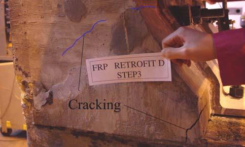


70 E1 F1 E2 F2 E3 F3 E4 Figure 82: Failure progression F4 Page 68

 for specimen F, comparing 135.3 kip-in for specimen C and 313.")


71 E Energy Adsorption Figure 82, Continued F5 The energy adsorbed at the ultimate displacement was kip-in (37.7 kj) for specimen E and kip-in (29.5 kj) for specimen F, comparing kip-in for specimen C and kip-in for specimen D. The anchorage system for rehabilitation and new concrete of specimen resulted in the higher energy absorbing capacity (Figure 83) Specimen D Specimen E 250 Energy [kips-in] Specimen F 50 Specimen C Horizontal Deformation [in] Phase 3 Conclusions Figure 83: Energy due to response In phase 3, the tested specimens C and D were repaired and re-evaluated using and external bracket. In the first case the parapet was completely removed and re-cast (specimen E). In the Page 69
72 second specimen the damaged portion of the parapet was repaired with high strength grout and strengthened with a external bracket. These subassemblies were loaded laterally to failure under displacement control. The results of this phase can be summarized in the following points: The designed steel rehabilitation bracket resists parapet impact loads by yielding of the vertical leg and fracture of the tensile anchor. The external bracket provides a robust repair method for damaged parapets on FRP slabs or other systems where the deck anchorage reinforcement cannot be easily repaired. The use of a newly cast parapet and bracket compares well with the original strength but with improved displacement capability. Repairing a damaged parapet with high strength grout and an external bracket will result in a less effective repair (than complete replacement) but still provides a system that greatly exceeds the design strength. Economical advantages may outweigh the marginal loss in strength that is achieved from this repair. Proper bearing of anchorages on the vertical webs are important for Honeycomb FRP slabs. Failure to do this will result in local flexural damage to the compression flange. Page 70
73 11. PARAPET ACCEPTANCE NCHRP Report 350 details the recommended procedures for the safety performance evaluation of highway features [Ross 1993]. According to this report, acceptable performance consists of the ability to redirect the vehicle; the vehicle should not penetrate, underride, or override the installation although controlled lateral deflection of the test article (parapet) is acceptable. The test article should readily activate in a predictable manner by breaking away, fracturing, or yielding. NCHRP 350 includes a variety of structural elements within the definition of test article, including impact barriers and sign structures. While some test articles produce the safest behavior by breaking away or fracturing, bridge parapets do not. The bridge parapet should be prevented from break away or fracture. This mode of failure in a bridge system could result in a vehicle or parapet falling off a bridge and impacting traffic or people below. The structural function of the bridge parapet is to redirect the vehicle impact. Safety is provided by containing the vehicle on the bridge system and preventing it from movement into adjacent lanes. Energy adsorption is not considered to be one of the design characteristics of the reinforced concrete system and is typically accounted for in the crash resistance of vehicles. Consequently, the design of the parapet is based on achieving a force limit. AASHTO LRFD Bridge Design Specifications 1998 allow for use of a yield line mechanism in achieving the force limit. The yield line mechanism can form within the parapet if adequate longitudinal length is provided. For short longitudinal lengths the parapet is allowed to form a yield line at the interface between the parapet and deck. Both cases require that yield does not enter into the deck. For safest behavior: The parapet should have a predictable yield mechanism. The parapet should redirect the vehicle while preventing override The parapet should not exhibit a brittle fracture mechanism Damage should not occur in the supporting deck. The nominal flexural capacity of the parapet can be computed using the standard assumptions for a doubly reinforced concrete beam (ACI 318); these values are in Table 14. The predicted nominal strengths correspond well with the occurrence of global yield of the parapet (Figure 84). In all cases the nominal capacity is much higher than the TL-2 27 kip lateral load level. Less than 1-degree of parapet rotation occurs at the design load level (Figure 84). This magnitude of rotation is on the order of construction errors. Consequently, the parapet should safely redirect a vehicle on impact. Table 14: Nominal capacity A B C D E F Nominal flexural capacity Lateral load at nominal Measured ultimate capacity The parapet connection details used in the existing Dubois Creek Bridge produce damage to the supporting slab (Specimens A and B). Use of headed embedded reinforcement bars allow for the Page 71
74 development of the full strength of the parapet without damage to the supporting slab (Specimens C and D). As a means of retrofitting these systems an exterior plate can be bolted to the deck using all-thread bars (Specimen F). The details of specimen C, D, and F are recommended for future applications Load [kips] Deck A Deck B Deck C Deck E Deck F ACI Nominal Capacity Rotation [degree] Figure 84: Parapet rotation Page 72
75 12. CONCLUSIONS Investigations of reinforced concrete parapet-to-frp slab connections were carried out to examine the behavior and to identify any shortcomings that the system may exhibit when subjected to lateral impact loads. Strengthening techniques and rehabilitation methods were developed to improve the performance of the connection and to provide a means of repair after impact. These goals were achieved through six full-scale experiments (A through F) of the reinforced concrete parapet-to-frp slab connection. Specimens A and B represented the details used in a demonstration bridge project in Pennsylvania. Specimens C and D represents improved connection methods, while E an F represent rehabilitation methods. Specimen A failed due to brittle fracture of the top layer of FRP slab at the location of the tensile steel reinforcement. The fracture of top layer of FRP slab resulted from fabrication defects of the FRP slab. Specimen B failed due to abrupt pullout of the tensile reinforcement embedded in FRP slab. The ultimate load of specimen A and B greatly exceeded the AASHTO TL-2 design load of 27 kips. Prior to the TL-2 level, gap opening between the parapet and FRP slab on both specimen A and B, and cracking of the external web on specimen A was observed. No buckling of the FRP slab was observed. The experimental performance of specimen A and B indicates that the current design of reinforced concrete parapet-frp slab connection may be adequate for the TL-2 design load level. However, the observed failure mechanisms of specimen A and B are not desirable and may result in abruptly loss of the parapet. Additional skins of FRP sheeting were added to top layer of FRP slab for both specimen C and D to avoid the fracture of FRP slab occurring in specimen A. Improved anchorage of reinforcement embedded in FRP slab to inhibit abrupt pullout occurring in specimen B. Both specimen C and D achieved full development of the reinforcement in the concrete parapet. The behaviors of specimen C and D were more ductile than those of specimen A and B. Specimen D had higher ultimate load capacity than specimen A and B due to the improved anchorage system. Although a smaller size of steel reinforcement was used in specimen C (#5), the ultimate load of specimen C almost equaled that of specimen B. Neither crack of external web or buckling of the FRP slab was observed. The failure mechanisms of specimen C and D provide greater margin of safety against failure than specimen A and B, and have an advantage for potential rehabilitation after impact. A rehabilitation system was developed for damaged concrete parapet and FRP slab-concrete parapet connection. Specimen E and F were rehabilitated from damaged specimen C and D, respectively. In specimen E the damaged parapet was removed and new compression reinforcement transverse reinforcement was installed. A new parapet was cast and brackets were installed. In specimen F the damaged portion of concrete in the vicinity of the tensile parapet reinforcement was removed. The tensile reinforcement was cut, the section was grouted, and the bracket was installed. Specimen E failed due to the bearing failure of base plate (½ inch thickness A36 steel) followed by fracture of the threaded rod connecting the bracket to the FRP slab. To avoid bearing failure, 1 ½ inch thickness A375 steel was used for base plate. Specimen F failed due to the fracture of threaded rod. Both specimen E and F were more ductile than specimen C and D, and had lower ultimate load capacity than specimen C and D. However the ultimate load capacities of both specimens were much higher than the TL-2 design load level. Although the compressive reinforcement of specimen E is smaller than that of specimen F, the newly cast concrete of parapet of specimen E produced a higher load capacity than specimen F. Page 73
76 Through the research program the following conclusions can are made: Fabrication techniques of the FRP play a vital role in the strength of the system. Poor fabrication (specimen A) led to brittle fracture of the slab at 20% of the expected capacity. Non-destructive evaluation of the material should be conducted prior to service to ensure system integrity. When properly fabricated, the cellular construction used by Hardcore Composites provides a robust slab system. Results show that a properly fabricated slab remains composite up to the ultimate load. The connection details used for the Dubois Creek Bridge provide enough strength to exceed the demands imposed by the AASHTO TL-2 load level. Gap opening between parapet and the slab can be observed prior to the TL-2 load level. Due to the elastic behavior of the system the gap will close on unloading. The ultimate failure of the parapet to slab connection is due to brittle bond loss of the reinforcement embedded in the FRP slab. Current anchorage methods rely on reinforcement-to-resin transfer and passive confinement of the top skin. To prevent a brittle failure in the Dubois Creek Bridge, the anchorage of the reinforcement in the slab should be improved. Existing anchorage details (A and B) do not meet the AASHTO A that reinforcing steel for concrete barriers shall have embedment length sufficient to develop the yield strength. The anchorage improvements used in specimen C and D and the retrofit E and F are shown to meet the requirements. Anchorage of the slab reinforcement using headed bars and bonding wafers results in no bond loss or damage to the slab system. Use of the anchorage methods presented allow for full development of the reinforcement at the interface between the parapet and slab. The improved technique also decreases the translational stiffness between the parapet and slab. Use of #5 reinforcement at 8-in. spacing results in yielding of the tensile reinforcement in the parapet at a load level below the AASHTO TL-2 demand. To resist the TL-2 demands at stress levels within the elastic range, #6 or larger reinforcement at 8-in. spacing should be used to anchor the parapets. The FRP slabs behaved elastically up to the ultimate load capacity of the parapet. The use of an epoxy overlay had negligible effect on the stiffness of the slab. The steel rehabilitation bracket presented resists parapet impact loads by yielding of the vertical leg and fracture of the tensile anchor. The external bracket provides a robust repair method for damaged parapets on FRP slabs or other systems where the deck anchorage reinforcement cannot be easily repaired. The use of a newly cast parapet and bracket compares well with the original strength but with improved displacement capability. Page 74
77 Repairing a damaged parapet with high strength grout and an external bracket will result in a less effective repair (than complete replacement) but still provides a system that greatly exceeds the design strength. Economical advantages may outweigh the marginal loss in strength that is achieved from this repair. Proper bearing of anchorages on the vertical webs are important for Honeycomb FRP slabs. Failure to do this will result in local flexural damage to the compression flange. The improved connection detail and the retrofit details used meet the performance criteria of NCHRP 350 under static loading. Dynamic testing should be conducted to verify the performance of the FRP under real time impact loads. Page 75
78 13. FUTURE WORK While the present research provides a comprehensive study of honeycomb FRP-to-reinforced parapet behavior further examination of a few topics could be investigated to supplement this work. Future research should include: 1) Full size impact load tests on large bridge spans to verify the development of the expected AASHTO parapet yield-line mechanism. This will validate the AASHTO yield-line concept and provide a proof test for longer span FRP applications. 2) Ultimate strength tests on the honeycomb Bridge deck system to investigate the potential application for long span bridges. 3) Further examination of the wearing surface delamination present in the as-built bridge system and the development of a reliable wearing surface application technique. 4) Non-destructive evaluation techniques such as impact-echo methods should be developed for inspection of FRP slab systems to ensure FRP strength prior to installation. Page 76
79 14. REFERENCES ACI , Building Code Requirements for Structural Concrete and Commentary. American Concrete Institute, American Association of State Highway and Transportation Officials, AASHTO LRFD Bridge Design Specifications, Washington, DC, ASTM, Standard Test Method for Compressive Strength of Cylindrical Concrete Specimens: Designation C ASTM Standards, American Society for Testing Materials, Philadelphia, Pennsylvania, Catbas, H., Analysis of Dubois Creek Bridge, Susquehanna County Analysis Report, Revision B, Hardcore Composites, July 2002, pp.11. Ross, H.E., Sicking, D. L., Zimmer, R. A., Michie, J. D., NCHRP Report 350: Recommended Procedures for the Safety Performance Evaluation of Highway Features, Washington D.C.: National Academy Press, Roark, R., and Young, W., C., Roark's formulas for stress and strain, 6th ed., New York: McGraw-Hill, 1989, pp.763. Page 77

80 15. APPENDIX 1 CONCRETE MIX DESIGN Page 78
Erector Connector Meadow Burke Company In- Plane Performance
 Lehigh University Lehigh Preserve ATLSS Reports Civil and Environmental Engineering 1-1-2007 Erector Connector Meadow Burke Company In- Plane Performance Clay Naito Follow this and additional works at:
ABC-UTC. Research Progress Report (Feasibility Study) Title: Alternative ABC Connections Utilizing UHPC. March, 2017
 Title: Alternative ABC Connections Utilizing UHPC. March, 2017") ABC-UTC Research Progress Report (Feasibility Study) Title: Alternative ABC Connections Utilizing UHPC ABSTRACT March, 2017 Accelerated Bridge Construction (ABC) is a method of bridge construction designed
ABC-UTC Research Progress Report (Feasibility Study) Title: Alternative ABC Connections Utilizing UHPC ABSTRACT March, 2017 Accelerated Bridge Construction (ABC) is a method of bridge construction designed
FLEXURAL AND SHEAR STRENGTHENING OF REINFORCED CONCRETE STRUCTURES WITH NEAR SURFACE MOUNTED FRP RODS
 FLEXURAL AND SHEAR STRENGTHENING OF REINFORCED CONCRETE STRUCTURES WITH NEAR SURFACE MOUNTED FRP RODS ABSTRACT The use of Near Surface Mounted (NSM) Fiber Reinforced Polymer (FRP) rods is a new and promising
MECHANICAL CHARACTERIZATION OF SANDWICH STRUCTURE COMPRISED OF GLASS FIBER REINFORCED CORE: PART 1
 Composites in Construction 2005 Third International Conference Lyon, France, July 11 13, 2005 MECHANICAL CHARACTERIZATION OF SANDWICH STRCTRE COMPRISED OF GLASS FIBER REINFORCED CORE: PART 1 S.V. Rocca
In-Plane and Out-of-Plane Performance of the MINI-MC Flange Connector
 Lehigh University Lehigh Preserve ATLSS Reports Civil and Environmental Engineering 7-1-2009 In-Plane and Out-of-Plane Performance of the MINI-MC Flange Connector Clay Naito Ruirui Ren Follow this and
BEHAVIOR OF INFILL MASONRY WALLS STRENGTHENED WITH FRP MATERIALS
 BEHAVIOR OF INFILL MASONRY WALLS STRENGTHENED WITH FRP MATERIALS D.S. Lunn 1,2, V. Hariharan 1, G. Lucier 1, S.H. Rizkalla 1, and Z. Smith 3 1 North Carolina State University, Constructed Facilities Laboratory,
SHEAR AND BUCKLING STRENGTHENING OF STEEL BRIDGE GIRDER USING SMALL-DIAMETER CFRP STRANDS
 20 th International Conference on Composite Materials Copenhagen, 19-24 th July 2015 SHEAR AND BUCKLING STRENGTHENING OF STEEL BRIDGE GIRDER USING SMALL-DIAMETER CFRP STRANDS Hamid Kazem 1, Sami Rizkalla
SEISMIC REHABILITATION OF REINFORCED CONCRETE BRIDGE COLUMNS IN MODERATE EARTHQUAKE REGIONS USING FRP COMPOSITES
 13 th World Conference on Earthquake Engineering Vancouver, B.C., Canada August 1-6, 24 Paper No. 58 SEISMIC REHABILITATION OF REINFORCED CONCRETE BRIDGE COLUMNS IN MODERATE EARTHQUAKE REGIONS USING FRP
Failure Mechanism for Large-Sized Grouted Anchor Bolt under Tensile Load
 Failure Mechanism for Large-Sized Grouted Anchor Bolt under Tensile Load Nam-Ho Lee 1), Il-Hwan Moon 1), and In-Soo Ju 1) 1) Department of Civil/Architectural Engineering, Korea Power Engineering Company,
Field and Laboratory Performance of FRP Bridge Panels
 Field and Laboratory Performance of FRP Bridge s D. Stone, A. Nanni, & J. Myers University of Missouri Rolla, Rolla, Missouri, USA ABSTRACT: The objective of this research project is to examine the use
Chapter 2 Notation and Terminology
 Reorganized 318 Chapter Titles Chapter 1 General 1.1 Scope 1.2 Purpose 1.3 Interpretation 1.4 Drawings and Specifications 1.5 Testing and Inspection 1.6 Administatration and Enforcement 1.6.1 Retention
INFLUENCE OF PRSTRESS LEVEL ON SHEAR BEHAVIOR OF SEGMENTAL CONCRETE BEAMS WITH EXTERNAL TENDONS
 - Technical Paper - INFLUENCE OF PRSTRESS LEVEL ON SHEAR BEHAVIOR OF SEGMENTAL CONCRETE BEAMS WITH EXTERNAL TENDONS Dinh Hung NGUYEN *1, Ken WATANABE *2, Junichiro NIWA *3 and Tsuyoshi HASEGAWA *4 ABSTRACT
Field Instrumentation and Long-Term Monitoring of the FRP Bridge over Dubois Creek in Great Bend, PA
 Lehigh University Lehigh Preserve ATLSS Reports Civil and Environmental Engineering 11-1-2003 Field Instrumentation and Long-Term Monitoring of the FRP Bridge over Dubois Creek in Great Bend, PA Ian C.
How Loads Are Distributed
 LOAD DISTRIBUTION 1 LOAD DISTRIBUTION This section illustrate how load will transmit from the deck to the stringers. Determining the fraction of load carried by a loaded member and the remainder distributed
FRP Anchorage Systems for Infill Masonry Structures
 FRP Anchorage Systems for Infill Masonry Structures Dillon S. Lunn Graduate Research Assistant, Department of Civil, Construction, and Environmental Engineering, North Carolina State University, Raleigh,
Load capacity rating of an existing curved steel box girder bridge through field test
 109 Dongzhou Huang Senior Engineer IV TS Transportation Design South Florida Atkins North America Load capacity rating of an existing curved steel box girder bridge through field test Abstract This paper
CHAPTER 5 FINITE ELEMENT ANALYSIS OF GFRP COMPOSITE BRIDGE DECK PANELS
 80 CHAPTER 5 FINITE ELEMENT ANALYSIS OF GFRP COMPOSITE BRIDGE DECK PANELS 5.1 GENERAL Bridge decks made of FRP have been widely studied and increasingly used in highway bridges, both in new construction
APPENDIX B. LOAD FRAME. This Appendix will describe the philosophy in the design and operation of the loading system.
 APPENDIX B. LOAD FRAME This Appendix will describe the philosophy in the design and operation of the loading system. LOAD FRAME The large-scale gusset plate testing required a unique loading fixture. A
Seismic Behaviour of RC Shear Walls
 Ductile Detailing of RC Structures :: IS:13920-1993 1993 Short Course on Seismic Design of RC Structures Durgesh C. Rai Department of Civil Engineering, IIT Kanpur The material contained in this lecture
BEHAVIOR OF FULL-SCALE SHEAR DEFICIENT CORNER RC BEAM-COLUMN CONNECTIONS RETROFITTED WITH CFRP SHEETS
 BEHAVIOR OF FULL-SCALE SHEAR DEFICIENT CORNER RC BEAM-COLUMN CONNECTIONS RETROFITTED WITH CFRP SHEETS Y.A. Al-Salloum, S.H. Alsayed, T.H. Almusallam and N.A. Siddiqui DEPARTMENT OF CIVIL ENGINEERING PO
Appendix D.2. Redundancy Analysis of Prestressed Box Girder Superstructures under Vertical Loads
 Appendix D.2 Redundancy Analysis of Prestressed Box Girder Superstructures under Vertical Loads By Jian Yang, Giorgio Anitori, Feng Miao and Michel Ghosn Contents 1. Introduction...1 2. Prestressed Concrete
PRESTRESSED CONCRETE STRUCTURES. Amlan K. Sengupta, PhD PE Department of Civil Engineering Indian Institute of Technology Madras
 PRESTRESSED CONCRETE STRUCTURES Amlan K. Sengupta, PhD PE Department of Civil Engineering Indian Institute of Technology Madras Module 5: Analysis and Design for Shear and Torsion Lecture-23: Analysis
Testing and Evaluation of CFS L-headers
 Missouri University of Science and Technology Scholars' Mine International Specialty Conference on Cold- Formed Steel Structures (2008) - 19th International Specialty Conference on Cold-Formed Steel Structures
INTERNATIONAL JOURNAL OF CIVIL AND STRUCTURAL ENGINEERING Volume 2, No 2, 2011
 INTERNATIONAL JOURNAL OF CIVIL AND STRUCTURAL ENGINEERING Volume 2, No 2, 2011 Copyright 2010 All rights reserved Integrated Publishing services Research article ISSN 0976 4399 Nonlinear Seismic Behavior
Strengthening Highway Bridges with CFRP Composites
 Strengthening Highway Bridges with CFRP Composites By Tarek Alkhrdaji The future growth of nations and their economical prosperity are closely related to the potency of their transportation infrastructures.
Basic types of bridge decks
 Bridge Deck Slab 1 Introduction 2 Bridge deck provide the riding surface for traffic, support & transfer live loads to the main load carrying member such as girder on a bridge superstructure. Selection
SHEAR PERFORMANCE OF RC MEMBERS STRENGTHENED WITH EXTERNALLY BONDED FRP WRAPS
 Proc., 12th World Conference on Earthquake Engineering, Jan 3- Feb 4, 2, Auckland, New Zealand, paper 35,1 pp SHEAR PERFORMANCE OF RC MEMBERS STRENGTHENED WITH EXTERNALLY BONDED FRP WRAPS AHMED KHALIFA,
Elimination of Deck Joints Using a Corrosion Resistant FRP Approach
 Elimination of Deck Joints Using a Corrosion Resistant FRP Approach Louisiana Transportation Conference February 2009 Aziz Saber, Ph.D., P.E. Chair of Civil Engineering Louisiana Tech University LTRC LA
BEHAVIOR OF FRP SANDWICH PANELS FOR TRANSPORTATION INFRASTRUCTURE
 IV ACMBS MCAPC 4 th International Conference on Advanced Composite Materials in Bridges and Structures 4 ième Conférence Internationale sur les matériaux composites d avant-garde pour ponts et charpentes
Deflection Assessment of an FRP-Reinforced Concrete Bridge. By Danielle K. Stone, Andrea Prota, and Antonio Nanni
 Deflection Assessment of an FRP-Reinforced Concrete Bridge By Danielle K. Stone, Andrea Prota, and Antonio Nanni Synopsis: Serviceability of FRP-reinforced concrete structures remains a highly relevant
STRENGTHENING OF INFILL MASONRY WALLS USING BONDO GRIDS WITH POLYUREA
 I.1 June 2005 STRENGTHENING OF INFILL MASONRY WALLS USING BONDO GRIDS WITH POLYUREA SUMMARY Glass fiber reinforced polymer (GFRP) grids reinforced polyurea was used to strengthen unreinforced concrete
CHAPTER III DYNAMIC BEHAVIOR OF A LABORATORY SPECIMEN
 CHAPTER III DYNAMIC BEHAVIOR OF A LABORATORY SPECIMEN To address the vibration response of a long span deck floor system, an experiment using a specimen that resembles the conditions found in the in-situ
PRE-CONSTRUCTION INVESTIGATION FOR THE REHABILITATION OF A BRIDGE USING INTERNAL FRP TECHNOLOGIES
 IV ACMBS MCAPC ADVANCED COMPOSITE MATERIALS IN BRIDGES AND STRUCTURES MATÉRIAUX COMPOSITES D AVANT-GARDE POUR PONTS ET CHARPENTES Calgary, Alberta, July 20 23, 2004 / 20 23 juillet 2004 PRE-CONSTRUCTION
Vierendeel Steel Truss / Composite Skin Hull Test
 Final Report Project I, ONR Grant No. N00014-01-1-0956 Non-magnetic Stainless Steel for Double Hull Ship Construction by Joachim L. Grenestedt, Ph.D. jog5@lehigh.edu Richard Sause, Ph.D. rs0c@lehigh.edu
Evaluation of the Orientation of 90 and 180 Reinforcing Bar Hooks in Wide Members
 Research Note Research Note RN-2009-2 Evaluation of the Orientation of 90 and 180 Reinforcing Bar Hooks in Wide Members Introduction Longitudinal reinforcing steel bars in flexural members are often developed
Appendix M 2010 AASHTO Bridge Committee Agenda Item
 Appendix M 2010 AASHTO Bridge Committee Agenda Item 2010 AASHTO BRIDGE COMMITTEE AGENDA ITEM: SUBJECT: LRFD Bridge Design Specifications: Section 5, High-Strength Steel Reinforcement TECHNICAL COMMITTEE:
Finite Element Analysis of RC Beams Strengthened with FRP Sheets under Bending
 Australian Journal of Basic and Applied Sciences, 4(5): 773-778, 2010 ISSN 1991-8178 Finite Element Analysis of RC Beams Strengthened with FRP Sheets under Bending 1 2 Reza Mahjoub, Seyed Hamid Hashemi
RESILIENT INFRASTRUCTURE June 1 4, 2016
 RESILIENT INFRASTRUCTURE June 1 4, 2016 MOMENT REDISTRIBUTION OF GFRP-RC CONTINUOUS T-BEAMS S. M. Hasanur Rahman M.Sc. Student, University of Manitoba, Canada Ehab El-Salakawy Professor and CRC in Durability
Flexural Behavior of RC T- Section Beams Strengthened with Different Configurations of CFRP Laminates
 Research Article International Journal of Current Engineering and Technology ISSN 2277-4106 2012 INPRESSCO. All Rights Reserved. Available at http://inpressco.com/category/ijcet Flexural Behavior of RC
FINITE ELEMENT ANALYSIS OF REINFORCED CONCRETE BRIDGE PIER COLUMNS SUBJECTED TO SEISMIS LOADING
 FINITE ELEMENT ANALYSIS OF REINFORCED CONCRETE BRIDGE PIER COLUMNS SUBJECTED TO SEISMIS LOADING By Benjamin M. Schlick University of Massachusetts Amherst Department of Civil and Environmental Engineering
THE ANALYTICAL STUDY OF STRENGTHENING THE HORIZONTALLY CURVED STEEL BEAM WITH CFRP LAMINATES
 THE ANALYTICAL STUDY OF STRENGTHENING THE HORIZONTALLY CURVED STEEL BEAM WITH CFRP LAMINATES Hayder M.K. Al-Mutairee, PhD, Asst. Prof. Ali I. AbdulAbbas, B.Sc., M.Sc. Student Department of Civil Engineering,
EXPERIMENTAL RESULTS
 Chapter 4 EXPERIMENTAL RESULTS 4.1 Introduction This chapter presents the results from the half scale interior Corcon rib beam-column subassemblage and the FRP repaired subassemblage. As described in chapter
EXPERIMENTAL INVESTIGATION ON THE INTERACTION OF REINFORCED CONCRETE FRAMES WITH PRECAST-PRESTRESSED CONCRETE FLOOR SYSTEMS
 EXPERIMENTAL INVESTIGATION ON THE INTERACTION OF REINFORCED CONCRETE FRAMES WITH PRECAST-PRESTRESSED CONCRETE FLOOR SYSTEMS B.H.H. Peng 1, R.P. Dhakal 2, R.C. Fenwick 3, A.J. Carr 4 and D.K. Bull 5 1 PhD
INNOVATIVE HYBRID WEARING SURFACES FOR FRP BRIDGE DECKS
 16 TH INTERNATIONAL CONFERENCE ON COMPOSITE MATERIALS INNOVATIVE HYBRID WEARING SURFACES FOR FRP BRIDGE DECKS Riyad S. Aboutaha Syracuse University Keywords: FRP decks, bridge decks, wearing surfaces Abstract
AFRP retrofitting of RC structures in Japan
 AFRP retrofitting of RC structures in Japan H. Shinozaki Civil Engineering R&D Department, Sumitomo Mitsui Construction Corporation, Japan G.R. Pandey School of Engineering, James Cook University, Australia
Appendix D.1. Redundancy Analysis of Composite Spread Box Girder Superstructures under Vertical Loads
 Appendix D.1 Redundancy Analysis of Composite Spread Box Girder Superstructures under Vertical Loads By Jian Yang, Feng Miao and Michel Ghosn Contents 1. Introduction...1 2. Structural Modeling...3 2.1
CHAPTER 4 STRENGTH AND STIFFNESS PREDICTIONS OF COMPOSITE SLABS BY FINITE ELEMENT MODEL
 CHAPTER 4 STRENGTH AND STIFFNESS PREDICTIONS OF COMPOSITE SLABS BY FINITE ELEMENT MODEL 4.1. General Successful use of the finite element method in many studies involving complex structures or interactions
Bijan Khaleghi, Ph, D. P.E., S.E.
 0 Submission date: July, 0 Word count: 0 Author Name: Bijan Khaleghi Affiliations: Washington State D.O.T. Address: Linderson Way SW, Tumwater WA 0 INTEGRAL BENT CAP FOR CONTINUOUS PRECAST PRESTRESSED
Modelling of RC moment resisting frames with precast-prestressed flooring system
 Modelling of RC moment resisting frames with precast-prestressed flooring system B.H.H. Peng, R.P. Dhakal, R.C. Fenwick & A.J. Carr Department of Civil Engineering, University of Canterbury, Christchurch.
VOL I: Bridge Design & Load Rating
 PRESERVATION OF MISSOURI TRANSPORTATION INFRASTRUCTURES VOL I: Bridge Design & Load Rating VALIDATION OF FRP COMPOSITE TECHNOLOGY THROUGH FIELD TESTING Strengthening of Bridge X-495 Iron County, MO Prepared
Flexural Behavior of RC T- Section Beams Strengthened with Different Configurations of CFRP Laminates
 I NPRESSCO NTERNATIONAL PRESS CORPORATION Research Article International Journal of Current Engineering and Technology ISSN 2277-4106 2012 INPRESSCO. All Rights Reserved. Available at http://inpressco.com/category/ijcet
Nonlinear Models of Reinforced and Post-tensioned Concrete Beams
 111 Nonlinear Models of Reinforced and Post-tensioned Concrete Beams ABSTRACT P. Fanning Lecturer, Department of Civil Engineering, University College Dublin Earlsfort Terrace, Dublin 2, Ireland. Email:
Strengthening of RC Beams subjected to Combined Torsion and Bending with GFRP Composites
 Available online at www.sciencedirect.com Procedia Engineering 51 ( 2013 ) 282 289 Chemical, Civil and Mechanical Engineering Tracks of 3 rd Nirma University International Conference on Engineering (NUiCONE
Effect of prestressed CFRP plate location on behavior of RC beam strengthened with prestressed CFRP plate
 Effect of prestressed CFRP plate location on behavior of RC beam strengthened with prestressed CFRP plate Majid Mohammed Ali Kadhim Ass. Lecturer Babylon University Mohammed Jassam Mohammed Ass. Lecturer
The Use of Sustainable Materials for Quick Repair of Aging Bridges
 The Use of Sustainable Materials for Quick Repair of Aging Bridges Phase II Final Report PI: Azadeh Parvin, D.Sc. Associate Professor Department of Civil Engineering College of Engineering Prepared for
PHASE 1 SUMMARY REPORT
 PCI / NSF Project Development of a Seismic Design Methodology for Precast Diaphragms PHASE 1 SUMMARY REPORT By Clay Naito, Ph.D., P.E. - Principal Investigator Wesley Peter - Graduate Student Researcher
M. Bruneau 1, Y. Alzeni 2, P. Fouché 2
 Steel Innovations Conference 2013 Christchurch, New Zealand 21-22 February 2013 SEISMIC BEHAVIOR OF CONCRETE-FILLED STEEL SANDWICH WALLS AND CONCRETE-FILLED STEEL TUBE COLUMNS M. Bruneau 1, Y. Alzeni 2,
Development of a Seismic Design Methodology for Precast Diaphragms - PHASE 1 SUMMARY REPORT
 Lehigh University Lehigh Preserve ATLSS Reports Civil and Environmental Engineering 1-1-26 Development of a Seismic Design Methodology for Precast Diaphragms - PHASE 1 SUMMARY REPORT Clay Naito Wesley
High Performance Steel Girders with Tubular Flanges
 Lehigh University Lehigh Preserve ATLSS Reports Civil and Environmental Engineering 6-1-25 High Performance Steel Girders with Tubular Flanges Bong-Gyun Kim Richard Sause Follow this and additional works
Ultimate strength prediction for reinforced concrete slabs externally strengthened by fiber reinforced polymer (FRP)
") Ultimate strength prediction for reinforced concrete slabs externally strengthened by fiber reinforced polymer (FRP) Abstract This paper presents the potential use of externally bonded fiber reinforced
Ultimate strength prediction for reinforced concrete slabs externally strengthened by fiber reinforced polymer (FRP) Abstract This paper presents the potential use of externally bonded fiber reinforced
Structural Performance of 8-inch NRG Concrete Masonry Units. Report Compiled for: Niagara Regional Group. Date: January 28, 2013
 Structural Performance of 8-inch NRG Concrete Masonry Units Report Compiled for: Niagara Regional Group Date: January 28, 2013 Report Prepared by: Dr. Shawn Gross, Associate Professor Dr. David Dinehart,
Flexural Behaviour of Composite Girders Using FRP and Precast Ultra-High-Strength Fiber-Reinforced Concrete Slabs
 Flexural Behaviour of Composite Girders Using FRP and Precast Ultra-High-Strength Fiber-Reinforced Concrete Slabs S.V.T. Janaka Perera 1*, Hiroshi Mutsuyoshi 1 and Nguyen Duc Hai 2 1 Saitama University,
Nonlinear Redundancy Analysis of Truss Bridges
 Nonlinear Redundancy Analysis of Truss Bridges Analysis Report Dr. Michel Ghosn Ph.D. Graziano Fiorillo The City College of New York / CUNY SEPTEMBER 2013 Acknowledgments This section describes the redundancy
BUCKLING ANALYSIS OF PULTRUDED GFRP HOLLOW BOX BEAM
 BUCKLING ANALYSIS OF PULTRUDED GFRP HOLLOW BOX BEAM Donna CHEN Ph.D. Candidate University of Calgary, Department of Civil Engineering 2500 University Drive NW, Calgary, Alberta, T2N 1N4, Canada dsmchen@ucalgary.ca
NEW COMPOSITE CONSTRUCTION OF HYBRID BEAMS COMBINING STEEL INVERTED T-SECTION AND RC FLANGE
 NEW COMPOSITE CONSTRUCTION OF HYBRID BEAMS COMBINING STEEL INVERTED T-SECTION AND RC FLANGE Alex Remennikov 1, Marcus Roche 2 ABSTRACT: Steel and concrete composite beams are typically formed by shear
Structural Behavior of Timber Aluminum Composite Beams Under Impact Loads. Samoel M. Saleh, Nabeel A. Jasim
 86 International Journal of Scientific & Engineering Research, Volume, Issue 0, October 04 ISSN 9 8 Structural Behavior of Timber Aluminum Composite Beams Under Impact Loads Samoel M. Saleh, Nabeel A.
Failure Analysis of the US 422 Girder Fracture
 Lehigh University Lehigh Preserve ATLSS Reports Civil and Environmental Engineering 10-1-2004 Failure Analysis of the US 422 Girder Fracture Eric J. Kaufmann Robert J. Connor John W. Fisher Follow this
EXPERIMENTAL STUDY ON DOUBLE LAP JOINTS COMPOSED OF HYBRID CFRP/GFRP LAMINATE
 EXPERIMENTAL STUDY ON DOUBLE LAP JOINTS COMPOSED OF HYBRID CFRP/GFRP LAMINATE Hiroshi MUTSUYOSHI 1) and Nguyen Duc HAI 1) 1) Structural Material Lab., Department of Civil and Environmental Engineering,
Upgrading the shear strength of non-ductile reinforced concrete frame connections using FRP overlay systems
 Upgrading the shear strength of non-ductile reinforced concrete frame connections using FRP overlay systems Mohamad J. Terro Associate Professor. Civil Engineering Department, Kuwait University. Sameer
Enhancing the Compressive Strength of Square Cross Sectional Column Using FRP Material
 Enhancing the Compressive Strength of Square Cross Sectional Column Using FRP Material Satyam Tiwari 1, Satyendra Dubey 2, Y.K Bajpai 3 1 M.Tech Student, Department of Civil Engineering, G.G.I.T.S Jabalpur,
FIBRE COMPOSITES PILE REHABILITATION AND CONCRETE FORMWORK JACKET CONCEPT DEVELOPMENT AND FINITE ELEMENT ANALYSIS
 Fourth Asia-Pacific Conference on FRP in Structures (APFIS 2013) 11-13 December 2013, Melbourne, Australia 2013 International Institute for FRP in Construction FIBRE COMPOSITES PILE REHABILITATION AND
In-plane testing of precast concrete wall panels with grouted sleeve
 In-plane testing of precast concrete wall panels with grouted sleeve P. Seifi, R.S. Henry & J.M. Ingham Department of Civil Engineering, University of Auckland, Auckland. 2017 NZSEE Conference ABSTRACT:
Appendix A Proposed LRFD Specifications and Commentary
 NCHRP Project 12-71 Design Specifications and Commentary for Horizontally Curved Concrete Box-Girder Highway Bridges Appendix A Proposed LRFD Specifications and Commentary A-1 A-2 4.2 DEFINITIONS (Additional)
Modjeski and Masters, Inc. Consulting Engineers 04/18/06 St. Croix River Bridge 3D Analysis Report Introduction
 Introduction This memo presents a summary of a three dimensional (3D) analysis of the Organic concept for the proposed St. Croix River bridge project. The Organic concept has several attributes that are
FINAL REPORT EFFECT OF GIRDER SPACING ON BRIDGE DECK RESPONSE. James G. Buckler Graduate Research Assistant
 FINAL REPORT EFFECT OF GIRDER SPACING ON BRIDGE DECK RESPONSE James G. Buckler Graduate Research Assistant Furman W. Barton Faculty Research Scientist Jose P. Gomez Senior Research Scientist Peter J. Massarelli
FRP STRENGTHENING OF 60 YEAR OLD PRE-STRESSED CONCRETE BRIDGE DECK UNITS
 FRP STRENGTHENING OF 60 YEAR OLD PRE-STRESSED CONCRETE BRIDGE DECK UNITS Ryan Cork, Jack Foote, Leo de Waal, Van Thuan Nguyen, Dilum Fernando School of Civil Engineering, The University of Queensland,
Ductile FRP Strengthening Systems
 Ductile FRP Strengthening Systems Hybridization allows strengthening of reinforced concrete beams without drawbacks typical of fiber-reinforced polymer systems BY NABIL F. GRACE, WAEL F. RAGHEB, AND GEORGE
Nonlinear Finite Element Modeling & Simulation
 Full-Scale Structural and Nonstructural Building System Performance during Earthquakes & Post-Earthquake Fire A Joint Venture between Academe, Industry and Government Nonlinear Finite Element Modeling
SEISMIC STRENGTHENING AND REPAIR OF REINFORCED CONCRETE SHEAR WALLS
 SEISMIC STRENGTHENING AND REPAIR OF REINFORCED CONCRETE SHEAR WALLS Josh LOMBARD 1, David T LAU 2, Jag L HUMAR 3, Simon FOO 4 And M S CHEUNG 5 SUMMARY This paper presents the results obtained in a feasibility
Function-integrated GFRP sandwich roof structure Experimental validation of design
 Fourth International Conference on FRP Composites in Civil Engineering (CICE2008) 22-24July 2008, Zurich, Switzerland Function-integrated GFRP sandwich roof structure Experimental validation of design
Purdue e-pubs. Purdue University. Kadir Can Sener Purdue University. Teresa L. Washeleski Michael Baker Jr., Inc,
 Purdue University Purdue e-pubs Indiana Local Technical Assistance Program (LTAP) Technical Reports Indiana Local Technical Assistance Program (LTAP) 10-12-2015 Development of Load Rating Procedures for
DURABILITY PERFORMANCE OF EPOXY INJECTED REINFORCED CONCRETE BEAMS WITH AND WITHOUT FRP FABRICS
 DURABILITY PERFORMANCE OF EPOXY INJECTED REINFORCED CONCRETE BEAMS WITH AND WITHOUT FRP FABRICS Prof. John J. Myers Associate Professor CIES / Department of Civil, Arch., & Env. Engineering University
A Guide for the Interpretation of Structural Design Options for Residential Concrete Structures
 CFA Technical Note: 008-2010 A Guide for the Interpretation of Structural Design Options for Residential Concrete Structures CFA Technical This CFA Technical Note is intended to serve as a guide to assist
Introduction. Crossarm Design
 SUBJECT BCTC 287kV H-Frame Crossarm Finite Element Analysis Report AUTHOR Jeremy Mostoller DATE August 4, 2008 Introduction This report details the analysis and optimization of the glass fiber reinforced
BEHAVIOR OF REINFORCED CONCRETE BEAM WITH OPENING
 International Journal of Civil Engineering and Technology (IJCIET) Volume 8, Issue 7, July 2017, pp. 581 593, Article ID: IJCIET_08_07_062 Available online at http:// http://www.iaeme.com/ijciet/issues.asp?jtype=ijciet&vtype=8&itype=7
Strengthening of an Impact-Damaged PC Girder
 Strengthening of an Impact- PC Girder By Antonio Nanni, PhD, PE R epair of impacted prestressed and reinforced concrete (PC and RC, respectively) structures using traditional and emerging technologies
beni-suef university journal of basic and applied sciences 5 (2016) Available online at ScienceDirect
 Available online at ScienceDirect") beni-suef university journal of basic and applied sciences 5 (2016) 31 44 HOSTED BY Available online at www.sciencedirect.com ScienceDirect journal homepage: www.elsevier.com/locate/bjbas Full Length Article
beni-suef university journal of basic and applied sciences 5 (2016) 31 44 HOSTED BY Available online at www.sciencedirect.com ScienceDirect journal homepage: www.elsevier.com/locate/bjbas Full Length Article
Investigation of Negative Moment Reinforcing in Bridge Decks
 Tech Transfer Summaries Institute for Transportation 9-2015 Investigation of Negative Moment Reinforcing in Bridge Decks Brent Phares Institute for Transportation, bphares@iastate.edu Sameera Jayathilaka
Proposed Modifications to the LRFD Design of U-Beam Bearings
 Proposed Modifications to the LRFD Design of U-Beam Bearings Charles D. Newhouse, Scott A. Bole, W. R. Burkett, Phillip T. Nash, Mostafa El-Shami Performed in Cooperation with the Texas Department of Transportation
INNOVATIVE FIBRE REINFORCED BRIDGE DECK MODULES ABSTRACT
 INNOVATIVE FIBRE REINFORCED BRIDGE DECK MODULES Heather Crocker, ISIS Canada, Winnipeg, MB Emile Shehata, Wardrop Engineering Inc., Winnipeg, MB Rick Haldane-Wilsone, Wardrop Engineering Inc., Winnipeg,
EGCE 406: Bridge Design
 EGCE 406: Bridge Design Design of Slab for Praveen Chompreda Mahidol University First Semester, 2006 Bridge Superstructure Outline Components of bridge Superstructure Types Materials Design of RC Deck
CFRP STRENGTHENING OF CONCRETE BRIDGES WITH CURVED SOFFITS
 CFRP STRENGTHENING OF CONCRETE BRIDGES WITH CURVED SOFFITS Nagaraj Eshwar Dr Tim Ibell Dr Antonio Nanni Graduate Research Assistant Senior Lecturer Jones Professor CIES, # 223 ERL University of Bath CIES,
STEEL REACTION FRAME
 STEEL REACTION FRAME Kyle Coleman, CEE Laboratory Manager Andrew Myers, Assistant Professor Jerome F. Hajjar, Professor and Chair, Director, STReSS Laboratory Department of Civil and Environmental Engineering,
Appendix B Flexural Resistance of Members with Reinforcing Bars Lacking Well-Defined Yield Plateau
 Appendix B Flexural Resistance of Members with Reinforcing Bars Lacking Well-Defined Yield Plateau B.1 Introduction The nominal moment capacity (M n ) for non-prestressed members is commonly calculated
STRENGTHENING OF MASONRY WITH NEAR SURFACE MOUNTED FRP BARS. Abstract
 STRENGTHENING OF MASONRY WITH NEAR SURFACE MOUNTED FRP BARS J. Gustavo Tumialan, University of Missouri-Rolla, Rolla, MO Nestore Galati, University of Missouri-Rolla, Rolla, MO Sinaph M. Namboorimadathil,
STRENGTHENING OF UNBONDED POST-TENSIONED CONCRETE SLABS USING EXTERNAL FRP COMPOSITES
 STRENGTHENING OF UNBONDED POST-TENSIONED CONCRETE SLABS USING EXTERNAL FRP COMPOSITES F. El M e s k i 1 ; M. Harajli 2 1 PhD student, Dept. of Civil and Environmental Engineering, American Univ. of Beirut;
Site Director: Dr. Sami Rizkalla Associate Director: Dr. Rudi Seracino Date: February 1 st, 2011
 Site Director: Dr. Sami Rizkalla Associate Director: Dr. Rudi Seracino Date: February 1 st, 2011 AltusGroup, Inc. Freyssinet, Inc. Fyfe Company, LLC Grancrete, Inc. Martin Marietta Composites Nippon Steel
1337. Seismic response of beam-column joints rehabilitated with FRP sheets and buckling restrained braces
 1337. Seismic response of beam-column joints rehabilitated with FRP sheets and buckling restrained braces Heecheul Kim 1, Dae-Jin Kim 2, Min Sook Kim 3, Young Hak Lee 4 Kyung Hee University, Yongin, Republic
Introduction to Structural Analysis TYPES OF STRUCTURES LOADS AND
 AND Introduction to Structural Analysis TYPES OF STRUCTURES LOADS INTRODUCTION What is the role of structural analysis in structural engineering projects? Structural engineering is the science and art
Structural Characteristics of New Composite Girder Bridge Using Rolled Steel H-Section
 Proc. Schl. Eng. Tokai Tokai Univ., Univ., Ser. ESer. E 41 (2016) (2016) - 31-37 Structural Characteristics of New Composite Girder Bridge Using Rolled Steel H-Section by Mohammad Hamid ELMY *1 and Shunichi