COMPARATIVE REPORT CYPECAD VS. ETABS
|
|
|
- Ross McLaughlin
- 6 years ago
- Views:
Transcription
1 COMPARATIVE REPORT CYPECAD VS. ETABS
2 Contents SIMPLE FRAME EXAMPLE Introduction Dimensions and applied loads Materials and applied design code Nodes Moment and shear in the beams and columns of the frame Displacement due to lateral loads Dynamic analysis (seismic load) Additional accidental eccentricity Wind Conclusion Sign criteria... 36
3 SIMPLE FRAME EXAMPLE MKS system of units
4 1. Introduction The present report compares some of the aspects which can be observed when calculating the same structure using two different structural analysis software programs. In this case, the software programs to be used are CYPECAD from CYPE Ingenieros, S.A. and ETABS fromcomputers&structures, Inc. For the elaboration of the structural model, the 2013 version of CYPECAD has been used and the version of ETABS. 2. Dimensions and applied loads 2.1. Dimensions For this comparative example, a simple frame with the following dimensions has been chosen: 2.2. Applied loads Figure 1.Frame dimensions [metres] (Source: Autocad) CYPECAD automatically generates the self-weight of the structural elements (beams, columns, etc.) and with a Dead Load of 0.1 tons, these two loads constitute the permanent load loadcase. 4
 ETABSallows users to choose whether or not the self-weight is to be considered by indicating 1 or 0 in the Self-Weight Multiplier,")
5 Figure 2. Dimensions [centimetres] and applied loads [tons] (Source: CYPECAD) ETABSallows users to choose whether or not the self-weight is to be considered by indicating 1 or 0 in the Self-Weight Multiplier, to take into account or not the self-weight of the elements, respectively. Figure 3. Self-Weight Multiplier coefficient (Source: ETABS) Seismic and wind loads are applied in sections 7 and 9, respectively. 3. Materials and applied design code TheMKS system of units (metres, kilograms and seconds) has been used. Regarding the design code to apply, ACI of the American Concrete Institute, has been selected for both software programs. Concrete: =250 kg/cm2 5
![Reinforcement steel: 4200 [kg/cm2] grade 60 (60000 psi) Modulus of Elasticity: 237170 kg/cm2 Density:2.5t/m3 Poisson s ratio: 0.](/docs-images/75/72689224/images/6-0.jpg "2 Fixity at the supports: CYPECAD, by default, considers nodes fixed at the foundations as having external fixity. ETABS does not take into account this fixity and must be defined by users.")
 Stiffness of the elements The stiffness of the elements has been adjusted in both programs so they are the same, even though, by default, the values provided in each")
6 Reinforcement steel: 4200 [kg/cm2] grade 60 (60000 psi) Modulus of Elasticity: kg/cm2 Density:2.5t/m3 Poisson s ratio: 0.2 Fixity at the supports: CYPECAD, by default, considers nodes fixed at the foundations as having external fixity. ETABS does not take into account this fixity and must be defined by users. In this case, rigid soil is assumed to be present and so, all the elements are restrained. Figure 4. Outer restraints (Source: CYPECAD) Figure 5. Outer restraints (Source: ETABS) Stiffness of the elements The stiffness of the elements has been adjusted in both programs so they are the same, even though, by default, the values provided in each program are different. Beams: Moment of Inertia y = m4 Moment of Inertia z = m4 Torsion constant = 9.981*10-4 Section property modifiers: To be able to work with fissured sections, following that suggested by ACI, the properties of the sections can be affected by applying coefficients which multiply the values of the gross section. In this example, only the torsional stiffness of the beam is to be cancelled by reducing it to 1%: Bending = 1 Torsion = 0.01 Axial = 1 Columns: Moment of Inertia x = m4 Moment of Inertia y = m4 Torsion constant = Section property modifiers: 6

7 Bending = 1 Torsion =0.16 Axial = 1 CYPECAD, by default, considers the linear element of the beam as a rigid diaphragm, but allows for this to be deactivated. In ETABS, for this case, the point objects have to be assigned a rigid diaphragm restriction. Hence, the plane of the beam is considered as a rigid diaphragm, and so the beam behaves as a rigid element in the plane. 4. Nodes CYPECAD allows the ends of beams to be rigid (fixed) or pinned. For columns, a fixity coefficient with a value between 0 (pinned) and 1 (fixed) can be defined at either end. The default value for both columns and beams is 1 and this is the value that has been used for this case. It is important to indicate that CYPECAD reduces the fixity coefficient at the top of the column of the last floor of the structural model. For this model, a rigid connection is defined, and so a value of 1 is provided. Figure 6. Fixity coefficient at last floor (Source: CYPECAD) ETABS also allows for the fixity of the nodes at the beam-column connection and columnbeam connection to be defined. 7
 As can be seen in Figure 8,")


8 4.1. Size of the nodes Figure 7. Frame releases for columns and beams (Source: ETABS) As can be seen in Figure 8, CYPECAD takes into account the size of the node, and considers it to be a rigid element that will affect the stiffness matrix. Figure 8. Beam and column stiffness and length considered (Source: CYPECAD) CYPECAD considers rounding of the force diagrams at the supports. The dimensions of the connections will be taken into account by introducing rigid elements between the axis of the support and the end of the beam. The bending moment diagram of the beam is rounded at the support area and compensates it with the linear response that arises inside the support. 8

9 Figure 9.Lawmomentsrounding Furthermore, the depth of the beam is considered to increase linearly within the support, with a 1:3 slope, up to the axis of the support. Therefore by considering the size of the nodes, parabolic rounding of the moment force diagram and the increase of the depth of the beam at the support, the longitudinal reinforcement due to bending is reduced, as the maximum steel area is required between the face and axis of the support, usually more at the face, depending on the geometry that has been introduced. ETABS also considers the finite element of the intersection node of the non-aligned elements, as occurs in this example at the beam-column connection. For each bar-type element, two rigid end lengths can be defined (End-I and End-J), and a rigid zone factor. The End-I and End-J factors allow the face of the element, initially located at the intersection node, to be displaced. The rigid zone factor indicates what fraction of the length of the rigid ends will behave rigidly when deformed due to moments and shear. This factor can vary between 0 and 1. Unlike CYPECAD, ETABS has a default value of 0, implying all the rigid ends have the same stiffness properties and bar section properties as the rest of the element. For this example, as has been considered in CYPECAD, using the End Length (Offset) command, a value equal to 1 is applied at the nodes. Figure 10. Frame end length offsets (Source: ETABS) 9

10 MOMENT Comparative study between CYPECAD and ETABS software 5. Moment and shear in the beams and columns of the frame Bending moment diagram redistribution CYPECAD reduces the negative moments at the supports, which are usually greater than the positive moments, to provide less reinforcement in the zone, and compensates this reduction by increasing the positive moments in the span, which implies greater reinforcement. Figure 11. Moment redistribution coefficients (Source: CYPECAD) ETABS does not allow for these redistribution coefficients to be defined. Hence, for this example, a redistribution coefficient of 0 is defined. If the moments are to be redistributed in ETABS, the fixity of the nodes must be modified by entering a value between 0 and 1 using the assign/frame/end(length)offsets command until the reduction percentage sought is obtained Beams Below is a comparison of the bending moment and shear force diagrams obtained for the Dead Load loadcase. One can observe that with identical geometric and load conditions, the moment and shear forces are identical with both software programs. 10
11 DEFLECTION SHEAR MOMENT SHEAR Comparative study between CYPECAD and ETABS software Figure 12. Moment and Shear forces due to Dead Load in beams Dead LoadLoadcase Units CYPECAD ETABS Average Variance Deviation Dev. % Middle span moment (+) Tn.m 3,3 3,299 3, Extreme face moment(-) Tn.m 2,22 2,224 2, Shear Tn 4,7 4,7 4, Table 1. CYPECAD and ETABS moments and shear values due to DL and their statistical differences Figure 13 displays the comparison of the bending moment diagram, shear force diagram and deflection for the Dead Load and Self-Weight loadcase. As before, the same results can be observed except for the deflection, for which CYPECAD obtains greater values than ETABS. Figure 13. Moment, shear and deflection due to Dead Load and Self-Weightinbeams 11
12 SHEAR MOMENT Comparative study between CYPECAD and ETABS software SW + DLLoadcase Units CYPECAD ETABS Average Variance Deviation Dev. % Middle span moment (+) Tn.m 3,71 3,711 3,7105 2,5E-07 0,0005 0,01 Extreme face moment(-) Tn.m 2,5 2,502 2,501 1E-06 0,001 0,04 Shear Tn 5,29 5,29 5, ,00 Deflection cm. 0,183 0,159 0,171 0, , ,02 Table 2. CYPECAD and ETABS moments and shear values due to DL+SW and their statistical comparison Finally, the force envelope concludes what has been seen up to now. Figure 14. Moment and shear envelope forces due to Dead Load and Self-Weight in beams Envelope forces Units CYPECAD ETABS Average Variance Deviation Dev. % Middle span moment (+) Tn.m 5,19 5,2 5,195 2,5E-05 0,005 0,10 Extreme face moment (-) Tn.m 3,5 3,5 3, Shear Tn 7,4 7,4 7, Table 3.CYPECAD and ETABS moments and shear envelope values due to DL+ SF and their statistical differences 5.2. Columns A comparison of the axial forces, bending moments and shear forces has been carried out for the Dead Load loadcase. Identical results are obtained in both software programs. 12
 Figure 16.")


13 Figure 15. Axial, moment and shear forces due to Dead Load in columns (Source: CYPECAD) Figure 16. Axial, moment and shear forces due to DL (Source: ETABS) Dead Load Loadcase Units CYPECAD ETABS Average Variance Deviation Dev. % Axil Force Tn.m ,00 X Moment Tn.m 1,35 1, ,00 X Shear Tn 1,43 1, ,00 Table 4. Axial, moment and shear forces due to Dead Load in columns and their statistical comparison 6. Displacement due to lateral loads A lateral load of 2 tons (dead load) is introduced at the top of column of the frame with the aim to compare the maximum displacements that arise in the column. As can be observed in Figures 18 and 19, the displacement produced by the load is practically the same in both software programs. 13
 Figure 19.")

14 Figure 17. Horizontal load at 2,75 metres from origin (Source: ETABS) Figure 18. Displacements in the X global direction (Source: CYPECAD) Figure 19. Displacements in the X global direction (Source: ETABS) Displacements CYPECAD ETABS Average Variance Deviation Dev. % X 1,26 1, , ,49645E-06 0, ,194 Table 5. Displacements in the X global direction and their statistical comparison 6.1. Reactions The values for the reactions obtained in CYPECAD and ETABS are identical, as can be observed in Figures 20, 21 and
![Figure 20. Reactions due to lateral load in column C1 [tons and metres] (Source: CYPECAD) Figure 21.](/docs-images/75/72689224/images/15-1.jpg "Reactions due to lateral load in column C2 [tons and metres] (Source: CYPECAD) Figure 22.")
15 Figure 20. Reactions due to lateral load in column C1 [tons and metres] (Source: CYPECAD) Figure 21. Reactions due to lateral load in column C2 [tons and metres] (Source: CYPECAD) Figure 22. Reactions due to lateral load [tons and metres] (ETABS) 15
16 The reactions due to the lateral load provided by both software programs are displayed in Figure 23. Figure 23. Reactions due to lateral load (Source: Autocad) 7. Dynamic analysis (seismic load) The seismic analysis is carried out on the same structure that has been considered up to now. The uniformly distributed dead load applied on the beam is eliminated in order to exclusively analyse the seismic forces. Both CYPECAD and ETABS carry out a general dynamic (modal spectral) analysis and allow for the automatic generation of the seismic spectrum by simply defining the parameters required by the code: damping, ductility, type of soil, etc. For a good comparison, general characterisation methods of the spectrum will be used Parameters Design acceleration spectrum The design acceleration spectrum has been defined generically in both software programs. Period (s) 0 0,08 0,4 0,6 0,8 1 1,2 1,4 1,6 1,8 2 2,5 3 3,5 4 4,5 Acceleration 0, ,67 0,5 0,4 0,33 0,29 0,25 0,22 0,2 0,16 0,1 0,1 0,1 0,089 Table6. AccelerationSpectrum data Factors, such as type of soil, damping etc., are already included in the spectral ordinate, which in CYPECAD is the amplification factor. 16


17 Figure 24. Command for the introduction of the acceleration spectrum curve in both software programs Ductility CYPECAD defines the elastic response spectrum of the earthquake to then apply the parameters that define the capacity spectrum of the structure, such as the ductility. This way, CYPECAD calculates the participating modes and their maximum displacements. Figure 25. Ductility definition (Source: CYPECAD) 17
18 ETABS, however, requires users introduce the spectral acceleration, which depends on the capacity of the building, i.e. the ductility, and have to define this curve, by hand, which is a product of the combination between the seismic spectrum and the spectrum of the capacity of the structure. It is important to note that there are no codes which provide the spectral acceleration curve with the ductility of the earthquake integrated in it. As the analysis is carried out by reducing the seismic force by the value of, where is the ductility behaviour coefficient, the deformations that are obtained are re-multiplied by the same value to obtain the maximum displacements due to the earthquake. Therefore, the value of the ductility does not affect the displacements we will compare between both software programs. However, as the seismic force is affected by the value of the ductility, in order to compare the seismic effect between both software programs, and to not have to manually calculate the spectral curve as a function of the ductility in ETABS, a value of equal to 1 is considered: =. Where, is the weight corresponding to the mass,, of floor k., is a dimensionless seismic coefficient corresponding to floor k in mode i, with a value of: = ( ).. Β. Where, is the design seismic acceleration g is the acceleration due to gravity Beta = Where = (, in which Ω is the damping of the structure expressed as a percentage of the critical damping and is the ductility Acceleration CYPECAD introduces the basic seismic acceleration as a fraction of g in the window in which the seismic loading is defined; 0.40 (g) m/s2. In ETABS, the values of the acceleration in the spectrum function are taken as standard values, i.e., the functions do not have units. Instead, the units are associated with a factor that multiplies the function and is specified when users define the behaviour of the response of the spectrum. In this case, the factor is 0.40*9.81m/s2 =

19 Figure 26. Basic seismic acceleration (Source: ETABS) Damping For damping values of the structure different to 5% of the critical damping value, the acceleration values of the spectrum are modified. In the generic method, CYPECAD assumes that users define this value in the spectrum in a generic manner whereas ETABS always introduces it as a parameter to be edited Modes Regarding the number of modes with significant contribution, CYPECAD defines them automatically considering superposed modes whose total mass exceeds 90% of the mobilised mass with the seismic movement. In ETABS users only have the option to introduce this value manually after the corresponding analysis, an option which is also found in CYPECAD. Generally speaking, 3 modes (2 translational and 1 rotational) per floor should be defined. The structure has 1 floor, hence 3 modes are defined Seismic mass The mass of the structure is used in a modal analysis to calculate the periods and modal vibration forms, and in a spectral response analysis to calculate the forces of inertia and then the internal requirements these produce. CYPECAD automatically creates the mass matrix for each element of the structure. The mass matrix is created, by default, based on the self-weight loadcase and the corresponding live loads multiplied by the corresponding quasi-permanent coefficients; 0.3 for this particular case. 19
 ETABS allows the seismic mass to be defined in three ways; the mass due to the self-weight and specific masses, the mass due to the loads or the mass")
20 Figure 27. Mass definition coefficients (Source: CYPECAD) ETABS allows the seismic mass to be defined in three ways; the mass due to the self-weight and specific masses, the mass due to the loads or the mass due to the combination of both. The first, determines the mass of the building at the mass base of the object itself and any additional mass specified by users. The second combination, the loads, determines the mass based on the load combinations specified by users. Finally, the last way of assigning the masses is by combining the two previous combinations, which is the way in which the masses are applied in CYPECAD. It is very important in ETABS to not forget to multiply the part of the live load to be considered as acting with the action. ETABS allows, using the Include Lateral Mass Only option, for vertical seismic forces to be considered or not (which, generally speaking, seismic codes do not require for it to be considered). In this case, where the lateral mass is not to be considered, the corresponding box must be activated. 20

21 Figure 28. Mass definition coefficients (Source: ETABS) Modal superpositioning CYPECAD uses the CQC method by default, where a modal coupling coefficient which depends on the ratio between the vibration periods of the modes, is calculated. Thismethod is the most adequate as it takes into account coupling of the modes with close frequency. After the modal combination, CYPECAD carries out a linear modal superpositioning of the various vibration modes, so that for a given dynamic loadcase, n groups of forces are obtained, where n is the number of concomitant forces that are required to produce a single positive result. ETABS counts on several methods; CQC, SRSS (square root sum of squares), ABS (absolute sum) and GMC (general modal combination).for this example and with the view to provide an exact combination, the CQC method is used. The directional results of these spectral values in ETABS can be combined by two directional combination methods to produce a new and single result; Combination of the Square Root Sum of Squares method (SRSS), Absolute Sum method (ABS) and the Scaled Absolute Sum method. In this example, the SRSS method is used Seismic results CYPECAD like ETABS selects the solutions which are most representative of the modal decomposition system, which are those which most mass displace, and correspond to the greatest natural frequency vibrations. Based on the vibration modes, the program obtains the periods, the participation coefficients for each direction, accelerations and displaced mass percentage: 21


 A small deviation in the periods of the vibration modes can be observed, which affects the acceleration response of the spectrum.")
22 Figure 29. Period, mass, acceleration and displacement for each mode (Source: CYPECAD) T: Vibration period in seconds. L x, L y : Normalised participation coefficients in each direction of the analysis. L gz : Normalised participation coefficient corresponding to the degree of rotational freedom. M x, M y : Displaced mass percentage for each mode in each direction of the analysis. R: Ratio between the design acceleration using the assigned ductility and the design acceleration obtained without ductility. A: Design acceleration, including ductility. D: Mode coefficient. Equivalent to the maximum displacement of the degree of dynamic freedom. Figure 30. Period and mass participation for each mode (Source: ETABS) Figure 31. Acceleration for each mode (Source: ETABS) A small deviation in the periods of the vibration modes can be observed, which affects the acceleration response of the spectrum. CYPECAD obtains greater periods for the vibration modes, which results in greater spectrum acceleration values at the ascending branch of the curve of the spectrum. 22


 As the response accelerations of the spectrum are greater in CYPECAD than in ETABS, CYPECAD obtains greater displacements due to the")
23 Seismic loads Period Participating Mass ratio Spectrum Acceleration Units CYPECAD ETABS Average Variance Deviation Dev. % Sx 0,07 0, , ,929E-07 0, ,112 s Sy 0,149 0, , ,39741E-06 0, ,427 Sx % Sy Sx 3,643 3, m/s2 Sy 3,924 3, Table 7. Period, mass participation ratio and spectrum acceleration statistical comparison 7.3. Displacement due to seismic loading Once the natural vibration frequencies have been obtained, the design spectrum defined for this example can be consulted, and the design acceleration for each vibration mode and dynamic degree of freedom can be obtained. Figure 32. Frame node displacements due to seismic loads( Source: CYPECAD) Figure 33. Frame node displacements due to seismic loads (Source: ETABS) As the response accelerations of the spectrum are greater in CYPECAD than in ETABS, CYPECAD obtains greater displacements due to the seismic forces. Seismic load Units CYPECAD ETABS Average Variance Deviation Dev. % displacements Sx 0,46 0, , , , ,88 mm Sy 2,25 2, ,2643 0,0004 0,0203 1,78 Table 8. Displacement values due to seismic loads and their statistical comparison 23


24 7.4. Internal forces in columns due to seismic loads CYPECAD generates greater forces due to seismic loads in the columns than ETABS, which is to be expected having seen the results of the spectral accelerations and the displacements obtained in the previous section. Therefore, CYPECAD provides more conservative results with respect to ETABS. Figures 34 and 35 display the axial forces, bending moments and shear forces obtained. Figure 34. Moment, axial and shear forces in column (Source: CYPECAD) Figure 35. Moment, axial and shear forces in column (Source: ETABS) 24
25 Dead Load Loadcase Units CYPECAD ETABS Average Variance Deviation Dev. % Axil Force tn. 0,23 0,22 0,225 0, ,005 4,44 X Moment Bottom face Tn.m 0,51 0,47 0,49 0, ,02 8,16 X Shear Tn 0,36 0,34 0,35 0, ,01 5,72 Table 9. Moment, axial and shear values in CYPECAD AND ETABS and their statistical comparison Reactions The reactions obtained due to seismic loads in CYPECAD are displayed in Figures 36 and 37. Figure 36. Reactions due to seismic loads in column C1 [tons and metres] (CYPECAD) Figure 37.Reactions due to seismic loads in column C2 [tons and metres] (CYPECAD) Figure 38 displays the reactions obtained with ETABS: 25
 (Source: Autocad) 7.5.")
26 Figure 38. Reactions due to seismic loads in both columns (ETABS) The reactions in the frame due to seismic loads in both software programs are summarised in Figure 39. Figure 39. Reactions due to seismic loads (CYPECAD in red and ETABS in blue) (Source: Autocad) 7.5. Seismic mass considered The shear differences obtained as reactions to the seismic forces in both software programs can be explained as being conditioned by the different seismic mass that is considered in each program. CYPECAD considers the seismic mass displaced by the seismic force, i.e. that contained from the centre of the column (without considering the size of the node) up to the top part of the node. From the results obtained in CYPECAD, exposed in section 7.2, we can see that: A = m/s2 = (g) and Qx = 2x0.36tn. Bearing in mind that Force = mass x acceleration, 0.73 tn = seismic mass x Hence, the seismic mass = tons of displaced mass in CYPECAD It can easily be checked to see that this seismic mass value corresponds to this part of the frame: 26
27 Figure 40. Seismic mass distribution (Source: Autocad) Beam: 4.7m x 0.20m x 0.50m x 2.5tn/m3 = tn. Columns: 0.3 x 0.3 x 1.75m x 2.5 tn/m3 x 2 = tn Masa = tn. ETABS considers the seismic mass to be integrated in the top part of the frame and therefore, takes into account less mass than CYPECAD. From the results obtained in ETABS, exposed in section 7.2, we can see that: A = m/s2 = 0.365(g) and Qx = 2x0.338 = tn. Bearing in mind that Force =mass x acceleration tn = seismic mass x Hence; the seismic mass = 1,852 tons of displaced mass in ETABS It can easily be seen that this seismic mass value corresponds to this part of the frame: Figure 41. Seismic mass distribution (Source: Autocad) Beam: 4.7m x 0.20 x 0.50 x 2.5tn/m3 = Columns: 0.3 x 0.3 x 1.5m x 2.5 tn/m3 x 2 = Mass= 1.85 tn. 27
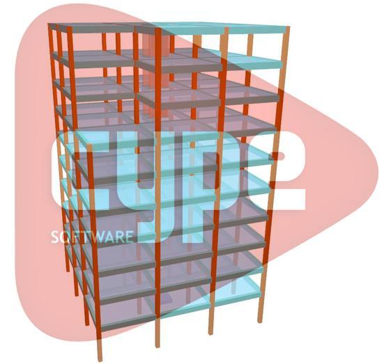
28 CYPECAD considers nearly 3% (2.95%) more seismic mass than ETABS, and so has a greater safety coefficient. 8. Additional accidental eccentricity To check the behaviour of both software programs regarding this parameter, the frame is duplicated so to create a symmetrical structure as observed in Figure 42, to analyse the torsion effects generated by these eccentricities. The coordinate origin is defined at the geometric centre to obtain the torsion with respect to the origin. Figure 42. Structure plan view [centimetres] (Source: CYPECAD) CYPECAD automatically applies an eccentricity with a value of 1/20 of the greatest dimension of the plan in the direction perpendicular to the direction of the seismic force in all the construction elements. As displayed in Figure 43, a torsional force of 1.57 tn.m, with respect to the coordinate origin that has been defined, is obtained for seismic loading in the X direction due to this default eccentricity. 28
 Logically, as it is a completely symmetrical")
 ETABS also considers the")
29 Figure 43. Forces in the columns due to the seismic loads (Source: CYPECAD) Logically, as it is a completely symmetrical structure, the total torsional forces compensate one another, and so the structure is balanced. Figure 44. Total sum of forces in the columns due to the seismic loads (Source: CYPECAD) ETABS also considers the eccentricity with respect to the diaphragm and carries out the combination of torsional forces correctly. 29
 Unlike CYPECAD, when an accidental torsional force is assigned in ETABS, a torsional force is applied per floor")
30 Figure 45. Eccentricity definition (Source: ETABS) ETABS directly displays the total values on the structure which coincide approximately with those obtained in CYPECAD. Figure 46. Total sum of the forces in the columns due to the seismic loads (Source: ETABS) Unlike CYPECAD, when an accidental torsional force is assigned in ETABS, a torsional force is applied per floor depending on the given eccentricity and shear force obtained for each vibration mode independently, and then combines the final values (including the effect due to torsion per mode) depending on the combination type that has been assigned (CQC, SRSS, etc.) 9. Wind To analyse the frame structure against wind loads, the basic frame is duplicated to create a greater tributary area. 30
31 Figure 47. Structure plan view [centimetres] (Source: CYPECAD) As with seismic loading, both software programs can generate the wind forces automatically, simply by entering the parameters required by the design code. In CYPECAD, a load coefficient is defined for each axis and acting direction. The load applied is the resultant of the sum of the leeward and windward wind at each floor and is applied at the geometric centre of the floor in each direction, which is established by the perimeter of the floor. In ETABS however, the assigning process is more tedious. The wind loads are applied to rigid diaphragms or walls, including non-structural walls. Depending on the assigned wind zone, the software carries out the following actions: Structural or non-structural area: ETABS applies loads as point loads at the corners of the element. Rigid diaphragm: ETABS calculated the geometric centre of the diaphragm. In either case, a wind pressure coefficient has to be assigned to each object area exposed to leeward or windward wind, whilst CYPECAD automatically obtains the resultant force. To compare both software programs, the generic wind method is used, bearing in mind the limitations when using this method, as it is not the usual method to apply. CYPECAD defines an editable height-pressure wind curve for a generic code and the tributary width. To equate the forces in both software programs and given that ETABS requires the forces be introduced as point loads, the intermediate heights must be interpolated, to calculate the pressure at the height of each floor of the building, which multiplied by the value of the surface area exposed to the wind, will provide the force to be defined in ETABS. 31
 Furthermore, for this generic option, load coefficients can be applied so the position of the building can be considered in case there are any")
32 Figure 48. Wind pressure curve for generic code (Source:CYPECAD) Furthermore, for this generic option, load coefficients can be applied so the position of the building can be considered in case there are any obstacles present. CYPECAD also, taking into account what is stated in the Spanish Technical Building Code CTE DB SE-AE, implements eccentricities of 5% for wind action in each direction: X and Y. The total wind load is obtained at each floor as the product of the pressure at the height in question and the exposed surface, shape factors (factor which corrects the wind depending on the shape of the building) and gust factor (amplifier which takes into account the geographical position of the building). For this example, these coefficients are taken with a value of 1. The eccentricities considered by default by CYPECAD can be seen in the following table. These generate torsion in the structure: Figure 49. Forces in the columns.wind load. (Source: CYPECAD) 32
 In ETABS, the force of the wind has to be introduced in the X and Y direction, as does the torsional moment and locate the point at which the force is to be")
33 As it is a symmetrical structure (centre of mass coincides with the stiffness centre) and the coordinate origin is also at the centre, the total torsion should be zero. Figure 50. Total sum of the forces (Source: CYPECAD) In ETABS, the force of the wind has to be introduced in the X and Y direction, as does the torsional moment and locate the point at which the force is to be applied at each floor, bearing in mind the forces must be introduced with the applied amplification coefficients. To be able to fairly compare both software programs, the wind forces introduced in ETABS are obtained using CYPECAD s wind curve shown in Figure 48. Therefore, by interpolating the values obtained from the graph in Figure 48 for the height of the first floor, equal to 3 metres, a wind pressure of 59kg/m3 is obtained acting on the following tributary area: Figure 51.Tributary area for wind action (Source: Autocad) Tributary area = 5.3 x 1.5 = 7.95 m2 Force applied in ETABS = 59 Kg/m2 x 7.95 m2 = kg = tn. 33
 It can be seen that unlike CYPECAD, ETABS does not consider the")
 Units N Mx My Qx Qy T CYPECAD tn.m 0 1,41 0 0,47 0 0 ETABS tn.m 0 0 1,407 1 0,469 0 0 Table 10.")
34 Figure 52.Wind load generic application (Source: ETABS) It can be seen that unlike CYPECAD, ETABS does not consider the eccentricity, and so omits the worst case situations in its check. Figure 53. Forces of the columns. Wind load. (Source: ETABS) Units N Mx My Qx Qy T CYPECAD tn.m 0 1,41 0 0, ETABS tn.m 0 0 1, , Table 10. Forces in columns due to wind load in CYPECAD and ETABS 1 Thesigncriteriavariesfromone software totheother. Seesection 11. Signs 34
35 10. Conclusion As the structural analysis programs can be divided into 3 phases; Pre-processing, processing and post-processing, the comparative conclusion for both software programs is done so for each phase: Pre-processing Both CYPECAD and ETABS allow for the geometry of the model to be generated using an assembly of objects, lines or finite element meshes. CYPECAD counts with a large database of different codes and bases the characterisation of the structure on these codes in a very practical manner. This manner of operating can be seen in other aspects such as the default application of the rigid diaphragm or the accidental 5% eccentricity due to wind or seismic loading. This way, users apply the required parameters by default, without the risk of not taking them into account. ETABS, however, requires the mechanical properties (modulus of elasticity, Poisson s ratio, etc.) to be introduced by users. Many of the parameters defined in this example are not available by default even though they are defined in the selected code. Therefore, ETABS requires users to have to constantly consult the selected design code. Processing The processing possibilities are related to the type of analysis that can be executed. Some observations that have been carried out prove that ETABS counts with a time-history analysis for the linear dynamic analysis and considers the effect of the construction sequence when determining the results. Post-processing The load combinations for the results output is automatic in both software programs and is based on the design code, except the force envelopes which must be defined in ETABS. As has been observed in ETABS and CYPECAD, the results of the analysis can be displayed on screen using diagrams, tables and functions, or by printing the results via text files. Furthermore, CYPECAD allows for drawings to be obtained. To summarise, both software programs focus on structural design and analysis, primarily buildings. CYPECAD stands out because of its functional nature and its ease of use when working with one of the many codes included in its database. Its user-friendly interface is also one of its main features. 35
36 ETABS counts with greater flexibility when characterising some parameters which CYPECAD does not count with due to it being limited by the design codes. 11. Sign criteria Different sign criteria have been observed between the two software programs. Shear force diagrams are displayed graphically opposite in both software programs, as can be seen, for example, in sections 5.1 and 8. Figure 54. Sign criteria. Shear. Bending moment diagrams are also defined differently. CYPECAD defines the moment on the plan in which it is contained whereas ETABS defines it with respect to the axis on which it is produced. These differences can be seen in sections 6.1 and 7.5, for example. Figure 55. Sign criteria. Moments. 36
37 Estudio comparativo entre CYPECAD Y ETABS software Pórtico Simple
CADS A3D MAX. How to model shear walls
 CADS A3D MAX How to model shear walls Modelling shear walls in A3D MAX Introduction and synopsis This paper explains how to model shear walls in A3D MAX using the `wide column rigid arm sub-frame described
S. Gandhi *1, Syed Rizwan 2
 2017 IJSRSET Volume 3 Issue 3 Print ISSN: 2395-1990 Online ISSN : 2394-4099 Themed Section: Engineering and Technology Analysis and Design of Tall Building (G+21) Using ETABS S. Gandhi *1, Syed Rizwan
0306 SEISMIC LOADS GENERAL
 0306 SEISMIC LOADS 0306.1 GENERAL Every structure, and portion thereof, including nonstructural components such as architectural, mechanical, and electrical components, shall be designed and constructed
Executive Summary Building Description: Introduction... 13
 Table of Contents Executive Summary... 2 Building Description:... 2 Report Summary:... 2 Introduction... 3 Building Description:... 3 Current Framing Layout... 4 Report Topics:... 4 Loads and Load Cases...
ANALYSIS OF BUILDINGS WITH
 1 ANALYSIS OF BUILDINGS WITH RIGID, SEMIRIGID AND PSEUDO-FLEXIBLE DIAPHRAGMS Bulent N. Alemdar, Ph.D., P.E. Rakesh Pathak, Ph.D. 1. INTRODUCTION A diaphragm is horizontal structural component and it functions
Comparative Study on Dynamic Analysis of Irregular Building with Shear Walls
 Comparative Study on Dynamic Analysis of Irregular Building with Shear Walls Le Yee Mon Civil Engineering Department, Mandalay Technological University, Mandalay, Myanmar Abstract: South East Asia including
EVALUATION OF SEISMIC BEHAVIOR OF IRREGULAR STEEL STRUCTURES IN PLAN WITH BRB AND EBF BRACES UNDER NEAR-FAULT EARTHQUAKE
 IJBPAS, January, 2015, 5(1), Special Issue: 572-581 ISSN: 2277 4998 EVALUATION OF SEISMIC BEHAVIOR OF IRREGULAR STEEL STRUCTURES IN PLAN WITH BRB AND EBF BRACES UNDER NEAR-FAULT EARTHQUAKE HOSSEIN NASERI
4.2 Tier 2 Analysis General Analysis Procedures for LSP & LDP
 4.2 Tier 2 Analysis 4.2.1 General Four analysis procedures are provided in this section: Linear Static Procedure (LSP), Linear Dynamic Procedure (LDP), Special Procedure, and Procedure for Nonstructural
Structural Design of Super High Rise Buildings in High Seismic Intensity Area
 Structural Design of Super High Rise Buildings in High Seismic Intensity Area Jianbo Zheng School of Architectural Engineering, Binzhou University, Binzhou, 256600, China zjb2006@163.com Abstract The structure
EngSolutions RCB. Analysis & Design of Reinforced Concrete Buildings for Earthquake and Wind Forces
 EngSolutions RCB Analysis & Design of Reinforced Concrete Buildings for Earthquake and Wind Forces EngSolutions RCB is a structural engineering-software for 3D analysis and design of reinforced concrete
Engr. Thaung Htut Aung M. Eng. Asian Institute of Technology Deputy Project Director, AIT Consulting
 Engr. Thaung Htut Aung M. Eng. Asian Institute of Technology Deputy Project Director, AIT Consulting Selection of Structural systems Load paths Materials Approximate sizing of members Primary mechanisms
INVESTIGATION ON NONLINEAR ANALYSIS OF EXISTING BUILDING AND INTRODUCING SEISMIC RETROFITTING OUTLINES WITH CASE STUDY
 13 th World onference on Earthquake Engineering Vancouver, B.., anada August 1-6, 4 Paper No. 356 INVESTIGATION ON NONLINEAR ANALYSIS OF EXISTING BUILDING AND INTRODUING SEISMI RETROFITTING OUTLINES WITH
Tekla Structural Designer 2017
 Tekla Structural Designer 2017 Engineer s Handbooks (AS) March 2017 (5.0.0.7) 2017 Trimble Solutions Corporation part of Trimble Navigation Ltd. Table of Contents Wind Modeling Handbook... 1 Application
Torsional and Seismic Behavior of Shear Wall Dominant Flat Plate Buildings
 Torsional and Seismic Behavior of Shear Wall Dominant Flat Plate Buildings Ramya S R 1, Dr. P M Ravindra 2 1M. Tech Student, Department of Civil Engineering, Bangalore Institute of Technology, Bengaluru-
midas Gen Release Note
 Gen 2014 Integrated Design System for Building and General Structures midas Gen Release Note Release Date : May. 28, 2014 Product Ver. : 2014(v2.1) Gen 2014 (v2.1) Release Note Gen 2014 (v2.1) Release
Example of a modelling review Roof truss
 Example of a modelling review Roof truss Iain A MacLeod The Structure Figure gives an elevation and connection details for a roof truss. It is supported at each end on masonry walls. The trusses are at
Design of buildings using EC8
 Design of buildings using EC8 & 1 can be applied to all buildings and is obligatory for buildings which do not satisfy the regularity criteria specified by EC8. The response of all modes of vibration contributing
Response of TBI case study buildings
 Response of TBI case study buildings ANALYSIS OF STEEL BUILDING Pierson Jones & Farzin Zareian May 7 th, 2010 Introduction Three 40-story Building BRBF Systems building Structural and Earthquake Engineering
Modelling and Analysis of Irregular Geometrical Configured RCC Multi- Storey Building Using Shear Wall
 Kalpa Publications in Civil Engineering Volume 1, 2017, Pages 388 397 ICRISET2017. International Conference on Research and Innovations in Science, Engineering &Technology. Selected papers in Civil Engineering
3. Analysis Procedures
 3. Analysis Procedures 3.1 Scope This chapter sets forth requirements for analysis of buildings using the Systematic Rehabilitation Method. Section 3.2 specifies general analysis requirements for the mathematical
Customizable and Integrated Configuration. Modeling Environment. Advanced Meshing Tools
 Model, analyze and design structures regardless of geometric complexity, material type, loading conditions, nonlinear effects, or design codes. Easy enough for simple projects, powerful enough for the
Precast Concrete Bearing Wall Panel Design (Alternative Analysis Method) (Using ACI )
 (Using ACI )") Precast Concrete Bearing Wall Panel Design (Alternative Analysis ethod) (Using ACI 318-14) Precast Concrete Bearing Wall Panel Design (Alternative Analysis ethod) (Using ACI 318-14) A structural precast
Precast Concrete Bearing Wall Panel Design (Alternative Analysis ethod) (Using ACI 318-14) Precast Concrete Bearing Wall Panel Design (Alternative Analysis ethod) (Using ACI 318-14) A structural precast
STUDY ON TALL BUILDING STRUCTURE ANALYSIS
 STUDY ON TALL BUILDING STRUCTURE ANALYSIS Liu Huafeng 1, Zhao Ning 2 ABSTRACT TBSA (Tall Building Structure Analysis) is a three-dimension analysis program for tall buildings based on a member structure
School of Engineering and Applied Science Building Miami University, Oxford, OH Technical Assignment 3 December 3, 2007
 School of Engineering and Applied Science Building Miami University, Oxford, OH Technical Assignment 3 December 3, 2007 Jonathan Kirk AE 481W Senior Thesis The Pennsylvania State University Faculty Advisor:
COMPARISON OF MULTISTORY WALL RESULTS BETWEEN ADAPT-EDGE 1 AND ETABS 2 CONCRETE FRAME WITH SHEARWALLS
 Your Partner in Structural Concrete Design TN500_EDGE_Etabs_Comp_06132016 COMPARISON OF MULTISTORY WALL RESULTS BETWEEN ADAPT-EDGE 1 AND ETABS 2 CONCRETE FRAME WITH SHEARWALLS INTRODUCTION This Technical
Chapter 13 SEISMICALLY ISOLATED STRUCTURE DESIGN REQUIREMENTS
 Chapter 13 SEISMICALLY ISOLATE STRUCTURE ESIGN REQUIREMENTS 13.1 GENERAL 13.1.1 Scope. Every seismically isolated structure and every portion thereof shall be designed and constructed in accordance with
ACCURATE LINEAR AND NONLINEAR SEISMIC SSI ANALYSIS BASED ON ANSYS FE MODELING USING EXTENDED SASSI METHODOLOGY
 Transactions, SMiRT-24 II, Paper 468 ACCURATE LINEAR AND NONLINEAR SEISMIC SSI ANALYSIS BASED ON ANSYS FE MODELING USING EXTENDED SASSI METHODOLOGY Dan M. Ghiocel 1, Mike Saremi 2 1 Chief of Engineering
ADAPT-PT 2010 Tutorial Idealization of Design Strip in ADAPT-PT
 ADAPT-PT 2010 Tutorial Idealization of Design Strip in ADAPT-PT Update: April 2010 Copyright ADAPT Corporation all rights reserved ADAPT-PT 2010-Tutorial- 1 Main Toolbar Menu Bar View Toolbar Structure
Modal-spectral analysis of a gas storage tank.
 Modal-spectral analysis of a gas storage tank. Description of the structure: A Spherical tank gas storage is formed by: 1.- S-355 steel sphere plate elements of 1.5 cm thickness. 2.- Eight vertical posts
Base Shear Scaling. B. J. Davidson. Compusoft Engineering Ltd.
 Base Shear Scaling B. J. Davidson Compusoft Engineering Ltd. 008 NZSEE Conference ABSTRACT: The base shear scaling requirements of NZS1170.5 are sometimes difficult to implement for the complex buildings
By Denis Mitchell and Patrick Paultre Seismic Design
 11 By Denis Mitchell and Patrick Paultre Seismic Design 11.1 Introduction... 11 3 11.2 Seismic Design Considerations... 11 5 11.3 Loading Cases... 11 5 11.4 Design of a Six-Storey Ductile Moment-Resisting
Design of buildings using EC8 Configuration of the structural system
 Design of buildings using EC8 Configuration of the structural system Regularity in plan and elevation 1 For the purpose of seismic design, building structures are distinguished as regular and non-regular.
ADAPT-PTRC 2016 Getting Started Tutorial ADAPT-PT mode
 ADAPT-PTRC 2016 Getting Started Tutorial ADAPT-PT mode Update: August 2016 Copyright ADAPT Corporation all rights reserved ADAPT-PT/RC 2016-Tutorial- 1 This ADAPT-PTRC 2016 Getting Started Tutorial is
Dimensionamento Estrutural de uma Ponte Canal. Structural Design of a Canal Bridge. Francisco Barbosa Alves de Moura. Introduction
 Dimensionamento Estrutural de uma Ponte Canal Structural Design of a Canal Bridge Francisco Barbosa Alves de Moura IST, Technical University of Lisbon, Portugal Key Words: Structural Design, Canal Bridge,
Seismic Analysis of RC Shear Wall Frame Buildings with and Without Openings in Shear Wall
 Seismic Analysis of RC Shear Wall Frame Buildings with and Without Openings in Shear Wall Syed Mohammad Umar 1, Rizwanullah 2 1M-Tech (Structure and Foundation Engineering), 2 Assistant Professor Department
Base isolation. Philippe Bisch IOSIS, EGIS group. EUROCODE 8 Background and Applications
 EUROCODE 8 Background and Applications Dissemination of information for training Lisbon, 10-11 February 2011 1 Base isolation Philippe Bisch IOSIS, EGIS group EUROCODE 8 Background and Applications BASE
Seismic Assessment and Retrofitting of an S Shape Building with Expansion Joints.
 Seismic Assessment and Retrofitting of an S Shape Building with Expansion Joints. A. Plumier 1, V. Denoël 1, L. Sanchez 1, C. Doneux 1, V. Warnotte 1, W. Van Alboom 2 1 Department of Mechanics of Materials
Alexis Pacella Structural Option Dr. Schneider Lexington II, Washington D.C. Technical Report #3 November 21,
 1 Executive Summary: Lateral System Analysis and Confirmation Design is an depth look at the lateral system of Lexington II and the loads of which it must carry. The structural system of Lexington II is
Release Note DESIGN OF CIVIL STRUCTURES. Release Date : SEP. 1, 2015 Product Ver. : Civil 2016 (v1.1)
") Release Note Release Date : SEP. 1, 2015 Product Ver. : Civil 2016 (v1.1) DESIGN OF CIVIL STRUCTURES Integrated Solution System for Bridge and Civil Engineering Enhancements Analysis & Design 3 (1) UK
Release Note Release Date : SEP. 1, 2015 Product Ver. : Civil 2016 (v1.1) DESIGN OF CIVIL STRUCTURES Integrated Solution System for Bridge and Civil Engineering Enhancements Analysis & Design 3 (1) UK
Introduction to. Asian Center for Engineering Computations and Software. ACECOMS & AIT Solutions 1
 Introduction to 2016 Asian Center for Engineering Computations and Software ACECOMS & AIT Solutions 1 ETABS 2016 is The ultimate integrated software package for the structural analysis, design and detailing
Consideration of torsional irregularity in Modal Response Spectrum Analysis
 Earthquake Resistant Engineering Structures X 209 Consideration of torsional irregularity in Modal Response Spectrum Analysis O. A. Mohamed & O. A. Abbass Department of Civil Engineering, Abu Dhabi University,
Seismic Analysis & Design of 10 Story RC Building
 Seismic Analysis & Design of 10 Story RC Building (Time History Analysis) Using ETABS (Metric Units) 0.3 yg 0.2 0.1 0 0 2 4 6 8 10 12-0.1-0.2-0.3 Table of Content Objective 5 Problem 5 Step by Step 11
PERFORMANCE BASED ANALYSIS OF R.C.C. FRAMES
 PERFORMANCE BASED ANALYSIS OF R.C.C. FRAMES Mrugesh D. Shah M.E Structure student, B.V.M Engineering College Atul N. Desai Associate professor. B.V.M Engineering College Sumant B Patel Associate Professor,
Inelastic Torsional Response of Steel Concentrically Braced Frames
 Inelastic Torsional Response of Steel Concentrically Braced Frames R. Comlek, B. Akbas & O. Umut Gebze Institute of Technology, Gebze-Kocaeli, Turkey J. Shen & N. Sutchiewcharn Illinois Institute of Technology,
Stay Tuned! Practical Cable Stayed Bridge Design
 midas Civil Stay Tuned! Practical Cable Stayed Bridge Design 2017 Francesco Incelli I. Introduction II. Modeling of the cable-stayed bridge a. Bridge wizard b. Girder Cross Section III. Nonlinear Effect
RESPONSE STUDY OF MULTI-STORIED BUILDINGS WITH PLAN IRREGULARITY SUBJECTED TO EARTHQUAKE AND WIND LOADS USING LINEAR STATIC ANALYSIS
 RESPONSE STUDY OF MULTI-STORIED BUILDINGS WITH PLAN IRREGULARITY SUBJECTED TO EARTHQUAKE AND WIND LOADS USING LINEAR STATIC ANALYSIS Ramesh Konakalla 1, Ramesh Dutt Chilakapati 2, Dr Harinadha Babu Raparla
SIMPLE INVESTIGATIONS OF TENSILE MEMBRANE ACTION IN COMPOSITE SLABS IN FIRE
 SIMPLE INVESTIGATIONS OF TENSILE MEMBRANE ACTION IN COMPOSITE SLABS IN FIRE By Ahmed Allam 1, Ian Burgess 1 and Roger Plank 1 Department of Civil and Structural Engineering, University of Sheffield, UK
CE 160 SAP 2000 Notes for 2D Problems. Element and Joint Drawing Tools Global Coordinates of Cursor Position Units in View Window
 CE 160 SAP 2000 Notes for 2D Problems SAP 2000 Main Screen Highlights Title of View Model Lock Zoom Controls Global Coordinate Plane of View Window Pull Down Menus Element and Joint Drawing Tools Global
SEISMIC CONSIDERATIONS FOR TELECOMMUNICATION TOWERS MOUNTED ON BUILDING ROOFTOPS
 13 th World Conference on Earthquake Engineering Vancouver, B.C., Canada August 1-6, 2004 Paper No. 1988 SEISMIC CONSIDERATIONS FOR TELECOMMUNICATION TOWERS MOUNTED ON BUILDING ROOFTOPS Ghyslaine McCLURE
Fagà, Bianco, Bolognini, and Nascimbene 3rd fib International Congress
 COMPARISON BETWEEN NUMERICAL AND EXPERIMENTAL CYCLIC RESPONSE OF ALTERNATIVE COLUMN TO FOUNDATION CONNECTIONS OF REINFORCED CONCRETEC PRECAST STRUCTURES Ettore Fagà, Dr, EUCENTRE, Pavia, Italy Lorenzo
Response Analysis of an RC Cooling Tower Under Seismic and Windstorm Effects D. Makovička
 Response Analysis of an RC Cooling Tower Under Seismic and Windstorm Effects D. Makovička The paper compares the RC structure of a cooling tower unit under seismic loads and under strong wind loads. The
Lateral System Analysis and Confirmation Design November 15, 2004
 Jonathan Hill Structural AE Faculty Consultant Dr. Hanagan Lynde and Harry Bradley School of Technology & Trade Milwaukee, Wisconsin Lateral System Analysis and Confirmation Design November 15, 2004 Executive
STRUCTURAL APPLICATIONS OF A REINFORCED CONCRETE BEAM-COLUMN-SLAB CONNECTION MODEL FOR EARTHQUAKE LOADING
 STRUCTURAL APPLICATIONS OF A REINFORCED CONCRETE BEAM-COLUMN-SLAB CONNECTION MODEL FOR EARTHQUAKE LOADING B.B. Canbolat 1 1 Assistant Professor, Dept. of Civil Engineering, Middle East Technical University,
Seismic Behaviour of Reinforced Concrete Framed Buildings with Columns of Different Heights within One Storey
 Volume-4, Issue-5, October-2014, ISSN No.: 2250-0758 International Journal of Engineering and Management Research Available at: www.ijemr.net Page Number: 37-41 Seismic Behaviour of Reinforced Concrete
Analysis of a Multi-Tower Frame Structure connected at different levels using ETABS
 Analysis of a Multi-Tower Frame Structure connected at different levels using ETABS RISHABH SISODIA 1, N. Tej Kiran 2, K. Sai Sekhar Reddy 3 1Student, Dept. of Structural and Geotechnical Engineering,
LEARNING OF ETABS. 15 ft
 LEARNING OF ETABS Ram Krishna Mazumder, Institute of Earthquake Engineering Research, Chittagong University of Engineering and Technology, Chittagong 4349, Bangladesh rkmazumder@gmail.com +8801712862281
International Journal of Engineering and Techniques - Volume 4 Issue 2, Mar Apr 2018
 RESEARCH ARTICLE Seismic Analysis of Steel Frames Subjected to Braced Connections Matha Prasad Adari* *Assistant Professor, Dept. of Civil Engineering. NSRIT Visakhapatnam, Andhra Pradesh, INDIA. 1.INTRODUCTION
A Guide for the Interpretation of Structural Design Options for Residential Concrete Structures
 CFA Technical Note: 008-2010 A Guide for the Interpretation of Structural Design Options for Residential Concrete Structures CFA Technical This CFA Technical Note is intended to serve as a guide to assist
Design check of BRBF system according to Eurocode 8 Use of pushover analysis
 2010 Design check of BRBF system according to Eurocode 8 Use of pushover analysis This report presents a simple computerbased push-over analysis for a steel structure with Buckling Restrained Braced Frame
Design Criteria For Reinforced Concrete Columns Under Seismic Loading
 Design Criteria For Reinforced Concrete Columns Under Seismic Loading J. Selwyn Babu & N. Mahendran 2 Associate Professor in Civil Engineering, PSNA College of Engineering and Technology, Dindigul 2 Professor
Structural Engineering, Mechanics, and Materials. Preliminary Exam - Structural Design
 Fall Semester 2018 Preliminary Exam - Structural Design A small building is located in downtown Berkeley. The structural system, either structural steel or reinforced concrete, comprises gravity framing
User Elements Developed for the Nonlinear Dynamic Analysis of Reinforced Concrete Structures
 Research Collection Conference Paper User Elements Developed for the Nonlinear Dynamic Analysis of Reinforced Concrete Structures Author(s): Wenk, Thomas; Linde, Peter; Bachmann, Hugo Publication Date:
Modeling and Design of Bridge Super Structure and Sub Structure
 Topic 3 Day 2 Modeling and Design of Bridge Super Structure and Sub Structure Naveed Anwar 1. Over view of Bridge Design Process and Bridge Types 2. Advances and recent trends in Modeling and Analysis
IS 1893 and IS Codal Changes
 IS 1893 and IS 13920 Codal Changes Reading between the lines Alpa Sheth IS 1893-2016 Changes In Estimation Of The Hazard a) Design spectra extended up to natural period up of 6 s; b) Same design response
MULTI-STOREY BUILDINGS - II
 38 MULTI-STOREY BUILDINGS - II 1.0 INTRODUCTION Modern design offices are generally equipped with a wide variety of structural analysis software programs, invariably based on the stiffness matrix method.
Italic words marked in cyan are linked to their definition.
 This document gives a detailed summary of the new features and modifications of FEM-Design version 13. We hope you will enjoy using the program and its new tools and possibilities. We wish you success.
Question Paper Code : 11410
 Reg. No. : Question Paper Code : 11410 B.E./B.Tech. DEGREE EXAMINATION, APRIL/MAY 2011 Fourth Semester Mechanical Engineering ME 2254 STRENGTH OF MATERIALS (Common to Automobile Engineering and Production
Case Study: Challenges of a Single-layer Reticulated Dome
 Case Study: Challenges of a Single-layer Reticulated Dome Naveed Anwar, Pramin Norachan, Thaung Htut Aung AIT Consulting, Asian Institute of Technology, Bangkok, Thailand Contact: nanwar@ait.asia Abstract
Proceedings of the 3rd International Conference on Environmental and Geological Science and Engineering
 Modeling of Hysteretic Damper in Three-Story Steel Frame Subjected to Earthquake Load Mohammad Saeed Masoomi 1, Siti Aminah Osman 1, and Shahed Shojaeipour 2 Department Civil and Structural Engineering
Tekla Structural Designer 2016
 Tekla Structural Designer 2016 Reference Guides (AS Non-Composite Steel) April 2016 2016 Trimble Solutions Corporation part of Trimble Navigation Ltd. Table of Contents Loading - Australian Standards...
Two-way slabs. Flat plate with or without drop panels / capitals
 Two-way slabs Two-way slab behavior is described by plate bending theory which is a complex extension of beam bending. Codes of practice allow use of simplified methods for analysis and design of two-way
ANNEX 10. Special requirements recommended for structures subject to seismic actions. 1 Scope. 2 Basis of design. 2.1 Fundamental requirements
 ANNEX 10 Special requirements recommended for structures subject to seismic actions 1 Scope This Annex sets out the special requirements which are recommended for structural concrete structures subject
BOUNDARY CONDITIONS OF SHEAR WALLS IN MULTI-STOREY MASONRY STRUCTURES UNDER HORIZONTAL LOADINGS
 BOUNDARY CONDITIONS OF SHEAR WALLS IN MULTI-STOREY MASONRY STRUCTURES UNDER HORIZONTAL LOADINGS K. ZILCH Professor, Institute of Building Materials and Structures Chair of Concrete Structures Technische
How to model Mohr-Coulomb interaction between elements in Abaqus
 How to model Mohr-Coulomb interaction between elements in Abaqus Problem description We want to model the interaction between two masonry walls and a timber beam. The elements are connected by special
Structural Dynamics and Earthquake Engineering
 Structural Dynamics and Earthquake Engineering Course 10 Design of buildings for seismic action (2) Course notes are available for download at http://www.ct.upt.ro/users/aurelstratan/ Combination of the
Table of contents. EC3 Steel Design - Class 4 calculation of effective characteristics... 5
 What's New 2018 R2 Table of contents NEW OPTIONS & IMPROVEMENTS... 5 EC3 Steel Design - Class 4 calculation of effective characteristics... 5 Optimization of theoretical reinforcement according to EC2
NON-LINEAR STATIC PUSHOVER ANALYSIS FOR MULTI-STORED BUILDING BY USING ETABS
 NON-LINEAR STATIC PUSHOVER ANALYSIS FOR MULTI-STORED BUILDING BY USING ETABS Polupalli Victor Paul 1, K Sampath Kumar 2 1 PG Student, Dept of Civil Engineering, Nova College of Engineering & Technology,
COMPARISON OF A REINFORCED CONCRETE BUILDING STRENGTHRND WITH VARIOUS METHODS
 COMPARISON OF A REINFORCED CONCRETE BUILDING STRENGTHRND WITH VARIOUS METHODS Farnaz ALINOORI 1 and Kadir GÜLER 2 ABSTRACT The earthquake performance of a school building having three stories which has
Comparison between Seismic Behavior of Suspended Zipper Braced Frames and Various EBF Systems
 Comparison between Seismic Behavior of Suspended Zipper Braced Frames and Various EBF Systems A. Niknam 1, A. Sharfaei 2 1- Assistant Professor, Civil Engineering Faculty, University of Science & Technology,
Multi-Story Solid Tilt-Up Wall Panel Analysis and Design (ACI 551)
") Multi-Story Solid Tilt-Up Wall Panel Analysis and Design (ACI 551) Span 1 Span 2 Span 3 Span 4 Reinforced Concrete Multi-Story Tilt-Up Wall Panel Analysis (ACI 551) Tilt-up is form of construction with
Multi-Story Solid Tilt-Up Wall Panel Analysis and Design (ACI 551) Span 1 Span 2 Span 3 Span 4 Reinforced Concrete Multi-Story Tilt-Up Wall Panel Analysis (ACI 551) Tilt-up is form of construction with
International Journal of Scientific & Engineering Research, Volume 7, Issue 6, June ISSN
 International Journal of Scientific & Engineering Research, Volume 7, Issue 6, June-26 36 DIAGRID STRUCTURAL SYSTEM FOR R.C.FRAMED MULTIED BUILDINGS Harshita Tripathi, Dr. Sarita Singla Abstract- One of
Seismic Design of Cast-in-Place Concrete Diaphragms, Chords and Collectors
 DESIGN OF TALL BUILDINGS: TRENDS AND ADVANCEMENTS FOR STRUCTURAL PEFORMANCE November 10, 2016 Pathumthani, Thailand Seismic Design of Cast-in-Place Concrete Diaphragms, Chords and Collectors Pramin Norachan
NONLINEAR STATIC ANALYSIS OF R.C.C. FRAMES (Software Implementation ETABS 9.7)
") NONLINEAR STATIC ANALYSIS OF R.C.C. FRAMES (Software Implementation ETABS 9.7) Mrugesh D. Shah M.E Structure student, B.V.M Engineering College Abstract:- Nonlinear static analysis is an iterative procedure
NONLINEAR STATIC ANALYSIS OF R.C.C. FRAMES (Software Implementation ETABS 9.7) Mrugesh D. Shah M.E Structure student, B.V.M Engineering College Abstract:- Nonlinear static analysis is an iterative procedure
The Effect of Frame Geometry on the Seismic Response of Self-Centering Concentrically- Braced Frames
 International Journal of Civil and Environmental Engineering 6 212 The Effect of Frame Geometry on the Seismic Response of Self-Centering Concentrically- Braced Frames David A. Roke and M. R. Hasan Abstract
SEISMIC ANALYSIS OF SIX STOREYED RC FRAMED BUILDING WITH BRACING SYSTEMS
 SEISMIC ANALYSIS OF SIX STOREYED RC FRAMED BUILDING WITH BRACING SYSTEMS ABSTRACT Megha Kalra Assistant Professor, The North Cap University, Gurgaon(India) Multistoreyed buildings are most affected by
SEISMIC ANALYSIS OF SIX STOREYED RC FRAMED BUILDING WITH BRACING SYSTEMS
 SEISMIC ANALYSIS OF SIX STOREYED RC FRAMED BUILDING WITH BRACING SYSTEMS ABSTRACT Megha Kalra Assistant Professor, The North Cap University, Gurgaon(India) Multistoreyed buildings are most affected by
GENERAL CONSIDERATIONS ON STRUCTURAL REGULARITY
 13 th World Conference on Earthquake Engineering Vancouver, B.C., Canada August 1-6, 2004 Paper No. 947 GENERAL CONSIDERATIONS ON STRUCTURAL REGULARITY Aurelio Ghersi 1 SUMMARY In the last decades the
SAFI TM 3D. Why SAFI? Among SAFI applications we can find: Structural Analysis and Strength of Materials
 SAFI 3D is a robust and reliable structural software designed with the latest technological innovations in its field and is equipped with a sophisticated, ergonomic and user friendly graphical user interface.
A Performance Based Evaluation of a Wall- Frame Structure Employing the Pushover Analysis Tool
 A Performance Based Evaluation of a Wall- Frame Structure Employing the Pushover Analysis Tool Kiran Kamath 1, Jose Camilo Karl Barbosa Noronha 2, Sachin Hirannaiah 3 Professor, Dept. of Civil Engineering,
2.15 Tokamak Seismic Analysis
 2.15 Tokamak Seismic Analysis 2.15.1 Introduction 1 2.15.2 Input Conditions 3 2.15.2.1 Design Response Spectra 3 2.15.2.2 Damping Coefficients 4 2.15.3 Model Overview 4 2.15.4 Main Results Under SL-2 Seismic
1000 CONTINENTAL SQUARE
 1000 CONTINENTAL SQUARE KING OF PRUSSIA, PENNSYLVANIA Carter Davis Hayes Structural Option January 13, 2008 Advisor: Dr. Hanagan TABLE OF CONTENTS TABLE OF CONTENTS... 2 EXECUTIVE SUMMARY... 3 I. STRUCTURAL
Seismic Evaluation of a 1930 Steel Bridge with Lightly Reinforced Concrete Piers
 Seismic Evaluation of a 1930 Steel Bridge with Lightly Reinforced Concrete Piers R. Tinawi & M. Leclerc École Polytechnique de Montréal, Canada D. Mitchell McGill University, Canada A. Massad Hydro-Québec,
ADAPT PT7 TUTORIAL FOR BEAM FRAME 1
 ADAPT PT7 TUTORIAL FOR BEAM FRAME 1 Technical Note Structural Concrete Software System TN189_PT7_tutorial_beam_frame 012705 1 BEAM FRAME The objective of this tutorial is to demonstrate the step-by-step
Comparative Analysis and Design of Flat and Grid Slab System with Conventional Slab System
 Comparative Analysis and Design of Flat and Grid Slab System with Conventional Slab System Syed Abdul Qavi 1, Syed Khaleelullah Shah Quadri 2 Syed Farrukh Anwar 3 1 PG Student, M.tech in Structural engineering,
Seismic Analysis of Truss Bridges with Tall Piers
 Journal P Krishi Sanskriti Publications http: Seismic Analysis of Truss Bridges with Tall Piers Akil Ahmed 1 and Jameel Ahmed 2 1,2 Deptt of Civil Engineering Jamia Millia Islamia, Jamia Nagar, New Delhi
SEISMIC EVALUATION OF A CONCRETE STRUCTURE WITH VARIOUS PERCENTAGE OF SYMETRY IN ACCORDANCE WITH PERFORMANCE- BASED DESIGN
 SEISMIC EVALUATION OF A CONCRETE STRUCTURE WITH VARIOUS PERCENTAGE OF SYMETRY IN ACCORDANCE WITH PERFORMANCE- BASED DESIGN Alireza M.Goltabar, Hosein Ali Beygi, R. Shamstabar kami 3, H. Jalali Assistance
Department of Civil Engineering, SKP Engg. College, Tiruvanamalai, TN, India
 DESIGN AND ANALYSIS OF MULTI- STOREYED BUILDING UNDER STATIC AND DYNAMIC LOADING CONDITIONS USING ETABS Balaji.U. A 1, Mr. Selvarasan M.E. B 2 1 PG Student, 2 Asst.Professor Department of Civil Engineering,
SEISMIC DESIGN OF STRUCTURE
 SEISMIC DESIGN OF STRUCTURE PART I TERMINOLOGY EXPLANATION Chapter 1 Earthquake Faults Epicenter Focal Depth Focus Focal Distance Epicenter Distance Tectonic Earthquake Volcanic Earthquake Collapse Earthquake
Seismic Response of RC Building Structures using Capacity Spectrum Method with included Soil Flexibility
 Seismic Response of RC Building Structures using Capacity Spectrum Method with included Soil Flexibility G. N. Cvetanovska, R. Apostolska and J. Cvetanovska University "Ss. Cyril and Methodius", Institute