COMMERCIAL CONDUIT RULES AND REGULATIONS
|
|
|
- Augusta Goodwin
- 6 years ago
- Views:
Transcription

1 Electric Engineering Division COMMERCIAL CONDUIT RULES AND REGULATIONS S:\COO_ACM_US_Electric_Telecommunications\COO_ET_Engineering\Conduit Policies B - 1
 351-6620 Fax: (352) 401-6961 Electric Engineering Division Dear Developer: Over the next few months, the City of Ocala Utility Services (OUS) will be working")
2 1805 NE 30th Ave., Bldg. 400 Ocala, FL Phone: (352) Fax: (352) Electric Engineering Division Dear Developer: Over the next few months, the City of Ocala Utility Services (OUS) will be working closely with you and your contractors to install the electrical conduit system for your project. We in the Electric Engineering Division are looking forward to working with your contractors and want the installation to proceed as smooth as possible. Attached, please find the OUS Commercial Conduit Rules and Regulations for use by your electrical conduit contractor. If the contractor has any questions that are not addressed in this guide, please contact the OUS representative responsible for the project. Respectfully Ocala Utility Services Engineering Division B - 2
3 TABLE OF CONTENTS i. LETTER TO DEVELOPER... 2 I. RULES AND REGULATIONS A. TABLE OF CONTENTS... 3 B. TERMS AND DEFINITIONS... 4 C. DEVELOPER S RESPONSIBILITIES... 6 D. TRENCH SPECIFICATIONS AND PROCEDURES... 7 E. REQUIREMENTS FOR JOINT USE OF TRENCH... 8 F. CONDUIT SPECIFICATIONS... 9 G. CONDUIT PROCEDURES 1. Raceways Riser Stub-ups Transformer Locations Primary Cabinet Locations H. SUMMARY I. SYMBOLS J. EXHIBITS 1. Secondary/Service Riser Stub-up Installation - Exhibit 1C Concrete Encasement and Bridge Placement - Exhibit Typical 1-phase and 3-phase Transformer Location - Exhibit 4C Typical 1-phase Primary Cabinet Location - Exhibit Typical 3-phase Primary Cabinet Stub-up - Exhibit Typical Stub-up Termination Point - Exhibit Transformer Placement in Easement - Exhibit Warning Tape Placement - Exhibit Conduit Clearances-Joint Use Trench - Exhibit Minimum Vertical Clearance at Crossings - Exhibit Minimum Horizontal Clearance Around Equipment - Exhibit Typical Street Light Vault Location Exhibit Primary Riser Stub-up Exhibit Secondary Vault Stub-up Exhibit Temporary Construction Service Installation Exhibit Multiple Conduits in Trench Exhibit Directional Bore Conversion Exhibit Meter Socket Spacing Requirements Exhibit 21C Unacceptable Combination Meter Can K. SUPPLEMENTAL SHEETS (Site specific and provided by OUS as needed) 3 B - 3
4 TERMS AND DEFINITIONS Conduit System: Conduit Stub-up: Developer: Utility Easement: Ells: Final Grade: Overhead Construction: Point of Service: Primary Cable: Primary Riser: Primary Cabinet: Primary Conduit: Any combination of duct, conduits, cabinets and vaults joined to form an integrated whole. Any vertical length of conduit that allows above ground access to an underground electrical conduit raceway. Architect, engineer, electrician, owner, or contractor responsible for the installation of the electric facilities. A legal document giving the Utility limited use of private property to provide electric service. Heavy wall rigid Schedule 40 PVC conduit elbow; gray in color; Electrical grade, radius according to size: 2, 3, 4 diameter = 24 radius; 6 diameter = 36 radius. The grade at the time of completion of the site including all buildings. The standard placement of electric distribution lines on wood, metal, composite or concrete poles above ground. The point within a parcel of property that is determined the closest and most reasonable for Ocala Utility Services to provide electric service. Typically where OUS facilities end and the customer s begin. Electrical cable used for the purpose of transmitting high voltage (above one thousand volts) from one point to another. Any vertical length of conduit used to transition overhead primary to underground primary. An above ground metal enclosure, used by the utility for joining primary electrical cables. Conduit intended for use with primary cable. Raceway: Right-of-way: An enclosed channel designed expressly for holding wire or cables. A conduit is a raceway, so is a duct. A strip of land occupied or intended to be occupied by a road, crosswalk, railroad, electric power line, oil or gas pipeline, water main, sanitary or storm sewer main, or for similar use. Riser Stub-up: A vertical length of conduit installed above ell at pole or stub-up location. 4 B - 4
5 Secondary Cabinet: Secondary Cable: Secondary Riser: Secondary Vault: Service Wire: Secondary/Service Conduit: Sweep: Transformer: Transformer Pad: Underground Construction: Warning Tape: Junction point to terminate secondary conductor. Above ground cabinet usually contains Utility cable and customer cable within the same enclosure. Electrical cable used for the purpose of transmitting low voltage (600 volt cable) from one point to another. Any vertical length of conduit used to transition overhead secondary to underground secondary. A below ground fiberglass enclosure, used for joining secondary electrical cables. Cable between OUS Electric facilities and meter pedestals or meters. Conduit intended for use with secondary or service cable. Raceway between OUS facilities and the customer s meter. A gradual curve of the conduit raceway used to change direction of the conduit run. Electrical device used for converting voltage levels. A ground mounted platform used to support a transformer. The placement of electric primary and/or secondary cable and conduit below final grade. Six (6) inch wide red warning tape installed in all trenches above conduit system at twelve (12) inches below final grade. 5 B - 5
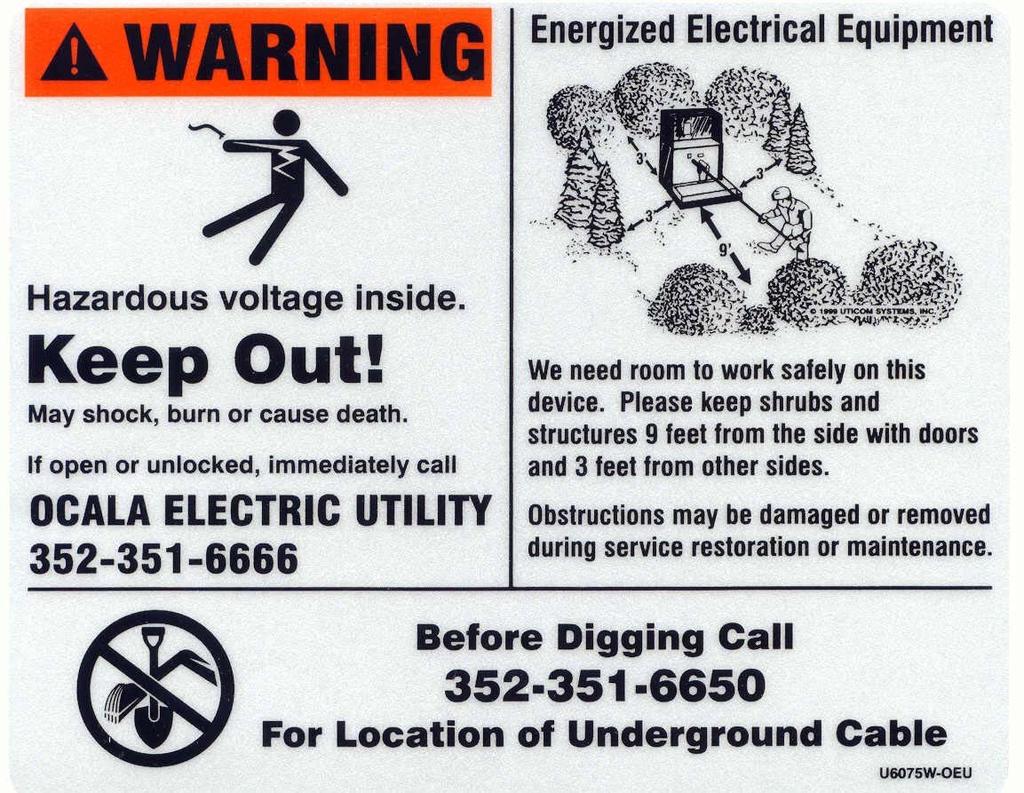
6 DEVELOPERS RESPONSIBILITIES 1. Installation of the underground electric conduit system shall not begin until the contractor is issued prints stamped APPROVED FOR CONSTRUCTION and initialed by the Engineer assigned to the project. Any print(s) that are unstamped or stamped preliminary cannot be used for construction. Field changes to the conduit design must be approved by OUS in writing. 2. Construction site must be within six (6) inches of final grade or the Developer must provide elevations for the conduit route before any conduit installation may begin. 3. The conduit system must be inspected by an authorized OUS inspector, Electric Engineering Division, prior to closing the trench. Failure to comply will result in re-opening of the trench at Developer s expense. 4. The Developer will be responsible for staking all electrical cable routes, cabinets, vaults and transformer locations as indicated in the approved construction drawings supplied by OUS. Any relocation needed after the conduit is installed will be at the Developer s expense. 5. The Developer shall be responsible for supplying property markers, right-of-way markers, radius of curvature markers, sidewalk markers, and curb markers as needed for the electrical conduit installation before, during and after construction. 6. The Developer shall be held responsible and liable for the electrical conduit system until OUS Electric Engineering Division accepts it. The conduit installed will be officially accepted when OUS successfully installs cable in the conduit system. All as-built drawings must be submitted to the Electric Engineering Division prior to final acceptance. 7. The Developer shall be responsible to ensure that shrubs, plants, and structures are kept nine (9) feet from the front side of padmount transformers, and three (3) feet from the other sides. OUS reserves the right to remove any obstructions without notice to the owner if any deviations from this standard are encountered in the field. (SEE EXHIBIT 12). 8. City, County or State Road Permits and Railroad Permits will be obtained by OUS as necessary. No construction can be started until all applicable approved permits are received. 9. If a temporary construction service is required the meter post will be installed at the right side rear of the transformer or the rear of the secondary vault. (SEE EXHIBIT 18) 10. The Developer shall provide service conduit and conductor from the meter can to the secondary vault or padmounted transformer. These specifications reflect minimum requirements and OUS reserves the right to alter or impose more stringent requirements as necessary for good engineering design. 6 B - 6
7 TRENCH SPECIFICATIONS AND PROCEDURES 1. All primary and secondary conduits shall utilize the same trench whenever possible. 2. Depth: All trenches must be level and dug to allow thirty-six (36) inches of fill from the top of the conduit to final grade. 3. Width: All trenches must be a minimum of six (6) inches in width. If more than one conduit is being installed in a trench, no stacking of conduits is permitted. All conduits must lay flat in the trench. (SEE EXHIBIT 19) 4. After the Electric Engineering Division has inspected and approved the conduit within an opened trench, the trench must then be backfilled with soil free from any debris. This backfill soil must be on site and inspected prior to use for backfilling. 5. The Developer shall be responsible for the disposal of any foreign materials that are removed from any trench. 6. The Developer shall be responsible for any and all compaction (if needed) within the road rightof-way and on private property. This includes all landscaping and swale reconstruction. 7. Whenever applicable, trenching and backfilling including compaction will conform to City, County, or State jurisdictions. Where trench crosses present or future pavement or roadways, compaction and density testing may be required to conform to article of the Florida Department of Transportation Specifications for Road and Bridge Construction. 8. The Developer shall supply and install underground warning tape directly above the conduit in all trenches and at a depth of twelve (12) inches below final grade. (SEE EXHIBIT 9) 7 B - 7
8 REQUIREMENTS FOR JOINT USE OF TRENCH For other utilities wanting to utilize the same trench with OUS, the following guidelines and requirements must be followed: a) Two (2) foreign utilities, telephone and cable TV, are permitted (with a joint use agreement) to utilize an electric trench. When either of these utilities wants to utilize the same trench, each utility must maintain a minimum vertical clearance of twelve (12) inches separating the electric cable from the other utility and a horizontal clearance of eighteen (18) inches. (SEE EXHIBIT 10) b) Water, Gas and Sewer are not permitted to utilize an electric trench except for coincidental crossings that may occur. In this event there must be a minimum of twelve (12) inch vertical clearance separating the electric cable from the other utility (SEE EXHIBIT 11) 8 B - 8
9 CONDUIT SPECIFICATIONS 1. Size and type of conduit and ells will be specified on construction print(s). 2. When not in a loop system, all primary conduit runs for commercial applications shall include a spare conduit for the length of the radial, including stub-ups. 3. All conduits shall be SCH 80 or SCH 40 rigid PVC conduit electrical grade; NEMA TC-2 specification; UL approved; rated for 90 degree C cable; furnished with coupling or integral long bell; gray in color; underground applications. 4. Conduit couplings shall be long line type. 5. Primary/Secondary/Service/Lighting risers shall be schedule 80 PVC conduit and are the responsibility of OUS. 6. Primary/Secondary/Service/Lighting Riser Pole Stub-ups shall be schedule Ells used in primary, secondary, or service conduit systems are 90 degree, schedule 40 PVC, and twenty-four (24) inch radius, (6 conduit requires thirty-six (36) inch radius) unless otherwise specified. 8. Lighting Ells shall be one (1) inch, 90 degree, schedule 40 PVC, twelve (12) inch radius, unless otherwise specified. 9. C.T. metering ells shall be one (1) inch, 90 degree, schedule 40 PVC, 12 inch radius. 10. C.T. metering conduit shall be one (1) inch schedule 40 PVC. Maximum length from the transformer pad to metering equipment to be twenty-five (25) feet. 11. Primary Conduit raceways shall be schedule 40 PVC conduit. 12. Secondary Conduit raceways, from transformer to secondary cabinet, shall be schedule 40 PVC conduit. 13. Lighting conduit raceways shall be one (1) inch, schedule 40 PVC conduit, unless otherwise specified. 14. Primary, Secondary, Service, and lighting stub-ups shall be schedule 40 PVC conduit at the base of OUS pole and shall be schedule 40 PVC at any other location. 9 B - 9
10 CONDUIT PROCEDURES Raceways: 1. Primary conduit run shall not have more than three (3) bends within the run regardless of whether the bend is constructed from a 90 degree or 45 degree ell. This includes the ells for stub-ups. 2. Field bending of conduit, by heating, is not permitted. 3. Any conduit that passes under pavement may be encased in concrete with a minimum of six (6) inches of concrete on top and bottom, and three (3) inches on both sides. (SEE EXHIBIT 2) Installation of concrete is not a normal construction practice. Conduit supports must be installed every five (5) feet and the conduit must be secured in a manner that will prevent the conduit from floating during the installation of the concrete. 4. Conduit shall be installed in straight lines and remain level at all times. Sweeps shall not be used unless specified on the construction print. If more than one conduit is being installed, the placement of conduits must be installed in a horizontal, side by side configuration. (SEE EXHIBIT 19) 5. Depths: Primary and secondary conduit - minimum thirty-six (36) inches (to the top of the conduit) below final grade. (SEE EXHIBIT 4C) 6. A continuous length of polypropylene 200 pound pull line shall be installed in each conduit with an excess of ten (10) feet secured at each end. (Spare riser conduits shall have thirty (30) feet of excess length of nylon pull string for future use). The cord shall be installed after the conduit is glued together and all joints are cured to prevent the cord from sticking to the conduit. 7. Open ends of all conduits shall be covered or sealed with duct tape applied at double thickness. The tape shall cover the entire opening and all exposed string to prevent entry of water and other foreign materials. This also includes unfinished conduit runs left in a trench at the end of each workday. (SEE EXHIBIT 7) 8. All conduit runs shall be marked at the top of the stub-up with the same identification number as the first up-line or down-line electrical device to identify ends of conduit runs. Marks shall be made with a permanent marking pen, black in color. Identification numbers are indicated on the construction print with an alphanumeric character (for example: F1123). Any questions should be referred to the OUS representative responsible for the project. 9. PVC cleaner and cement shall be applied to all conduit joints in accordance with the manufacturer s specifications. 10. The raceway(s) are to be clear of any obstructions. The utility will pull a steel mandrel through the raceway to verify proper installation. The contractor must correct any obstructions encountered. 10 B - 10
11 Riser Stub-ups: 1. Riser stub-up at OUS pole shall consist of ninety (90) degree schedule 40 PVC ell at the bottom of the trench with a schedule 40 stub-up that is to extend a minimum two (2) feet above finish grade. Contractor shall supply and install this stub-up. (SEE EXHIBIT 1C, Secondary, and EXHIBIT 14, Primary) 2. Riser stub-up conduits shall be installed on the side of the pole opposite oncoming traffic or the field side of pole. 3. Primary, secondary and service riser conduits shall be installed by OUS to the conduit stub-up installed by the contractor. Transformer Locations: 1. All conduits shall be stubbed up and capped at a minimum of four (4) feet above final grade at all transformer locations. 2. There shall be a seven (7) inch minimum separation between the primary and secondary conduit for single-phase transformer locations. (SEE EXHIBIT 4C) 3. There shall be an eight (8) inch minimum separation between the primary and secondary conduits for all three-phase transformer location, unless otherwise specified on transformer pad drawing. (SEE EXHIBIT 4C) 4. Construct three-phase transformer/secondary cabinet concrete pad. Concrete to be 3000 PSI at twenty-eight (28) days. 5. Number 3 reinforcing rods to be installed twelve (12) inches center. Dimensions of pad are sitespecific and are to be supplied by OUS. Pad forms are to be inspected prior to pouring concrete. 6. Stub-ups at transformer locations shall be schedule 40 PVC. Primary Cabinet Locations: 1. Conduit stub-ups at all single-phase primary cabinet locations shall be grouped together with one (1) inch of separation between each conduit. The conduit shall be stubbed up and capped at a minimum of four (4) feet above final grade. Conduit configuration shall not exceed twelve (12) inches in width and fifteen (15) inches in length. (SEE EXHIBIT 5) 2. Conduit stub-ups at all two (2) and three (3) phase cabinet locations shall be grouped in phases. Same phase conduits shall have one (1) inch of separation between each conduit and six (6) inches shall separate the phases. The conduit shall be stubbed up and capped at a minimum of four (4) feet above final grade. Conduit configuration shall not exceed twelve (12) inches in width and fifty (50) inches length. (SEE EXHIBIT 6) 3. Stub-ups at primary cabinet locations shall be schedule 40 PVC. 11 B - 11
12 SUMMARY WORK TO BE PERFORMED AND MATERIAL TO BE FURNISHED BY THE DEVELOPER: 1. Open and close all trenches as required by the work order. 2. Furnish and install all conduits as required by the work order. 3. Provide a pull line in the conduit for use by OUS. 4. Supply and install warning tape above all conduit runs. 5. Construct concrete transformer/secondary cabinet pad per work order specifications. 6. Install secondary to transformer, secondary cabinet, or secondary vault as required. WORK TO BE PERFORMED AND MATERIAL TO BE FURNISHED BY THE OUS: 1. Furnish and install distribution transformers. 2. Furnish and install all primary cabinets and secondary vaults. 3. Furnish, and install primary (high voltage) conductors. 4. Provide all construction prints needed for the electrical conduit installation. 5. Furnish, and install all secondary conductors from the transformer to the secondary cabinets, if specified. 6. Perform regular inspections of the conduit system as it is being installed. 7. Furnish and install all riser conduits. 12 B - 12
13 Distribution Transformer # Distribution Transformer Fuses S Overhead Expulsion r Flying Tap Flying Tap D+ Underground Expulsion Switches $ Manual Hook Stick Disconnect $ h Ø Gang Operated ABGO Load Break Single Phase Oil Switch $ Underground Disconnect $ Ø Underground Load Break Capacitor Bank 8 q,q 8 Recloser Fixed Bank Switched Bank Recloser Sectionalizer è Sectionalizer Voltage Regulator Bank k Voltage Regulator Bank Surge Arrester " Light O Surge Arrester Light Span Guy Span Guy Anchor Guy n { Sidewalk Standard Electric Work Order Symbol Legend Overhead Primary Cable Single Phase (1 Dash) Two Phase (2 Dashes) Three Phase (3 Dashes) Underground Primary Cable Single Phase (1 Dot) Two Phase (2 Dots) Three Phase (3 Dots) Overhead Secondary Cable Overhead Secondary Cable Underground Secondary Cable Underground Secondary Cable Transmission Cable Poles + Pole OH Transmission UG Transmission Riser R Riser Pad Structure % Pad Y Transclosure Underground Vaults - S L Street Light Vault sv Secondary Vault V ) Primary Termination Vault ) PB Primary Pullbox Pad Mounted Gear Cabinet ( F Fuse Cabinet ( ( S Switch Cabinet V Termination Cabinet ( SC Secondary Cabinet Work Location &- Work Location Work Request Polygon Conduit!!!!! None Initiated In Design In Construction Complete! Transmission! Primary! Secondary! Light! Fiber Network Junctions [ Network Junctions Electric Service Location _ All Other Meters ( T Temp Pole Meter Open Point (OP OH Open Point (DDE) ) OP UG Open Point Work Order Colors Existing Features Install Features Remove Features Leave Features Replace Features Transfer Install Transfer Remove B - 13
14 B - 14
15 B - 15
16 B - 16
17 B - 17
18 B - 18
19 B - 19
20 B - 20
21 B - 21
22 B - 22
23 B - 23
24 B - 24
25 B - 25
26 B - 26
27 B - 27
28 B - 28
29 B - 29
30 B - 30
31 INCOMING CONDUCTOR (OVERHEAD) METER BLOCK ASSEMBLY AND CONNECTORS METAL BARRIER (NOT REMOVABLE) BREAKER ASSEMBLY SEPARATE COVERS FOR METER AND BREAKER SECTIONS. METER COVER MUST BE RINGLESS. INCOMING CONDUCTOR (UNDERGROUND) Notes: 1. If the socket is used for U.G. service and is built with no obstruction to full depth on either side of the block assembly area, (see bold square in drawing), min 4" clearance to left side, and 2.5" clearance to right side is acceptable (as shown) provided 3" of unobstructed depth is also made available at both sides of socket blocks for line side conductors. 2. If line conductors come in from the top of the socket, side to block clearance may be reduced to 2.5" with 3" obstruction depth at that side, and 2.5" block clearance to other side. 3. Socket must accept 3" conduit at bottom. 4. Bypass horns are not acceptable. 5. Meter housing must be grounded. 6. 5th terminal required if used on 3W 120/208 service. 7. Effective date for these requirements 8/22/ Bypass lever is required as indicated. B - 31
32 B - 32
Electric Engineering Division RESIDENTIAL CONDUIT RULES AND REGULATION. S:\COO_ACM_US_Electric_Telecommunications\COO_ET_Engineering\Conduit Policies
 Electric Engineering Division RESIDENTIAL CONDUIT RULES AND REGULATION S:\COO_ACM_US_Electric_Telecommunications\COO_ET_Engineering\Conduit Policies 1805 NE 30TH AVE., BLDG. 400 Ocala, FL 34470-4875 Phone:
[Type text] Heber Light & Power. Developers & Excavators. Electrical Service Requirements Manual
![[Type text] Heber Light & Power. Developers & Excavators. Electrical Service Requirements Manual](/thumbs/83/87082261.jpg "[Type text] Heber Light & Power. Developers & Excavators. Electrical Service Requirements Manual") [Type text] Heber Light & Power Developers & Excavators Electrical Service Requirements Manual May 2017 E.1.1 - GENERAL REQUIREMENTS PURPOSE This section was prepared to aid developers, contractors, engineers
[Type text] Heber Light & Power Developers & Excavators Electrical Service Requirements Manual May 2017 E.1.1 - GENERAL REQUIREMENTS PURPOSE This section was prepared to aid developers, contractors, engineers
Underground Service Requirements and Instructions
 This packet includes all FKEC underground service requirements, instructions, procedures and drawings. If you are considering underground power service please review this document in its entirety (3 page
ELECTRICAL UTILITY CONSTRUCTION REQUIREMENTS FOR PLATS & LAND DEVELOPMENT
 CITY OF RICHLAND ENERGY SERVICES DEPARTMENT 505 Swift Boulevard, MS-21 Richland, WA 99352 Telephone (509) 942-7403 Fax (509) 942-7405 ELECTRICAL UTILITY CONSTRUCTION REQUIREMENTS FOR PLATS & LAND DEVELOPMENT
Huntsville Utilities Underground Residential Service Requirements
 Huntsville Utilities Underground Residential Service Requirements Sections: Scope General Conduit Installation Conduit Termination at Riser Pole Conduit Termination at Padmount Transformer or Secondary
Effective June, Eaton-Durham Model # UTRS223ACH. Siemens, Model # SUAS877-PG. (or Landis & Gyr # UAS877-PG) Milbank. Model # U1980-O.
 Milbank. Model # U1980-O.") Siemens, Model # SUAS877-PG (or Landis & Gyr # UAS877-PG) Eaton-Durham Model # UTRS223ACH Milbank Midwest Model # U980-O UTRS223AMEP These are some examples of the single meter sockets we require for underground
Siemens, Model # SUAS877-PG (or Landis & Gyr # UAS877-PG) Eaton-Durham Model # UTRS223ACH Milbank Midwest Model # U980-O UTRS223AMEP These are some examples of the single meter sockets we require for underground
Please check with your local inspection authority for any additional requirements before installation.
 Specifications for Residential Underground Electric Service Installation This brochure addresses most typical residential underground service installations. Variances for the following specifications must
UNDERGROUND SERVICES SECONDARY
 Reference UNDERGROUND SERVICES SECONDARY Underground services secondary... U- 1 General requirements for underground service... U- 2 Name of parts for underground service... U- 3 Conduit layouts... U-
NORTHEASTERN REMC ELECTRIC STANDARDS MANUAL
 NORTHEASTERN REMC ELECTRIC STANDARDS MANUAL WARNING Before digging or trenching... Call Indiana Underground Protection Service 1-800-382-5544 AVOID BURIED POWER CABLES CONTENTS Page # 100-200 OR 400 AMP
Specifications for Electrical Underground Distribution Systems from Overhead Transformation, Apartments & Condominiums
 Specifications for Electrical Underground Distribution Systems from Overhead Transformation, Apartments & Condominiums Specification DDS-3 OH Revision 10, March 2010 ONCOR ELECTRIC DELIVERY COMPANY SPECIFICATIONS
Underground Residential Distribution (Specifications for Installation) PES March 2008 Spec 11
 PES March 2008 Spec 11") Underground Residential Distribution (Specifications for Installation) PES March 2008 Spec 11 Underground Residential Distribution (URD) Index General Discussion... 1-2 Description... 3-7 Drawings (Available
Underground Residential Distribution (Specifications for Installation) PES March 2008 Spec 11 Underground Residential Distribution (URD) Index General Discussion... 1-2 Description... 3-7 Drawings (Available
Specifications for Electrical Underground Residential Distribution Systems
 Specifications for Electrical Underground Residential Distribution Systems Specification DDS-2 Revision 13, February 2010 ONCOR ELECTRIC DELIVERY COMPANY SPECIFICATIONS FOR ELECTRICAL UNDERGROUND RESIDENTIAL
CITY OF UNION, OREGON TECHNICAL SPECIFICATIONS SECTION 9 UNDERGROUND UTILITIES
 A. GENERAL 1. Scope. These specifications cover the installation of the utility systems and appurtenances for the electrical power, telephone, gas, and television as shown in the Drawings. The Work includes,
Merrimac Municipal Light Department. Commercial Developments Policy
 Merrimac Municipal Light Department Commercial Developments Policy General: This document provides specific instructions for the provision of underground electrical facilities associated with the construction
Electric Service Standards
 V: 1 of 6 A. Padmounted Requirements Complete requirements are contained in FPL specifications given to Customers for individual projects. Typical pad mounted transformer requirements include, but are
6. SECONDARY SERVICES (under 600 volts) 6.1 AVAILABILITY For the electrical characteristics of available secondary services see Section 3.4.
 6.1 AVAILABILITY For the electrical characteristics of available secondary services see Section 3.4.") 6. SECONDARY SERVICES (under 600 volts) 6.1 AVAILABILITY For the electrical characteristics of available secondary services see Section 3.4. 6.2 OVERHEAD SERVICES Wiring of any premises for connection
6. SECONDARY SERVICES (under 600 volts) 6.1 AVAILABILITY For the electrical characteristics of available secondary services see Section 3.4. 6.2 OVERHEAD SERVICES Wiring of any premises for connection
Contact Clark Public Utilities Construction Services department at (360) to initiate a request for service.
 to initiate a request for service.") CHAPTER3 Clark Public Utilities Commercial Electric Service Handbook Commercial Underground Services Preparing for the installation The following checklist will assist in preparing a project for the installation
CHAPTER3 Clark Public Utilities Commercial Electric Service Handbook Commercial Underground Services Preparing for the installation The following checklist will assist in preparing a project for the installation
Section 2: Underground
 Section 2: Underground GENERAL INSTALLATION REQUIREMENTS FOR UNDERGROUND FACILITIES Underground electric service and meter location will be established by NHEC upon site visit. In some instances the type,
NORTHEASTERN REMC ELECTRIC STANDARDS MANUAL
 NORTHEASTERN REMC ELECTRIC STANDARDS MANUAL WARNING Before digging or trenching... Call 811 Indiana Underground Protection Service 1-800-382-5544 AVOID BURIED POWER CABLES 4901 East Park 30 Drive P.O.
UNDERGROUND SERVICES - GENERAL SERVICE AND MULTI-UNIT RESIDENTIAL
 UNDERGROUND SERVICES - GENERAL SERVICE AND MULTI-UNIT RESIDENTIAL 8.01 GENERAL This material is not intended to cover service from OPPD s network in the downtown Omaha area. See Chapter 12 for details
SPECIAL SPECIFICATION 6664 Level (3) Communications System
 Communications System") 2004 Specifications CSJ 1200-05-014 SPECIAL SPECIFICATION 6664 Level (3) Communications System 1. Description. A. This Item will govern the installation of all facilities belonging to Level (3) Communications,
2004 Specifications CSJ 1200-05-014 SPECIAL SPECIFICATION 6664 Level (3) Communications System 1. Description. A. This Item will govern the installation of all facilities belonging to Level (3) Communications,
New Conduit Specification
 New Conduit Specification Combines Portions of Sections 715, 783 & 992 into New Section 630. Coordinated Effort Between Traffic Operations, ITS, Lighting, Construction, and Industry New Conduit Specification
SPECIAL SPECIFICATION 6658 Time Warner Communications System
 2004 Specifications CSJ 1200-05-014 1. Description. SPECIAL SPECIFICATION 6658 Time Warner Communications System A. This Item will govern the installation of all facilities belonging to Time Warner Cable
Residential Electric Policy
 Residential Electric Policy 7/19/16 1 Table of Contents General Information..3 Construction.3 Ownership....3 Underground Service...3 Apartments/Multi-Unit Dwellings..3 Modular and Manufactured Homes...3
SPECIAL SPECIFICATION 6666 Charter Communications System
 2004 Specifications CSJ 1200-05-014 SPECIAL SPECIFICATION 6666 Charter Communications System 1. Description. A. This Item will govern the installation of all facilities belonging to Charter Communications,
Post Office Box 500 Carson, WA Phone (509) Fax (509) Toll Free (800)
 Fax (509) Toll Free (800)") Public Utility District No. 1 of Skamania County Post Office Box 500 Carson, WA 98610 Phone (509) 427-5126 Fax (509) 427-8416 Toll Free (800) 922-5329 ELECTRIC LINE EXTENSION If you are purchasing property
Public Utility District No. 1 of Skamania County Post Office Box 500 Carson, WA 98610 Phone (509) 427-5126 Fax (509) 427-8416 Toll Free (800) 922-5329 ELECTRIC LINE EXTENSION If you are purchasing property
Large Basic Service. This Section applies to members requiring new. Introduction. Service Types
 Large Basic Service Introduction This Section applies to members requiring new Large Basic electric service installations, greater than 400 amps single phase and greater than 50kW three phase. This Section
6. SECONDARY SERVICES (under 600 volts) 6.1 AVAILABILITY For the electrical characteristics of available secondary services see Section 3.4.
 6.1 AVAILABILITY For the electrical characteristics of available secondary services see Section 3.4.") 6. SECONDARY SERVICES (under 600 volts) 6.1 AVAILABILITY For the electrical characteristics of available secondary services see Section 3.4. 6.2 OVERHEAD SERVICES Wiring of any premises for connection
6. SECONDARY SERVICES (under 600 volts) 6.1 AVAILABILITY For the electrical characteristics of available secondary services see Section 3.4. 6.2 OVERHEAD SERVICES Wiring of any premises for connection
Basic Service. This Section provides information regarding a. Introduction
 Basic Service Introduction This Section provides information regarding a new electric Basic Service for a single phase service less than or equal to 400 amps, and a three phase service less than 50kW.
Customer Requirements Conduit Installations, High Voltage
 Application Requirements for high voltage underground conduit systems, installed by customer or contractor, which will be owned and maintained by Tacoma Power. High voltage underground conduit installations
Duke Energy Carolinas Distribution Construction Standards Reference Guide
 Duke Energy Carolinas Distribution Construction Standards Reference Guide The Duke Energy Carolinas (DEC) Distribution Construction Standards are available on the My Duke Energy Contractor Portal. Access
1993 SPECIFICATIONS CSJ SPECIAL SPECIFICATION ITEM 4110 CONCRETE ENCASED DUCT BANK
 1993 SPECIFICATIONS CSJ 581-1-95 SPECIAL SPECIFICATION ITEM 4110 CONCRETE ENCASED DUCT BANK 1. DESCRIPTION. This Item shall govern for the furnishing and installation of all materials and equipment for
PRIMARY LINE EXTENSION
 PRIMARY LINE EXTENSION Installation of new electric service to an empty parcel/lot or extending a transformer to within 150' of proposed meter location. This includes installing a permanent branch, addition,
METERING INSTALLATION
 4.01 METERING SPECIFICATIONS METERING INSTALLATION Metering specifications will be issued to the customer by OPPD. Metering specifications are required before any work is started on all new wiring or additions
Section 7: Specifications
 Section 7: Specifications 29 31 Building Boundary of Clear Area See Note # 1 8' Shrubs 8' Concrete Pad Equipment 8' TRAVELED WAY M Meter Pedestal 8' Curb Protective Vehicle Posts (Bollards) If Required
Electric Service Requirements & Guidelines
 Electric Service Requirements & Guidelines Revised: 2013 Reprinted: Jan. 2014 Table of Contents 1 Getting Started.. 1 1 2 General Responsibilities Who Does What..3 Easements... 4 Permits.. 5 3 Meter Accessibility....6
Commercial Electric Policy
 Commercial Electric Policy 7/19/16 1 Table of Contents General Information..3 Construction.3 Ownership.3 Underground Primary/Service....3 Multi-Unit/Multi-Service Buildings....3 Secondary Termination Enclosures.4
ELECTRIC DEPARTMENT GENERAL SPECIFICATIONS FOR INSTALLATION OF UNDERGROUND UTILITIES
 GENERAL SPECIFICATIONS FOR INSTALLATION OF UNDERGROUND UTILITIES REVISED: SEPTEMBER 2013 NOTE TO DEVELOPERS These specifications have been thoughtfully and carefully laid out for your use. Please read
TS 803 DUCTS DUCT INSTALLATION, PROTECTION AND MARKING WITHIN A TRENCH OPEN TRENCH DUCT INSTALLATION PROFILE
 TORONTO TRANSPORTATION March 2012 TS 803 DUCTS TABLE OF CONTENTS 1. DRAWINGS TTD 803.001 TTD 803.010 DUCT INSTALLATION, PROTECTION AND MARKING WITHIN A TRENCH OPEN TRENCH DUCT INSTALLATION PROFILE 2. CONSTRUCTION
PLANNING GUIDE FOR SINGLE CUSTOMER SUBSTATIONS SERVED FROM TRANSMISSION LINES
 Prepared by: NIB/EOB PLANNING GUIDE FOR SINGLE CUSTOMER SUBSTATIONS SERVED FROM TRANSMISSION LINES 05503 Department: Electric T&D Section: T&D Engineering and Technical Support Approved by: G.O. Duru (GOD)
Electric Service Handbook
 Electric Service Handbook Revised August 2017 Contact Information Telephone (253): Electrical Inspection Office 502-8277 7:30 am - 4:30 pm Electrical Inspectors Area Map on Website 7:30 am - 8:30 am Automated
ANY SPECIFICATION DRAWINGS OR DATED PRIOR TO SEPTEMBER 2015 WILL NOT BE HONORED.
 November 30, 2015 Dear STEMC Member and Contractors, Over the years, STEMC has made many changes to its member requirements for new services and specifications associated with those requirements. As a
SECTION ELECTRICAL SITE UTILITIES
 SECTION 16402 ELECTRICAL SITE UTILITIES PART 1 GENERAL 1.01 SUMMARY A. Section Includes: Electrical site utilities and coordination of requirements with the utility company and service specifications.
Specifications for Residential Underground Electric Service Installation
 Specifications for Residential Underground Electric Service Installation This brochure addresses most typical residential underground service installations. Variances for the following specifications must
CHAPTER 11 CONDUITS AND FITTINGS
 CONDUITS AND FITTINGS CHAPTER 11 CONDUITS AND FITTINGS The standards and requirements for conduits and fittings used for traffic control signal and lighting systems are presented in this chapter. 11.1
UNDERGROUND SERVICES (RESIDENTIAL) SINGLE FAMILY RESIDENTIAL, DUPLEXES, OR TOWNHOUSES
 SINGLE FAMILY RESIDENTIAL, DUPLEXES, OR TOWNHOUSES") 7.01 GENERAL UNDERGROUND SERVICES (RESIDENTIAL) SINGLE FAMILY RESIDENTIAL, DUPLEXES, OR TOWNHOUSES Also refer to Chapter 3 (Service Entrances), and Chapter 4 (Metering Installation). OPPD will install,
7.01 GENERAL UNDERGROUND SERVICES (RESIDENTIAL) SINGLE FAMILY RESIDENTIAL, DUPLEXES, OR TOWNHOUSES Also refer to Chapter 3 (Service Entrances), and Chapter 4 (Metering Installation). OPPD will install,
ELECTRICAL SERVICE REQUIREMENTS FOR MOBILE HOME DEVELOPMENTS
 Greenbook Prepared by: ABB1 ELECTRICAL SERVICE REQUIREMENTS FOR MOBILE HOME DEVELOPMENTS 052521 Asset Type: Electric Metering Function: Construction Issued by: Quoc Hoang (QxH1) Date: 08-15-17 Rev. #06:
1. Contractor shall obtain a valid electrical permit from the Town of Perinton.
 Fairport Electric allows one electric service location per tax parcel. To obtain this service, Fairport Electric will require the following prior to energization. IN THE TOWN OF PERINTON: 1. Contractor
SERVICE ENTRANCE SPECIFICATIONS FOR RESIDENTIAL AND COMMERCIAL
 SERVICE ENTRANCE SPECIFICATIONS FOR RESIDENTIAL AND COMMERCIAL 0 3000 AMPERES AT SINGLE-PHASE, 3 WIRE THREE-PHASE, 4 WIRE 120/240 VOLTS 120/240 VOLTS * 240/480 VOLTS 277/480 VOLTS Y 120/208 VOLTS 120/208
GENERAL NOTES PEDERNALES ELECTRIC COOPERATIVE, INC. RESIDENTIAL AND COMMERCIAL AMP METER LOOP SPECIFICATIONS
 GENERAL NOTES 1. Residential and commercial meter loops are typically used when constructing facilities for permanent service. It is important that all guidelines outlined in this document be followed
If a new residence s electrical service is not located within 200 feet of existing
 Primary Line Extensions CHAPTER 4 If a new residence s electrical service is not located within 200 feet of existing primary electrical facilities, a primary line extension is required to place a close
A. Product Data: For surface pathways, wireways and fittings, floor boxes, hinged-cover enclosures, and cabinets.
 ALLIANT ENERGY CENTER PAVILIONS Project No. 2013 027 SECTION 27 05 28 - PART 1 - GENERAL 1.1 RELATED DOCUMENTS A. Drawings and general provisions of the Contract, including General and Supplementary Conditions
CONDUITS AND FITTINGS
 CONDUIT AND FITTINGS Rigid Steel Conduit 3801 Rigid PVC Conduit 3803 HDPE Conduit 3803 Flexible Non Metallic Liquid Tight Conduit Type LFNC-B 3804 PVC Coated Urethane Lined Galvanized Rigid Steel Conduit
OVERHEAD SERVICES - SECONDARY
 OVERHEAD SERVICES - SECONDARY Contents - Overhead Services... O-1 General Requirements for Overhead Service... O-2 Names of Parts for Overhead Service... O-3 Service Attachment on an Unguyed Service Mast...
a) Line and load compartments must be separated by a stable barrier.
 Line and load compartments must be separated by a stable barrier.") 1.00 GENERAL 1.01 The electric utility shall furnish and connect all meters, instrument transformers, test switches, and meter control wiring necessary to complete the meter installation. 1.02 The customer
1.00 GENERAL 1.01 The electric utility shall furnish and connect all meters, instrument transformers, test switches, and meter control wiring necessary to complete the meter installation. 1.02 The customer
SALEM CITY POWER ELECTRICAL REQUIREMENTS & STANDARDS MANUAL
 SALEM CITY POWER DEPARTMENT TABLE OF CONTENTS Section 1 General Requirements Purpose...1.1 Codes and Ordinances...1.1 Changes or Conflicts in Requirements and Guidelines...1.1 Application for Service...1.2
OVERHEAD SERVICES - RESIDENTIAL & GENERAL SERVICE. See Chapter 3, Section 3.01 for more information about point of entrance (POE).
.") 6.01 GENERAL OVERHEAD SERVICES - RESIDENTIAL & GENERAL SERVICE See Chapter 3, Section 3.01 for more information about point of entrance (POE). In all cases, the customer installs, owns, and maintains the
6.01 GENERAL OVERHEAD SERVICES - RESIDENTIAL & GENERAL SERVICE See Chapter 3, Section 3.01 for more information about point of entrance (POE). In all cases, the customer installs, owns, and maintains the
Indianapolis Power & Light Company
 Indianapolis Power & Light Company Electric Service and Meter Manual The Electric Service & Meter Manual is not copyrighted and permission is hereby given to reproduce this document. However, the Indianapolis
TEMPORARY FACILITIES
 MUNICIPAL LIGHT & POWER & CHUGACH ELECTRIC ASSOCIATION ELECTRIC SERVICE REQUIREMENTS EXCERPT TEMPORARY FACILITIES 2015 EDITION Effective August 3, 2015 This is an EXCERPT; the complete book is available
A. Section Includes: Electrical site utilities and coordination of requirements with the utility company and service specifications.
 16402 ELECTRICAL SITE UTILITIES ************************************************************************************************************* SPECIFIER: CSI MasterFormat 2004 number: 33 50 00. *************************************************************************************************************
Construction Requirements for Installation of Utilities in the Public Right-of-way of McPherson County, Kansas October 2011
 Construction Requirements for Installation of Utilities in the Public Right-of-way of McPherson County, Kansas October 2011 General Provisions and Specifications - These provisions and specifications shall
STREET LIGHTING. Springville City Power standard street lights will be installed in accordance with Springville City Power's Line Extension Policy.
 General The following general requirements shall apply to street lights installed in new underground residential subdivisions or developments located within the service area of Springville City Power (within
ELECTRICAL SERVICE UPGRADE RESIDENTIAL AND COMMERCIAL QUICK INFORMATION REFERENCE
 ELECTRICAL SERVICE UPGRADE RESIDENTIAL AND COMMERCIAL QUICK INFORMATION REFERENCE PROVO CITY POWER STANDARDS ELECTRICAL ENGINEERING UPDATED: 2015 SPECIFICATIONS SUBJECT TO CHANGE WITHOUT NOTIFICATION.
Equipment Guide shorten restoration times underground
 Dominion Energy Virginia s Strategic Underground Program is a system-wide initiative to shorten restoration times following major storms by placing certain outage-prone overhead electric distribution lines
SECTION UNDERGROUND ELECTRICAL CONSTRUCTION
 PART 1 - GENERAL 1.1 DESCRIPTION SECTION 26 05 41 UNDERGROUND ELECTRICAL CONSTRUCTION A. This section specifies the furnishing, installation, and connection of precast manholes and pullboxes with ducts
DOWNTOWN UNDERGROUND NETWORK SECONDARY SERVICES GUIDELINES
 Guidelines effective March 5, 2007 NES is committed to providing safe, reliable electric service at a reasonable price for all of our customers. These guidelines offer direction for activities relating
(Condensed from National Electric Code)
") WIRING, SPECIFICATIONS, INSPECTION, AND METER INSTALLATION PROCEDURES FOR RESIDENTIAL CUSTOMERS SERVED BY SOUTHWEST ARKANSAS ELECTRIC COOPERATIVE CORPORATION Effective April 1, 1974 Revised February 3,
WIRING, SPECIFICATIONS, INSPECTION, AND METER INSTALLATION PROCEDURES FOR RESIDENTIAL CUSTOMERS SERVED BY SOUTHWEST ARKANSAS ELECTRIC COOPERATIVE CORPORATION Effective April 1, 1974 Revised February 3,
UNM IT/Telecommunications Guide Specification Communications Underground Ducts, Raceways and Structures /27/06
 Communications Underground Ducts, Structures and Raceways PART 1: GENERAL The Contractor is held responsible to be familiar with the provisions contained herein and with other Sections of this Specification
UNDERGROUND DROP CABLE CONDUIT INSTALLATION AND SPECIFICATION GUIDELINES FOR SINGLE DWELLING RESIDENTIAL APPLICATIONS
 UNDERGROUND DROP CABLE CONDUIT INSTALLATION AND SPECIFICATION GUIDELINES FOR SINGLE DWELLING RESIDENTIAL APPLICATIONS 1. SPECIFICATIONS This document details the specifications for the installation of
400 watt, high pressure sodium. Type C watt, high pressure sodium Collector Street Light Units
 CITY OF MEDFORD PUBLIC WORKS DEPARTMENT ENGINEERING & DEVELOPMENT DIVISION TRAFFIC ENGINEERING SECTION April 15, 2010 Street Lighting Standards and Specifications Luminaire Types Type R-100 100 watt, high
Tucson Electric Power Company Rules and Regulations
 Original Sheet No.: 906 A. Priority and Timing of Service Establishments 1. After an Applicant has complied with the Company s application requirements and has been accepted for service by the Company
RESIDENTIAL QUICK REFERENCE
 RESIDENTIAL QUICK REFERENCE PROVO CITY POWER STANDARDS ELECTRICAL ENGINEERING UPDATED: 2016 SPECIFICATIONS SUBJECT TO CHANGE WITHOUT NOTIFICATION. 18" MIN. OF TAIL. (NEUTRAL CONDUCTOR MUST BE WHITE OR
8.1.2 Under no circumstances shall a service entrance be left unmetered. Notify the Company if an unmetered service is encountered.
 2012 Edition Redbook 8.0 REVENUE METERING 8.1 INTRODUCTION The purpose of this section is to outline requirements of the Customer, as set forth herein by LIPA, as they pertain to Electric Revenue Metering
TABLE OF CONTENTS. PUD SERVICE TERRITORY & CONTACTS... Page 1. NEW SERVICE QUESTIONNAIRE... Page 2. TRENCHING SECONDARY (120/240 volts)...
...") UNDERGROUND TABLE OF CONTENTS PUD SERVICE TERRITORY & CONTACTS... Page 1 NEW SERVICE QUESTIONNAIRE... Page 2 GENERAL... Page 3 TRENCHING SECONDARY (120/240 volts)... Page 3 CONDUITS FOR PUD-INSTALLED CONDUCTORS...
UNDERGROUND TABLE OF CONTENTS PUD SERVICE TERRITORY & CONTACTS... Page 1 NEW SERVICE QUESTIONNAIRE... Page 2 GENERAL... Page 3 TRENCHING SECONDARY (120/240 volts)... Page 3 CONDUITS FOR PUD-INSTALLED CONDUCTORS...
Primary Contact: Owner Customer Electrician Builder
 EL PASO ELECTRIC COMPANY RESIDENTIAL REQUEST FOR SERVICE FORM Responsible Party: Property Owner Name: Phone: Email: Customer Name: Phone: Email: Electrician Name: Phone: Email: Builder/Contractor: Phone:
SECTION MEDIUM VOLTAGE ELECTRICAL DISTRUBUTION (ABOVE 600 VOLTS)
") SECTION 26 10 00 MEDIUM VOLTAGE ELECTRICAL DISTRUBUTION (ABOVE 600 VOLTS) UNIVERSITY OF SOUTH ALABAMA REFERENCE INFORMATION University s Design and Construction Standards, one line diagrams, campus power
SECTION 26 10 00 MEDIUM VOLTAGE ELECTRICAL DISTRUBUTION (ABOVE 600 VOLTS) UNIVERSITY OF SOUTH ALABAMA REFERENCE INFORMATION University s Design and Construction Standards, one line diagrams, campus power
VOLUME 15 Section 6: Gas Metering Guidelines
 VOLUME 15 Section 6: Gas Metering Guidelines GMXXXG SECTION 6 GAS METERING GUIDELINES GENERAL GUIDELINES-GM0010G PURPOSE... PAGE 2 POLICY... PAGE 2 PROCEDURE... PAGE 2 LOCATION REQUIREMENTS... PAGE 2 GAS
8. REVENUE METERING. Operational Excellence Model. 8.1 Introduction
 8. 8.1 Introduction The purpose of this section is to outline requirements of the customer, as set forth herein by PSEG Long Island, as they pertain to Electric Revenue Metering at Primary and Secondary
Welcome to Douglas County PUD
 Welcome to Douglas County PUD We are committed to providing the best possible utility services at the lowest possible cost consistent with sound business principles To better serve you, please fill out
Welcome to Douglas County PUD
 Welcome to Douglas County PUD We are committed to providing the best possible utility services at the lowest possible cost consistent with sound business principles. To better serve you, please fill out
ELECTRIC DEPARTMENT CONSTRUCTION STANDARDS
 1 of 39 CONSTRUCTION STANDARDS 2018 Published May 9, 2018 Truckee Donner Public Utility District 11570 Donner Pass Road Truckee, CA - 96161 Truckee Donner Public Utility District Electric Construction
PHYSICAL FACILITIES Consultant s Handbook Specifications Division 27 Communication 0528 Pathways. Page 1 of 6
 1 General 1.1 Scope of work 1.1.1 The Contractor is held responsible to be familiar with the provisions contained herein and with other Sections of this Specification as applicable to the completion of
City of Redding Construction Standards Index
 City of Redding Construction Standards Index A. Purpose and Reference Documents... A1 B. Modifications to the Standard Specifications for Public Works Construction (Greenbook)... B1 I. Streets Materials...
Revisions for the 2015 Edition of the "Specifications and Requirements for Electric Installations (Bluebook)"
") Revisions for the 2015 Edition of the "Specifications and for Electric Installations (Bluebook)" PAGE NUMBER OF 2015 EDITION Front Cover Front Cover i i PAGE NUMBER OF 2007 EDITION Front Cover Front Cover
Revisions for the 2015 Edition of the "Specifications and for Electric Installations (Bluebook)" PAGE NUMBER OF 2015 EDITION Front Cover Front Cover i i PAGE NUMBER OF 2007 EDITION Front Cover Front Cover
SECTION ELECTRICAL UTILITY SERVICES
 SECTION 33 71 73 ELECTRICAL UTILITY SERVICES PART 1 GENERAL 1.1 REFERENCES A. American Association of State Highway Officials (AASHO): 1. Standard Specifications B. California Administrative Code (CAC):
SPECIAL SPECIFICATION 7191 Illumination
 1993 Specifications For Routine Maintenance Contracts Only Houston District SPECIAL SPECIFICATION 7191 Illumination 1. Description. This Item shall govern for the preventive maintenance, repair and/or
For more information contact: Engineering Department (800) Ext RURAL RESIDENTIAL SERVICE INSTALLATION GUIDE.
 Ext RURAL RESIDENTIAL SERVICE INSTALLATION GUIDE.") For more information contact: Engineering Department (800) 392-3709 Ext. 4392 RURAL RESIDENTIAL SERVICE INSTALLATION GUIDE Form # UG40 Cuivre River Electric Cooperative can provide many alternatives for
For more information contact: Engineering Department (800) 392-3709 Ext. 4392 RURAL RESIDENTIAL SERVICE INSTALLATION GUIDE Form # UG40 Cuivre River Electric Cooperative can provide many alternatives for
Customer Owned and Constructed Transformer Alcove
 Electric Service Requirements Customer Owned and Constructed Transformer Alcove Engineering Specification December 2014 Powering forward. Together. GAF 1212-14 Page 1 TABLE OF CONTENTS 1. PURPOSE... 2
An altered service that is moved, upgraded (ex., 200 to 400 amp) or changed to meet today's standards for electric service.
 or changed to meet today's standards for electric service.") ALTERED SERVICE An altered service that is moved, upgraded (ex., 200 to 400 amp) or changed to meet today's standards for electric service. Customer Responsibilities Provide, install and maintain all required
ALTERED SERVICE An altered service that is moved, upgraded (ex., 200 to 400 amp) or changed to meet today's standards for electric service. Customer Responsibilities Provide, install and maintain all required
SECTION 8 SEPARATION OF LINES
 SECTION 8 SEPARATION OF LINES 8.01 INDEX 8.01 INDEX 8.02 PURPOSE 8.03 DEFINITIONS 8.04 SEWER SEPARATION 8.05 NON-POTABLE SEPARATION 8.06 REFERENCES 8.02 PURPOSE This section states the requirements and
OPERATING PROCEDURE NO. 310
 OPERATING PROCEDURE NO. 310 Related Operating Procedures: 310A; 310B; 310C; 310D SUBJECT: Conditions of Service Issued: February 10, 2014 Revised: March 28, 2016 OBJECTIVE: To establish the rules, regulations
CITY OF LA MARQUE, TEXAS CHAPTER 3 WATER SYSTEM DESIGN CRITERIA
 CITY OF LA MARQUE, TEXAS CHAPTER 3 WATER SYSTEM DESIGN CRITERIA CHAPTER 3 WATER SYSTEM DESIGN 3.1 WATER SYSTEM DESIGN GENERAL 3.1.1 Criteria for the design of water service and water distribution lines
OHIO UNIVERSAL MARKING STANDARDS APWA COLORS or
 OHIO UNIVERSAL MARKING STANDARDS APWA COLORS The American Public Works Association recommended color code shall be used to mark the location of underground facilities, temporary survey markings, and site
Applying for a Kinder Morgan Cochin Canada / UTOPIA Canada Proximity & Crossing Permit. Design and Construction Guidelines
 Applying for a Kinder Morgan Cochin Canada / UTOPIA Canada Proximity & Crossing Permit Design and Construction Guidelines A Guide to Applying for a Kinder Morgan Cochin Canada / UTOPIA Canada Proximity
E. CONSTRUCTION PROCEDURES
 E. CONSTRUCTION PROCEDURES The Project facilities would be constructed in accordance with established electric utility practices, best management practices, final engineering plans, CL&P s specifications
General Symbols, Ducts and Cables
 DIVISION 2000 ABBREVIATIONS 2009 11 2000.001 0 Abbreviations, General 2009 11 2011.101 0 General Symbols, Ducts and Cables 2009 11 2011.201 0 General Symbols, Maintenance Holes, Junction Boxes, Pads, and
APPENDIX B STANDARD CONSTRUCTION DRAWING NOTES
 APPENDIX B STANDARD CONSTRUCTION DRAWING NOTES B-1 General Notes: SACWSD Standard Construction Drawing Notes 1. No work shall begin on any water or wastewater construction project until the construction
Specifications and Installation Requirements for Underground Service for Residential Developments
 Specifications and Installation Requirements for Underground Service for Residential Developments December 12, 2005 NOVEC Requirements for Underground Residential Developments 1. Scope This specification
PUBLIC WORKS DEPARTMENT GENERAL NOTES
 PUBLIC WORKS DEPARTMENT GENERAL NOTES 1. All construction shall be in strict accordance with the standards of the City of Southlake and governed by the North Central Texas Council of Government's Standard
5-1 Street Lights Required Street Lights on Private Roadways Developer s Responsibility...5-1
 SECTION 5 STREET LIGHTING CONTENTS Page 5-1 Street Lights Required...5-1 5-2 Street Lights on Private Roadways...5-1 5-3 Developer s Responsibility...5-1 5-4 Utility Company Authorization...5-1 5-5 General