INSTALLATION GUIDE Sika SolarMount 1 Exposition East West
|
|
|
- Aubrey Malone
- 6 years ago
- Views:
Transcription
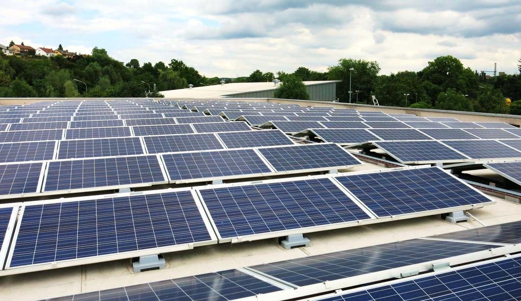
1 Exposition East West
2 CONTENTS 1 Notes on the Sika SolarMount 1 system (Exposition East West) for PV solar arrays 3 2 Setting up on site 3 3 Required Tools for mounting Sika SolarMount 1 to Sika roofing membranes 4 4 Installation of Sika SolarMount 1 (Exposition East West), step by step 4 2/16
3 1 NOTES ON THE Sika SolarMount 1 SYSTEM (EXPOSITION EAST WEST) FOR PV SOLAR ARRAYS Sika SolarMount 1 is suitable for the mounting solar systems on flat roofs with a roof pitch of up to 5 (10 with additional measures), covered with single ply roof waterproofing membranes from Sika. The system can be placed without penetration of the roof waterproofing membrane. Integrated cable channels, stackable components and the requirement for only a few tools, considerably reduces the working time on the roof. Sika SolarMount 1 can be used with or without ballasting, such as paving stones (e.g. 200 x 100 x 80 mm), according to the roof and PV system design. This system is used for fastening the frames for PV modules that are mm wide with a frame height of mm, and a weight of max. 25 kg. The racks provide an elevation of 15 from the roof plane. The Sika SolarMount 1 system consists of modular mounted units. There are variants for 2 8 modules. The distance between the mounts is determined from the static requirements arising from the relevant wind and snow loading zones. Dependent on these climatic conditions, not all of the available systems can be used. The mounts are attached to the Sarnafil roof waterproofing membrane by welding the membrane fixing flaps on the Sika SolarClick FPO or PVC systems. This ensures total compatibility between the membrane and the fixing flaps, together with their suitability for easy and secure welding. The roof s thermal insulation must be adequately designed and capable of absorbing the additional localized loadings imposed under the mounts on long term. This is also necessary to avoid effects such as ponding water, if any subsidence or permanent deformation was to occur. The complete structural design and build up, together with optimized lay out and ballasting plans are all provided by Centroplan GmbH. The cabling plans are designed by the electric planner and are made available by the PV installation customer. 2 SETTING UP ON SITE Please be especially careful with transport and interim storage of the PV modules on site and ensure a safe working environment. The Sika SolarMount 1 system is transported and delivered on heavy pallets. A crane will be required on site if the pallets have to be lifted onto the roof. Caution: Only place these pallets on sufficiently stable roofs that are capable of accommodating the load and ensure that all roof surfaces are clean when the Sika SolarMount 1 system is installed. The maximum age of an existing Sika roof membrane is 3 years, but depending on its condition. (Alternatively the PV racks can be pre assembled on installation tables up to working step 15) The information contained herein and any other advice are given in good faith based on Sika s current knowledge and experience of the products when properly stored, handled and applied under normal conditions in accordance with Sika s recommendations. The information only applies to the application(s) and product(s) expressly referred to herein. In case of changes in the parameters of the application, such as changes in substrates etc., or in case of a different application, consult Sika s Technical Service prior to using Sika products. The information contained herein does not relieve the user of the products from testing them for the intended application and purpose. All orders are accepted subject to our current terms of sale and delivery. Users must always refer to the most recent issue of the local Product Data Sheet for the product concerned, copies of which will be supplied on request. 3/16
, STEP BY STEP 1 Alignment of assembly rails Place two assembly rails together so the ridges (see arrows) are facing")
 of 0.")
4 3 REQUIRED TOOLS FOR MOUNTING Sika SolarMount 1 TO SIKA ROOFING MEMBRANES Cordless screwdriver Socket spanner 17 mm Ratchet Torque wrench Measuring tape Pencil Handheld hot air welder Pressure roller Torx Bits T25, T40 4 INSTALLATION OF Sika SolarMount 1 (EXPOSITION EAST WEST), STEP BY STEP 1 Alignment of assembly rails Place two assembly rails together so the ridges (see arrows) are facing outwards and the hammer head screw location groove faces above. Place the marks for the screws on both assembly rails using a pencil. The respective distances are shown in table 1 or in the designer s drawing. Example: For a 4.4 arrangement, the first mark is placed at a distance (b) of 0.15 m from the start of the assembly rails followed by three further marks at equal distance (a) of 1.90 m producing a distance to the other end of the mounting rail of 0.15 m. 4/16


5 2 Bestimmen der Dimensionen a), b), c) und d) Note: Rail cantilever left (b L ) und right (b R ) are different (b L ) on the left side, looking from the lower panel side (b R ) on the right side, looking from the higher panel side The distance between two systems must be considered due to the different systems Sika SolrMount 1 and the system dependent overhang of the modules above the rails. The distance under discussion here is the distance d) between the respective rail ends. The individual distances for the several Sika SolarMount 1 systems may be taken from the tables 1 and 2: System Number of Modules Number of Mounts Rail Length [m] Mount Distance a [m] Rail Cantilever b L [m] b R [m] Module Cantilever c [m] SSM1 2.4 EW SSM1 4.4 EW SSM1 4.6 EW SSM1 4.8 EW SSM1 6.6 EW SSM1 6.8 EW SSM EW SSM1 8.8 EW SSM EW SSM EW Table 1: Components and dimensions (with 60 cell modules with a long length of 1.66 m) Note: Due to thermal expansion, an additional distance of 20 mm must be added between the systems (d theroretical + 20 mm). Rail distance calculation d = c L + c R +20 mm SSM1 8.x EW SSM1 6.x EW SSM1 4.x EW SSM1 2.x EW SSM1 2.x SSM1 4.x SSM1 6.x SSM1 8.x Table 2: Rail distance d (with 20 mm distance) 5/16


6 3 Using the hammer head screw and twist protection Place the hammer head screws (M10 thread) on the marked places into the groove and twist them a little clockwise to prevent them from falling out. Place the twist protection on the hammer head screw. Now fix the twist protection in the groove. The hammer head screws are fitted with a microencapsulated adhesive and assume the function of the security nut. They can therefore only be used once. 4 Mounting of the front cap Put the front cap on the mounting racks. 6/16

.")

7 5 Montage Sika SolarClick and base plates The mounting racks need to be secured against moving and sliding during use. According to the lay out and design of the project, one single Sika SolarClick fasteners is hooked into the lateral recesses of the racks. Position see picture on the left (a) (b) (c) 5 additional base plates are mounted to the underside of the mount: 2 base plates are going to be hooked into the outermost recesses (a). The base plates shall protrude from the mount s end. The two other base plates are hooked into the third recess (b). One single base plate in the second recess opposite of the Sika SolarClick (c). Positions see picture on the left The Sika SolarClick and the base plates are available in the same material qualities as the respective Sika FPO and PVC Roofing membranes. Option: A metal clamp, perfectly matching with the shape of the Sika SolarClick, is used in case of higher temperatures or larger horizontal loads. It is going to be fixed through the mount s web by 2 screws which are delivered with the clamp. The clamps are used according to the detailed plans 7/16


8 6 Rotating the mounting rack Prepare an assembly rail with the pre assembled screws. Turn the mounts with the Sika SolarClick, base plates and the UV cap upside down and insert the hammerhead screws in the provided mounting aperture at the lower end of the mount (South). 7 Direction of the profile ridge The ridge of the module assembly rail must be facing the centre of the mount 8 Screwing the assembly rack Fit the hammer head screws with washers and nuts. 8/16


9 9 Tightening the nuts Tighten the nuts with a torque of 15 Nm. 10 Rotating the frame Once all mounting racks are firmly connected to the assembly rail, these are placed back on foot by turning them by Placing the wind deflector caps Stick the wind deflector cap onto the mount nose. In case of the East West system they serve as protection against UV radiation. 9/16
 must be facing the centre of the mount.")

10 12 Mounting the upper assembly rail Place the second rail with pre mounted hammer head screw in the slots provided. The ridge of the module assembly rail (see white arrow) must be facing the centre of the mount. 13 Inserting assembly jigs Insert assembling jigs with the width of a module (see red arrows let) on both sides between the mounting rails in order to establish the exact distance to one another, and then remove the jigs. 14 Fixing the hammer head screw Fix the washer and the nut to the hammer head screw. 10/16

 at the rear side of the first frame.")
11 15 Tightening the screw fitting Tighten the nuts with a torque of 15 Nm. 16 Aligning the roof frame Align the first frame according to the roof configuration plan. A setback of 1.5 m to the edge of the roof is to be maintained unless stated otherwise. Position the opposite frame (same construction and distances) at the rear side of the first frame. Overlap of the mounts is 0.20 m. The distance of the lower mount ends is always 2.19 m. 11/16


12 Once the opposite mount ends are aligned in the distance of 0.20 m the mounts are interconnected with two self drilling screws 6.0 x 75 mm E16. Positions of the screws see picture on the left 17 Temporary flap fixing Temporary 2 point fixing of the Sika SolarClick sections along the inner end with a handheld hot air welding gun. Special attention and care is required to avoid moving of the rack assembly during the welding process. 18 Hand welding process Hand welding of the flaps along the length of 280 mm between the arrow marks on the Sika SolarClick. The same welding process as for the relevant roofing membranes is used. Welding parameters for FPO systems are as those used for Sarnafil T; for PVC systems they should be the same as those used for Sarnafil G/S. Tools: Handheld hot air welding gun and rubber pressure roller. 12/16


13 19 Paving stone dimensions Ballasting is carried out according to the ballast plan with rectangle paving stones. E.g. 200 x 100 x 80 mm; Weight: 3.6 kg, or 200 x 100 x 600 mm; Weight: 2.8 kg. 20 Ballasting Stack the paving stones in the mounting rack. Fill up the lower part of the rack first before commencing a second layer. Maximum number of stones per layer: lower layer: 9, middle layer: 6, upper layer: 3 21 Module mounting Lay the first module onto the bases of the module assembly rails and set up the module cantilever (c) according to the previous table or the layout plan. The dimensions of the cantilever c) can be taken from table 1 (depending on the variant) or from the lay out plan. 13/16


14 22 Cable Connections Interconnect the plugs while joining the modules. 23 Laying cables Insert the bundled cables into the mounts in the mounting racks. The cables shall not allowed to swing, and the connectors may not be left on the roof as it may lead to leakage current due to ponding water. As an option the module and the string cables can be fixed additionally with special cable straps and clips. These straps and clips are not part of the SSM1 system but can be ordered from Centroplan. a) Strap for module cables b) Clip for string cables 14/16


15 a) The socket of the cable strap for the module cables is clamped into the module frame. b) The clip for the string cables is attached in the groove of the assembly rail. 24 Module mounting Insert the remaining modules with a distance of 20 mm to the adjacent modules. The junction boxes of the modules should face to the same side. 25 Positions of the module clamps Each module is fixed in place with four module clamps. The distance (e) of the clamps from the outer edge of the modules is according to the installation instruction of the PV module supplier. 15/16


16 26 Fastening module clamps Fasten the 4 module clamp screws with a torque of 2 Nm. Note: If a screw hole is stripped or otherwise faulty, screw it in again offset a few centimetres to the side. 27 Ready mounted PV generator, variant SSM1 8.8 EW 28 Disclaimer This Installation Guide is provided by Sika as a standard proposal it always remains the responsibility of the user to confirm the product suitability and the correct method for any given application. Where alternative methods or criteria to those outlined are to be used, these must first be submitted to Sika Limited for approval and agreement in writing, before the commencement of any works. Sika Limited cannot accept responsibility or liability due to any other variations or conditions SIKA LIMITED Head Office Watchmead Welwyn Garden City Hertfordshire AL7 1BQ United Kingdom Phone: Fax: Registered in England: Number Sika Services AG Roofing Speckstrasse 22 CH 8330 Pfäffikon Switzerland Sika Services AG 16/16
Rack-in-a-BoxTM INSTALLATION MANUAL
 INSTALLATION MANUAL TM 1.0 INTRODUCTION 3 2.0 PRODUCT RANGE 4 2.1 Systems 4 2.2 Accessories 4 3.0 PREPARATION FOR INSTALLATION 5 3.1 Applications 5 3.2 Tools for Installation 5 3.3 Additional Materials
Mounting System MCG 1.1 Membrane-Connected Glass. System description
 Mounting System MCG 1.1 Membrane-Connected Glass System description SUNOVA MCG 1.1 System Fields of application: Not suitable for: (please inquire for other SUNOVA systems) The SUNOVA MCG system is a lightweight
Conergy SolarFamulus II
 Conergy SolarFamulus II Installation manual www.conergy.com Table of Contents Table of Contents SolarFamulus II for universal use on flat roofs 1 Introduction 1 1.1 Short description 1 1.2 Intended use
INSTALLATION INSTRUCTIONS TRI-STAND East-West. energy for a better world. Mounting system for PV systems with east-west orientation on flat roofs
 energy for a better world INSTALLATION INSTRUCTIONS TRI-STAND East-West Mounting system for PV systems with east-west orientation on flat roofs Quick and easy installation Aerodynamically optimized No
Radiant PV-RoofTopRac System Planning and Installation With Australia AS/NZS1170.2:2011 AMDT
 Radiant PV-RoofTopRac System Planning and Installation With Australia AS/NZS1170.2:2011 AMDT 2-2012 The PV-RoofTopRac System has been developed as a universal system for roof-mounting on pitched roofs.
Mounting System MCG 3.0 Membrane-Connected Glass. System description
 Mounting System MCG 3.0 Membrane-Connected Glass System description SUNOVA MCG 3.0 System Fields of application: Not suitable for: (please inquire for other SUNOVA systems) The SUNOVA MCG 3.0 system is
Mounting System MCG 3.0 Membrane-Connected Glass. System description
 Mounting System MCG 3.0 Membrane-Connected Glass System description SUNOVA MCG 3.0 System Fields of application: Not suitable for: (please inquire for other SUNOVA systems) The SUNOVA MCG 3.0 system is
Radiant Solar Tripod Planning and Installation Guide V1.2 With Australia AS/NZS1170.2
 Radiant Solar Tripod Planning and Installation Guide V1.2 With Australia AS/NZS1170.2 The Solar Tripod System has been developed as a universal system for roof-mounting on flat roofs. The use of patented
On-roof system Tau Installation manual
 On-roof system Tau Installation manual 810-0052 Table of Contents 1 Introduction 1 1.1 Short description 1 1.2 Intended use 1 1.3 Standards and guidelines 1 1.4 About these instructions 1 Tau The innovative
Clenergy ezrack SolarRoof Code-Compliant Planning and Installation With Australia AS/NZS1170
 Clenergy ezrack SolarRoof Code-Compliant Planning and Installation With Australia AS/NZS1170 The ezrack has been developed as a universal system for roof-mounting on pitched roofs. The use of patented
Mounting systems for solar technology
 Mounting systems for solar technology ASSEMBLY INSTRUCTIONS CROSSRAIL TILT KIT 7 / 0 / 5 TILT FOR LOW-SLOPE AND STEEP-SLOPE ROOFS TABLE OF CONTENTS TABLE OF CONTENTS THE COMPANY SAFETY REGULATIONS MATERIALS
SECURE. UNIVERSAL. MOUNTING. Tilt Kit Installation Manual
 SECURE. UNIVERSAL. MOUNTING Tilt Kit Installation Manual 1.0 INTRODUCTION... 3 2.0 KITS / PRODUCT RANGE... 4 2.1 Leg Kits... 4 2.2 Rail Kits... 4 3.0 PREPARATION FOR INSTALLATION... 5 3.1 Applications...
PRR. Flush Mount Racking System. Installation Manual
 PRR Flush Mount Racking System Installation Manual Release, September 2014 Table of Contents 1. Introduction 1.1 Product Overview 1.2 About This Manual 1.3 Product Liability 1.4 Standards Compliance 1.5
GroundTrac. Installation Manual
 APPLICATION: The GroundTrac system is designed with a minimum amount of installed footings at greatly reduced labor. The system integrates with ordinary 1-1/2 schedule #40 galvanized water pipe. This ground
AluGrid100+ Mounting Instructions. AluGrid+ lower module-bearing profile. AluGrid+ fastening clamp for module-bearing profile
 AluGrid00+ Mounting Instructions Module clamp Module-bearing profile Fastening clamp Module-bearing support AluGrid+ lower module-bearing profile AluGrid+ fastening clamp for module-bearing profile End
Radiant PV-Solar Tripod System Planning and Installation With Australia AS/NZS1170.2:2011 AMDT
 Radiant PV-Solar Tripod System Planning and Installation With Australia AS/NZS1170.2:2011 AMDT 2-2012 The PV-Solar Tripod System has been developed as a universal system for tilt solar panel roof-mounting
MOUNTING SYSTEM FOR PITCHED ROOF WITH TILES. mounting system for pitched roof with tiles for solar panels in landscape setup. Rev
 MANUAL EN MOUNTING SYSTEM FOR PITCHED ROOF WITH TILES mounting system for pitched roof with tiles for solar panels in landscape setup ESDEC BV 2016 TABLE OF CONTENT 1. Introduction 1 2. General installation
ConSole. Installation instructions
 onsole Installation instructions INSRTION Product Information The onsole assembly system is the ideal solution for installing PV modules on flat roofs with pitch of up to 5 without roof penetration. Most
ValkPitched - Bitumen
 ValkPitched - itumen Installation manual Use in combination with the Project Report of the ValkPVplanner Version 01 EN Van der Valk Solar Systems Solar Mounting Systems Please note Table of contents This
MANUAL MOUNTING SYSTEM FOR BITUMEN / EPDM
 MANUAL MOUNTING SYSTEM FOR BITUMEN / EPDM EN mounting system for uninsulated pitched roof Bitumen / EPDM for solar panels portrait / landscape setup ESDEC BV 2015 TABLE OF CONTENT 1. Introduction 1 2.
Mounting systems for solar technology
 Mounting systems for solar technology ASSEMBLY INSTRUCTIONS SPEEDRAIL system GB Table of contents TABLE OF CONTENTS THE COMPANY SAFETY REGULATIONS MATERIALS REQUIRED TOOLS REQUIRED ASSEMBLY 2 3 4 5 7 8
Mounting systems for solar technology
 Mounting systems for solar technology ASSEMBLY INSTRUCTIONS S-DOME SYSTEM GB TABLE OF CONTENTS TABLE OF CONTENTS THE COMPANY SAFETY REGULATIONS MATERIALS REQUIRED TOOLS REQUIRED ASSEMBLY 2 3 4 5 8 9 Table
ValkPitched - Standing Seam
 ValkPitched - Standing Seam Installation manual Use in combination with the Project Report of the ValkPVplanner Landscape configuration: page 2 to 6 Portrait configuration: page 7 to 11 Version 01 EN Van
Mounting systems for solar technology
 Mounting systems for solar technology ASSEMBLY INSTRUCTIONS S-DOME SYSTEM GB TABLE OF CONTENTS TABLE OF CONTENTS THE COMPANY SAFETY REGULATIONS MATERIALS REQUIRED TOOLS REQUIRED ASSEMBLY 3 4 5 8 9 Table
Modular Simplicity Dero
 B I K E H AV E N Modular Simplicity The Bike Haven bridges the gap between short and long term bike parking. The simple, modular canopy design makes it easy to create the bike shelter that fits your needs.
Mounting instructions. novotegra for trapezoidal metal - roof parallel
 Mounting instructions novotegra for trapezoidal metal - roof parallel I TABLE OF CONTENTS 1 Notes... 1 2 Maintenance of the mounting system... 3 3 novotegra for trapezoidal metal - roof parallel... 3 4
Installation instructions
 Installation instructions IBC AeroFix Date: 30-Jun-2015 1 Contents 0. Introduction... 3 01. Tool list... 4 02. General information, standards and regulations... 4 03. System variants... 8 04. Technical
C.R. LAURENCE CO., INC. Intelli-Track SPS. Phase One - Installation Instructions
 Tools and Supplies: C.R. LAURENCE CO., INC. Intelli-Track SPS Phase One - Installation Instructions Ratchet Wrench with 4" Extension 9/16" Open-End Wrench (two required for suspension mounting) 9/16" Hex
Mounting instructions
 Mounting instructions novotegra for tile roofs top-fix I TABLE OF CONTENTS 1 Notes... 1 2 Maintenance of the mounting system... 3 3 novotegra for tile roofs... 3 4 System components, tools and equipment...
ON-ROOF ATTACHMENT FLAT COLLECTOR HELIOSTAR
 ON-ROOF ATTACHMENT FLAT COLLECTOR HELIOSTAR INSTALLATION INSTRUCTIONS ENERGY AND SANITARY SYSTEMS Installation requirements Generel requirements The on-roof attachment set is capable for installation of
ConSole, ConSole+ Flat-roof mounting system for PV-modules and -laminates. From visions to solutions
 ConSole, ConSole+ Flat-roof mounting system for PV-modules and -laminates From visions to solutions Customized system alternatives for fast, simple and cost-effective mounting on flat-roofs and ground
Roofing. Sarnavap 500E. Vapour control layer. Product Description. Tests. Product Data. Form. Storage
 Product Data Sheet Edition 02.2015 Identification no. 02 09 01 05 402 0 000001 Version no. 02 Sarnavap 500E Vapour control layer Product Description Sarnavap 500E is an unsupported vapour control layer
mounting systems applications overview
 mounting systems applications overview catalogue version January 2015 tritec mounting systems: overview of applications i. pitched roof: roof-top 1. Tiles, shingles and corrugated panels 1.1 TRI-STAND
ifix INSTALLATION MANUAL PV flat roof installation system Version
 ifix PV flat roof installation system INSTALLATION MANUAL Version 2012-09-06 ifix Installation Manual Version 2012-09-06 Seite 1 Table of contents Table of contents... 1 Special characteristics of ifix...
ValkPro+ Installation manual. Van der Valk Solar Systems. Use in combination with the Project Report of the ValkPVplanner. Solar Mounting Systems
 ValkPro+ Installation manual Use in combination with the Project Report of the ValkPVplanner Version 14 EN Van der Valk Solar Systems Solar Mounting Systems Please Note Table of contents This manual is
ValkPro+ East West. Installation manual. Van der Valk Solar Systems. Use in combination with the Project Report of the ValkPVplanner
 ValkPro+ East West Installation manual Use in combination with the Project Report of the ValkPVplanner Version 07 EN Van der Valk Solar Systems Solar Mounting Systems Please Note Table of contents This
Installation Guide EcoFoot5D High Density 5-Degree Ballasted Racking System Document No. ES10560
 Installation Guide Installation Guide EcoFoot5D High Density 5-Degree Ballasted Racking System Document No. ES10560 Rev 1.0, September 2017 Sales: 740-249-1877 Sales@EcolibriumSolar.com Field Support:
PRB. Flush Mount Racking System. Installation Manual
 PRB Flush Mount Racking System Installation Manual Released 5th April 2015 TABLE OF CONTENTS 1. INTRODUCTION 1.1 Product Overview 1.2 About This Manual 1.3 Product Liability 1.4 Standards Compliance 1.5
ASSEMBLY AND OPERATING MANUAL LTW SLIDE RAIL SYSTEM - Type PV
 Manufacturer: LTW Tiefbauvertriebs GmbH Holter Weg 11 D 41836 Hückelhoven-Brachelen Phone: +49 (0) 24 62 / 2009 0 Fax: +49 (0) 24 62 / 2009 15 e-mail: info@ltw-verbau.de homepage: http:\ \ www.ltw-shoring.com
ValkPro+ East West. Installation manual. Van der Valk Solar Systems. Use in combination with the Project Report of the ValkPVplanner
 ValkPro+ East West Installation manual Use in combination with the Project Report of the ValkPVplanner Version 08 EN Van der Valk Solar Systems Solar Mounting Systems Please Note Table of contents This
MOUNTING SYSTEMS APPLICATIONS OVERVIEW
 MOUNTING SYSTEMS APPLICATIONS OVERVIEW Catalogue Verion June 2013 TRITEC MOUNTING SYSTEMS: OVERVIEW OF APPLICATIONS I. Pitched Roof: Roof-Top 1. Tiles, shingles and corrugated panels 1.1 TRI-STAND on tiles
MANUAL. landscape orientation. portrait orientation. metal roof mounting system for solar panels METAL ROOF MOUNTING SYSTEM. Rev
 MANUAL METAL ROOF MOUNTING SYSTEM EN landscape orientation portrait orientation metal roof mounting system for solar panels ESDEC BV 2018 CONTENTS 1. Introduction 1 2. General installation conditions 1
Mounting systems for solar technology ASSEMBLY INSTRUCTIONS. S-Dome 2.0 System.
 Mounting systems for solar technology ASSEMBLY INSTRUCTIONS S-Dome 2.0 System www.k2-systems.com Content T Tools overview 3 T General safety information 4 T Required Materials 6 T Assembly 9 T Notes QUALITY
Schüco Mounting System MSE 210 Mounting on trapezoidal roofing
 Solar products Schüco Mounting System MSE 210 Mounting on trapezoidal roofing English Schüco Installation instructions: Installation instructions: MSE 210 trapezoidal roof Art. No. 259 713 08.2009-02 Printed
Flat roof for the loading-optimized elevation (adhesive system)
") Mounting systems Flat roof for the loading-optimized elevation (adhesive system) FLAMONT Production I Professional wholesale Adhesive mounting without roof penetration no weight easy to install low price
Mounting systems Flat roof for the loading-optimized elevation (adhesive system) FLAMONT Production I Professional wholesale Adhesive mounting without roof penetration no weight easy to install low price
PV Mounting System 2703 SERIES 200 UL GROUND MOUNT SYSTEM. SnapNrack Residential PV Mounting Systems Code Compliant Installation Manual
 PV Mounting System 2703 SERIES 200 UL GROUND MOUNT SYSTEM SnapNrack Residential PV Mounting Systems Code Compliant Installation Manual Series 200 UL Introduction Series 200 UL Introduction SnapNrack Series
MANUAL. portrait set-up. landscape set-up. ClickFit Evo mounting system for sloping roofs with roof tiles for solar panels
 MANUAL MOUNTING SYSTEMS FOR SLOPING ROOFS WITH ROOF TILES EN portrait set-up landscape set-up ClickFit Evo mounting system for sloping roofs with roof tiles for solar panels ESDEC BV 2017 CONTENTS 1. Introduction
Installation instructions
 Installation instructions IBC AeroFix Version 17.01 Date: 27-Jun-2017 1 Contents 0. Introduction...3 01. Tool list...4 02. General information, standards and regulations...4 03. System variants...8 04.
Installation manual ValkTriple EN-UK
 Van der Valk Solar Systems TRCKING ND FIXED SOLR MOUNTING SYSTEMS Installation manual ValkTriple EN-UK Version 08 EN General user instructions Solar mounting systems Congratulations on buying a Van der
Platform stair lift PLG7
 Platform stair lift PLG7 ORIGINAL-user manual Part 2: Assembly Instruction English Version 2.00 ASCENDOR GMBH Drautendorf 48 4174 Niederwaldkirchen Austria Tel.: +43 7231 40040 Fax: +43 7231 40040-590
TRAPEZOIDAL SHEET METAL RAIL LIFT/VARIO for trapezoidal sheet metal roofs
 Photovoltaic mounting systems Assembly Instructions TRAPEZOIDAL SHEET METAL RAIL LIFT/VARIO for trapezoidal sheet metal roofs 1 Table of contents 1 Introduction 1.1 Intended use 3 1.2 About the document
EASY ROOF FLAT PV FIXING SYSTEM FOR FLAT ROOF
 INS-IN02-180726 Version 1.0-24-04-18 EASY ROOF FLAT PV FIXING SYSTEM FOR FLAT ROOF For all LANDSCAPE-orientated framed modules ASSEMBLY INSTRUCTIONS Document validated by ENQUETE TECHNIQUE NOUVELLE No.
ValkFlat East West - Portrait
 ValkFlat East West - Portrait Installation manual Use in combination with the Project Report of the ValkPVplanner Version 05 EN Van der Valk Solar Systems Solar Mounting Systems Please Note Table of contents
Mounting instructions. novotegra for folded seam roof
 Mounting instructions novotegra for folded seam roof I TABLE OF CONTENTS 1 Notes... 1 2 Maintenance of the mounting system... 3 3 novotegra for folded seam roof... 3 4 System components, tools and work
AluGrid product sheet
 AluGrid The flat roof system with optimized superimposed load quick, simple and mainly tool-free mounting reduced number of components economically effi cient system structural analysis based on the latest
ValkPro+ East West. Installation manual. Van der Valk Solar Systems. Use in combination with the Project Report of the ValkPVplanner
 ValkPro+ East West Installation manual Use in combination with the Project Report of the ValkPVplanner Version 06 EN Van der Valk Solar Systems Solar Mounting Systems Please Note Table of contents This
Unitised Curtain Wall Beaded
 Unitised Curtain Wall Beaded Glazed Frame Unitised Curtain Wall Reference Brand: Sapa Building System Elegance 72 GF GENERAL DESCRIPTION Unitised curtain wall system using glazing beads for glass retention.
Installation manual ValkFlat East West - Portait
 Van der Valk Solar Systems TRCKING ND FIXED SOLR MOUNTING SYSTEMS Installation manual ValkFlat East West - Portait Use in combination with installation manual 1-2-3 PV Planner Version 01 EN General user
Modular. Lighter. Quicker.
 Modular. Lighter. Quicker. PR-1 2.0 Ballasted Rooftop Mounting System Installation Manual *Supports all 60 and 72-cell Framed Modules. Table Of Contents Table Of Contents 1. Introduction 4 1.1 Product
ASSEMBLY INSTRUCTIONS COMMERCIAL ROOF SOLUTIONS D DOME RAILLESS 2 SYSTEM. UL 2703 Listed System USA
 ASSEMBLY INSTRUCTIONS COMMERCIAL ROOF SOLUTIONS D DOME RAILLESS 2 SYSTEM UL 2703 Listed System USA TABLE OF CONTENTS TABLE OF CONTENTS SAFETY REGULATIONS MATERIALS REQUIRED BONDING AND GROUNDING FIRE RATING
Washer, Electrical Equipment Bond. WEEB Patent Pending INSTALLATION INSTRUCTIONS. For POWER-STRUT Mounting System only
 Washer, Electrical Equipment Bond WEEB Patent Pending INSTALLATION INSTRUCTIONS For POWER-STRUT Mounting System only Please read carefully before installing. Burndy LLC recommends that the sufficient details
Construction. Sika-Trocal SGmA 1.5 mm. Polymeric membrane for roof waterproofing. Product Description
 Roofing Product Data Sheet Edition 03.2009 Identification no. 02 09 01 01 124 0 150000 Version no. 03 Sika-Trocal SGmA 1.5 mm Polymeric membrane for roof waterproofing Construction Product Description
INDeX Rack Installation Notes
 INDeX Rack Installation Notes 38PJC00001SBA - Issue 8 (09/01/2002) Page 2 Contents Contents Rack Mounted Installation...3 Introduction... 3 Rack Installation Requirements... 3 Summary Details... 3 The
ROOF MOUNT KIT OWNERS MANUAL
 ROOF MOUNT KIT OWNERS MANUAL Made in the USA by: Primus Wind Power, Inc. 938 Quail St. Lakewood, CO 80215 Phone: (303) 242-5820 www.primuswindpower.com AIR is a trademark of Primus Wind Power, Inc. ROOF
Solcellspaket - Poly (4.2 kwp Jinko 265W Poly) System Plan. Created with Solar-Planit by Mikael Johansson Futura Energi AB in Simrishamn.
 System Plan. Created with Solar-Planit by Mikael Johansson Futura Energi AB in Simrishamn.") Solcellspaket - Poly (4.2 kwp Jinko 265W Poly) System Plan Created with Solar-Planit by Mikael Johansson Futura Energi AB in 272 36 Simrishamn. Project YOUR PHOTOVOLTAIC SPECIALIST Company Contact Address
Solcellspaket - Poly (4.2 kwp Jinko 265W Poly) System Plan Created with Solar-Planit by Mikael Johansson Futura Energi AB in 272 36 Simrishamn. Project YOUR PHOTOVOLTAIC SPECIALIST Company Contact Address
Modular Coldroom Installation Manual
 Modular Coldroom Installation Manual May 2005 Disclaimer: The information contained in this installation guide is provided "as is". Bromic Pty Ltd does not warrant the accuracy, adequacy or completeness
Bravo Platform Unpacking Guide
 This guide describes how to unpack the Bravo device from the shipping carton. Depending on the order, the shipment can include additional packages for the Bravo utilities, pipetting head, computer, and
ROOF MOUNT KIT OWNERS MANUAL
 ROOF MOUNT KIT OWNERS MANUAL Made in the USA by: Southwest Windpower, Inc. 1801 W. Route 66 Flagstaff, Arizona 86001 Phone: (928) 779-9463 Fax: (928) 779-1485 E-mail: info@windenergy.com Web: www.windenergy.com
USER S GUIDE for HAKITEC 750. TEMPORARY ROOF with HAKI Trak Sheeting ( Hand-Built )
") USER S GUIDE for HAKITEC 750 TEMPORARY ROOF with HAKI Trak Sheeting ( Hand-Built ) HAKI LTD 2007 INTRODUCTION Temporary roof structures are by their very nature amongst the most difficult and demanding
USER S GUIDE for HAKITEC 750 TEMPORARY ROOF with HAKI Trak Sheeting ( Hand-Built ) HAKI LTD 2007 INTRODUCTION Temporary roof structures are by their very nature amongst the most difficult and demanding
For HatiCon Solar Mounting System only
 Washer, Electrical Equipment Bond WEEB Patent Pending INSTALLATION INSTRUCTIONS For HatiCon Solar Mounting System only Please read carefully before installing. Burndy LLC. recommends that the sufficient
Roofing. Sika-Trocal SG 1.5 mm. Polymeric membrane for roof waterproofing. Product Description
 Roofing Product Data Sheet Edition 02.2015 Identification no. 02 09 01 01 122 0 150000 Version no. 02 Sika-Trocal SG 1.5 mm Polymeric membrane for roof waterproofing Product Description Sika-Trocal SG
HELIOSTAR 252, 218 VERTICAL, FREE INSTALLATION
 HELIOSTAR 252, 218 VERTICAL, FREE INSTALLATION INSTRUCTION MANUAL ENERGY AND SANITARY SYSTEMS Installation requirements General requirements The free-standing installation set is to be used or installing
Mounting systems for solar technology ASSEMBLY INSTRUCTIONS. S-Dome System.
 Mounting systems for solar technology ASSEMBLY INSTRUCTIONS S-Dome System www.k2-systems.com Content TTTools overview 3 TTGeneral safety information 4 TTRequired Materials 6 TTAssembly 9 TTNotes 17 QUALITY
Installation manual ValkPro+ East West
 Van der Valk Solar Systems TRCKING ND FIXED SOLR MOUNTING SYSTEMS Installation manual ValkPro+ East West Use in combination with the installation manual of the 1-2-3 PV Planner Version 05 EN General user
Installation manual ValkPro+ East West
 Van der Valk Solar Systems TRCKING ND FIXED SOLR MOUNTING SYSTEMS Installation manual ValkPro+ East West Use in combination with the installation manual of the 1-2-3 PV Planner Version 04 EN General user
Infix ProLine Installation manual
 Infix ProLine Installation manual 80-0007 Table of contents Introduction. Overview. Intended use. Standards and technical directives.4 About this manual Theta Only the sun gets in Safety. Basic safety
AluGrid100+ mounting instructions
 AluGrid00+ mounting instructions Module clamp Required tools: Measuring tape AluGrid pliers Screw-in tool Knife (for support rubber) Power screwdriver with 8 mm bit AluGrid+ lower module-bearing profile
ValkDouble. Installation manual. Van der Valk Solar Systems. Solar Mounting Systems. Version 07 EN
 ValkDouble Installation manual Version 07 EN Van der Valk Solar Systems Solar Mounting Systems Please note This manual is not project specific. This manual is not legally binding. No right may be derived
Axiom. SURFACE MOUNTED ARRAY Patient Headwall. Installation Guidelines. Installation Instructions.
 Axiom www.hsiheadwalls.com SURFACE MOUNTED ARRAY Patient Headwall Installation Instructions Installation Guidelines Tel: 925.427.7800 Fax: 925.427.0800 support@hsiheadwalls.com Hospital Systems Inc. 750
a-si/μcsi Tandem Module Installation Manual Macsun Solar Energy Technology Co., Limited Applied to MS-SDXX
 a-si/μcsi Tandem Module Installation Manual Macsun Solar Energy Technology Co., Limited 2014.1.20 Applied to MS-SDXX 1. 2. 3. 4. 5. CONTENT PURPOSE... 2 WARNING... 2 SCOPE... 2 RESPONSIBILITY... 2 INSTALLATION...
Installation Guide EcoFoot2+ 10-Degree Ballasted Racking System Document No. ECO-002_850. Rev 1.6, January 2018
 Installation Guide EcoFoot2+ 10-Degree Ballasted Racking System Document No. ECO-002_850 Rev 1.6, January 2018 Sales: 740-249-1877 Sales@EcolibriumSolar.com Field Support: 866-488-6794 FieldSupport@EcolibriumSolar.com
STRAIL level crossing systems & STRAILastic track damping systems
 pontistrail - installation instructions Subject to technical changes / February 2010 STRAIL level crossing systems & STRAILastic track damping systems Gummiwerk KRAIBURG Elastik GmbH / D-84529 Tittmoning
PRU-D INSTALLATION MANUAL MONO-LEG SYSTEM. PRU-D / Portrait - Revision B July 31 st, 2017 Polar Racking Inc.
 PRU-D INSTLLTION MNUL MONO-LEG SYSTEM Table of Contents Table of Contents... 2 1. Safety... 3 Basic Safety Considerations... 3 Warnings and Symbols... 3 Responsibilities of the Installer... 3 Responsibilities
installation instructions English
 www.creotecc.com installation instructions English Safety instructions 04 General notes 07 Material & tool requirements 08 System overview 10 installation of CREODUR 11 Maintenance 22 04 INTENDED USE
ValkQuattro. Installation manual. Van der Valk Solar Systems. Solar Mounting Systems. Version 07 EN
 ValkQuattro Installation manual Version 07 EN Van der Valk Solar Systems Solar Mounting Systems Please note This manual is not project specific. This manual is not legally binding. No right may be derived
Installation manual ValkPro+
 Van der Valk Solar Systems TRCKING ND FIXED SOLR MOUNTING SYSTEMS Installation manual ValkPro+ Use in combination with the installation manual of the 1-2-3 PV Planner Version 10 EN General user instructions
Roofing. Sarnacol Adhesive for Insulation Boards. Product Description. Product Data. Polyurethane-based humidity-hardening one-pack adhesive
 Roofing Product Data Sheet Edition 06.2016 Identification no: 020945072000000006 Version no. 01 Sarnacol 2162 Adhesive for Insulation Boards Roofing Product Description Uses Characteristics / Advantages
Curtain Wall Stick System (Capped)
") Curtain Wall Stick System (Capped) Stick Construction Capped Curtain Wall Reference Brand: Sapa Building System Elegance 52 ST GENERAL DESCRIPTION Grid based thermally insulated curtain wall system with
Curtain Wall Stick System (Capped) Stick Construction Capped Curtain Wall Reference Brand: Sapa Building System Elegance 52 ST GENERAL DESCRIPTION Grid based thermally insulated curtain wall system with
SARNAWELD - INDUCTION WELDING FASTENING
 - INDUCTION WELDING FASTENING IN COOPERATION WITH 1 INDUCTION WELDING FASTENING SYSTEM The new Sarnaweld system is a revolutionary, induction welding fastening system for flat roofs. Sarnaweld offers totally
INSTALLATION INSTRUCTIONS ENGLISH
 INSTALLATION INSTRUCTIONS ENGLISH Safety instructions 04 General notes 07 Material & tool requirements 08 System overview 10 installation of CREODUR 11 Maintenance 22 04 INTENDED USE Creotecc mounting
Mounting systems for solar technology ASSEMBLY INSTRUCTIONS. D-Dome 2.0 System.
 Mounting systems for solar technology ASSEMBLY INSTRUCTIONS D-Dome 2.0 System www.k2-systems.com Content TTTools overview 3 TTGeneral safety information 4 TTRequired Materials 6 TTAssembly 9 TTNotes 16
ASSEMBLY INSTRUCTIONS RESIDENTIAL SOLUTION CROSSRAIL GROUND MOUNT SYSTEM USA
 ASSEMBLY INSTRUCTIONS RESIDENTIAL SOLUTION CROSSRAIL GROUND MOUNT SYSTEM USA TABLE OF CONTENTS TABLE OF CONTENTS SAFETY REGULATIONS MATERIALS REQUIRED ASSEMBLY ENGINEERING DRAWINGS TERMS AND CONDITIONS
Exterior System installation instructions
 Exterior System installation instructions 11/20/14 WPS ES-400 & 500 INSTALLATION INSTRUCTION. The WPS ES-400 & 500 systems Façade panels are designed for use as an external wall cladding in conjunction
ASSEMBLY AND OPERATING MANUAL LTW EG CORNER - MANHOLE
 Manufacturer: LTW Tiefbauvertriebs GmbH Holter Weg 11 D 41836 Hückelhoven-Brachelen Phone: +49 (0) 24 62 / 2009 0 Fax: +49 (0) 24 62 / 2009 15 e-mail: info@ltw-verbau.de homepage: http:\ \ www.ltw-shoring.com
GROUND MOUNT INSTALLATION MANUAL
 GROUND MOUNT INSTALLATION MANUAL Contents DISCLAIMER 1 CHECKLIST 2 1. ERECT BASe 3 2. CONNECT PIPES 3 3. PLACE RAILS 4 4. SECURE LUGS 4 5. CLAMP MODULES 5 DIAGONAL BRACES (OPTIONAL) 6 UNDER CLAMPS (OPTIONAL)
V 2.0 ASSEMBLY GUIDE. TS Platform Scale Series 2
 V 2.0 ASSEMBLY GUIDE Series 2 TABLE OF CONTENTS OVERVIEW General Specifications...1 Cautions and Disclaimers...1 Contents of Kit...1 Tools Required For Assembly...2 Time Required to Assemble...2 ASSEMBLING
6x5. Assembly Manual CAUTION. Sharp Edges PATENTS ARE PENDING. Building Dimensions. Approximate Size. Storage Area. Interior Dimensions
 Assembly Manual 6x5 PATENTS ARE PENDING Building Dimensions Approximate Size Storage Area Exterior Dimensions Interior Dimensions Roof Edge to Roof Edge Wall to Wall Sq. Ft. Cu. Ft. Width Depth Height
Inigo Console Table INSTALLATION INSTRUCTIONS P74300, P A Page 1 of 5
 P74300, P74301 Page 1 of 5 THANK YOU FOR CHOOSING KALLISTA We appreciate your commitment to Kallista quality products. Please take a moment to review this manual before you install your Kallista product.
INSTALLATION GUIDE DUOFUSE DECKING
 INSTALLATION GUIDE DUOFUSE DECKING We recommend reading through the entire installation instructions before starting, and check the website for the latest installation instructions. Plastivan disclaims
According German Standard DIN part 1. Standard range of PVC-P based flexible waterstops for movement (expansion) and construction joint sealing
 and construction joint sealing") Product Data Sheet Edition 08/08/2014 Identification no: 02 07 03 50 330 0 000001 Sika Waterbar PVC-P Sika Waterbar PVC-P According German Standard DIN 18541 part 1 Standard range of PVC-P based flexible
Product Data Sheet Edition 08/08/2014 Identification no: 02 07 03 50 330 0 000001 Sika Waterbar PVC-P Sika Waterbar PVC-P According German Standard DIN 18541 part 1 Standard range of PVC-P based flexible