MSE WALLS CASE STUDIES. by John G. Delphia, P.E. TxDOT Bridge Division Geotechnical Branch
|
|
|
- Constance Richards
- 6 years ago
- Views:
Transcription
1 MSE WALLS CASE STUDIES by John G. Delphia, P.E. TxDOT Bridge Division Geotechnical Branch


2 COMMON RETAINING WALL TYPES CONCRETE BLOCK MSE TEMPORARY EARTH SPREAD FOOTING Gabions Drilled Shaft Soil Nail Tiedback Hybrid Walls MSE/Soil Nail RETAINING WALL SELECTION FILL SITUATIONS CUT SITUATIONS CUT/FILL SITUATIONS - MSE - CONCRETE BLOCK - SPREAD FOOTING - TEMPORARY EARTH - GABION - DRILLED SHAFT - TIEDBACK - SOIL NAIL - MSE WITH SHORING - SPREAD FOOTING WITH SHORING - DRILLED SHAFT - MSE WITH SHORING - SPREAD FOOTING WITH SHORING - HYBRID SOIL NAIL/MSE
3 Wall Usage by TxDOT (August 2010 through September 2011) Wall Type Area (ft 2 ) % MSE 3,196, Concrete block (no r/f) 47,791 1 Cantilever drilled shaft 72,286 2 Soil Nailed 146,793 3 Rock Nailed 197,216 5 Tied-back 161,827 4 Spread footing 505, Other 22,389 1

4 TxDOT has had relatively few problems.
5 MSE WALL ISSUES DESIGN - Global Stability - Strength Conditions - Presence of Water - Placement of Walls on Slopes CONSTRUCTION - Embankment/Backfill Placement - Foundation Soil Preparation - Obstructions - Damaged Reinforcements - Connections - Backfill Properties
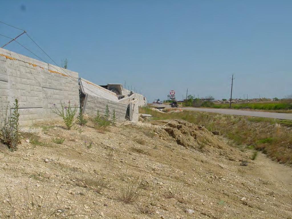
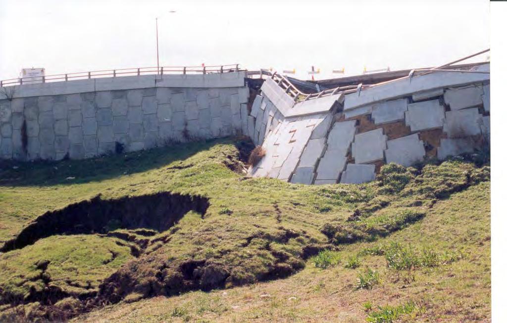
6 DESIGN - Global Stability - Strength Conditions - Presence of Water - Placement of Walls on Slopes
7 GLOBAL STABILITY MSE Backfill Random Fill MSE Backfill Random Fill Foundation Soil Foundation Soil Need to determine: -geometry -short term strength = undrained shear strength -long term strength = drained shear strength -water table

8
9

10 MSE WALL STANDARD Design Parameters: Design of retaining walls shall be based on the following design parameters unless stated elsewhere in the plans: Random Backfill/Foundation unit weight = 125 pcf Phi = 30 0 C = 0 psf THE STRENGTH PARAMETERS SELECTED BY THE DESIGNER FOR THE GLOBAL STABILITY ANALYSIS SHOULD BE STATED IN THE PLANS IF THEY ARE DIFFERENT THEN STATED ABOVE.
11 IMPORTANCE OF ACCURATE STRENGTH PARAMETERS Active Earth Pressure Ka = Tan 2 (45 Φr/2) Φr = Random Fill Friction Angle Foundation Friction Angle Φf = Foundation Soil Friction Angle Sliding and Overturning depend upon these values.
12 Overall (global) stability and external stability (sliding, overturning, eccentricity) of every wall must be evaluated by the engineer who selects the wall (especially those on slopes). Short-term and Long-term conditions must be evaluated. Designers need to list in the plans the random fill and foundation soil strength parameters if they are different then those listed on the standard sheet. The presence of water and its effects are important. Carefully evaluate placing a wall on a slope. May be false economy.
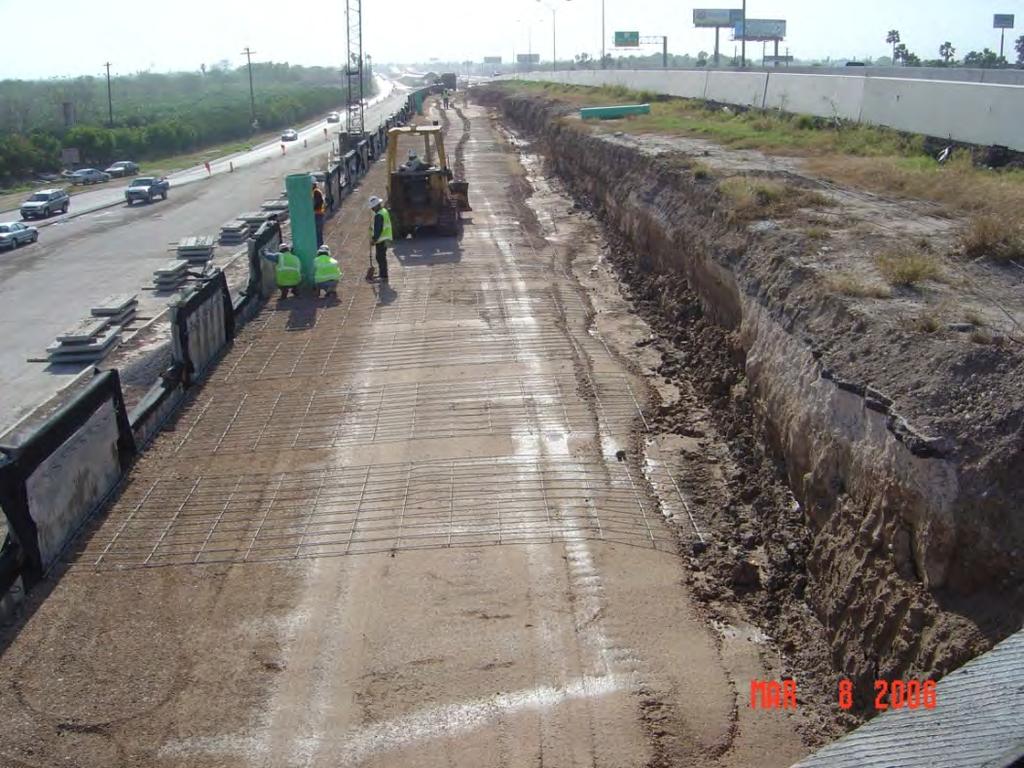
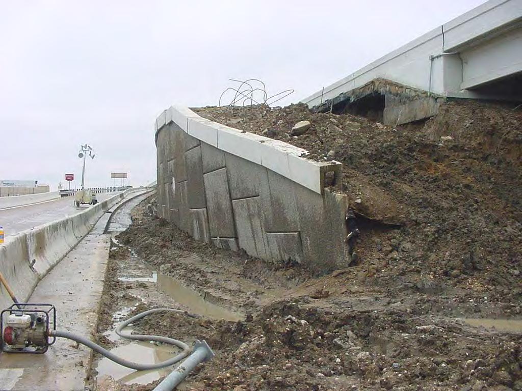
13 CONSTRUCTION - Embankment/Backfill Placement
14 ITEM 423 Place the select and embankment backfill to the same elevation where possible, and operate the compaction equipment over the interface. Do not complete the embankment prior to construction of the retaining wall.

15
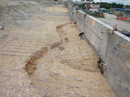
16 ITEM 423 Prevent surface water or rainwater from damaging the retaining walls during construction. Shape the backfill to prevent water from ponding or flowing on the backfill or against the wall face. Remove and replace any portion of the retaining wall damaged or moved out of tolerance by erosion, sloughing, or saturation of the retaining wall or embankment backfill.
17

18 Item 423 Place drilled shafts and piling located within the MSE volume prior to construction of the wall. How does one compact the backfill around the abutment? How does one compact against the embankment soil?
19 Inspectors need to follow and enforce the specifications. The behavior of the wall is highly dependent upon the construction process

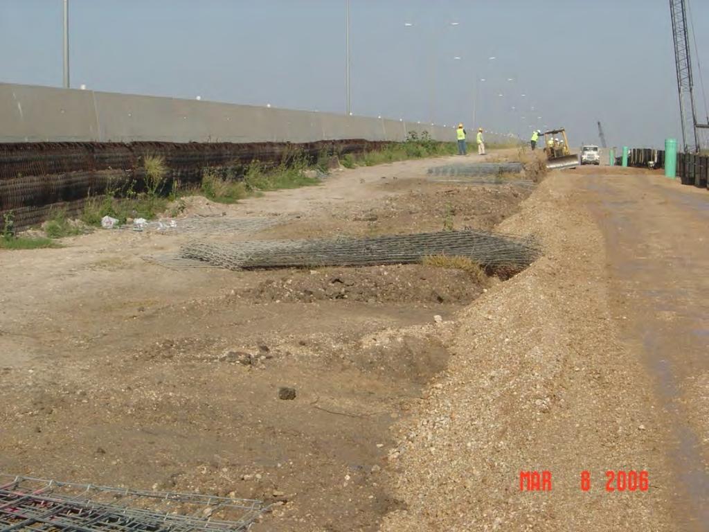
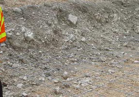
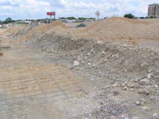
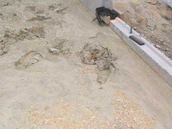
20 Foundation Preparation Item 423 Compact the foundation with a smooth-wheel vibratory roller or other approved roller. Remove and replace unsuitable foundation soils. Perform proof rolling on retaining wall foundation area to identify any loose, soft or unsuitable materials in accordance with Item 216. Material not meeting a maximum rut depth of 1 in per pass of pneumatic tired roller should continue to be rolled or removed and replaced with suitable material.


21 POOR PREPARATION OF RETAINING WALL FOUNDATION SOILS LEAD TO SETTLEMENT OF THE WALL
22 CONSTRUCTION - Obstructions Drilled Shafts Drainage Features

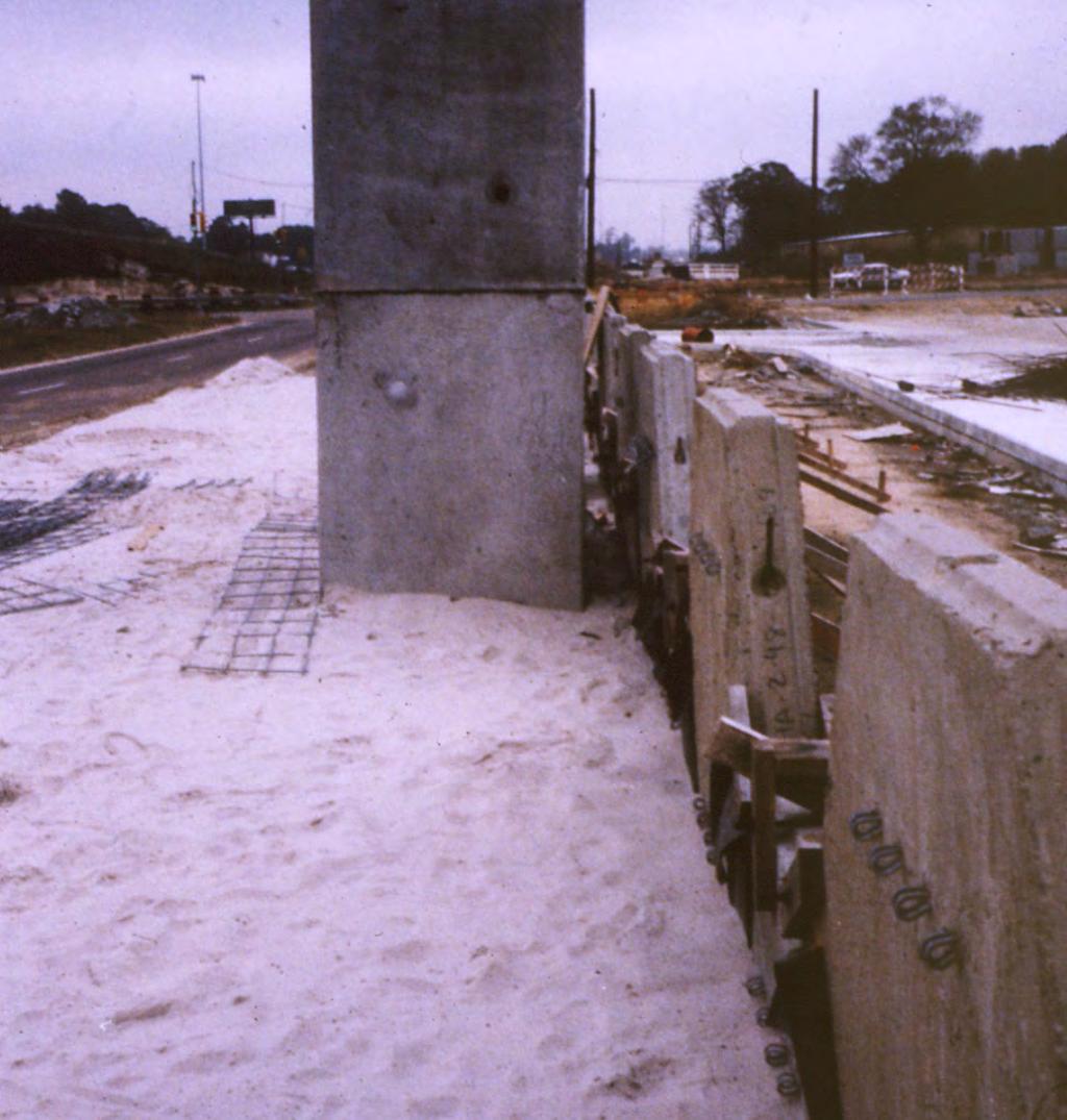
23 Wall Construction Issues Drilled Shaft Obstructions Need a minimum of 3 from back of wall to face of abutment cap to facilitate wall construction
24

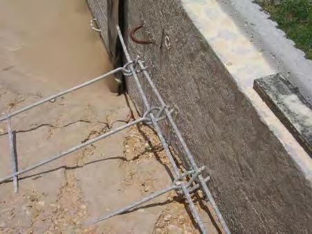
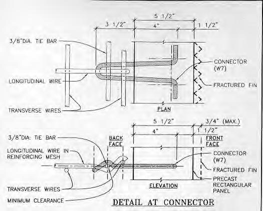
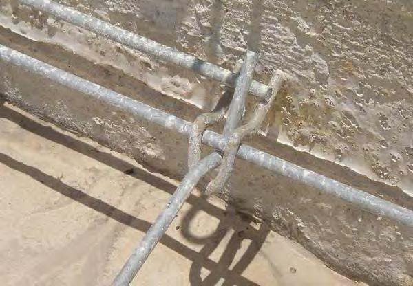
25 Incomplete connection with locking rod. Panel showing movement Soil reinforcing mat is rotated by wedging to the back of panel. This prevents bearing of the grid to the locking rod allowing potential of movement on the right side of the panel.

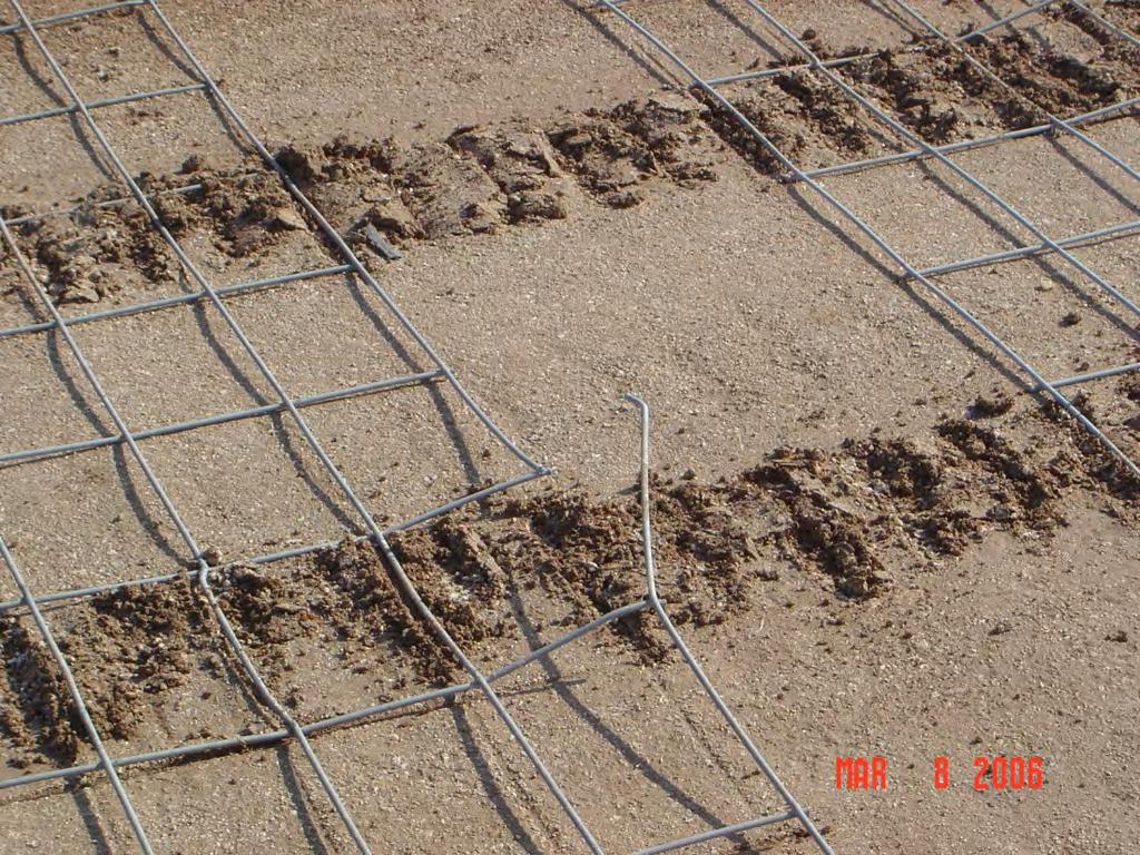
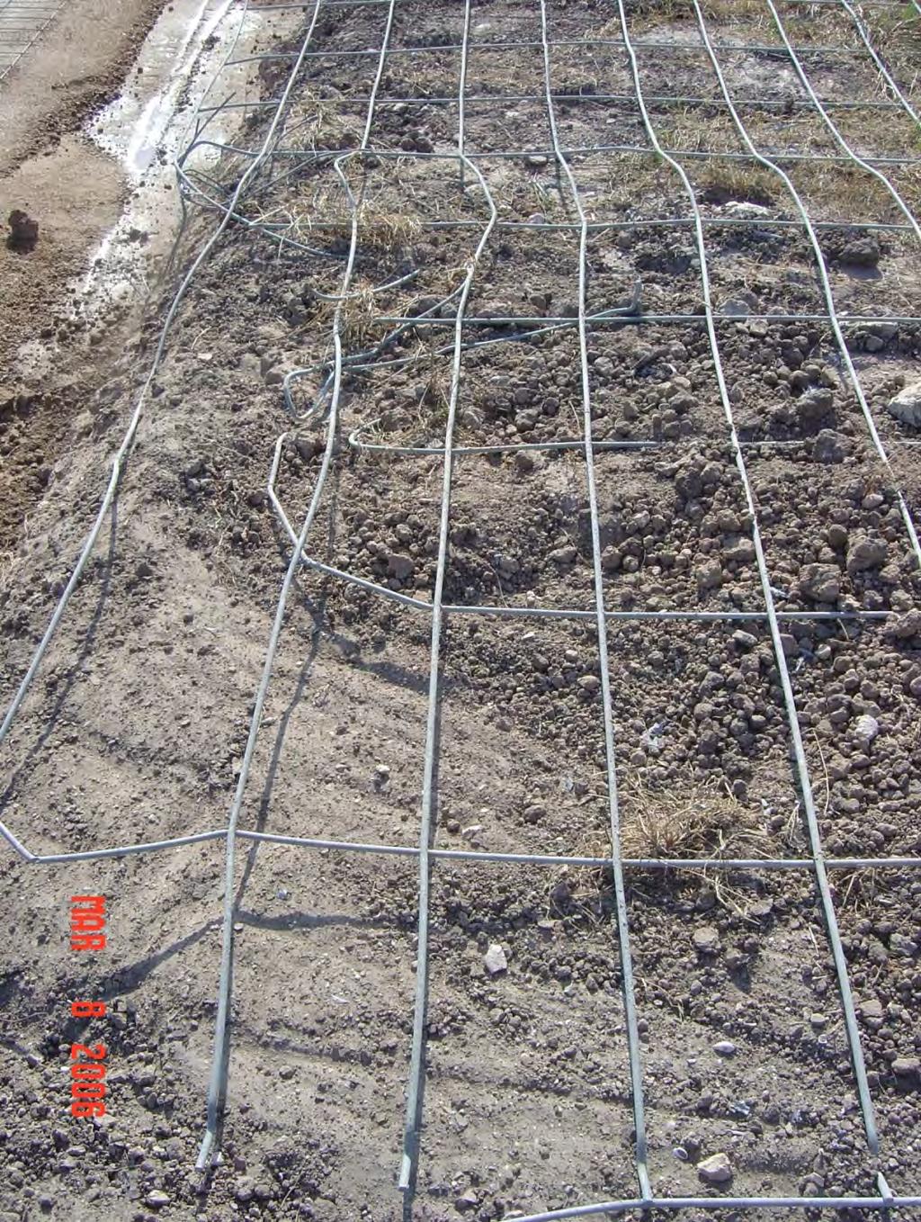
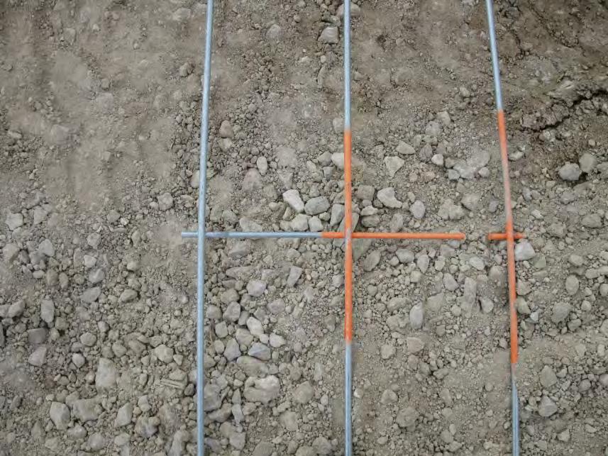
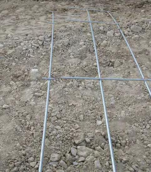
26 Earth reinforcement is cut and splayed. Transverse wires have been completely removed from the longitudinal wires in the splayed zone. This renders the earth reinforcement ineffective in pull out.
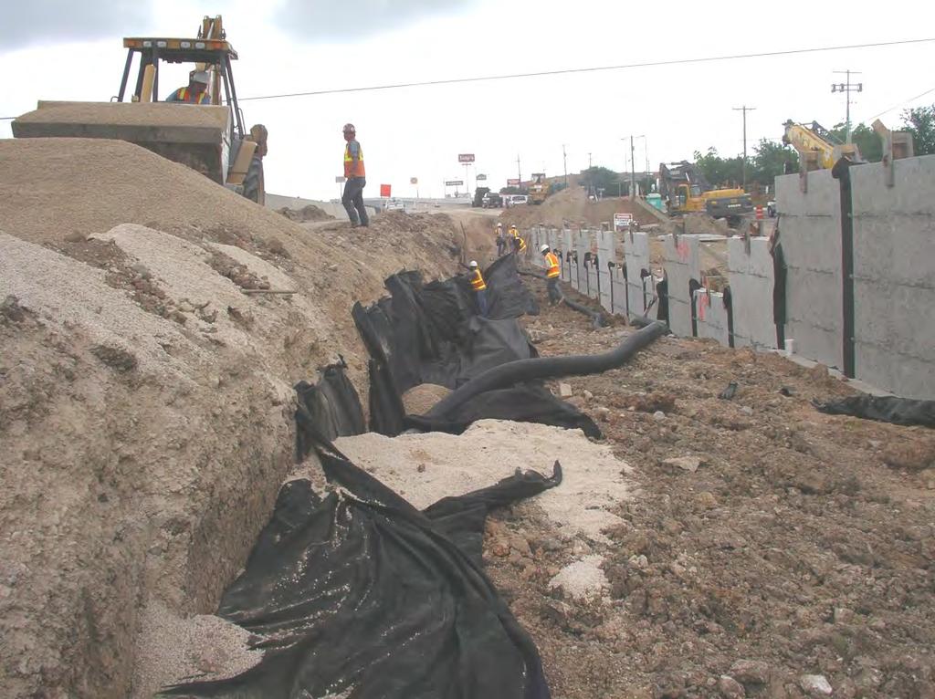
27 Obstructions - Drainage


28 Storm Sewer Parallel to Wall Omitted Reinforcement = Panel Movement >> Unstable Wall Lateral with Vertical Stand Pipe Differential Movement in Backfill = Pipe Separation >> Unstable Wall Differential Movement in Backfill = Pipe Separation >> Unstable Wall
29 Vertical Stand Pipe
30 Won t the pipe under the leveling pad separate? NO

31 ?


32 Details for obstructions need to be: - consistent with the design in regions without obstructions - clear and should be easily constructed
33 TxDOT developed a shallow inlet standard 1-10 in depth
34 When inlets have to be placed behind the wall TxDOT uses the vertical stand pipe option and the new shallow inlet standard Details for obstructions need to be: - consistent with the design in regions without obstructions - clear and should be easily constructed Inspection is critical to ensuring the obstruction detail is properly executed in the field
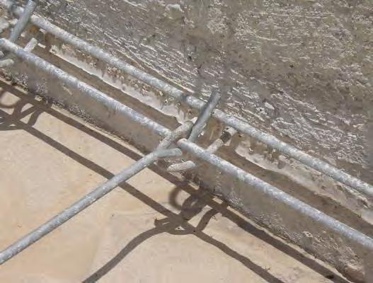
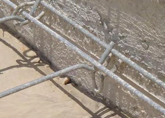
35 CONSTRUCTION - Damaged Reinforcements
36
37
38
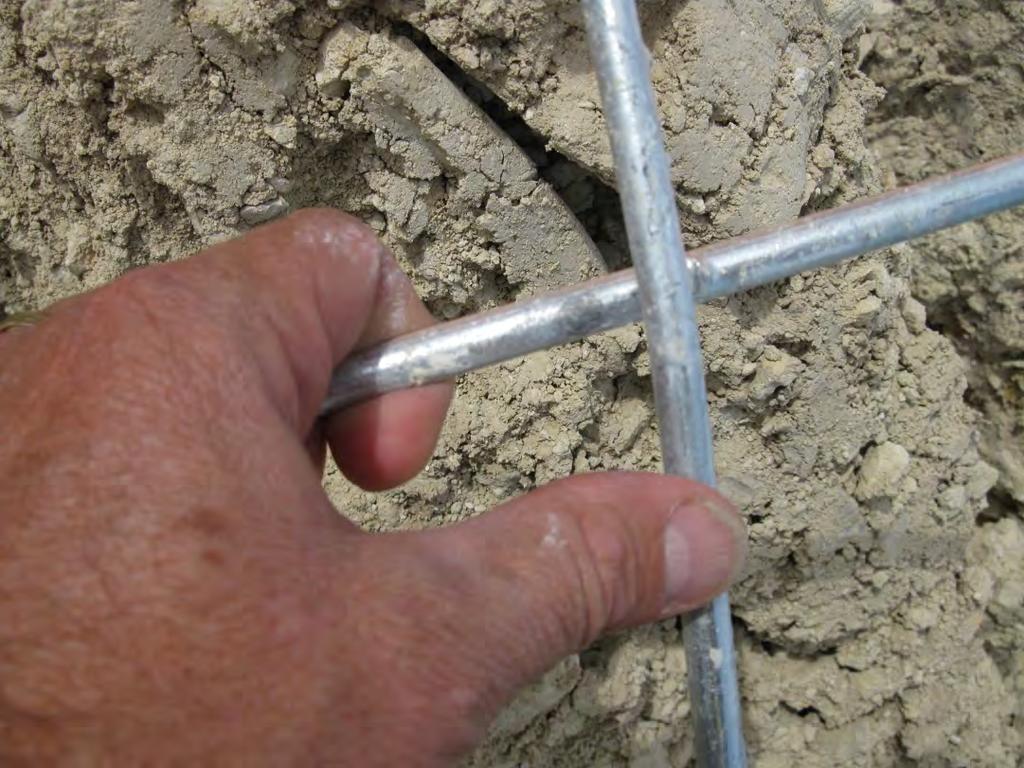
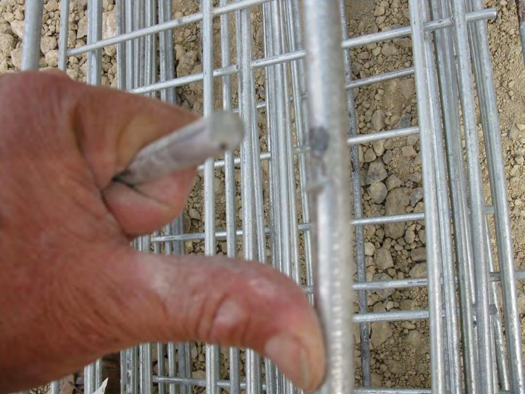
39 Inspectors need to inspect the reinforcements for potential damage Damaged reinforcements need to be rejected and removed from the job
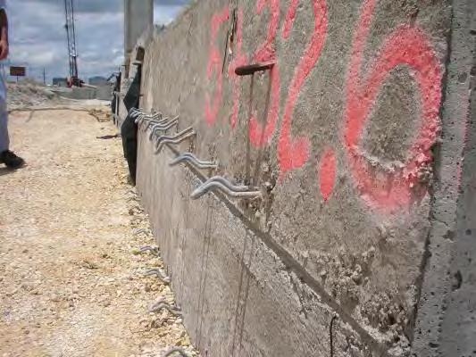
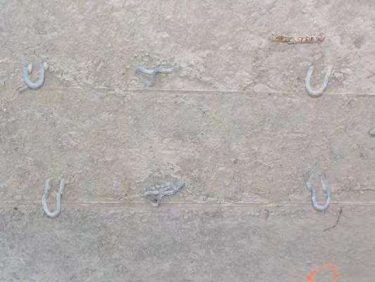
40 CONSTRUCTION - Connections
41
42
43 Inspectors need to be on the lookout for damaged connectors and to make sure the reinforcements are properly connected to the panels TxDOT instituted the following: Panels should be rejected if: - 25% of the total panel anchorage are damaged - Connectors are bent more than 30 degrees from perpendicular to the panel Galvanization on a straightened connector should be restored to yield a 75 year design life
44 MSE WALL ISSUES MATERIAL - Backfill Properties
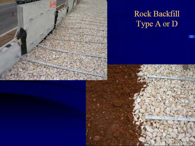
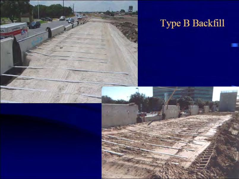
45 2004 Backfill Specifications TYPE SIEVE SIZE PERCENT PASSING 3 in. 100 A ½ in No in. 100 B No C D No in. 100 No in /8 in For Types A, B, and C if > 15% passes a No. 4 sieve the backfill is considered to be rock backfill. Resistivity > 3000 ohms-cm Chloride <100 ppm ph from 5 to 10 Sulfate <200 ppm
46
47
48
49

50 Backfill should be tested prior to construction and then tested using the above schedule, unless the backfill changes and then it should be tested again to make sure it meets the specifications


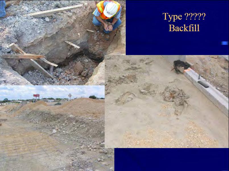
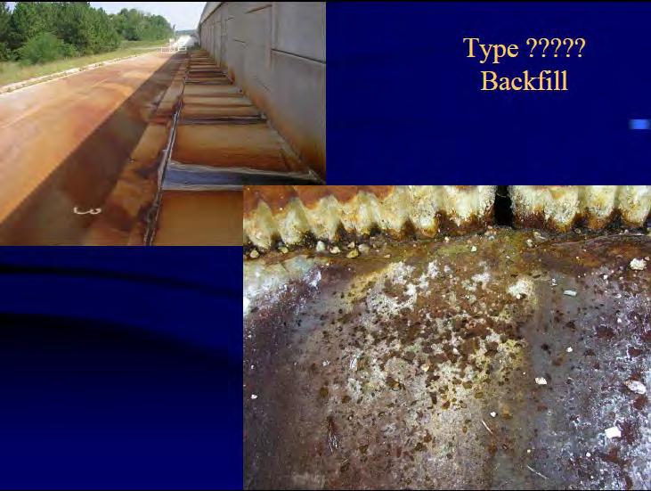
51 Improper backfill causes potential for: - reduced pullout - water pressure buildup - wall failure
52 Gradation of the backfill significantly affects the performance of MSE walls. Backfill should be tested from an onsite stockpile and should use a wet sieve method to determine percentage of fines. Backfill should not break down under compaction or in the presence of water. Backfills with significant fine material: have lower drained shear strength larger lateral earth pressures retains water and allows pore pressures to build up can undergo large settlements.
53 CONCLUSIONS TxDOT has used MSE Walls since the 80 s and they are the most utilized wall type. In spite of the high use of MSE Walls, TxDOT has had relatively few issues with them. The issues found can be categorized into two different types: design, and construction/inspection. TxDOT has reviewed and analyzed all the issues to better understand why they occurred and what caused them. The lessons learned from the issues observed have helped TxDOT to formulate corrective actions (workshops, presentations, updated specifications, etc.) to help prevent future problems. Treat the construction of the walls as a structure (bridge) not as an embankment
54 QUESTIONS?
Best Practices for Design and Construction of MSE Walls
 Best Practices for Design and Construction Robert A. Gladstone, P.E. Executive Director Association for Mechanically Stabilized Earth Geotechnical Consultant Workshop Ohio Department of Transportation
MagnumStone Specifications Gravity
 MagnumStone Specifications Gravity SPECIFICATION FOR MAGNUMSTONE GRAVITY MECHANICALLY STABILIZED EARTH SYSTEM PART 1: GENERAL.01Description The work consists of supplying and installing all aspects of
STATE OF OHIO DEPARTMENT OF TRANSPORTATION SUPPLEMENTAL SPECIFICATION 867 TEMPORARY WIRE FACED MECHANICALLY STABILIZED EARTH WALL.
 STATE OF OHIO DEPARTMENT OF TRANSPORTATION SUPPLEMENTAL SPECIFICATION 867 TEMPORARY WIRE FACED MECHANICALLY STABILIZED EARTH WALL April 15, 2016 867.01 Description 867.02 Definitions 867.03 Materials 867.04
Reinforced Soil Slopes (RSS)
") Supplemental Technical Specification for Reinforced Soil Slopes (RSS) SCDOT Designation: SC-M-206-1 (4/16) 1.0 DESCRIPTION 1.1 Construct a reinforced soil slope in accordance with these specifications,
Supplemental Technical Specification for Reinforced Soil Slopes (RSS) SCDOT Designation: SC-M-206-1 (4/16) 1.0 DESCRIPTION 1.1 Construct a reinforced soil slope in accordance with these specifications,
CHAPTER 11: WALLS.
 CHAPTER 11: WALLS MODULAR BLOCK WALL (DRY CAST) Rather than being pre-approved as systems, the components of Modular block walls (dry cast) are pre-approved separately. The approved MBW components are
ODOT Design & Construction Requirements for MSE Walls
 ODOT Design & Construction Requirements for MSE Walls Peter Narsavage, P.E. Foundation Engineering Coordinator Ohio Department of Transportation Office of Structural Engineering 2006 Ohio Transportation
DESIGNING AND CONSTRUCTION OF T-WALL RETAINING WALL SYSTEM
 Istanbul Bridge Conference August 11-13, 2014 Istanbul, Turkey DESIGNING AND CONSTRUCTION OF T-WALL RETAINING WALL SYSTEM T. C. NEEL and K.BOZKURT ABSTRACT This work shall consist of the design, manufacture
Excavate drilled shafts in accordance with Item 416, Drilled Shaft Foundations.
 Item Excavation and Backfill for Structures 1. DESCRIPTION 2. MATERIALS Excavate for placement and construction of structures and backfill structures. Cut and restore pavement. Use materials that meet
Strengthened Soil Wall Construction Manual
 Strengthened Soil Wall Construction Manual This information has been prepared by Shaw Technologies, Inc. as an aid in constructing their Strengthened Soil Wall system. Final determination of the suitability
twenty four foundations and retaining walls Foundation Structural vs. Foundation Design Structural vs. Foundation Design
 ALIED ARCHITECTURAL STRUCTURES: STRUCTURAL ANALYSIS AND SYSTEMS DR. ANNE NICHOLS SRING 2018 lecture twenty four Foundation the engineered interface between the earth and the structure it supports that
SPECIFICATION FOR MAGNUMSTONE GEOGRID REINFORCED Mechanically Stabilized Earth (MSE) SYSTEM
 SYSTEM") MagnumStone Specifications Geogrid Reinforced SPECIFICATION FOR MAGNUMSTONE GEOGRID REINFORCED Mechanically Stabilized Earth (MSE) SYSTEM PART 1: GENERAL 1.01 Description The work consists of supplying
MagnumStone Specifications Geogrid Reinforced SPECIFICATION FOR MAGNUMSTONE GEOGRID REINFORCED Mechanically Stabilized Earth (MSE) SYSTEM PART 1: GENERAL 1.01 Description The work consists of supplying
twenty six concrete construction: foundation design ELEMENTS OF ARCHITECTURAL STRUCTURES: FORM, BEHAVIOR, AND DESIGN DR. ANNE NICHOLS SPRING 2013
 ELEMENTS OF ARCHITECTURAL STRUCTURES: FORM, BEHAVIOR, AND DESIGN DR. ANNE NICHOLS SPRING 2013 lecture twenty six concrete construction: www.tamu.edu foundation design Foundations 1 Foundation the engineered
Description. This work shall consist of furnishing materials and placement of modular block wall constructed in accordance with
 MODULAR CONCRETE BLOCK RETAINING WALL WITH GROUND REINFORCING The Standard Specifications are revised as follows: 732-R-310r 1of 11 Rev. 12-03-03 SECTION 105, AFTER LINE 48, INSERT AS FOLLOWS: When constructing
FLORIDA DEPARTMENT OF TRANSPORTATION
 TEMPORARY WIREWALL MSE RETAINING WALLS SAMPLE DETAIL DRAWINGS INDEX DESCRIPTION 1 TITLE 2 GENERAL NOTES 3-4 TEMPORARY WIREWALL DETAILS 5-6 TRI-WEB TEMPORARY WALL DETAILS 7 TYPICAL TEMPORARY WIREWALL 8
GEOSYTHETIC SLOPE SPEC-V0704rev.doc STANDARD SPECIAL PROVISION FOR GEOSYNTHETIC REINFORCED SLOPE CONSTRUCTION
 GEOSYTHETIC SLOPE SPEC-V0704rev.doc STANDARD SPECIAL PROVISION FOR GEOSYNTHETIC REINFORCED SLOPE CONSTRUCTION I. DESCRIPTION - This work consists of furnishing the required materials and construction of
SPECIFICATION FOR CORNERSTONE GEOGRID REINFORCED SEGMENTAL RETAINING WALL SYSTEM
 CornerStone Specifications Geogrid Reinforced SPECIFICATION FOR CORNERSTONE GEOGRID REINFORCED SEGMENTAL RETAINING WALL SYSTEM PART 1: GENERAL 1.01 Description The work consists of supplying and installing
twenty seven concrete construction: foundation design Foundation Structural vs. Foundation Design Structural vs. Foundation Design
 ARCHITECTURAL STRUCTURES: FORM, BEHAVIOR, AND DESIGN DR. ANNE NICHOLS SRING 2017 lecture twenty seven Foundation the engineered interface between the earth and the structure it supports that transmits
DIVISION 4100 SITEWORK
 DIVISION 4100 SITEWORK SECTION 4115 EARTHWORK PART 1 - GENERAL 1.01 SCOPE This section covers the grading and compaction of excavations, embankments, structural foundations, and planted areas. 1.02 REFERENCES
Geotechnical Engineering Software GEO5
 Geotechnical Engineering Software GEO5 GEO5 software suite is designed to solve various geotechnical problems. The easy -to -use suite consists of individual programs with an unified and user-friendly
SPECIFICATIONS FOR PRECAST MODULAR BLOCK RETAINING WALL SYSTEM (revised 5/8/7)
") Page 1 of 7 STONE STRONG SYSTEMS SPECIFICATIONS FOR PRECAST MODULAR BLOCK RETAINING WALL SYSTEM (revised 5/8/7) PART 1: GENERAL 1.01 Description A. Work includes furnishing and installing precast modular
Page 1 of 7 STONE STRONG SYSTEMS SPECIFICATIONS FOR PRECAST MODULAR BLOCK RETAINING WALL SYSTEM (revised 5/8/7) PART 1: GENERAL 1.01 Description A. Work includes furnishing and installing precast modular
SECTION MECHANICALLY STABILIZED EARTH RETAINING WALLS
 SECTION 13100 MECHANICALLY STABILIZED EARTH RETAINING WALLS PART 1 -- GENERAL 1.01 THE REQUIREMENT A. Includes all labor, material, equipment, testing and submittals required to design and complete construction
DIVISION: EXTERIOR IMPROVEMENTS SECTION: RETAINING WALLS SECTION: SEGMENTAL RETAINING WALLS REPORT HOLDER:
 0 Most Widely Accepted and Trusted ICC-ES Evaluation Report ICC-ES 000 (800) 423-6587 (562) 699-0543 www.icc-es.org ESR-1784 Issued 02/2018 This report is subject to renewal 02/2019. DIVISION: 32 00 00
2.1 Backfill - General
 2.1 Backfill - General Excavations are made for the purpose of constructing bridge substructure elements, and consequently requiring competent backfill material. The backfill material must be adequately
SPECIFICATIONS FOR PRECAST MODULAR BLOCK RETAINING WALL SYSTEM (revised 9/17/18)
") Page 1 of 8 STONE STRONG SYSTEMS SPECIFICATIONS FOR PRECAST MODULAR BLOCK RETAINING WALL SYSTEM (revised ) PART 1: GENERAL 1.01 Description A. Work includes furnishing and installing precast modular blocks
Page 1 of 8 STONE STRONG SYSTEMS SPECIFICATIONS FOR PRECAST MODULAR BLOCK RETAINING WALL SYSTEM (revised ) PART 1: GENERAL 1.01 Description A. Work includes furnishing and installing precast modular blocks
SECTION Segmental Concrete Unit Masonry Retaining Wall Height Over 5-0 High
 PART 1: GENERAL 1.0 0 Scope of Standards A. This standard provides general guidance concerning the specific preferences of the Texas State University for a Segmental Retaining Wall up to 5-0 high. B. Texas
SECTION EMBANKMENT
 02260-1 of 8 SECTION 02260 EMBANKMENT 02260.01 GENERAL A. Description 1. Embankment shall be formed of suitable material obtained from General, Structure, Borrow, Trench, and other excavations included
Notes for Erection of Evergreen Maxi Wall Retaining Walls
 Notes for Erection of Evergreen Maxi Wall Retaining Walls 1. Evergreen Maxi General Notes A. Project drawings - See project drawings for complete layout of utilities, railroad tracks, existing and proposed
ETTAMAR, INC. Engineers and Consultants TBPE # Joe DiMaggio Blvd. Suite 28, Bldg. 300 Round Rock, TX (512) (512) FAX
 (512) FAX") RETAINING WALL CROSS-SECTION WALLS A & F ONLY N.T.S MAX HEIGHT 4"x4"x48" FULL BENCH ADJUST THE BOTTOM (OR TOP) OF WALL LOCATION TO ACCOUNT FOR WALL BATTER. OWNER SHOULD REVIEW AND APPROVE BOTTOM OF WALL
RETAINING WALL CROSS-SECTION WALLS A & F ONLY N.T.S MAX HEIGHT 4"x4"x48" FULL BENCH ADJUST THE BOTTOM (OR TOP) OF WALL LOCATION TO ACCOUNT FOR WALL BATTER. OWNER SHOULD REVIEW AND APPROVE BOTTOM OF WALL
EXCAVATION, TRENCHING & BACKFILLING..1 The section refers to excavation, trenching, backfilling and all Work pertaining thereto.
 CITY OF BRAMPTON LANDSCAPE SPECIFICATIONS SECTION 02315-1 PART 1 GENERAL 1.1 Description of Work.1 The section refers to excavation, trenching, backfilling and all Work pertaining thereto. 1.2 Related
CONSTRUCTION MANUAL 2.5 x 5 UNITS
 CONSTRUCTION MANUAL 2.5 x 5 UNITS www.neelco.com 8328-D Traford Lane, Springfield, VA 22152 703 913 7858 T-WALL Retaining Wall System CONSTRUCTION Manual Contents Part I earthwork... 1 The Structure depends
B. Base Course: Aggregate layer placed between the subbase course and hot-mix asphalt paving.
 SECTION 312000 - EARTH MOVING PART 1 - GENERAL 1.1 SUMMARY A. Section Includes: 1. Excavating and filling for rough grading the Site. 2. Preparing subgrades for walks, curbs, pavements, and turf and grasses.
SECTION SPECIFICATION FOR STONEBRIDGE RETAINING WALL SYSTEM
 SECTION 32 32 23 SPECIFICATION FOR STONEBRIDGE RETAINING WALL SYSTEM PART 1: GENERAL 1.01 Scope Work includes furnishing all materials, labor, equipment, and supervision to install a Stonebridge segmental
4 STANDARD SPECIFICATIONS FOR ROAD AND BRIDGE CONSTRUCTION (SSRBC) 2015 STANDARD SPECIFICATIONS
 2015 STANDARD SPECIFICATIONS") Student Manual Lesson 4 Specifications Lesson 4 STANDARD SPECIFICATIONS FOR ROAD AND BRIDGE CONSTRUCTION (SSRBC) 2015 STANDARD SPECIFICATIONS 4-1 Version 1.0 1/15 4 1 Student Manual Lesson 4 Specifications
Student Manual Lesson 4 Specifications Lesson 4 STANDARD SPECIFICATIONS FOR ROAD AND BRIDGE CONSTRUCTION (SSRBC) 2015 STANDARD SPECIFICATIONS 4-1 Version 1.0 1/15 4 1 Student Manual Lesson 4 Specifications
1.02 RELATED WORK: Refer to the following sections for related work: Section 4000-Concrete Materials and Methods
 SECTION 2000- EARTHWORK PART 1- GENERAL 1.01 SCOPE: This Section covers excavation, fill, and compaction of earth and rock for roadway, embankments, structural foundations, and planted areas. Topics include
INDOT Wall System Approval Criteria and Design Review
 INDOT Wall System Approval Criteria and Design Review Yuhui Hu, P.E. Office of Geotechnical Services, INDOT March 12, 2014 Slide 1 Outline Types of earth retaining structures Types of Mechanically Stabilized
SECTION TRENCHING, BACKFILLING, COMPACTION AND GENERAL GRADING
 PART 1 GENERAL SECTION 02221 TRENCHING, BACKFILLING, COMPACTION AND GENERAL GRADING 1.01 SECTION INCLUDES A. Excavation, dewatering and backfilling with compaction of trenches for pipes, conduits, channels
Chapter 18 EARTH RETAINING STRUCTURES
 Chapter 18 EARTH RETAINING STRUCTURES Final SCDOT GEOTECHNICAL DESIGN MANUAL June 2010 SCDOT Geotechnical Design Manual Earth Retaining Structures Table of Contents Section Page 18.1 Introduction...18-1
Geoguide 6 The New Guide to Reinforced Fill Structure and Slope Design in Hong Kong
 Geoguide 6 The New Guide to Reinforced Fill Structure and Slope Design in Hong Kong Geotechnical Engineering Office Civil Engineering Department The Government of the Hong Kong Special Administrative Region
Table of Contents 18.1 GENERAL Overview Responsibilities References
 Table of Contents Section Page 18.1 GENERAL... 18.1-1 18.1.1 Overview... 18.1-1 18.1.2 Responsibilities... 18.1-1 18.1.3 References... 18.1-2 18.2 MISCELLANEOUS FOUNDATION DESIGNS... 18.2-1 18.2.1 Buildings...
CONSTRUCTION MANUAL. T-WALL Retaining Wall System FOR RAILROAD PROJECTS. The T-WALL Solution...
 T-WALL Retaining Wall System CONSTRUCTION MANUAL FOR RAILROAD PROJECTS T-WALL railroad units are 5.0' high x 7.5' wide. (stem lengths will vary) The T-WALL Solution... T-WALL Retaining Wall System CONSTRUCTION
2. City of Seattle Supplement to the Specification for Road, Bridge and Municipal Construction, most current addition.
 Design Guide Basis of Design This section applies to the design and installation of earthwork and backfill. Design Criteria No stockpiling of excavation materials is allowed unless the Geotechnical Engineer
ICC-ES Evaluation Report Issued July 1, 2011 This report is subject to renewal in one year.
 ICC-ES Evaluation Report ESR-1959 Issued July 1, 2011 This report is subject to renewal in one year. www.icc-es.org (800) 423-6587 (562) 699-0543 A Subsidiary of the International Code Council DIVISION:
T-WALL Retaining Wall System
 CONSTRUCTION MANUAL T-WALL Retaining Wall System The T-WALL Solution... THE NEEL COMPANY 8328 Traford Lane Springfield, VA 22152 Phone 703-913-7858 Fax 703-913-7859 T-WALL Retaining Wall System CONSTRUCTION
Ohio Department of Transportation Division of Production Management Office of Geotechnical Engineering. Geotechnical Bulletin
 Ohio Department of Transportation Division of Production Management Office of Geotechnical Engineering Geotechnical Bulletin GB 2 SPECIAL BENCHING AND SIDEHILL EMBANKMENT FILLS Geotechnical Bulletin GB2
UPRR INDUSTRIAL LEAD BRIDGE T-WALL RETAINING WALL SYSTEM 5.0 x 7.5 UNITS DESIGN UNIT 018 WORK PACKAGE 04
 UPRR INDUSTRIAL LEAD BRIDGE T-WALL RETAINING WALL SYSTEM 5.0 x 7.5 UNITS DESIGN UNIT 018 WORK PACKAGE 04 1. Description This work shall consist of the design, manufacture and construction of a T-WALL structure
ICBO Evaluation Service, Inc Workman Mill Road, Whittier, California
 ER-5435 Reissued May 1, 2002 ICBO Evaluation Service, Inc. 5360 Workman Mill Road, Whittier, California 90601 www.icboes.org Filing Category: DESIGN Masonry MESA RETAINING BLOCK WALL SYSTEM TENSAR EARTH
Earth Retaining Structures and Systems Submittal Checklist. Part One: Materials and Material Properties
 Earth Retaining Structures and Systems Submittal Checklist Part One: Materials and Material Properties Provide a sample of the reinforcement material and material specifications describing the material
SECTION EXCAVATION AND FILL
 SECTION 312300 EXCAVATION AND FILL PART 1 - GENERAL 1.1 SUMMARY A. Excavate, backfill, compact, and grade the site to the elevations shown on the Drawings, as specified herein, and as needed to meet the
DIVISION: EXTERIOR IMPROVEMENTS SECTION: SEGMENTAL RETAINING WALLS REPORT HOLDER: ANCHOR WALL SYSTEMS EVALUATION SUBJECT:
 0 Most Widely Accepted and Trusted ICC ES Evaluation Report ICC ES 000 (800) 423 6587 (562) 699 0543 www.icc es.org ESR 1959 Reissued 07/2018 This report is subject to renewal 07/2019. DIVISION: 32 00
DETENTION, RETENTION AND RECHARGE STRUCTURES
 DETENTION, RETENTION AND RECHARGE STRUCTURES Introduction Foundation, trenchwall, bedding and backfill considerations for multiple barrel detention systems are not unlike those for conventional CSP installations.
Grade separated interchange at the intersection of U.S. Hwy 17 Bypass and Farrow Parkway
 Grade separated interchange at the intersection of U.S. Hwy 17 Bypass and Farrow Parkway Jeff Sizemore, P.E. Geotechnical Design Support Engineer SCDOT Ed Tavera, P.E. Principal Geotechnical Engineer Geoengineers
A. Modular Unit - A concrete wall interlocking element, machine made from portland cement, water and aggregates.
 Section 02832 - Page 1 PART 1 - GENERAL 1.1 SUMMARY 1.2 DEFINITIONS 1.3 SUBMITTALS 1.4 JOB MOCK-UP A. This section includes furnishing and installation of modular interlocking concrete masonry units bearing
CHAPTER 13 - MECHANICALLY STABILIZED EARTH WALLS AND PATENTED EARTH RETAINING SYSTEMS
 CHAPTER 13 - MECHANICALLY STABILIZED EARTH WALLS AND PATENTED EARTH RETAINING SYSTEMS DS Temple 13.1 SCOPE This section covers the inspection of mechanically stabilized earth walls and other patented earth
SECTION UNCLASSIFIED EXCAVATION AND GRADING
 SECTION 02210 UNCLASSIFIED EXCAVATION AND GRADING PART 1 GENERAL 1.1 DESCRIPTION Work in this section includes the excavation, undercut excavating, grading, earthwork and compaction required as shown on
SECTION SOILS REPORT
 SECTION 02300 SOILS REPORT 1. GENERAL: 1.1 All work included under this heading shall be subject to the General Conditions of the entire operation. This Contractor is required to refer especially thereto.
TERRASTOP SYSTEM 2 RETAINING WALLS. Section Page 1 PART 1 - GENERAL 1.1 SUMMARY
 Section 02832 - Page 1 PART 1 - GENERAL 1.1 SUMMARY 1.2 DEFINITIONS 1.3 SUBMITTALS 1.4 JOB MOCK-UP A. This section includes furnishing and installation of modular interlocking concrete masonry units bearing
SECTION STRUCTURAL EXCAVATION FOR STRUCTURES
 1 1 1 0 1 0 1 0 1 SECTION 1. STRUCTURAL EXCAVATION FOR STRUCTURES BASED ON DFD MASTER SPECIFICATION DATED /1/1 P A R T 1 - G E N E R A L SCOPE The work under this section shall consist of providing all
Retaining Wall Systems
 Retaining Wall Systems Construction & Quality Control Tensar Earth Technologies, Inc. Manual CONSTRUCTION & QUALITY CONTROL This manual provides general guidelines for construction and quality control
Earthwork Technical Process Reviews Sulfate Content Testing Comparison New Supplement 1122 for TEX-145
 Earthwork Technical Process Reviews Sulfate Content Testing Comparison New Supplement 1122 for TEX-145 Stephen Slomski, P. E. Office of Construction Administration Construction Geotechnical Engineer Earthwork
B. Borrow: Satisfactory soil imported from off-site for use as fill or backfill.
 SECTION 312000- EARTHWORK PART 1 - GENERAL 1.1 RELATED DOCUMENTS Drawings and general provisions of the Contract, including General and Special Conditions, apply to this Section. 1.2 SUMMARY This Section
STATE OF OHIO DEPARTMENT OF TRANSPORTATION SUPPLEMENTAL SPECIFICATION 840 MECHANICALLY STABILIZED EARTH WALL. January 19, 2007
 STATE OF OHIO DEPARTMENT OF TRANSPORTATION SUPPLEMENTAL SPECIFICATION 840 MECHANICALLY STABILIZED EARTH WALL January 19, 2007 840.01 Description 840.02 Definitions 840.03 Materials 840.04 Design and Submittal
T-WALL.
 The T-WALL Retaining Wall System is a gravity structure constructed of individual precast T-WALL units. Each T-WALL unit consists of a front face panel and a stem, which extends back into and engages the
SECTION 19 - TRENCH EXCAVATION, BEDDING AND BACKFILL TABLE OF CONTENTS
 SECTION 19 - TRENCH EXCAVATION, BEDDING AND BACKFILL TABLE OF CONTENTS Section Page 19-1 TRENCH EXCAVATION... 19.1 19-1.01 Exploratory Excavation... 19.1 19-1.02 Trench Width... 19.1 19-1.02.A Storm Drain
378 - POND NATURAL RESOURCES CONSERVATION SERVICE CONSERVATION PRACTICE SPECIFICATION I. SCOPE
 378-1 NATURAL RESOURCES CONSERVATION SERVICE CONSERVATION PRACTICE SPECIFICATION 378 - POND I. SCOPE The work shall consist of constructing an earthfill embankment and appurtenances to the lines, grades,
5-20 FOUNDATION REPORT/GEOTECHNICAL DESIGN
 5-20 FOUNDATION REPORT/GEOTECHNICAL DESIGN REPORT CHECKLIST FOR EARTH RETAINING SYSTEMS Introduction This checklist was developed to assist the geotechnical project professionals in preparing the Foundation
SECTION 503 TEMPORARY PAVEMENT RESTORATION
 SECTION 503 TEMPORARY PAVEMENT RESTORATION 503-1 DESCRIPTION: This work consists of furnishing, placing, compacting, and maintaining a temporary pavement surface suitable for driving in accordance with
PROPOSED SEGMENTAL RETAINING WALLS ARGONAUT RETAIL VILLAGE - PHASE I PENSACOLA, FLORIDA
 CERTIFICATE AUTHORIZATION: 2 24 ANCHOR WALL ENGINEERING, LLC MATERIAL NOTES. Concrete Retaining Wall Units: "Anchor Diamond Pro Retaining Wall Units" as manufactured by Block USA under license from Anchor
Client Project Job # Wall Loc. SBWall Report deg 120 pcf 950 psf deg 0.0 ft. 6.0 ft 6.0 ft 2.0 ft. W16x50.
 SBWall Report Soils Data Soil Friction Angle, phi Soil Unit Weight, gamma Soil Surcharge (uniform), qs Passive Resistance, FSp Passive Wedge Width, PW*B Backfill Slope Angle, beta Ignore Passive Resistance,
CONCRETE SEGMENTAL RETAINING WALL SYSTEM
 CONCRETE SEGMENTAL RETAINING WALL SYSTEM PART 1: GENERAL SPECIFICATIONS 1.01 Work Included A. Work shall consist of furnishing and constructing a Rockwood Classic 8, Classic 6 and Legend unit segmental
Chapter 1 INTRODUCTION
 Chapter 1 Final SCDOT GEOTECHNICAL DESIGN MANUAL August 2008 Table of Contents Section Page 1.1 Introduction... 1 1.2 Preconstruction Division... 1 1.2.1 Regional Production Groups... 2 1.2.2 Preconstruction
SEPA Environmental Checklist Mercer Island Center for the Arts. Attachment F Geotechnical Supplemental Memo
 SEPA Environmental Checklist Mercer Island Center for the Arts Attachment F Geotechnical Supplemental Memo January 2017 MEMORANDUM DATE: May 6, 2015 TO: FROM: RE: CC: Katie Oman, Mercer Island Center for
SPECIAL SPECIFICATION 4425 Thermoplastic Pipe
 2004 Specifications CSJ 0264-07-028 SPECIAL SPECIFICATION 4425 Thermoplastic Pipe 1. Description. Furnish and install thermoplastic pipe for constructing thermoplastic pipe culverts or thermoplastic storm
MECHANICALLY STABILIZED EARTH (MSE) WALL SYSTEMS
 WALL SYSTEMS") DRAINAGE SOLUTIONS SINCE 1908 MECHANICALLY STABILIZED EARTH (MSE) WALL SYSTEMS PERMANENT AND TEMPORARY ENGINEERED WALL SOLUTIONS ECONOMICAL DURABLE VERSATILE ARMTEC.COM MSE RETAINING WALLS Armtec Mechanically
DRAINAGE SOLUTIONS SINCE 1908 MECHANICALLY STABILIZED EARTH (MSE) WALL SYSTEMS PERMANENT AND TEMPORARY ENGINEERED WALL SOLUTIONS ECONOMICAL DURABLE VERSATILE ARMTEC.COM MSE RETAINING WALLS Armtec Mechanically
SECTION ( ) MODULAR CONCRETE RETAINING WALL SYSTEM WEATHERED MULTI SHAPE 8 (203mm) HIGH UNITS
 MODULAR CONCRETE RETAINING WALL SYSTEM WEATHERED MULTI SHAPE 8 (203mm) HIGH UNITS") SECTION 02834 (32 32 23) MODULAR CONCRETE RETAINING WALL SYSTEM WEATHERED MULTI SHAPE 8 (203mm) HIGH UNITS 1.0 GENERAL 1.1 Description The work includes furnishing and constructing a 8 inch high multi-shape
SECTION 02834 (32 32 23) MODULAR CONCRETE RETAINING WALL SYSTEM WEATHERED MULTI SHAPE 8 (203mm) HIGH UNITS 1.0 GENERAL 1.1 Description The work includes furnishing and constructing a 8 inch high multi-shape
Draft. Not Yet Approved SECTION 10.1 GENERAL SCOPE DEFINITIONS
 SECTION 10.1 GENERAL 10.1.1 SCOPE This part of the Manual covers the structural design and installation of reinforced concrete pipe for railway culverts. Pipe geometry may be circular, arch, or elliptical.
Lightweight Aggregates
 Supplemental Technical Specification for Lightweight Aggregates SCDOT Designation: SC-M-203-5 (07/18) 1.0 DESCRIPTION 1.1 Furnish all necessary materials, loading, hauling, placing and compacting lightweight
GRAVITY SEGMENTAL RETAINING WALL
 [NOTE TO SPECIFICATION WRITER: This guide specification for the use of gravity segmental retaining walls (with no soil reinforcement) was developed based on the use of an aggregate or unreinforced concrete
MOA Project # Golden View Drive Intersection & Safety Upgrades
 Appropriate transitions can include extending the insulation beyond the roadway improvements, reducing the insulation thickness, or angling the insulation downward. Use of a frost tolerant section, an
NCMA SRW Design & Construction Best Practices Guide. Scott Vollmer, PE SRW Market Manager Oldcastle Architectural
 NCMA SRW Design & Construction Best Practices Guide Scott Vollmer, PE SRW Market Manager Oldcastle Architectural Scott.Vollmer@oldcastle.com First What s an SRW? Segmental Retaining Wall (SRW) - Earth
MSE Walls Problems and Solutions
 MSE Walls Problems and Solutions Peter Narsavage, P.E. Foundation Engineering Coordinator Ohio Department of Transportation Office of Structural Engineering ODOT Geotechnical Workshop April 11, 2006 Problems
CYPRESS Stone Geogrid Reinforced Retaining Wall Installation Specification SECTION CONCRETE SEGMENTAL RETAINING WALL PART 1 GENERAL
 CYPRESS Stone Geogrid Reinforced Retaining Wall Installation Specification SECTION 02832- CONCRETE SEGMENTAL RETAINING WALL PART 1 GENERAL 1.01 Description A) The work covered by this section includes
SECTION EXCAVATION AND EMBANKMENT. B. Subbase Grading A samples for gradation analysis.
 PART 1 GENERAL 1.1 DESCRIPTION A. The WORK under this Section includes providing all labor, materials, tools and equipment necessary for excavation and embankment construction to the lines, grades and
Wall Modular Block Mechanically Stabilized Earth, Item S.
 Wall Modular Block Mechanically Stabilized Earth, Item 532.0300.S. A Description (1) This special provision describes designing, furnishing materials and erecting a permanent earth retention system in
GEOTECHNICAL RESISTANCE FACTORS
 Chapter 9 GEOTECHNICAL RESISTANCE FACTORS Final SCDOT GEOTECHNICAL DESIGN MANUAL 9-i Table of Contents Section Page 9.1 Introduction... 9-1 9.2 Soil Properties... 9-2 9.3 Resistance Factors for LRFD Geotechnical
MSCAA /04 ITEM P-219 RECYCLED CONCRETE CRUSHED AGGREGATE BASE COURSE DESCRIPTION MATERIALS
 219-1.1 ITEM P-219 RECYCLED CONCRETE CRUSHED AGGREGATE BASE COURSE DESCRIPTION This item consists of a base course composed of crushed recycled concrete aggregate, crushed to meet a particular gradation,
MICHIGAN DEPARTMENT OF TRANSPORTATION SPECIAL PROVISION FOR MECHANICALLY STABILIZED EARTH RETAINING WALL SYSTEM
 MICHIGAN DEPARTMENT OF TRANSPORTATION SPECIAL PROVISION FOR MECHANICALLY STABILIZED EARTH RETAINING WALL SYSTEM OFS:JAB 1 of 15 APPR:RWS:MJF:06-27-17 FHWA:APPR:07-11-17 a. Description. This work consists
Special Provision No. 599S22 March 2018 REQUIREMENTS FOR RETAINED SOIL SYSTEMS (RSS)
") RETAINED SOIL SYSTEM, TRUE ABUTMENT - Item No. RETAINED SOIL SYSTEM, FALSE ABUTMENT - Item No. RETAINED SOIL SYSTEM, WALL/SLOPE, HIGH PERFORMANCE - Item No. RETAINED SOIL SYSTEM, WALL/SLOPE, MEDIUM PERFORMANCE
RETAINED SOIL SYSTEM, TRUE ABUTMENT - Item No. RETAINED SOIL SYSTEM, FALSE ABUTMENT - Item No. RETAINED SOIL SYSTEM, WALL/SLOPE, HIGH PERFORMANCE - Item No. RETAINED SOIL SYSTEM, WALL/SLOPE, MEDIUM PERFORMANCE
SECTION MECHANICALLY STABILIZED EARTH 1.01 SUMMARY
 SECTION 028300 PART 1 GENERAL 1.01 SUMMARY A. Section includes Basis of Design Mechanically Stabilized Earth System: SierraScape Mechanically Stabilized Earth (MSE) retaining wall system having high density
SECTION 19 - TRENCH EXCAVATION, BEDDING AND BACKFILL TABLE OF CONTENTS
 SECTION 19 - TRENCH EXCAVATION, BEDDING AND BACKFILL TABLE OF CONTENTS Section Page 19-1 TRENCH EXCAVATION...19.1 19-1.01 Exploratory Excavation...19.1 19-1.02 Trench Width...19.1 19-1.02.A Storm Drain
Misan University - College of Engineering Civil Engineering Department
 CHAPTER 2 Soil and Excavations Soil investigation including two phases: surface investigation and subsurface investigation Surface investigation involves making a preliminary judgment about the site s
INS T A LLA T I O N G U I D E
 INS T A LLA T I O N G U I D E TENSAR GEOGRIDS The System is a costeffective and easy-to-install alternative for projects with grade changes. The System owes its long-term performance and durability to
Brooks/Cole Thomson LearningiM. Fundamentals of Geotechnical Engineering. Braja M. Das. California State University, Sacramento
 Fundamentals of Geotechnical Engineering Braja M. Das California State University, Sacramento Brooks/Cole Thomson LearningiM Australia Canada Mexico Singapore Spain United Kingdom United States CHAPTER
Advance Design of RC Structure Retaining Wall
 1 Retaining Wall Retaining Walls What are retaining walls Retaining walls are soil-structure systems intended to support earth backfills. Type of retaining walls Gravity retaining wall gravity walls rely
400 Items. Structures
 400 Items Structures 400 Item 400 Excavation and Backfill for Structures 1. DESCRIPTION 2. MATERIALS Excavate for placement and construction of structures and backfill structures. Cut and restore pavement.
Drill Shaft Contractor and Equipment Arrive On-Site CBT Script
 Drill Shaft Contractor and Equipment Arrive On-Site CBT Script Welcome to the Drilled Shaft Inspector Course. This is Lesson 5, Contractor and equipment Arrive On-Site. To begin, select the start button
SECTION EARTHWORK
 SECTION 310000 PART 1 GENERAL 1.01 SCOPE OF WORK A. Furnish all labor, materials, equipment and incidentals required and perform all excavation, backfill, fill and grading required to complete the work
SPECIFICATION FOR REINFORCED SOIL WALL
 SPECIFICATION FOR REINFORCED SOIL WALL 1.0 EXTENT OF WORK The work shall consist of Reinforced Soil walls built in accordance with this specification and in conformity with the lines, levels and details
The Six-Inch Layer Compaction Method
 1/7 1.0 PURPOSE This specification describes the minimum requirements for the backfilling of trenches or the construction of berms primarily for the installation of buried pipelines, cables, ducts and
SECTION 02215BP TRENCHING AND BACKFILLING
 SECTION 02215BP TRENCHING AND BACKFILLING This page is intentionally left blank. Fluor-B&W Portsmouth, LLC (FBP) SITE PREPARATION INFRASTRUCTURE PHASE 1 SPECIFICATION COVER SHEET Client: U.S. Department
Construction Inspection Checklists
 III. Construction Inspection Checklists 33 Bioretention - Construction Inspection Checklist Project: Location: Site Status: Date: Time: Inspector: Construction Sequence Satisfactory / Unsatisfactory Comments