KeeGuard Foldshield Operation & Maintenance Manual
|
|
|
- Ross Johns
- 6 years ago
- Views:
Transcription

1 S A F E T Y A T T H E H I G H E S T L E V E L KeeGuard Foldshield Operation & Maintenance Manual
2 2


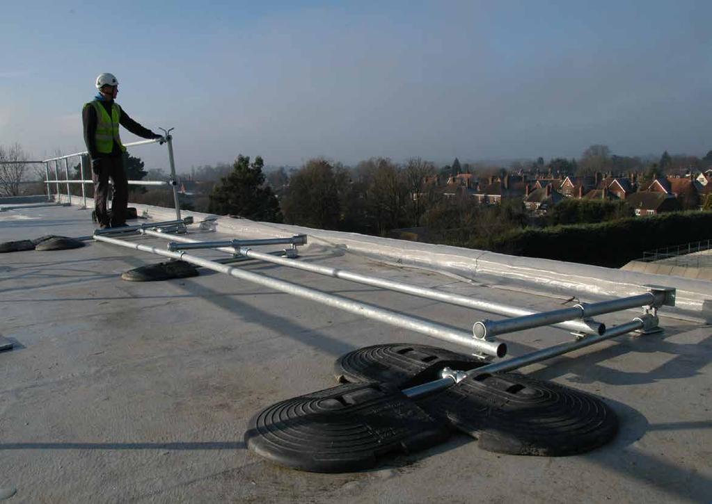
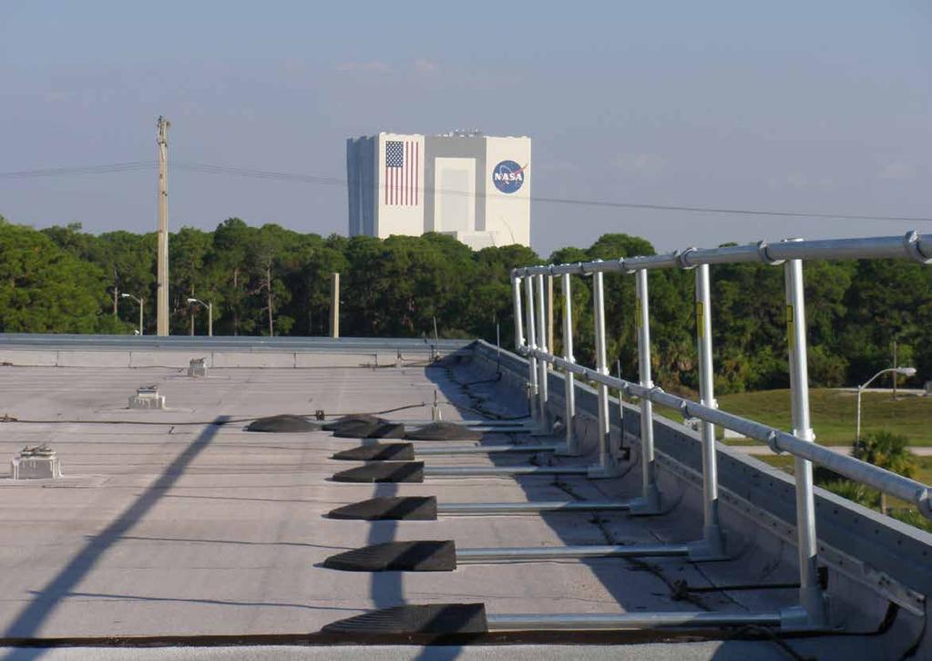
3 KeeGuard System Overview SAFETY GUARDRAIL SYSTEMS The Company s guardrail system KEEGUARD has been designed specifically to provide permanent edge protection for areas where regular access for maintenance and inspection is required. UNIQUE SYSTEMS Each system s unique design provides permanent edge protection without the need to mechanically fix the system through the roofing membrane or building s structure. Their simple cantilever principle provides unrivalled strength, stability and safety and overcomes the problems associated with traditional systems such as having to drill and puncture the roof membrane which can lead to potential penetrative water damage and noise disturbance during installation. Similarly, high levels of insulation included within warm deck and inverted flat roof designs often mean it is virtually impossible to fix through, as with traditional systems, without causing cold bridging. This may then cause interstitial condensation to form within the flat roof construction, causing the roof to deteriorate and eventually require replacement. When it is not appropriate to use counter balanced systems, such as modern industrial cladded pitched roofs, KeeGuard Topfix may be an alternative to traditionally fixed systems. DURABLE SYSTEMS The Company s guardrail components are supplied with a galvanised finish carried out to BS EN ISO 1461 and ASTM A53: Hot Dip Galvanised Coatings Specification and Testing Methods, giving an average coating of between microns. All products are also available in aluminium. All cast clamps have Threadkoat applied to all tapped holes. All grub screws are carbon steel and have Keekoat protection applied to ensure minimal maintenance. COMPONENT BASED SYSTEMS All systems consist of galvanised/aluminium tubing joined together using the KEE KLAMP method of connection. KEEGUARD, raked, radiused and folding systems base feet connect to the 100% recycled PVC counter weight, giving the system its strength & stability. 3 VERSATILE SYSTEMS All systems have been specially designed to fit any shape and size of flat and pitched roofs, even circular designs. The systems can also cope with changes in levels, roof falls and difficult details such as ductwork passing over the roof edge and cable trays/plant mounted at the roof edge. The lexibility of the counter weight & KEE KLAMP design allows the systems to be used on plant congested or complex detailed roofs. The product range has been extended to suit specific requirements and includes the standard design with vertical legs, raked and radiused systems, as well as a folding version for areas where a more discreet form of protection is required. KeeGuard Topfix has also been added to the range to provide collective protection solutions for industrial cladded pitched roofs.


4 KeeGuard System Overview MEMBRANE PROTECTION SYSTEMS Each system is installed with rubber matting bonded to the underside of metal components which come into contact with the roof membrane. In some cases the counter weight and base foot have sacrificial pads placed between the edge protection components and the roof membrane. This protects the roof membrane from damage via heat transfer or direct contact with components. On warm deck roof construction specifications pedestrian tiles are recommended to be placed where base feet and counter weights are in contact with the roof membrane. Where KeeGuard Topfix is installed a butyl strip is used where the Base Plates are fixed, via rivets, to the roof cladding. TESTING & CERTIFICATION Tested in accordance with:- EN Class A. EN ISO Part 3. NF E EN BS 6399 : Part 2 Code of Practice for Wind Load. WIND CALCULATED Wind loading is the most likely regular and demanding force a free standing roof guardrail will encounter during its lifetime. The Company has developed a computerised programme to calculate the design to ensure compliance with the relevant wind loadings relating to the topography, height and location of the project throughout the World. OFFICIAL DOCUMENTATION All Systems comply with the following:- Work at Height Regulations. HSG 33 Health & Safety in Roof work HSE Construction Sheet No. 21 Working on flat roofs protection against falls. European Union Directives together with requirements of CDM Regulations. AESTHETICS The smooth lines of the standard galvanised/aluminium finish can be further enhanced by the application of powder coating to BS 6497 Specification for Powder Organic Coatings, EU Codes with bespoke colour produced to special order. Counter weights are available in black or other colours at an additional cost. Where a more discreet form of protection is required, raked and radiused systems, as well as a folding version are welcomed by Planning Officers due to their improved aesthetics. SYSTEMS DISTRIBUTORS All systems are available as a supply and installation service or component supply only. Products are available from The Company directly or one of its licensed distributors. INDUSTRIAL CLADDED ROOFS The Company has developed a new collective roof edge protection system, KeeGuard Topfix specifically for metal profile and standing seam roofs up to 45. Pitched cladded roofs have traditionally been protected using personal fall protection systems which are lower in the hierarchy of controls. 4

5 KeeGuard Foldshield Compliance to EN PRODUCT SPECIFICATION - EN FEATURES :- Standard Vertical Folding Guardrail System. Recycled PVC Counter Weight System. GENERAL KeeGuard systems do not require physical fixing into the roof s structure/membrane. The complete system s design, manufacture, testing and installation has been externally assessed and tested to EN MATERIALS Steel tubing to BS EN mm. Steel tubing to EN mm. All steel components galvanised to BS EN ISO Guardrail top and intermediate rails are produced in steel mm external diameter (Wall thickness 3.2mm). The vertical support legs are produced in steel mm external diameter (Wall thickness 3.2mm). Cantilever tubes are produced in steel mm external diameter (Wall thickness 3.2mm). All cast clamps have Threadkoat applied to all tapped holes. All grub screws are carbon steel and have Keekoat protection applied to ensure minimal maintenance. All cast clamps used to join the guardrail are galvanised malleable cast iron produced to BS EN 1562 : founding malleable cast iron. All metal components in contact with the roof membrane are covered with 3mm fluted rubber. Counter weights are manufactured from recycled PVC. Where tubing is cut on site zinc rich paint is applied to the cut end of the tube. LAYOUT Height of guardrail is set at 1100mm. All vertical supports are set at maximum 3m centres depending on the system. Standard system is formed of 6m bays connected by two cantilevered T sections with connecting tube. Recycled PVC counter weights are attached to every vertical leg set at no more than 3m centres. At corner Support Legs there is no need for a PVC Counter Weight to be connected. All stop ends are triple counter weighted or supported by way of a wall/ladder clamp. TESTING All systems have been tested to EN 13374: Temporary Edge Protection Systems - Product Specification Test Methods and have been awarded a Class A Pass. EN Roof Type MAX Tube Tube End Counter MAX Bay Intermediate Pitch Size Thickness Balance Centres Counter No. s Balance No. s Mineral Grade Felt Restrained mm CB2 3m 1 UnRestrained mm CB3 3m 1 PVC Membrane Restrained mm CB2 3m 1 UnRestrained mm CB7 3m 1 UnRestrained mm CB5 3m 1 WIND LOADING All installations are wind speed calculated to BS 6399 : Part 2 : Code of Practice for Wind Loads. 5

6 KeeGuard Foldshield Compliance to EN PRODUCT SPECIFICATION EN & NF E FEATURES:- Standard Vertical Folding Guardrail System. Recycled PVC Counter Weight System. GENERAL KeeGuard systems do not require physical fixing into the roof s structure/membrane. The complete system s design, manufacture, testing and installation has been externally assessed and tested to EN & NF E MATERIALS Steel tubing to BS EN mm Steel tubing to EN mm All steel components galvanised to BS EN ISO Guardrail top and intermediate rails are produced in steel mm external diameter (Wall thickness 3.2mm). The vertical support legs are produced in steel mm external diameter (Wall thickness 4.0mm). Cantilever tubes are produced in steel mm external diameter. (Wall thickness 3.2mm). All cast clamps have Threadkoat applied to all tapped holes. All grub screws are carbon steel and have Keekoat protection applied to ensure minimal maintenance.. All cast clamps used to join the guardrail are galvanised malleable cast iron produced to BS EN 1562 : founding malleable cast iron. All metal components in contact with the roof membrane are covered with 3mm rubber. Counter weights are manufactured from recycled PVC. Where tubing is cut on site zinc rich paint is applied to the cut end of the tube. LAYOUT Height of guardrail is set at 1100mm. All vertical supports are set at maximum 2.4m centres depending on the system. First bay of all installations vertical supports are set at maximum 2.0m centres. Recycled PVC counter weights are attached to every vertical leg set at no more than 2.4m centres. At corner Support Legs there is no need for a PVC Counter Weight to be connected. All stop ends are appropriately counter weighted according to roof pitch and membrane (see table) or supported by way of a wall/ladder clamp. TESTING All systems have been tested to EN & NF E WIND LOADING All installations are wind speed calculated to Eurocode 1: Actions on structures - Part 1-4: General actions - Wind loads 6 EN & NF E Roof Type MAX Tube Tube End MAX Intermediate MAX Pitch Size Thickness Counter End Bay Counter Subsequent Length Balance No. s Bay Lengths Mineral Grade Felt UnRestrained mm CB4 2m 1 2.4m HEAD OFFICE Kee Safety Limited Cradley Business Park Overend Road Cradley Heath West Midlands B64 7DW (t) +44 (0) (f) +44 (0) (e) info@keesafety.co.uk (w) CANTILEVERED ROOF EDGE PROTECTION SEPARATING PEOPLE FROM HAZARDS THIS GUARDRAIL IS TESTED TO OSHA & OBC DO NOT REMOVE, TAMPER, ADJUST, REMOVE OR ALTER IN ANY WAY THE GUARDRAIL INSTALLATION WITHOUT FIRST CONSULTING KEE SAFETY. NO LANYARD LIFE LINE OR FALL ARREST PRODUCTS TO BE ATTACHED TO THE GUARDRAIL AT ANY TIME DO NOT ATTACH PLASTIC SHEETING OR ANYTHING THAT WOULD INCREASE THE WIND LOADING ON THE GUARDRAIL. IF YOU FIND THE GUARDRAIL HAS BEEN ALTERED OR TAMPERED WITH, CONTACT KEE SAFETY IMMEDIATELY RE-TEST ONLY TO BE CARRIED OUT BY AUTHORISED SERVICE AGENT. SYSTEM PLAQUE - SL 111 Provides details of the system and approvals. Material : Plastic. Net weight : 0.085kg.


7 Typical Edge Protection System Layout FIGURE 1 Free Standing End Detail Intermediate Counter Weight Intermediate Counter Weight NOTE: End Detail Refer to Product Specification Standard! 8


8 KeeGuard Foldshield Components EN & EN mm Size 8 53mm 110mm Size 7 55mm 175mm 85mm *HINGED VERSION BASE FOOT A This unique component provides support to the system and allows it to be set vertically at 90º. When the guardrail is not required this Base Foot allows the system to be folded flat on to the roof. The Base Foot connects the Cantilever Tubes and Counter Weights and is bonded with fluted rubber matting for membrane protection. Material : Malleable cast iron to BS 1562 and galvanised to BS EN ISO Net weight : 3.3kg. 60mm *SADDLE CLAMP This open cup fitting provides the method of linking the horizontal Main Rail Tubes to the Support Legs. Material : Malleable cast iron to BS 1562 and galvanised to BS EN ISO Net weight : 0.77kg. 68mm 68mm 90mm 90º-180º 90º ELBOW This provides the means of dealing with corners and changes in level. Material : Malleable cast iron to BS 1562 and galvanised to BS EN ISO Net weight : 0.76kg. ADJUSTABLE SIDE OUTLET TEE ELBOW Used in pairs these components deal with angles 90º-180ºand changes in level. Material : Malleable cast iron to BS 1562 and galvanised to BS EN ISO Net weight : 1kg. 136mm 104mm 68mm THREE SOCKET TEE CONNECTOR This component can be used in many different instances, for example, changes in level. Material : Malleable cast iron to BS 1562 and galvanised to BS EN ISO Net weight : 1.08kg. 9 STRAIGHT COUPLING This component provides the method to link the horizontal Main Rail Tubes. Material : Malleable cast iron to BS 1562 and galvanised to BS EN ISO Net weight : 0.6kg. * Sold as replacement parts only
 (1575mm - CBT2) This component provides the link between the Counter Weight and Base Foot. Material : Steel tubing to EN 10255-3.2mm.")
 KFU1 EN 13374 (2.")

9 KeeGuard Foldshield Components EN & EN O/D 42.4mm 1075mm 1575mm CANTILEVER TUBE - (1075mm - CBT1) (1575mm - CBT2) This component provides the link between the Counter Weight and Base Foot. Material : Steel tubing to EN mm. All steel components galvanised to BS EN ISO Cantilever tubes are produced in steel 42.4mm external diameter. (Wall thickness 3.2mm) First/ last Cantilever tube length 1575mm Net weight : 4.48kg. Intermediate cantilever tube length 1075mm Net weight : 3.26kg. 1100mm 11º STANDARD FOLDING SUPPORT LEG EN (3.2mm wall thickness) KFU1 EN (2.9mm wall thickness) KFU3X This component allows for standard 90º installation and provides some height adjustment to the system. This component also permits the system to fold. The vertical support legs are produced in steel mm external diameter. Material : Galvanised steel to BS EN ISO Net weight : 8.3kg. O/D 42.4mm 50mm 260mm SMALL CANTILEVER TUBE/COUNTER WEIGHT LINK - CBT3 Used in pairs at the end details these components provide the link between the Counter Weights and the Cantilever Tube via the Two Socket Cross fitting. Material : Steel tubing to EN mm. All steel components galvanised to BS EN ISO Tubes are produced in steel 42.4mm external diameter. (Wall thickness 3.2mm) Net weight : 0.78kg. PLASTIC CAP - SL105 This component is fitted to the top of the Support Leg to prevent water ingress. Material : PVC. Net weight : 0.009kg. O/D 48.3mm 100mm 125mm 6.4m, 3.2m or 2.133m MAIN RAIL TUBE EN (3.2mm wall thickness) (6.4m )(3.2m HL)(2.133m ) EN (2.9mm wall thickness) (6.4m )(3.2m HL)(2.133m ) Supplied in three sizes for convenience, these components provide the horizontal rails of the system. Guardrail top and intermediate rails are produced in steel mm external diameter. Material : Steel tubing to BS EN mm. Steel tubing to EN mm. All steel components galvanised to BS EN ISO Net weight : 22.9kg, 11.45kg. & 7.6kg 10 75mm WALL/LADDER CLAMP - SL109C This component provides the means to terminate the system against a façade or clamp the system to a cat ladder/structure where the stringer is a maximum of 70mm wide. Material : Galvanised steel to BS EN ISO Net weight : 1.1kg.


10 KeeGuard Foldshield Components EN & EN mm 460mm *RECYCLED PVC COUNTER WEIGHT This component provides the stability to the system. Material : Recycled PVC Net weight : 13.3kg. 500mm 120mm TWO SOCKET CROSS This component is used where two recycled PVC Counter Weights need to be joined together to form a counter weight end detail. Material : Malleable cast iron to BS 1562 and galvanised to BS EN ISO Net weight : 0.63kg. 136mm 65mm COLLAR This component is inserted in the first slot of the recycled PVC Counter Weight. The cantilever tube is pushed through this fitting and the grub screw is then tightened. This component provides the connection between the Cantilever Tube and the Counter Weight. Material : Malleable cast iron to BS 1562 and galvanised to BS EN ISO Net weight : 0.24kg. 68mm THREE SOCKET TEE CONNECTOR This component can be used in many different instances, for example, changes in level. Material : Malleable cast iron to BS 1562 and galvanised to BS EN ISO Net weight : 1.08kg. 1m 1m 466mm 500mm 466mm 500mm European Gate - Galvanised - SGEU500GV Spring Loaded, self-closing safety gate. Manufactured from steel to EN mm diameter tube x 3.2mm wall thickness to meet requirements of EN & EN Complete with fixing pack. Material : Galvanised steel to BS EN ISO Net weight : 11kg (24lb 4oz). European Gate Powder Coated - SGEU500PC Spring Loaded, self-closing safety gate. Manufactured from steel to EN mm diameter tube x 3.2mm wall thickness to meet requirements of EN & EN Complete with fixing pack. Powder Coated Finish to EN Material : Steel to EN Net weight : 11kg (24lb 4oz). 11
11

 Main Rail Tubes (8610) or (3.2m (10 6 ) or 2.13m (7 0)) side by side and in a continual line for the bay.")
 (EN 14122-3 2.4m centres) (OSHA Regs 8 centres). Note:- (3No.")
12 KeeGuard Foldshield Assembly Guide STANDARD SUPPORT LEG (KFU1) These are supplied already assembled at the correct height (1100mm) (42 ) with the Base Foot & saddle Clamps set at the correct position. LAYING OUT SUPPORT LEG AND MAIN RAIL TUBES Lay out the equipment in approximately the positions shown below. Always ensure that you and the equipment are at a safe distance from the roof edge. It is recommended that this distance is no less than 2m (6 6 ). Lay out two 6.4m (21 ) Main Rail Tubes (8610) or (3.2m (10 6 ) or 2.13m (7 0)) side by side and in a continual line for the bay. Continue for the complete guardrail length required (ensure these do not roll towards the roof edge). Then start laying out the Support leg Units. If your start position is from a corner, start laying out the support legs at a maximum of the following centres (EN m centres) (EN m centres) (OSHA Regs 8 centres). Note:- (3No. Support Legs per bay). Where bays meet (Every 6m 6 6 )) place 2No. Support Legs next to one another (see below). Carry on laying out the Support Legs for the required length of guardrail (KFU1). Please refer to technical specification KFU1 18
 2No. End pieces 6No. PVC Counter Weights (440-7) (EN 13374) 2No. Cantilever Tube (CBT2) 4No. Small Cantilever Tube Link (CBT3) 2No. Two Socket Cross (26-7) 6No. Collars (74-7) 6No.")
 (OSHA Regs) 2No. Cantilever Tube (CBT2) 14No. Small Cantilever Tube Link (CBT3) 6No. Two Socket Cross (26-7) 14No. Collars (74-7) 16No.")
 B FREE STANDING END Extra components 2No. 90 Elbows (15-8) 1No. End piece 3No. PVC Counter Weights (440-7) EN 13374) 1No. Cantilever Tube (CBT2) 2No.")
13 KeeGuard Foldshield Assembly Guide Fixed, Free Standing and Intermediate Details (See tables and specifications) A SELF CLOSING GATE ACCESS POINT Extra components 1No. Self Closing Gate (GT25P) 4No. 90 Elbows (15-8) 2No. End pieces 6No. PVC Counter Weights (440-7) (EN 13374) 2No. Cantilever Tube (CBT2) 4No. Small Cantilever Tube Link (CBT3) 2No. Two Socket Cross (26-7) 6No. Collars (74-7) 6No. PVC Counter Weights (440-7) (EN ) 2No. Cantilever Tube (CBT2) 8No. Small Cantilever Tube Link (CBT3) 4No. Two Socket Cross (26-7) 8No. Collars (74-7) 14No. PVC Counter Weights (440-7) (OSHA Regs) 2No. Cantilever Tube (CBT2) 14No. Small Cantilever Tube Link (CBT3) 6No. Two Socket Cross (26-7) 14No. Collars (74-7) 16No. PVC Counter Weights (440-7) CAL OSHA Regs) 2No. Cantilever Tube (CBT2) 16No. Small cantilever Tube Link (CBT3) 8No. Two Socket Cross (26-7) 16No. Collars (74-7) B FREE STANDING END Extra components 2No. 90 Elbows (15-8) 1No. End piece 3No. PVC Counter Weights (440-7) EN 13374) 1No. Cantilever Tube (CBT2) 2No. Small cantilever Tube Link (CBT3) 1No. Two Socket Cross (26-7) 3No. Collars (74-7) 4No. PVC Counter Weights (440-7) EN 14122) 1No. Cantilever Tube (CBT2) 4No. Small cantilever Tube Link (CBT3) 2No. Two Socket Cross (26-7) 4No. Collars (74-7) 7No. PVC Counter Weights (440-7) OSHA Regs) 1No. Cantilever Tube (CBT2) 6No. Small cantilever Tube Link (CBT3) 3No. Two Socket Cross (26-7) 7No. Collars (74-7) 8No. PVC Counter Weights (440-7) CAL OSHA Regs) 1No. Cantilever Tube (CBT2) 8No. Small cantilever Tube Link (CBT3) 4No. Two Socket Cross (26-7) 8No. Collars (74-7) C WALL CLAMP Extra components 1No. End piece 1No. Three Socket Tee Connector (25-8) 1No. Wall/Ladder Clamp (SL109C) 2No. 90º Elbows (15-8) 2No. Wall Fixings (SL110) 19
14 KeeGuard Assembly Guide FIXED, FREE STANDING AND INTERMEDIATE DETAILS LAYING OUT LAYING OUT COUNTER WEIGHTS AND CANTILEVER TUBES Where the 2No. Main Rail Tubes butt together lay out 2No. Straight Couplings (14-8) in order for the Main Rail Tubes to be joined. At corners 2No. 90º Elbows will be used (15-8). (Use Adjustable Side Outlet Tee Elbows in pairs where corners are 90º º (19-8)). See also Fixed, Free Standing and Intermediate Details above for additional required components. (See Figure1.) EN13374 At any free standing end detail Support Leg, place 1No. Cantilever Tube (CBT2), 1No. Two Socket Cross Clamp (26-7), 2No. Small Cantilever Tubes (CBT3), 3No. PVC Counter Weights (440-7) and 3No. Collars (74-7) At the intermediate Support Legs (max 3m centres) place 1No. Cantilever Tube (CBT1), 1No. PVC Counter Weight (440-7), and 1No. Collar (74-7). At corner Support Legs there is no need for a PVC Counter Weight to be connected (See Figure1 and specification.). EN At any free standing end detail Support Leg, place 1No. Cantilever Tube (CBT2), 2No. Two Socket Cross Clamp (26-7), 4No. Small Cantilever Tubes (CBT3), 4No. PVC Counter Weights (440-7) and 4No. Collars (74-7) EN Roof Type MAX Tube Tube End Counter MAX Bay Intermediate Pitch Size Thickness Balance Centres Counter No. s Balance No. s Mineral Grade Felt Restrained mm CB2 3m 1 UnRestrained mm CB3 3m 1 PVC Membrane Restrained mm CB2 3m 1 UnRestrained mm CB7 3m 1 UnRestrained mm CB5 3m 1 EN & NF E Roof Type MAX Tube Tube End MAX Intermediate MAX Pitch Size Thickness Counter End Bay Counter Subsequent Length Balance No. s Bay Lengths Mineral Grade Felt UnRestrained mm CB4 2m 1 2.4m At the intermediate Support Legs(First bay max 2m centres) (Subsequent bays max 2.4m centres) place 1No. Cantilever Tube (CBT1), 1No. PVC Counter Weight (440-7), and 1No. Collar (74-7). (See Figure1 and specification). LAYING OUT FITTINGS Where the 2No. Main Rail Tubes butt together lay out 2No. Straight Couplings (14-8) in order for the Main Rail Tubes to be joined. At corners 2No. 90º Elbows will be used (15-8). (Use Adjustable Side Outlet Tee Elbows in pairs where corners are 90º º (19-8)). See also Fixed, Free Standing and Intermediate Details above for additional required components. (See Figure1.) 20
15 KeeGuard Assembly Guide FIXED, FREE STANDING AND INTERMEDIATE DETAILS LAYING OUT LAYING OUT COUNTER WEIGHTS AND CANTILEVER TUBES At any free standing end detail Support Leg, place 1No. Cantilever Tube (CBT2), 3No. Two Socket Cross Clamp (26-7), 6No. Small Cantilever Tubes (CBT3), 7No. PVC Counter Weights (440-7) and 7No. Collars (74-7) Subsequent Bays At the remaining intermediate Support Legs (max 8 centres) place 1No. Cantilever Tube (CBT1), 1No. PVC Counter Weight (440-7), and 1No. Collar (74-7). (See Figure and specification). CAL OSHA Regs At any free standing end detail Support Leg, place 1No. Cantilever Tube (CBT2), 4No. Two Socket Cross Clamp (26-7), 8No. Small Cantilever Tubes (CBT3), 8No. PVC Counter Weights (440-7) and 8No. Collars (74-7) First Bay (3 3 max) Place 1No. Cantilever Tube (CBT2), 3No. Two Socket Cross Clamp (26-7), 6No. Small Cantilever Tubes (CBT3), 6No. PVC Counter Weights (440-7) and 6No. Collars (74-7) Subsequent Bays At the remaining intermediate Support Legs (max 6 6 centres) place 1No. Cantilever Tube (CBT1), 1No. PVC Counter Weight (440-7), and 1No. Collar (74-7). (See Figure and specification). LAYING OUT FITTINGS Where the 2No. Main Rail Tubes butt together lay out 2No. Straight Couplings (14-8) in order for the Main Rail Tubes to be joined. At corners 2No. 90º Elbows will be used (15-8). (Use Adjustable Side Outlet Tee Elbows in pairs where corners are 90º º (19-8)). See also Fixed, Free Standing and Intermediate Details above for additional required components. (See Figure1.) Roof Type Max Pitch Mineral Grade Felt Tube Size Tube Thickness (inches) USA & CANADA End Counter Balance No s End Bay Length (feet) 2nd Vertical Leg Counter Balance No s Subsequent Counter Balance No s Susequent Bay Length (feet) Unrestrained 5º CB7 8 CB1 CB1 8 Unrestrained 5º CB4 3 3 CB3 CB1 8 Unrestrained 10º CB8 6 6 CB1 CB1 6 6 TPO - Single Ply Membrane Unrestrained 5º CB7 8 CB1 CB1 8 Unrestrained 10º CB8 6 6 CB1 CB1 6 6 EPDM - Single Ply Membrane Unrestrained 5º CB7 8 CB1 CB1 8 Unrestrained 10º CB8 6 6 CB1 CB1 6 6 Roof Type Max Pitch Mineral Grade Felt Tube Size Tube Thickness (inches) CAL OSHA End Counter Balance No s End Bay Length (feet) 2nd Vertical Leg Counter Balance No s Subsequent Counter Balance No s Susequent Bay Length (feet) Unrestrained 5º CB8 3 3 CB6 CB
 and 2No end pieces. At corners place 2No. 90º Elbows (15-8), 2No. Straight Couplings (14-8) and 2No. 8 lengths of Main Rail Tubes.")
16 KeeGuard Foldshield Assembly Guide LAYING OUT FITTINGS Where the 2No. Main Rail Tubes butt together lay out 2No. Straight Couplings (14-8) in order for the Main Rail Tubes to be joined. Where the 6 6 bays butt to one another place 4No. 90º Elbows (15-8) and 2No end pieces. At corners place 2No. 90º Elbows (15-8), 2No. Straight Couplings (14-8) and 2No. 8 lengths of Main Rail Tubes. (Use Adjustable Side Outlet Tee Elbows in pairs where corners are 90º º (19-8)). See also Fixed, Free Standing and Intermediate Details above for additional required components. (See Figure1.) STAGE 1 Starting at least 2m (6 6 ) away from the roof edge at the corner, stand up the two Support Legs. STAGE 3 Form a corner via connecting 2No 90º Elbows (15-8) to one end of each of the Main Rail Tubes (8610). Position a further Support Leg 250mm (10 ) max from the corner. Connect 1No. 200mm (8 ) length of Main Rail Tube to each of the 90º Elbows (15-8). Slide 1No. Straight Coupling (14-8) on to each of the 200mm (8 ) lengths of Main Rail Tubes. Slide a Main Rail Tube (8610) into the bottom Saddle Clamp (135-8) and Straight Coupling (14-8).Slide a Main Rail Tube (8610) into the top Saddle Clamp (135-8) and Straight Coupling (14-8). Tighten the grub screws of all clamps. STAGE 2 Place a Main Rail Tube (8610) into the bottom Saddle Clamp (135-8) of each of the standing legs. Position the tube so there is at least 60mm (2-1/2 ) protruding from the Saddle Clamp (135-8) and tighten the Grub Screw. These are located on the front of the Saddle Clamp (135-8). Place the second Main Rail Tube (8610) into the top Saddle Clamp (135-8), positioning the tube as before, leaving at least 60mm (2-1/2 ) of the tube protruding from the Saddle Clamp (135-8) and tighten the Grub Screw of the Saddle Clamp (135-8). STAGE 4 Working in pairs carefully lift the assembled bay and walk towards the leading edge. Carefully place the bay in the desired position and slide the corresponding Counter Weight tube into the Base Foot/Feet. (CBT1) Intermediate & Abutment Support Legs or CBT2 (Free Standing End Detail) Always ensure the bay is being held in position whist carrying out this part of the assembly. At the corner support Leg connect 2No. Cantilever Tubes together using Three Socket Tee Connector (25-7) as shown below. Tighten all grub screws. 22
17 KeeGuard Foldshield Assembly Guide STAGE 5 Place 1No. Collar (74-7) in the front slot of the PVC Counter Weight. Slide 1No. PVC Counter Weight on to the free end of the Cantilever Tube (CBT1). Line and level guardrail. Tighten all grub screws. STAGE 7 Continue to assemble the components to form each 6m (6 6 ) bay. Where bays abut one another connect the top and intermediate Main Rail Tubes together by sliding 1No. 90º Elbow (15-8) on to each of the 4No. Main Rail Tubes. Insert an end piece between each pair of 90º Elbow (15-8). Line, level and tighten all grub screws. STAGE 6 Slide 1 No Three Socket Tee Connector (25-7) on to each of the Cantilever Tubes (CBT1) Place 1No. Collar (74-7) in the front slot of each PVC Counter Weight. Slide the PVC Counter Weights on to each of the free end of the Cantilever Tubes (CBT1). Line and level guardrail. Tighten all grub screws. STAGE 8 Free Standing End Details (Refer to tables within specification page) EN Slide 1No. Two Socket Cross (26-7) on to the free end of the Cantilever Tube (CBT2). Do not tighten at this stage. Slide 2No. Small Cantilever Tubes into the free ends of the Two Socket Cross (26-7) and tighten the grub screws holding these tubes into position. Place 1No. Collar (74-7) in the front slot of each PVC Counter Weight. Slide 1No. PVC Counter Weight on to the free end of the Cantilever Tube (CBT2). Slide 1No. PVC Counter Weight on to each of the free ends of the Small Cantilever Tube (CBT3). EN Slide 2No. Two Socket Cross (26-7) on to the free end of the Cantilever Tube (CBT2). Do not tighten at this stage. Slide 4No. Small Cantilever Tubes into the free ends of each of the Two Socket Cross (26-7) and tighten the grub screws holding these tubes into position. Place 1No. Collar (74-7) in the front slot of each PVC Counter Weight. Slide 1No. PVC Counter Weight on to each of the free ends of the Small Cantilever Tube (CBT3). 23
18 KeeGuard Foldshield Assembly Guide OSHA Regs Slide 3No. Two Socket Cross (26-7) on to the free end of the Cantilever Tube (CBT2). Do not tighten at this stage. Slide 6No. Small Cantilever Tubes into each of the free ends of the Three Socket Cross (26-7) and tighten the grub screws holding these tubes into position. Place 1No. Collar (74-7) in the front slot of each PVC Counter Weight. Slide 1No. PVC Counter Weight on to the free end of the Cantilever Tube (CBT2). Slide 1No. PVC Counter Weight on to each of the free ends of the Small Cantilever Tube (CBT3) Position all PVC Counter Weights as far from the Base Foot ( ) as practically possible. Line and level guardrail. Tighten all grub screws. (See Fixed, Free Standing and intermediate Details). EN Roof Type MAX Tube Tube End Counter MAX Bay Intermediate Pitch Size Thickness Balance Centres Counter No. s Balance No. s Mineral Grade Felt Restrained mm CB2 3m 1 UnRestrained mm CB3 3m 1 PVC Membrane Restrained mm CB2 3m 1 UnRestrained mm CB7 3m 1 UnRestrained mm CB5 3m 1 EN & NF E Roof Type MAX Tube Tube End MAX Intermediate MAX Pitch Size Thickness Counter End Bay Counter Subsequent Length Balance No. s Bay Lengths Mineral Grade Felt UnRestrained mm CB4 2m 1 2.4m WARNING Under no circumstances should any person be anchored to the system for fall arrest purposes. Further, components such as timber infill, advertising boards, polyethylene sheets must not be fixed to the system. Roof Type Max Pitch Tube Size Tube Thickness (inches) CAL OSHA End Counter Balance No s End Bay Length (feet) 2nd Vertical Leg Counter Balance No s Subsequent Counter Balance No s Susequent Bay Length (feet) Mineral Grade Felt Unrestrained 5º CB8 3 3 CB6 CB1 6 6 Roof Type Max Pitch Tube Size Tube Thickness (inches) USA & CANADA End Counter Balance No s End Bay Length (feet) 2nd Vertical Leg Counter Balance No s Subsequent Counter Balance No s Susequent Bay Length (feet) Mineral Grade Felt Unrestrained 5º CB7 8 CB1 CB1 8 Unrestrained 5º CB4 3 3 CB3 CB1 8 Unrestrained 10º CB8 6 6 CB1 CB1 6 6 TPO - Single Ply Membrane Unrestrained 5º CB7 8 CB1 CB1 8 Unrestrained 10º CB8 6 6 CB1 CB1 6 6 EPDM - Single Ply Membrane Unrestrained 5º CB7 8 CB1 CB1 8 Unrestrained 10º CB8 6 6 CB1 CB


19 KeeGuard Foldshield - Typical Layout and Use STAGE 9 When desired the system can simply be lowered in 6m bay lengths. Carefully remove the pins from the 2No. end base feet. Then remove the pin of the centre Base Foot and move backwards & lower the guardrail. Note:- Ensure you are using appropriate PPE and anchored to an approved anchorage point before commencing. 25 NOTE: End Detail Refer to Product Specification Standard and following pages.
20
21 KeeGuard Foldshield Layout EN All Bays Max 3m 27 EN Roof Type MAX Tube Tube End Counter MAX Bay Intermediate Pitch Size Thickness Balance Centres Counter No. s Balance No. s Mineral Grade Felt Restrained mm CB2 3m 1 UnRestrained mm CB3 3m 1 PVC Membrane Restrained mm CB2 3m 1 UnRestrained mm CB7 3m 1 UnRestrained mm CB5 3m 1

22 KeeGuard Foldshield Layout EN & NF E First Bay 2m Subsequent Bays 2.4m EN & NF E Roof Type MAX Tube Tube End MAX Intermediate MAX Pitch Size Thickness Counter End Bay Counter Subsequent Length Balance No. s Bay Lengths Mineral Grade Felt UnRestrained mm CB4 2m 1 2.4m 28
23 KeeGuard Foldshield Recertification Periodic inspections by a competent person are recommended by the manufacturer. In UK/Europe these are required under Regulation 5 of the Workplace (Health, Safety & Welfare) Regulations, the Work at Height Regulations and BS EN 365. The frequency will depend upon the environment, location and usage but should be at least every 12 months. Walk and visually inspect the complete installed system in relation to the general client s needs. Establish if any modifications and/or additional products are required to reflect any refurbishment requirements or additional plant & equipment which have been installed and require access. Check installation configuration is complete as per the original installation drawing/plan. Ensure the system has not been modified or tampered with by unauthorised persons. Check all base feet are in contact with the roof membrane. Check all counter weights are in place as per the original drawing. This is essential for wind loading calculations. Check all grub screws are in place, greased and sufficiently torque. Check that the general height and level of the system including the leg centres. (This only tends to be an issue if the system has been tampered with between inspections). Any galvanised components showing signs of corrosion should be wire brushed thoroughly and galvanised spray/paint applied as appropriate. If rusted significantly, take digital photographs and include these in the inspection report. Where toe-boards are fitted check the brackets that support the toe-board are in place, greased and sufficiently torqued. Where applicable, check fixings to walls/structures including cat ladder clamps are in place, greased and sufficiently torqued. Check system plaque position & mark up to reflect date of the next required inspection. Establish if additional plaques are required due to any refurbishment works. 31

 1384 632")

24 Kee Safety Limited Cradley Business Park Overend Road, Cradley Heath West Midlands B64 7DW, UK Phone: +44 (0) Fax: +44 (0)
KeeGuard Foldshield Operation & Maintenance Manual
 S A F E T Y A T T H E H I G H E S T L E V E L KeeGuard Foldshield Operation & Maintenance Manual 2 KeeGuard System Overview KEE SAFETY GUARDRAIL SYSTEMS KEEGUARD has been designed specifically to provide
KeeGuard Operation & Maintenance Manual
 S A F E T Y A T T H E H I G H E S T L E V E L KeeGuard Operation & Maintenance Manual 2 KeeGuard System Overview KEE SAFETY GUARDRAIL SYSTEMS KEEGUARD has been designed specifically to provide permanent
Roof Edge Fabrications Guardrails
 O&M - KEEGUARD Roof Edge Fabrications Guardrails ROOF EDGE FABRICATIONS GUARDRAILS Roof Edge Fabrications guardrail systems including System 2000 and KeeGuard have been designed specifically to provide
Think Safety, Think Safesite O&M - KEEGUARD
 Think Safety, Think Safesite O&M - KEEGUARD Safesite Guardrail Systems SAFESITE GUARDRAIL SYSTEMS Safesite s guardrail systems including System 2000 and KeeGuard have been designed specifically to provide
PORTABILITY The Kee Dome range has been designed in component form to ensure that it can be easily transported both to site and up to roof level.
 O&M - KEE DOME Kee Dome INTRODUCTION The Kee Dome range of modular systems has been designed specifically to prevent falls through rooflights. UNIQUE DESIGN These innovative products provide protection
The Safety Solution for Free Standing Roof Edge Protection
 S A F E T Y A T T H E H I G H E S T L E V E L Systems The Safety Solution for Free Standing Roof Edge Protection PROVIDES COLLECTIVE PROTECTION FOR ALL ROOF TOP WORKING MEETS THE REQUIREMENTS OF THE WORKING
Issue no: 10 Date: March Operation and Maintenance Manual Access Technologies Limited All rights reserved. 1 of 20
 Issue no: 10 Date: March 2012 Operation and Maintenance Manual Access Technologies Limited 2012. All rights reserved. 1 of 20 DEFENDER ROOF EDGE PROTECTION ECONOMY SYSTEM DEFENDER ROOF EDGE PROTECTION
Fall Protection Solutions
 PROVIDING SAFETY SOLUTIONS WORLD WIDE Fall Protection Solutions Kee Guard The safety solution for free standing roof top fall protection Kee Dome The safety solution for skylight fall protection Kee Anchor
SECTION HANDRAILS AND RAILINGS. A. Section Metal Fabrications: Associated metal supports.
 SECTION 05520 HANDRAILS AND RAILINGS PART 1 GENERAL 1.1 SECTION INCLUDES A. Handrails and guardrails B. Guardrails for hatches and openings. C. Safety barriers. D. Roof edge protection. 1.2 RELATED SECTIONS
Safety Barrier Solutions
 S E P A R A T I N G P E O P L E F R O M H A Z A R D S Safety Barrier Solutions SOLUTIONS TO YOUR BARRIER NEEDS SIMPLE TO DESIGN AND SPECIFY UNRIVALLED TECHNICAL SUPPORT WORLDWIDE AVAILABILITY The Kee Safety
SECTION ROOF EDGE SAFETY RAILING SYSTEM
 SECTION 07720 ROOF EDGE SAFETY RAILING SYSTEM PART 1 GENERAL 1.1 SECTION INCLUDES A. Provide and install freestanding KeeGuard Roof Edge Protection System, including pipe railings, uprights, bases, counterweights,
Safety Barrier Solutions
 S E P A R A T I N G P E O P L E F R O M H A Z A R D S Safety Barrier Solutions NO DRILLING OR WELDING NO HOT WORK PERMIT REQUIRED COST EFFECTIVE MEET SAFETY STANDARDS The Kee Safety Concept KEE SAFETY
EZI FOR A HANDRAIL & BARRIER SOLUTIONS REASON BARRIERS TUBE & FITTINGS HANDRAILS GUARDRAILS
 EZI FOR A REASON HANDRAIL & BARRIER SOLUTIONS HANDRAILS GUARDRAILS BARRIERS TUBE & FITTINGS WWW.EZIKLAMPSYSTEMS.COM CONTENTS 03 WELCOME TO EZI KLAMP SYSTEMS 05 EZI KLAMP TUBE & FITTINGS 08 FREE-STANDING
FSR - Roof Guardrail with Rubber Counterweights. Fold down option available. Lockinex. ea i, ea u i R2_11/17
 FSR - Roof Guardrail with Rubber Counterweights Fold down option available Lockinex ea i, ea u i R2_11/17 INTRODUCTION Lockinex FSR-Freestand Roof Guardrail system utilises Lockinex Key Clamps,Tubing &
Kee Line. The Safety Solution for Engineered Life Lines
 Kee Line S A F E T Y A T T H E H I G H E S T L E V E L The Safety Solution for Engineered Life Lines Conforms to EN 795 Class C and patent protected by GB 2389386 Cost effective engineered horizontal life
Fall Protection Solutions
 S E P A R A T I N G P E O P L E F R O M H A Z A R D S Fall Protection Solutions COMPREHENSIVE RANGE OF COLLECTIVE AND PERSONAL FALL PROTECTION SYSTEMS COMPLIANT WITH RELEVANT INTERNATIONAL STANDARDS GLOBAL
Fall Protection Solutions
 S E P A R A T I N G P E O P L E F R O M H A Z A R D S Fall Protection Solutions COMPREHENSIVE RANGE OF COLLECTIVE AND PERSONAL FALL PROTECTION SYSTEMS COMPLIANT WITH RELEVANT INTERNATIONAL STANDARDS GLOBAL
Fall Protection Solutions
 S E P A R A T I N G P E O P L E F R O M H A Z A R D S Fall Protection Solutions COMPREHENSIVE RANGE OF COLLECTIVE AND PERSONAL FALL PROTECTION SYSTEMS COMPLIANT WITH RELEVANT INTERNATIONAL STANDARDS GLOBAL
Kee Walk Step Over Instructions for Use Manual
 S A F E T Y A T T H E H I G H E S T L E V E L Kee Walk Step Over Instructions for Use Manual Contents SECTION CONTENTS PAGE 1 Introduction 1 1.1 Validity 1 1.2 Authorised Agent 1 1.3 Compatibility 1 1.4
FREESTAND ROOF GUARDRAIL. Lockinex. ea i, ea u i
 FREESTAND ROOF GUARDRAIL Lockinex ea i, ea u i INTRODUCTION Lockinex Freestand Roof Guardrail system utilises Lockinex Key Clamps,Tubing & concrete counterweights seated on rubber mats and does not require
ManSafe for Roofing. Product Selector E-H-SG-EU-001
 ManSafe for Roofing Product Selector EU E--SG-EU-001 The Complete Roof Access Solution The Latchways Product Selector is designed to help you identify the part numbers of the products required to provide
Safesite Suregrip Walkway System
 SUREGRIPWALKWAYSYSTEM SUREGRIP SYSTEM Safesite Suregrip Walkway System INTRODUCTION Working on roofs can be extremely dangerous, especially in wet or wintry conditions. Safesite's Suregrip provides a means
ManSafe for Roofing. Product Selector E-H-SG-UK-001
 ManSafe for Roofing Product Selector UK E--SG-UK-001 The Complete Roof Access Solution The Latchways Product Selector is designed to help you identify the part numbers of the products required to provide
SECTION PORTABLE RAILING SYSTEM
 SECTION 05520 PORTABLE RAILING SYSTEM Peak Fall Protection specializes in the design, engineering, fabrication, installation, and certification of fall protection safety systems. Our team of safety professionals
SECTION STRUCTURE MOUNT RAILING SYSTEM
 SECTION 05520 STRUCTURE MOUNT RAILING SYSTEM Peak Fall Protection specializes in the design, engineering, fabrication, installation, and certification of fall protection safety systems. Our team of safety
Fall Protection Solutions
 PROVIDING SOLUTIONS FOR SAFE WORKING AT HEIGHT Fall Protection Solutions COMPREHENSIVE RANGE OF COLLECTIVE AND PERSONAL PROTECTION SYSTEMS EACH SYSTEM COMPLIES WITH THE WORKING AT HEIGHT LEGISLATION AND
New versatile and effective dry fix solutions for the roofline and above
 Cavity trays Access panels Loft access doors Gas barrier and damp proofing accessories Under floor and through wall ventilation Cavity closers and stops Air leakage solutions New versatile and effective
RAPID-EPS PATENT PENDING
 SAFETY INSTRUCTIONS AND INSTALLATION GUIDE Rapid-Edge Protection Systems Document ref: MK 3 1108 Issue Date: Issued by:. Approved by: CONTENTS Safety instructions 3 Important 4 General 5 Product information..
Student Services & Classroom Addition
 SECTION 095133 - ACOUSTICAL METAL PAN CEILINGS PART 1 - GENERAL 1.1 RELATED DOCUMENTS A. Drawings and general provisions of the Contract, including General and Supplementary Conditions and Division 01
Code Compliance Research Report CCRR-0223
 Code Compliance Research Report CCRR-0223 Issued: 06-30-2015 Renewal Due: 06-30-2018 Revised: 12-20-2017 DIVISION: 05 50 00 - Metal Fabrications Section: 05 52 00 - Metal Railings REPORT HOLDER: Ultra
DIVISION 07 - THERMAL & MOISTURE PROTECTION
 DIVISION 07 - THERMAL & MOISTURE PROTECTION DESIGN CRITERIA General Design Requirements: 1. When designing roof access ladders and stairways to roof shall not be alternating tread type. 2. Provide 18 gauge
SECTION NON-STRUCTURAL METAL FRAMING
 PART 1 - GENERAL 1.1 DESCRIPTION SECTION 09 22 16 1. Use this section only for NCA projects. 2. Delete between //----// if not applicable to project. Also delete any other item or paragraph not applicable
SECTION 1208 CHAIN LINK FENCING DESCRIPTION
 SECTION 1208 CHAIN LINK FENCING 1208-1 DESCRIPTION This item covers the requirements for furnishing materials and constructing new chain link fences and gates in accordance with the details included herein
SECTION ROOF SPECIALTIES
 PART 1 - GENERAL 1.1 DESCRIPTION SECTION 07 71 00 1. Use this section only for NCA projects. 2. Delete between // // if not applicable to project. Also delete any other item or paragraph not applicable
Solutions Railing Overview ACTUAL FREIGHT CHARGES APPLY TO ALL SOLUTIONS RAIL ORDERS
 60 Aluminum Railing Systems SOLUTIONSTM Solutions Railing Overview Post to Post - PTP Solutions PTP application method is the traditional surface mount installation method with the rail terminating into
Miller Collective Safety at Height Solutions EPIC ULTRA Barrier System EPIC Post-N-Barrier System EPIC Basic Barrier System
 For over 65 years the Miller brand has been synonymous with personal fall protection products and services. As the global leader in safety at height solutions, Honeywell Safety Products introduces a new
ATI Evaluation Service A Division of Architectural Testing Certification Services
 ATI Evaluation Service A Division of Architectural Testing Certification Services Subject to Renewal: 10/13/2016 Issued: 12/17/2014 Visit www.ati-es.com for current status Revised: 10/30/2015 Page 1 of
CITY OF MOUNT DORA LIFT STATION CHAINLINK FENCE AND GATE SPECIFICATIONS
 CITY OF MOUNT DORA LIFT STATION CHAINLINK FENCE AND GATE SPECIFICATIONS PART 1 - GENERAL 1.01 SUMMARY A. Section Includes furnishing and installing chain-link fabric fence, gate, and appurtenances. 1.02
05510: TAPERED STEEL TROLLEY POLES AND ACCESSORIES
 PART 1 GENERAL 1.01 DESCRIPTION A. The Vendor shall fabricate, furnish, test and deliver tapered steel trolley poles, including base plates, reinforced hand holes, anchor bolts, nuts and washers, and accessories
Features Advantages Benefits
 What is BoxBolt? A KEE SAFETY PRODUCT BoxBolt Guide - Eurocode 3 / DIN 18800 BOXBOLT is a fully tested and approved blind fixing solution for connecting to hollow section steelwork or where access is restricted
Code Compliance Research Report CCRR-0163
 Code Compliance Research Report CCRR-0163 Issue Date: 10-19-2016 Renewal Date: 10-13-2017 Revision Date: 03-30-2017 DIVISION: 05 00 00 - METALS Section: 05 52 00 Metal Railings DIGGER SPECIALTIES, INC.
Pipe Flashing Systems
 Uniclass L52944:P71 EPIC E375:X71 CI/SfB (47) In6 Pipe Flashing Systems Pipe Flashing Systems The widest range of pipe flashings available to the market Contents Page Front Cover 1 Contents 2 Introduction
TEMPORARY EDGE PROTECTION SYSTEM DESCRIPTION CTS. Combisafe International AB
 TEMPORARY EDGE PROTECTION SYSTEM DESCRIPTION CTS Combisafe International AB CTS Combisafe International AB Contents Safety instructions... 3 Important... 4 General... 4 Data... 5 Safety posts 4140/4145/4150...
MASONRY ANCHORS AND CONNECTORS May 6, 2014
 Page - 1 This section includes specification text to assist in describing a variety of masonry anchors, connectors, and accessories intended for masonry construction. This document contains prepared master
Union County Vocational - Technical Schools Scotch Plains, New Jersey
 SECTION 092216 - NON-STRUCTURAL METAL FRAMING PART 1 - GENERAL 1.1 RELATED DOCUMENTS A. Drawings and general provisions of the Contract, including General and Supplementary Conditions and Division 01 Specification
Features Advantages Benefits
 What is BoxBolt? A KEE SAFETY PRODUCT BoxBolt Guide - Eurocode 3 / DIN 18800 BOXBOLT is a fully tested and approved blind fixing solution for connecting to hollow section steelwork or where access is restricted
ITEM 555 CHAIN LINK FENCING
 ITEM 555 AFTER MARCH 1, 2012 CHAIN LINK FENCING 555.1 Description. This item shall govern for furnishing the quantities of chain link fencing and gates as shown on the plans, including all posts, bracing
SECTION ORNAMENTAL ALUMINUM FENCING
 SECTION 032300 ORNAMENTAL ALUMINUM FENCING PART 1 - GENERAL 1.1 RELATED DOCUMENTS A. Drawings and general provisions of the Contract, including General and Supplementary Conditions and Division 01 Specification
 Table of contents Our products We are offering three product groups: Quality and Service Our product groups Basic products-panels EURO, Light Version, Compensatory, Round Top Gates and Pedestrian Gates
Corrugated sheet for single storey, sectional buildings and stables
 Cl/SfB l (4-) Nf9 l l September 2011 l Corrugated sheet for single storey, sectional buildings and stables B5 Corrugated sheet and accessories Cembrit companies have been manufacturing corrugated sheets
.1 American Institute of Steel Construction (AISC) Specifications for Steel Buildings AISC
 Specifications for Steel Buildings AISC") 05 12 00 STRUCTURAL STEEL FRAMING Page 1 of 3 1 General 1.1 SECTION INCLUDES.1 Structural steel framing and support members 1.2 RELATED SECTIONS.1 Section 05 50 00 Metal Fabrications 1.3 REFERENCES.1 American
05 12 00 STRUCTURAL STEEL FRAMING Page 1 of 3 1 General 1.1 SECTION INCLUDES.1 Structural steel framing and support members 1.2 RELATED SECTIONS.1 Section 05 50 00 Metal Fabrications 1.3 REFERENCES.1 American
METALS Commissioning of Metals Structural Steel Framing Steel Studs... 2
 ~ 05-1 ~ 05 00 00 Metals 05 00 00 METALS... 2 05 08 00 Commissioning of Metals... 2 05 12 00 Structural Steel Framing... 2 05 12 30 Steel Studs... 2 05 45 00 METAL SUPPORT ASSEMBLIES... 2 05 50 00 METAL
MACHINERY GUARDING SECTION
 SECTION MACHINERY GUARDING De-fence is designed to comply with AS4024.1 when used as machinery guarding. Alternatively, its flexible design lends itself to many applications, including forklift separation.
DBI-SALA Uni 8 Horizontal Lifeline Cable System
 SECTION 112429.17 - HORIZONTAL FALL PROTECTION - CABLE PART 1 - GENERAL 1.1 SECTION INCLUDES A. Provide horizontal cable fall protection system, including end anchors, energy absorbers, intermediate cable
Original Scandinavian rainwater system
 Original Scandinavian rainwater system Siba Siba Square Contents Siba rainwater systems 3 Measuring 15-16 Siba 4-9 Gutter brackets 18-19 Siba Square 10-11 Gutters 20-23 Materials 12 Angles 24 Technical
UNIFIED FACILITIES GUIDE SPECIFICATIONS
 USACE / NAVFAC / AFCEC / NASA UFGS-10 22 13 (August 2016) Change 1-08/18 --------------------------- Preparing Activity: NAVFAC Superseding UFGS-10 22 13 (August 2010) UNIFIED FACILITIES GUIDE SPECIFICATIONS
UNIFIED FACILITIES GUIDE SPECIFICATIONS
 USACE / NAVFAC / AFCEC / NASA UFGS-10 22 13 (August 2016) --------------------------- Preparing Activity: NAVFAC Superseding UFGS-10 22 13 (August 2010) UNIFIED FACILITIES GUIDE SPECIFICATIONS References
SECTION ORNAMENTAL WELDED STEEL FENCING
 SECTION 032300 ORNAMENTAL WELDED STEEL FENCING PART 1 - GENERAL 1.1 RELATED DOCUMENTS A. Drawings and general provisions of the Contract, including General and Supplementary Conditions and Division 01
Union County Vocational - Technical Schools Scotch Plains, New Jersey
 SECTION 095113 - ACOUSTICAL PANEL CEILINGS PART 1 - GENERAL 1.1 RELATED DOCUMENTS A. Drawings and general provisions of the Contract, including General and Supplementary Conditions and Division 01 Specification
UNIVERSITY SERVICES ANNEX James Madison University Harrisonburg, Virginia State Project Code: Architect s Project Number:
 SECTION 092216 - COLD FORMED STEEL FRAMING - NON-STRUCTURAL (CFSF-NS) PART 1 - GENERAL 1.1 RELATED DOCUMENTS A. Provisions of the Contract and of the Contract Documents apply to this Section. 1.2 ACTION
K. ASTM F436- Standard Specification for Hardened Steel Washers; 2011.
 DIVISION 05 METALS 05 12 00 STRUCTURAL STEEL FRAMING PART 1 GENERAL 1.1 SECTION INCLUDES A. Structural steel framing members, support members. 1.2 RELATED REQUIREMENTS A. Section 05 50 00 - Metal Fabrications:
Radiant PV-RoofTopRac System Planning and Installation With Australia AS/NZS1170.2:2011 AMDT
 Radiant PV-RoofTopRac System Planning and Installation With Australia AS/NZS1170.2:2011 AMDT 2-2012 The PV-RoofTopRac System has been developed as a universal system for roof-mounting on pitched roofs.
SECTION STEEL DECKING
 SECTION 05 31 00 STEEL DECKING SPEC WRITER NOTE: 1. Delete text between // // not applicable to project. Edit remaining text to suit project. 2. Refer to Section 05 36 00, COMPOSITE METAL DECKING for floor
Modular System Advantages
 Modular System Advantages The Modular System advantages can be summarised as follows: Truly Modular Off-site build Competitive cost Multi-storey capability Fits any shape, any size Fast programme completions
WILLIAM HARE LIMITED CELLSHIELD LIMITED HEALTH AND SAFETY DEPARTMENT
 WILLIAM HARE LIMITED CELLSHIELD LIMITED HEALTH AND SAFETY DEPARTMENT BASIC INSTRUCTION MANUAL FOR CELLSHIELD 2 SAFETY BARRIER SYSTEM WI 72 Written by Approved by Signature Date B Hughes B Hughes 17 04
Architectural Wall Products Guide Specifications
 Western States Metal Roofing 901 W. Watkins St. Phoenix, AZ 85007 PH: 602-495-0048 FX: 602-261-7726 Architectural Wall Products Guide Specifications FORMED METAL WALL PANELS This Guide Specification is
Construction Standards PAGE
 Construction Standards PAGE 095113-1 SECTION 095113 - PART 1 - GENERAL 1.1 M.S.U. ISSUES 1. It the intent of MSU that all joint sealants used on its projects will comply with LEED NC 3 Credit Requirements
Code Compliance Research Report CCRR-0163
 Code Compliance Research Report CCRR-0163 Issue Date: 04-13-2011 Revision Date: 10-03-2018 Renewal Date: 10-13-2019 DIVISION: 05 00 00 - METALS Section: 05 52 00 Metal Railings REPORT HOLDER: Digger Specialties,
PV Mounting System 2703 SERIES 200 UL GROUND MOUNT SYSTEM. SnapNrack Residential PV Mounting Systems Code Compliant Installation Manual
 PV Mounting System 2703 SERIES 200 UL GROUND MOUNT SYSTEM SnapNrack Residential PV Mounting Systems Code Compliant Installation Manual Series 200 UL Introduction Series 200 UL Introduction SnapNrack Series
Outer Skin Kit & Flue: IB600, IB850, IB1100 Installation Manual
 Outer Skin Kit & Flue: IB600, IB850, IB1100 Installation Manual Please see IB series product installation guide for details of installing the gas fire into this preformed metal cavity. Important: The appliance
BARRIER BARRIER. quick installation. high quality collective side protection. ideal for escape routes. pleasing, unobtrusively design
 BARRIER Guardrail systems EN The BARRIER fall protection system from provides many varied application options in collective side protection, because it has been designed in such a way that it can be optimally
A. ANSI A10.32, "Personal Fall Protection Used in Construction and Demolition Operations."
 SECTION 112429.13 - PART 1 - GENERAL 1.1 SECTION INCLUDES A. Provide horizontal fall protection system, including attachment carriage, attachment plates, joints, corners, system stops, rail, carriage stops
SECTION CHAIN LINK FENCING
 SECTION 02835 - CHAIN LINK FENCING 1.0 GENERAL 1.1 Furnish and install chain link fencing complete in place with gates and accessories as specified herein and as shown on the Contract Drawings. 1.2 Reference
SECTION METAL STAIRS
 SECTION 05 51 00 METAL STAIRS PART 1 GENERAL 1.1 SUMMARY A. Section includes steel stair frame of structural sections, with closed risers; pan to receive concrete fill stair treads and landings; integral
SECTION OVERHEAD DOORS. Summary of Structural Steelwork Drawings SECT IONAL OVERH EAD D OORS
 Summary of Structural Steelwork Drawings 550 min headroom 400 min headroom INSULATED GARAGE INSULATED REPAIR PANELS OSA Door Parts, Unit 4, Ashville Industrial Estate, Runcorn, Cheshire, WA7 3EZ. UK. HIGH
SAFETY SYSTEM. G-Deck Consideration. Manual Handling
 INTRODUCTION The G-Deck load deck system is a high strength, low cost access platform which is quick to erect, durable and flexible enough to meet your site access needs. Safety is a priority and G-Deck
NORTH HARRIS COUNTY REGIONAL WATER AUTHORITY PIPE HANGERS, Section PIPE HANGERS, SUPPORTS, AND RESTRAINTS
 PART 1 GENERAL 1.01 SUMMARY Section 15140 PIPE HANGERS, This Section includes the furnishing and subsequent installation of: A. Pipe and equipment hangers, supports, and associated anchors B. Equipment
Delta Level 1000 Hinged Lip Pit Mounted & Suspended Frame Dock Leveller
 Delta Level 1000 Hinged Lip Pit Mounted & Suspended Frame Dock Leveller Product Description The Delta Level 1000 is one of our ranges of hinged lip dock levellers. Dock levellers are indispensable for
50948-RHN Putney. Friday, 15 December This document includes: Code Section Revision Dated
 50948-RHN Putney Friday, 15 December 2017 This document includes: Code Section Revision Dated Z11 Purpose made metalwork 1 Table of Contents Title Z11 Purpose made metalwork Page 3 Z11 Purpose made metalwork
SECTION HORIZONTAL FALL PROTECTION RAIL
 SECTION 11 2429.13 HORIZONTAL FALL PROTECTION RAIL PART 1 - GENERAL 1.1 SECTION INCLUDES A. Provide direct to roof, rooftop horizontal rail fall protection system for rooftop access including attachment
Keuka Studios May 2008 SECTION {05720} CABLE RAILING SYSTEM {CABLE RAILING SYSTEM} Display hidden text for Specifier Notes.
 SECTION 05 73 16 {05720} CABLE RAILING SYSTEM {CABLE RAILING SYSTEM} Display hidden text for Specifier Notes. PART 1 GENERAL 1.1 SUMMARY A. Section includes cable railing system, with architectural metal
PRESTON HEALTH SERVICES ARCHITECT'S NO. 2700
 SECTION 09 5113 - ACOUSTICAL PANEL CEILINGS PART 1 - GENERAL 1.1 RELATED DOCUMENTS A. Drawings and general provisions of the Contract, including General and Supplementary Conditions and Division 01 Specification
Modularity. Flexibility is maximized with basic modular components that combine to create many configurations.
 Product Specification Document Date Published: September 17, 2004 AXIOM CONSOLE ABOUT AXIOM CONSOLE The ultimate in affordable modularity, the Axiom console family with its space age, structural polymer
Essex County College - West Essex Campus Addition And Renovations dlb # / SECTION CABLE TRAYS FOR COMMUNICATIONS SYSTEMS
 SECTION 270536 - CABLE TRAYS FOR COMMUNICATIONS SYSTEMS PART 1- GENERAL 1.1 RELATED DOCUMENTS A. Drawings and general provisions of the Contract, including General and Supplementary Conditions and Division
Product Guide Specification
 Digger Specialties, Inc. May 2012 PO Box 241 Bremen, Indiana 46506 Toll Free (800) 446-7659 Phone (574) 546-5999 Fax (574) 546-5099 Web Site www.diggerspecialties.com E-mail info@diggerspecialties.com
Steel Forming System BROCHURE. A durable, all-steel forming system that is ideal for pier caps and self-spanning applications.
 Max-A-Form Steel Forming System BROCHURE A durable, all-steel forming system that is ideal for pier caps and self-spanning applications. Max-A-Form System Design The Max-A-Form Forming System combines
SECTION VIBRATION CONTROLS FOR PLUMBING PIPING AND EQUIPMENT
 Page 220548-1 SECTION 220548 - PART 1 - GENERAL 1.1 RELATED DOCUMENTS A. Drawings and general provisions of the Contract, including General and Supplementary Conditions and Division 01 Specification Sections,
Tested to BS EN and BS EN CONVERT YOUR EXISTING TRESTLES TO COMPLY WITH THE WORK AT HEIGHT REGULATIONS 2005
 Manufacturing Solutions for the Construction Industry GUARDRAIL SYSTEM (For Trestle Working Platforms) End Barrier Post Tested to BS EN13374-2004 and BS EN12811-1-2003 S-Bracket Reversible Gate and Post
Planning and installation instructions
 Planning and installation instructions Stofix Oy Ahlmaninkatu 2 E 40100 Jyväskylä Finland stofixgroup@stofix.com www.stofix.com 2 PLANNING AND INSTALLATION INSTRUCTIONS... 1 1 General... 3 2 Project Design...
Power IT Compact Secondary Substations, CSS. Technical catalogue for sheet steel substations
 Power IT Compact Secondary Substations, CSS Technical catalogue for sheet steel substations The New Standard for Individual Solutions The new CSS substations represent a unique concept, which is introducing
SECTION ACOUSTICAL PANEL CEILINGS
 SECTION 095113 ACOUSTICAL PANEL CEILINGS PART 1 - GENERAL 1.1 RELATED DOCUMENTS A. Drawings and General Provisions of the Contract, including General and Supplementary Conditions and Division 01 Specification
Store No MAY 13 Addendum No. 1 SECTION ACOUSTICAL PANEL CEILINGS
 SECTION 09511 ACOUSTICAL PANEL CEILINGS PART 1 - GENERAL 1.1 RELATED DOCUMENTS A. Drawings and general provisions of the Contract, including General and Supplementary Conditions and Division 1 Specification
INSTALLATION GUIDE Sika SolarMount 1 Exposition East West
 Exposition East West CONTENTS 1 Notes on the Sika SolarMount 1 system (Exposition East West) for PV solar arrays 3 2 Setting up on site 3 3 Required Tools for mounting Sika SolarMount 1 to Sika roofing
SECTION LAGUNA SERIES TOP HUNG SLIDING DOOR SYSTEM
 Page 1 of 6 SECTION 08 32 20 LAGUNA SERIES TOP HUNG SLIDING DOOR SYSTEM USE THIS SECTION WHEN SPECIFYING OVERHEAD SUPPORTED GLASS SLIDING DOORS. SECTION INCLUDES OVERHEAD SLIDING TUBE ASSEMBLY, MOUNTING
SECTION MANUAL FOUR FOLD DOORS MODEL 38 DECORATIVE PANEL DESIGN
 SECTION 08350 MANUAL FOUR FOLD DOORS MODEL 38 DECORATIVE PANEL DESIGN PART 1 GENERAL 1.01 RELATED DOCUMENTS A. Drawings and general provisions of the Contract, including General and Supplementary Conditions
Standard Sizes: 2.125m underside of gutters m total height m roof m roof m roof.
 H Standard Sizes: H 2.125m underside of gutters. 2.280m total height. L L 5.450m roof. 6.050m roof. 7.250m roof. W W 3.000m roof/2.640m between posts. 3.600m roof/3.240m between posts. 5.400m roof/5.040m
Smarter. Safer. Leaner.
 Smarter. Safer. Leaner. Fast Installation and Removal Decrease Leading Edge Exposure by 87% OSHA Compliant Versatile and Reusable Use Perimeter Protection Posts During Construction: At Building Perimeter
user s guide for ( Hand-Built )
") user s guide for hakitec 750 MONOPITCHED TEMPORARY ROOF with HAKI Trak Sheeting ( Hand-Built ) HAKI LTD 2011 INTRODUCTION Temporary roof structures are by their very nature amongst the most difficult and
user s guide for hakitec 750 MONOPITCHED TEMPORARY ROOF with HAKI Trak Sheeting ( Hand-Built ) HAKI LTD 2011 INTRODUCTION Temporary roof structures are by their very nature amongst the most difficult and
SECTION VIBRATION AND SEISMIC CONTROLS FOR HVAC PIPING AND EQUIPMENT
 SECTION 230548 - VIBRATION AND SEISMIC CONTROLS FOR HVAC PIPING AND EQUIPMENT PART 1 - GENERAL 1.1 RELATED DOCUMENTS A. Drawings and general provisions of the Contract, including General and Supplementary
CONSTRUCTION MATERIALS
 CONSTRUCTION MATERIALS T E C H N O L O G I E S LABORATORY TEST RESULTS Report for: Dymotek Date: September 7, 2010 7 Main St., P.O. Box 440 Revised: December 17, 2010 Ellington, CT 06029 Attention: Tom