GroundTrac. Installation Manual
|
|
|
- Alisha Bennett
- 6 years ago
- Views:
Transcription


1 APPLICATION: The GroundTrac system is designed with a minimum amount of installed footings at greatly reduced labor. The system integrates with ordinary 1-1/2 schedule #40 galvanized water pipe. This ground mount solution includes virtually everything needed to install modules with vertical posts up to 5 from rear footing, 30 from front footing. The installer will only need pipe, concrete and basic construction skills to complete the installation. This fully engineered system utilizes Professional Solar Products patented Slide-n-Clamp module clamps and support rail. WARNING All Professional Solar Products (ProSolar) are engineered and tested to withstand stated specifications (as stated on published specification sheets) when installed properly. Failure to install properly may decrease the performance of the installation. SAFETY All regional safety requirements should be followed when installing Professional Solar Products. All equipment/tools should be properly maintained and inspected prior to use. This installation manual is intended for use by professional installers with a working knowledge of construction principles. Symbol Legend Explanation or Install Tip Important product performance information Critical for Safety Tool List 3/16 long-arm hex wrench Post hole digger or powered auger Torque wrench with 3/16 hex bit ProSolar grade stake kit socket Cordless drill Cordless reciprocating saw/ band 1/2 wood drill bit saw 1/2 & 9/16 deep socket & ratchet (or impact gun) Wheelbarrow or concrete pump Sledge hammer (small-approx. 14 ) 1/2 Irwin #10 UniBit 3-1/2 (min) C-clamps Framing square String Line and line level OR builders/laser level Sharpie marker Pipe wrenches (two required) Tape Measure Page 1 of 7
 Attach rail spacers every 10 8) Pour concrete 9) Remove re-usable stakes and install solar modules 10) Completed installation Step 1: Dig footings Dig footings.")


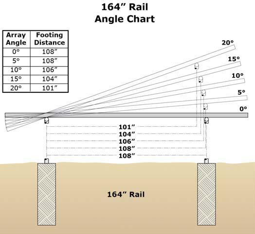
2 Installation steps overview 1) Dig footings 5) Insert pipe and center 2) Assemble re-usable grade stake forms 6) Fasten Drop-N-Lock / U-bolt 3) Insert grade stakes / lay pipe & tees Assembly 4) Measure & cut vertical pipes 7) Attach rail spacers every 10 8) Pour concrete 9) Remove re-usable stakes and install solar modules 10) Completed installation Step 1: Dig footings Dig footings. Lateral footing spans listed on page 6. Front to rear footing spans listed in angle charts on page 6. See engineering for general footing specifications. (Footing depths may vary depending on site specific conditions such as sloped hillsides. Review site specific requirements with local building department as necessary.) To speed up installation it is recommended to use a 12 power auger to dig your footings. Step 2: Build grade stake forms Assemble re-usable ProSolar grade stakes). Recommend 2 x4 vertical support. Drill 2 x 4 with 1/2 drill bit using grade stake as hole template. Assemble bolt, washer, spacer block and grade stake and tighten using 9/16 socket. Attach 1 x 4 wooden horizontal support using 3-1/2 (min.) C-clamps. Grade stake kit incudes: 24 threaded metal stakes, aluminum spacer blocks, bolts and washers. Step 3: Insert grade stakes and lay horizontal pipe support Drive grade stakes with sledgehammer beside each footing and level 1 x 4 supports using string line/line level or laser level. Place horizontal 1-1/2 schedule 40 galvanized pipe with slip-on Hollaender Tees along 1 x 4 supports. Adjust C-clamps as necessary to level pipe. Use pipe wrenches to couple pipe lengths as necessary. Page 2 of 7

 for your supports. Standard 21 length water pipe with pre-attached couplers readily available at plumbing supply houses.")


3 Step 4: Measure pipe heights and cut Measure vertical pipe lengths with measuring tape from bottom of footing to horizontal pipe. Deduct 2 from length to avoid pipe contact with bottom of footing moisture. Note measured lengths. Cut pipe lengths using a chop saw, reciprocating saw, or portable band saw Use only 1-1/2 Schedule #40 Galvanized water pipe (not fence tube) for your supports. Standard 21 length water pipe with pre-attached couplers readily available at plumbing supply houses. Step 5: Insert vertical support pipes and center Insert vertical pipes into tees and fasten lower tee set screw with long-arm hex key. Center vertical pipes in footings by sliding left or right. 1-1/2 Schedule 40 pipe max end overhang of 2 feet. Step 6: Attach initial support rails with Drop-N-Lock U-bolt assembly Rest pre-slotted rail on top of horizontal pipes and insert U-bolt. Place Drop-N-Lock support rail insert into the rail and align with U-bolt. Hand tighten nuts. U-bolt nuts should be evenly tightened to avoid u-bolt misalignment. Drill rail locking holes with Irwin 10 (1/2 ) Unitbit Page 3 of 7

4 Step 7: Attach support rails (spacers) every 10 Install at least one rail approximately every 10 for proper pipe spacing. If not using slotted rail, see page 7 for drilling rail locking holes. GroundTrac Step 8: Pour concrete Pour or pump mixed concrete into footings. Let cure. Extruded edges of the aluminum can be sharp. Treat any sharp edges as necessary to prevent injury. Page 4 of 7


5 Step 9: Remove re-usable forms and install modules Remove grade stakes. Tighten all tee set screws, both upper and lower, to 17 ft-lbs with torque wrench and hex bit socket. Adjust initial rails to final location. Install remaining rails. Tighten all U-bolt nuts evenly with 1/2 socket or impact gun. Install solar modules with pre-assembled ProSolar clamping hardware. Install ProSolar EZ rail end caps with adhesive. Install 1-1/2 plastic pipe end caps for schedule 40 pipe as necessary. EZ rail endcap Install EZ rail end caps to button up system and cap any trimmed rail ends Install pipe end caps to cap off pipe ends Step 10: Completed GroundTrac Installation Completed GroundTrac Installation. Clamping hardware is engineered exclusively for Professional Solar Products support rail. Page 5 of 7


6 ** ** Page 6 of 7
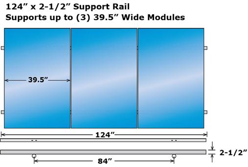
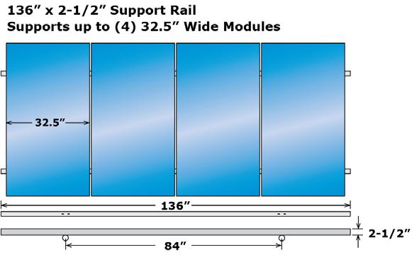
7 Step 11: Drilling holes for rails The 1/2 *(#10) Irwin Uni-Bit drill bit decreases rail locking hole drill time to 3 seconds. 41 INCHES 41 INCHES 1/2" "U-BOLT HOLES CENTER 2 INCHES If not using pre-slotted rails, use the 1/2 diameter Irwin Uni-Bit (#10) short nose drill bit to drill U-bolt assembly rail locking holes. 124 & 136 Support Rail Lengths (see page 6 for span illustration) Upper pipe to lower pipe span (distance between U-bolts): 84 on center U-bolt locking holes 41 from center (see above illustration) 164 Support Rail Length (see page 6 for span illustration) Upper pipe to lower pipe span (distance between U-bolts): 108 on center U-bolt locking holes 53 from center (not shown) Align several rails side by side, as shown. Using a square and Sharpie marker, mark hole locations along integrated rail bottom drill guide. Drill marked locations with cordless drill and Uni-Bit speed drill bit Page 7 of 7
8 Listing Constructional Data Report (CDR) 1.0 Reference and Address Report Number LAX-003 Original Issued: 14-Sep-2012 Revised: 28-Apr-2015 UL Subject Outline of Investigation Rack Mounting Systems and Clamping Devices for Standard(s) Flat-Plate Photovoltaic Modules and Panels. Issue #2: 2012/11/13 Applicant Address Country Contact Phone FAX Professional Solar Products, Inc S. Rose Avenue Oxnard, CA USA Stan Ullman (805) (805) s@prosolar.com Manufacturer Address Country Contact Phone FAX Professional Solar Products, Inc S. Rose Avenue Oxnard, CA USA Stan Ullman (805) (805) s@prosolar.com Page 1 of 63 ProSolar UL2703 Addendum <2 pgs>
9 Report No LAX-003 Professional Solar Products, Inc. Page 2 of 63 Issued: 14-Sep-2012 Revised: 28-Apr Product Description Product Brand name Photovoltaic Racking System ProSolar The product covered by this listing report is a rack mounting system. It is designed to be installed on a roof. It will be secured by means of Fast Jack or Tile Trac attachments, depending on the type of roof it is intended to be installed upon. The Rooftrac mounting system is comprised of support rails and top-down clamping hardware. This device can be used on most standard construction residential roof-tops. This system is in compliance with the mounting, bonding and grounding portions of UL Subject This system has the following fire class resistance ratings: Class A for Steep Slope Applications when using Type 1 or Type 2, Listed Photovoltaic Modules. Class A for Steep Slope Applications when using Type 2, Listed Photovoltaic Modules with or without the wind skirt. Class A for Low Slope Applications when using Type 1, Listed Photovoltaic Modules when a minimum of 12 gap between the roof surface and the bottom of the module is maintained. Class A for Low Slope Applications when using Type 2, Listed Photovoltaic Modules when a minimum of 14 gap between the roof surface and the bottom of the module is maintained. Description RoofTrac has different types of bonding and grounding, below is a list of them: Bonding of module-to-roof Trac rail via Weeb PMC Bonding of module-to-rooftrac rail via ProSolar rail channel nut using buss bar Bonding of module-to-roof Trac rail via Ilsco SGB-4 lugs Bonding of Roof Trac rail-to-roof Trac rail via Weeb Bonding Jumper-6.7 Bonding of Roof Trac rail-to-roof Trac rail via Ilsco SGB-4 Lugs Bonding of RoofTrac rail-to-rooftrac rail via ProSolar UL 467 tested universal splice kit (Splice Insert and Splice Support) Models Model Similarity Ratings Other Ratings Issuance of this report is based on testing to PV module frames with a height of 1 1/4 inch to 2 inches The grounding of the entire system is intended to be in accordance with the latest edition of the National Electrical Code, including NEC 250: Grounding and Bonding, and NEC 690: Solar Photovoltaic Systems. Any local electrical codes must be adhered in addition to the national electrical codes. This product investigation was performed only with respect to specific properties, a limited range of hazards, or suitability for use under limited or special conditions. The following risks and other properties of this product have not been evaluated: electric shock, Ultraviolet light exposure. RoofTrac N/A Fuse rating: 20 A Mechanical Load: 30 PSF Fire Class Resistance Rating: Class A for Steep Slope Applications when using Type 1 and Type 2, Listed Photovoltaic Modules. Class A for Low Slope Applications when using Type 1 and Type 2, Listed Photovoltaic Modules Mechanical load was tested using 60 Cell Canadian Solar Modules model CS6P with 40mm frame height and maximum span of 48 inches using 4 inch and 6 inch TileTrac or FastJack posts with 1-1/2 inch tall RoofTrac rail. And maximum span of 72 inches using 4 inch and 6 inch TileTrac or FastJack with 2-1/2 inch tall RoofTrac rail. ProSolar UL2703 Addendum <2 pgs> ED (1-Jan-13) Mandatory
PV Mounting System 2703 SERIES 200 UL GROUND MOUNT SYSTEM. SnapNrack Residential PV Mounting Systems Code Compliant Installation Manual
 PV Mounting System 2703 SERIES 200 UL GROUND MOUNT SYSTEM SnapNrack Residential PV Mounting Systems Code Compliant Installation Manual Series 200 UL Introduction Series 200 UL Introduction SnapNrack Series
Mounting systems for solar technology
 Mounting systems for solar technology ASSEMBLY INSTRUCTIONS CROSSRAIL TILT KIT 7 / 0 / 5 TILT FOR LOW-SLOPE AND STEEP-SLOPE ROOFS TABLE OF CONTENTS TABLE OF CONTENTS THE COMPANY SAFETY REGULATIONS MATERIALS
ASSEMBLY INSTRUCTIONS RESIDENTIAL SOLUTION CROSSRAIL GROUND MOUNT SYSTEM USA
 ASSEMBLY INSTRUCTIONS RESIDENTIAL SOLUTION CROSSRAIL GROUND MOUNT SYSTEM USA TABLE OF CONTENTS TABLE OF CONTENTS SAFETY REGULATIONS MATERIALS REQUIRED ASSEMBLY ENGINEERING DRAWINGS TERMS AND CONDITIONS
V I N C I & A S S O C I A T E S Structural Engineers
 CLIENT: Professional Solar Products, Inc. (ProSolar) 1551 S. Rose Ave., Oxnard, CA 93033 Tel: 805-486-4700 V I N C I & A S S O C I A T E S Structural Engineers Subject: Static load test results for the
Washer, Electrical Equipment Bond. WEEB Patent Pending INSTALLATION INSTRUCTIONS. For POWER-STRUT Mounting System only
 Washer, Electrical Equipment Bond WEEB Patent Pending INSTALLATION INSTRUCTIONS For POWER-STRUT Mounting System only Please read carefully before installing. Burndy LLC recommends that the sufficient details
For Silverback Solar
 Washer, Electrical Equipment Bond WEEB Patent Pending INSTALLATION INSTRUCTIONS For Silverback Solar Please read carefully before installing. Wiley Electronics recommends that the sufficient details of
SWH Solar Racking Ground Mount Installation Guide
 Version 16.02.v1 SWH Solar Racking Ground Mount Installation Guide Installer responsibility The installer is solely responsible for: Complying with all local or national building codes, including any that
GROUND MOUNT INSTALLATION MANUAL
 GROUND MOUNT INSTALLATION MANUAL Contents DISCLAIMER 1 CHECKLIST 2 1. ERECT BASe 3 2. CONNECT PIPES 3 3. PLACE RAILS 4 4. SECURE LUGS 4 5. CLAMP MODULES 5 DIAGONAL BRACES (OPTIONAL) 6 UNDER CLAMPS (OPTIONAL)
PRR. Flush Mount Racking System. Installation Manual
 PRR Flush Mount Racking System Installation Manual Release, September 2014 Table of Contents 1. Introduction 1.1 Product Overview 1.2 About This Manual 1.3 Product Liability 1.4 Standards Compliance 1.5
For HatiCon Solar Mounting System only
 Washer, Electrical Equipment Bond WEEB Patent Pending INSTALLATION INSTRUCTIONS For HatiCon Solar Mounting System only Please read carefully before installing. Burndy LLC. recommends that the sufficient
Aurora Genmounts Install LT Installation Manual
 Aurora Genmounts Install LT Installation Manual TABLE OF CONTENTS 1.0 INTRODUCTION 2.0 PRODUCT OVERVIEW 3.0 TECHNICAL SPECS 4.0 INSTALLER RESPONSIBILITY 5.0 SITE SELECTION 6.0 TOOLS REQUIRED 7.0 COMPONENT
INSTRUCTIONS FOR ASSEMBLING NEBS FLOODED RACKS
 INSTRUCTIONS FOR ASSEMBLING NEBS FLOODED RACKS Publication No. US-NEBS-IM-003 September 2013 INSTRUCTIONS for ASSEMBLING NEBS FLOODED RACKS Read all instructions carefully and observe all warnings before
ASSEMBLY INSTRUCTIONS COMMERCIAL ROOF SOLUTIONS D DOME RAILLESS 2 SYSTEM. UL 2703 Listed System USA
 ASSEMBLY INSTRUCTIONS COMMERCIAL ROOF SOLUTIONS D DOME RAILLESS 2 SYSTEM UL 2703 Listed System USA TABLE OF CONTENTS TABLE OF CONTENTS SAFETY REGULATIONS MATERIALS REQUIRED BONDING AND GROUNDING FIRE RATING
SnapNrackTM GROUND MOUNT CODE COMPLIANT INSTALLATION MANUAL
 SnapNrackTM PV MOUNTING SYSTEM GROUND MOUNT CODE COMPLIANT INSTALLATION MANUAL Table of Contents 1. INTRODUCTION...2 1.1 Overview of the Ground Mount System...2 1.2 Overview of this manual...3 1.3 Your
ROOF MOUNT KIT OWNERS MANUAL
 ROOF MOUNT KIT OWNERS MANUAL Made in the USA by: Southwest Windpower, Inc. 1801 W. Route 66 Flagstaff, Arizona 86001 Phone: (928) 779-9463 Fax: (928) 779-1485 E-mail: info@windenergy.com Web: www.windenergy.com
Stealth Residential Roof Mount System Installation Manual
 www.pvracking.com Stealth Residential Roof Mount System Installation Manual 2703 Listed PV Mounting System Table of Contents OVERVIEW OF COMPONENTS... 3 COMPONENTS... 3 OVERVIEW... 6 PV STEALTH ROOF INSTALLATION...
INSTALLATION GUIDE Sika SolarMount 1 Exposition East West
 Exposition East West CONTENTS 1 Notes on the Sika SolarMount 1 system (Exposition East West) for PV solar arrays 3 2 Setting up on site 3 3 Required Tools for mounting Sika SolarMount 1 to Sika roofing
Universal Elevator Mount Owners Manual
 REQUIRED TOOLS AND MATERIALS: 2 Capable Adults Universal Elevator Mount Owners Manual 1-00-spalding Carpenter s Level 15 Tape Measure Pencil Adult Assembly Required. This manual, accompanied by sales receipt,
ROOF MOUNT KIT OWNERS MANUAL
 ROOF MOUNT KIT OWNERS MANUAL Made in the USA by: Primus Wind Power, Inc. 938 Quail St. Lakewood, CO 80215 Phone: (303) 242-5820 www.primuswindpower.com AIR is a trademark of Primus Wind Power, Inc. ROOF
ZS880 Linear Shower Drain Installation Instructions
 Introduction PATENT PENDING The Zurn ZS880 Stainless Steel Linear Shower Drain incorporates a simple approach to bathroom shower design, when compared to traditional point-drain applications. The linear
The Racking System Designed by Installers for Installers. PV Stealth Roof System Installation Instructions
 PV Stealth Roof System Installation Instructions Key Benefits: Available in Black or Mill finish. Modules can be seated without any bolts, clamps or clips. Module Hold Down Area is more than 10x that of
C.R. LAURENCE CO., INC. Intelli-Track SPS. Phase One - Installation Instructions
 Tools and Supplies: C.R. LAURENCE CO., INC. Intelli-Track SPS Phase One - Installation Instructions Ratchet Wrench with 4" Extension 9/16" Open-End Wrench (two required for suspension mounting) 9/16" Hex
PRODUCT INFORMATION Dero Hoop Rack
 PRODUCT INFORMATION Dero Hoop Rack 2946 Larimer St. Denver, CO 80205 303-295-1100 / 800-373-7693 FAX 303-295-2464 Email info@snyderequipment.com www.snyderequipment.com H O O P R A C K The Hoop Rack is
STP Mount Series. Installation Manual. STP-LSCR-MAN 2017 Edition v1.0. For models: STP-SCR/045 STP-SCR/060 STP-SCR/070 STP-LCR/090 STP-LCR/120
 Installation Manual STP-LSCR-MAN 2017 Edition v1.0 For models: STP-SCR/045 STP-SCR/060 STP-SCR/070 STP-LCR/090 STP-LCR/120 Table of Contents Introduction... 1 Customer Support... 1 Tools Required... 2
The Racking System Designed By Installers for Installers
 The Racking System Designed PV Racking Ground System Installation Instructions Key benefits: Easy installation. No clamps! No more straining to lean over and fasten bolts! Module installation time is far
Leveling Foot RB210. Leg Extender RLT66
 Landing for Right & Left Turn R342 ITEMS # 0254049, 0254061, 0254072, 0254076, 0016567, 0254099, 0254110, 0054116, 0254117, 0254126, 0254140, 0254150, 0254156 CUSTOM ACCESS RAMP SYSTEM MODELS # R100, R242,
moment Engineering + Design Warwick Avenue, Suite #C5 Fairfax, VA Phone: Web:
 CrossRail48SConnector RE: CrossRail48SConnectorEvaluation DesignReferenceDocuments MinimumDesignLoadsforBuildingsandOtherStructures 2010AluminumDesign MetalCurtainWallFasteners Overview Methods&DesignParameters
Modular Simplicity Dero
 B I K E H AV E N Modular Simplicity The Bike Haven bridges the gap between short and long term bike parking. The simple, modular canopy design makes it easy to create the bike shelter that fits your needs.
Conergy SolarFamulus II
 Conergy SolarFamulus II Installation manual www.conergy.com Table of Contents Table of Contents SolarFamulus II for universal use on flat roofs 1 Introduction 1 1.1 Short description 1 1.2 Intended use
SECURE. UNIVERSAL. MOUNTING. Tilt Kit Installation Manual
 SECURE. UNIVERSAL. MOUNTING Tilt Kit Installation Manual 1.0 INTRODUCTION... 3 2.0 KITS / PRODUCT RANGE... 4 2.1 Leg Kits... 4 2.2 Rail Kits... 4 3.0 PREPARATION FOR INSTALLATION... 5 3.1 Applications...
Benefits in Speed and Logistics using the RL System. snapnrack.com
 Benefits in Speed and Logistics using the RL System snapnrack.com Agenda About SnapNrack Overview of Residential Solar Mounting Systems Benefits of railless systems What you should look for in a railless
Unirac Code-Compliant Installation Manual
 Planning and Assembly Installer responsibility The installer is solely responsible for: Complying with all local or national building codes, including any that may supercede this manual. Ensuring that
Just Makes Cents... Per Watt. Compliance Report Composition L-Foot Kit State of California September 25th SOLARACK INC.
 Just Makes Cents... Per Watt Compliance Report Composition L-Foot Kit State of California September 25th 2017 5062 Lankershim Blvd Suite # 418 North Hollywood, CA 91601 RE: Sunstrong Structural Compliance
VERsacourt LED Light System Installation Instructions
 VERsacourt LED Light System Installation Instructions PART LIST TEE BAR ASSEMBLY 10 12 LIGHT ASSEMBLY (hardware included) EXTENSION COLLAR BASE POLE EXTENSION POLE ANCHOR PAGE 1 REQUIRED TOOLS AND MATERIALS
Heartland Perma-Column 1841 E 1450 Rd. Lawrence, KS (785)
") Perma-Column Installation Instructions Unlike any other concrete post-frame foundation system, Perma-Column Precast Concrete Piers use 10,000 psi concrete and our unique Sturdi-Wall Plus wet-set bracket
Perma-Column Installation Instructions Unlike any other concrete post-frame foundation system, Perma-Column Precast Concrete Piers use 10,000 psi concrete and our unique Sturdi-Wall Plus wet-set bracket
Code Compliance Research Report CCRR-0238
 Code Compliance Research Report CCRR-0238 Issue Date: 11-09-2016 Revision Date: 11-29-2018 Renewal Date: 11-09-2019 DIVISION: 05 00 00 METALS Section: 05 52 00 Metal Railings CPG Building Products LLC
Rack-in-a-BoxTM INSTALLATION MANUAL
 INSTALLATION MANUAL TM 1.0 INTRODUCTION 3 2.0 PRODUCT RANGE 4 2.1 Systems 4 2.2 Accessories 4 3.0 PREPARATION FOR INSTALLATION 5 3.1 Applications 5 3.2 Tools for Installation 5 3.3 Additional Materials
PRU-D INSTALLATION MANUAL MONO-LEG SYSTEM. PRU-D / Portrait - Revision B July 31 st, 2017 Polar Racking Inc.
 PRU-D INSTLLTION MNUL MONO-LEG SYSTEM Table of Contents Table of Contents... 2 1. Safety... 3 Basic Safety Considerations... 3 Warnings and Symbols... 3 Responsibilities of the Installer... 3 Responsibilities
Radiant PV-RoofTopRac System Planning and Installation With Australia AS/NZS1170.2:2011 AMDT
 Radiant PV-RoofTopRac System Planning and Installation With Australia AS/NZS1170.2:2011 AMDT 2-2012 The PV-RoofTopRac System has been developed as a universal system for roof-mounting on pitched roofs.
Installation Instructions
 Installation Instructions Dynarail Safety Ladder System Corrosion Resistant Nonconductive Fire Retardant High Strength-To-Weight Ratio Long, Low Maintenance Life Meets OSHA, BOCA & Other Building Code
Code Compliance Research Report CCRR-0238
 Code Compliance Research Report CCRR-0238 Issued: 11-09-2016 Renewal Due: 11-09-2018 Revised: 11-10-2017 DIVISION: 05 00 00 METALS Section: 05 52 00 Metal Railings CPG Building Products LLC 894 Prairie
INSTALLATION GUIDE REV2016NOV15 DOCUMENT REVISION HISTORY - INTERNAL USE ONLY - NOT FOR PUBLIC RELEASE REVISED EQUATIONS - PAGE 1 - ADDITIONAL CHANGES
 INSTALLATION GUIDE DOCUMENT REVISION HISTORY - INTERNAL USE ONLY - NOT FOR PUBLIC RELEASE REVISION DATE 2016MAY31 2016OCT17 2016NOV15 Notes / Changes INITIAL RELEASE REVISED EQUATIONS REVISED EQUATIONS
Code Compliance Research Report CCRR-0187
 Code Compliance Research Report CCRR-0187 Issue Date: 11-29-2012 Revision Date: 07-24-2018 Renewal Date: 02-28-2019 DIVISION: 06 00 00 WOOD, PLASTICS AND COMPOSITES Section: 06 63 00 Plastic Railings REPORT
PanelGrip Dry Glaze Glass Railing System
 Metric Version PanelGrip Dry Glaze Glass Railing System Patent Pending Nationwide supplier of trims, mouldings and components for the glass and mirror industry. Reduces Labor Costs up to 80% Reduces Freight
A Collaborative Program of Arbor Day Foundation and Dimensions Educational Research Foundation. Tube Drums #7000. Assembly Instructions
 A Collaborative Program of Arbor Day Foundation and Dimensions Educational Research Foundation Tube Drums #7000 Assembly Instructions Please open and inspect all items upon receipt. If you have any questions
TFX - Toggle Lock Installation Guide
 Trench Former Pre-Engineered Cast In Place Trench Drain Forming System TFX - Toggle Lock Installation Guide P.O. Box 837-259 Murdock Road - Troutman, NC 28166 Tel (704) 528-9806 - Fax (704) 528-5478 -
Installation Guide EcoFoot5D High Density 5-Degree Ballasted Racking System Document No. ES10560
 Installation Guide Installation Guide EcoFoot5D High Density 5-Degree Ballasted Racking System Document No. ES10560 Rev 1.0, September 2017 Sales: 740-249-1877 Sales@EcolibriumSolar.com Field Support:
TILT-UP LIFTING PRODUCTS
 TILT-UP LIFTING PRODUCTS 37 Super-Lift www.meadowburke.com 877-518-7665 STRONGBACKS When will they be needed? A. If a panel looks like it would fall over when standing up. The strongback acts as a crutch
ASSEMBLY INSTRUCTIONS for DATASAFE TM HX and HX FRONT TERMINAL UBC BATTERY RACKS
 US-HXRACK-IM-002 ASSEMBLY INSTRUCTIONS for DATASAFE TM HX and HX FRONT TERMINAL UBC BATTERY RACKS Read all instructions carefully and observe all warnings before installation. See Installation, Operation
A. Division 01: Administrative, procedural, and temporary work requirements apply to this section.
 Copyright 2016 Metal Roof Innovations, Ltd. www.s-5.com SECTION 26 31 00.01 PHOTOVOLTAIC COLLECTOR ATTACHMENT SYSTEM PART 1 - GENERAL 1.1 SUMMARY A. Section Includes: 1. Photovoltaic Collector Attachment
INSTALLATION MANUAL. All Types F Series Rev G
 INSTALLATION MANUAL All Types - 1570 F Series Page 1 of 16 TABLE OF CONTENTS DESCRIPTION PAGE GENERAL INFORMATION & ADVISORIES 2 PRODUCT INFORMATION 3 GET TO KNOW YOUR CBU 4 HARDWARE AND COMPONENTS 5 CONCRETE
DPA Solar Racking Solutions Ground Mount Installation Guide V1.5
 DPA Solar Racking Solutions Ground Mount Installation Guide V1.5 Introduction It is important to note that the installer is responsible for the following: Complying with all applicable local or national
ROAD CLOSURE GATE PLAN ESTIMATED QUANTITIES CONCRETE FOOTINGS FOR S. D. DEPT. OF TRANSPORTATION DECEMBER 1996 ELEVATION CABLE TIE DOWN FOOTING
 ADMIN. S 1 1 13 199 POST Anchor Bolts (4 Required) 1 Pole Base Plate Footing PLAN POST Chamfer on Footing ESTIMATED QUANTITIES ITEM UNIT QUANTITY Footing & Eyebolt Class M5 Concrete CU.YD. 0.5 The quantity
SunModo PV Rack Mounting System UL2703 Compliant
 SunModo PV Rack Mounting System UL2703 Compliant Pub. D10100-V003 Copyright 2017 1 of 29 Please read carefully before installing Product is tested to and recognized to UL 2703 standards for safety grounding
H 12 Heavy Duty Modern Tripod 8 Seat Swing Heavy Duty Hangers
 Page 1 IMPORTANT Please retain this instruction sheet in your files. It contains important replacement parts information. All equipment should be installed in accordance with these instructions. It is
Installation Guide EcoFoot2+ 10-Degree Ballasted Racking System Document No. ECO-002_850. Rev 1.6, January 2018
 Installation Guide EcoFoot2+ 10-Degree Ballasted Racking System Document No. ECO-002_850 Rev 1.6, January 2018 Sales: 740-249-1877 Sales@EcolibriumSolar.com Field Support: 866-488-6794 FieldSupport@EcolibriumSolar.com
Fig Beam Clamp Retaining Strap (B-Line B3367)
") Fig. 69 - Beam Clamp Retaining Strap (B-Line B3367) Size Range: 3 /8"-16 thru 3 /4"-10 rod 4 (101.6mm) thru 16 (406.4mm) lengths Note: longer lengths are available consult factory Material: Pre-Galvanized
Fig. 69 - Beam Clamp Retaining Strap (B-Line B3367) Size Range: 3 /8"-16 thru 3 /4"-10 rod 4 (101.6mm) thru 16 (406.4mm) lengths Note: longer lengths are available consult factory Material: Pre-Galvanized
STRUCTURAL REPORT. Magerack Series 101 PV Mounting System. 130 mph Wind, Exposure B & C. California DESIGNER OF RECORD
 STRUCTURAL REPORT Magerack Series 101 PV Mounting System 130 mph Wind, Exposure B & C California DESIGNER OF RECORD Magerack Corporation 4453 Enterprise Street Fremont, CA 94538 Date: January 1, 2015 S
Revision Date: April 01, Premier Vinyl Enclosure
 Premier Vinyl Enclosure www.urbanindustries.com 53 Urban Industries, Inc. 2008 Tools The following tools are recommended for the installation of the Premier Vinyl Enclosure and roof. 1 2 Level 1 4 Level
Code Compliance Research Report CCRR-0118
 Code Compliance Research Report CCRR-0118 Issue Date: 12-15-2009 Revision Date: 04-30-2018 Renewal Date: 04-15-2019 DIVISION: 06 00 00 WOOD, PLASTIC, AND COMPOSITES Section: 06 63 00 - Plastic Railings
INSTALLING A POUR-IN-PLACE DOCK LEVELER (EH & RR)
") INSTALLING A POUR-IN-PLACE DOCK LEVELER (EH & RR) Part A: Prepare the Site & Make the Floor 1.) Prepare (concrete) dock wall and pit floor as shown in the diagrams. Pit floor should taper from back to
INSTALLING A POUR-IN-PLACE DOCK LEVELER (EH & RR) Part A: Prepare the Site & Make the Floor 1.) Prepare (concrete) dock wall and pit floor as shown in the diagrams. Pit floor should taper from back to
SECTION DUALGARD SNOW GUARDS
 Copyright 2016 Metal Roof Innovations, Ltd. www.s-5.com SECTION 07 72 53 DUALGARD SNOW GUARDS This section has been prepared by Metal Roof Innovations, Ltd. for use in the preparation of a project specification.
On-roof system Tau Installation manual
 On-roof system Tau Installation manual 810-0052 Table of Contents 1 Introduction 1 1.1 Short description 1 1.2 Intended use 1 1.3 Standards and guidelines 1 1.4 About these instructions 1 Tau The innovative
Structural Cantilever Installation Manual
 Structural Cantilever Installation Manual 944 Fisher St. Houston, TX 77018 ~ 713-957-1111 Table of Contents Assembly... 3 Warnings... 3 Tools... 3 Components... 4 Begin Assembly... 5 Step #1: Check all
Quick Adjustable Height Stands
 Quick Adjustable Height Stands Installation, Maintenance & Parts Manual DORNER MFG. CORP. INSIDE THE USA OUTSIDE THE USA P.O. Box 0 975 Cottonwood Ave. TEL: -800-397-8664 TEL: 6-367-7600 Hartland, WI 5309-000
Clenergy ezrack SolarRoof Code-Compliant Planning and Installation With Australia AS/NZS1170
 Clenergy ezrack SolarRoof Code-Compliant Planning and Installation With Australia AS/NZS1170 The ezrack has been developed as a universal system for roof-mounting on pitched roofs. The use of patented
EASY RIDER (MUSTANG) EASY RIDER (PONY) EASY RIDER (ZEBRA) EASY RIDER (BRONCO)
 EASY RIDER (PONY) EASY RIDER (ZEBRA) EASY RIDER (BRONCO)") Page 1 * IMPORTANT * PLEASE RETAIN THIS INSTRUCTION SHEET IN YOUR FILES. IT CONTAINS IMPORTANT REPLACEMENT PARTS INFORMATION. ALL EQUIPMENT SHOULD BE INSTALLED IN ACCORDANCE WITH THESE INSTRUCTIONS. IT
Page 1 * IMPORTANT * PLEASE RETAIN THIS INSTRUCTION SHEET IN YOUR FILES. IT CONTAINS IMPORTANT REPLACEMENT PARTS INFORMATION. ALL EQUIPMENT SHOULD BE INSTALLED IN ACCORDANCE WITH THESE INSTRUCTIONS. IT
FitTech UP166F CHEST PRESS (FOOTING) UP166I CHEST PREES (IN GROUND) UP166S CHEST PRESS (SURFACE)
 UP166I CHEST PREES (IN GROUND) UP166S CHEST PRESS (SURFACE)") CHEST PRESS BASE COVER DESCRIPTION FOOTBUCK WELD ASSEMBLY HARDWARE COMPLETE HARDWARE COMPLETE HARDWARE COMPLETE /" ANCHOR ROD 3/" x " HEX HEAD CAP SCREW 3/" WEDGE ANCHOR 3/" ANCHOR BOLT 3/" FLATWASHER
CHEST PRESS BASE COVER DESCRIPTION FOOTBUCK WELD ASSEMBLY HARDWARE COMPLETE HARDWARE COMPLETE HARDWARE COMPLETE /" ANCHOR ROD 3/" x " HEX HEAD CAP SCREW 3/" WEDGE ANCHOR 3/" ANCHOR BOLT 3/" FLATWASHER
Code Compliance Research Report CCRR-0194
 Code Compliance Research Report CCRR-0194 Issued: 09-16-2013 Renewal Due: 09-16-2018 Revised: 10-12-2017 DIVISION: 06 00 00 WOOD, PLASTICS AND COMPOSITES Section: 06 05 23 Wood, Plastic, and Composite
PLEASE READ ENTIRE INSTRUCTION MANUAL BEFORE PROCEEDING!
 INSTALLATION GUIDE This guide is intended to aide in the installation of Dura-Trench systems. There are many different applications and situations for the use of this product and the installation procedures
Inigo Console Table INSTALLATION INSTRUCTIONS P74300, P A Page 1 of 5
 P74300, P74301 Page 1 of 5 THANK YOU FOR CHOOSING KALLISTA We appreciate your commitment to Kallista quality products. Please take a moment to review this manual before you install your Kallista product.
TABLE OF CONTENTS (CONT):
:") TABLE OF CONTENTS: Tools & Specifications System Components System Level Fire Code Compliance Locate Array & Place Bays Place Ballast Place Modules & Attach Clamps Attach Clamps Module Installation & Wire
TABLE OF CONTENTS: Tools & Specifications System Components System Level Fire Code Compliance Locate Array & Place Bays Place Ballast Place Modules & Attach Clamps Attach Clamps Module Installation & Wire
Mounting Screw. Channel Filler. Light Angle Adjustable Screw. LED Board Vertical stud and blocking Locking Nose. Driver.
 The Knife Edge Cove is a modular lighting system consisting of two parts: 1- An aluminum fixture housing extrusion 2- Drop-in lighting modules The fixture will provide a continuous knife edge architectural
SK3000 Structural Pallet Rack Installation and Assembly Manual
 SK3000 Structural Pallet Rack Installation and Assembly Manual Steel King Industries, Inc. 2700 Chamber St Stevens Pont, WI 54481 (800) 826 0203 www.steelking.com info@steelking.com ASSEMBLY INSTRUCTIONS:
PRODUCT INFORMATION Dero Rolling Racks
 PRODUCT INFORMATION Dero Rolling Racks 2946 Larimer St. Denver, CO 80205 303-295-1100 / 800-373-7693 FAX 303-295-2464 Email info@snyderequipment.com www.snyderequipment.com R O L L I N G R A C K The graceful
Zurn Z874. Trench Drain System. Installation Instructions
 Zurn Z874 Trench Drain System Installation Instructions Z874 Accessories Trench Drain System Below are the components of the Z874-X trench drain typical to an installation. Check your order to verify you
Zurn Z874. Trench Drain System. Installation Instructions
 Zurn Z874 Trench Drain System Installation Instructions Z874 Accessories Trench Drain System Below are the components of the Z874-X trench drain typical to an installation. Check your order to verify you
Instructions for 12 IGT system
 Instructions for 12 IGT system Step 1: IGT Site Preparation Site Location Several factors must be considered when choosing the site for your new In-Ground Trampoline (IGT) system. Since local soil and
A. Division 01: Administrative, procedural, and temporary work requirements apply to this section.
 Copyright 2015 Metal Roof Innovations, Ltd. www.s-5.com SECTION 07 72 53 COLORGARD SNOW GUARDS PART 1 - GENERAL 1.1 SUMMARY A. Section Includes: 1. Snow guards for metal roofs. 2. [Non-penetrating] [Face
ROLLING RACK. Simple Security
 Simple Security The graceful design and high security of the Rolling Rack has made this type of bike rack a standard for many schools and communities. The Rolling Rack can be used as a single-sided or
Zurn Z886. 6" Perma-Trench. Installation Instructions
 Zurn Z886 6" Perma-Trench Installation Instructions Z886 Accessories 6" [152mm] Wide Trench Drain System Below are the components of the Z886 trench drain typical to an installation. Check your order to
SECTION HANDRAILS AND RAILINGS. A. Section Metal Fabrications: Associated metal supports.
 SECTION 05520 HANDRAILS AND RAILINGS PART 1 GENERAL 1.1 SECTION INCLUDES A. Handrails and guardrails B. Guardrails for hatches and openings. C. Safety barriers. D. Roof edge protection. 1.2 RELATED SECTIONS
Smarter. Safer. Leaner.
 Smarter. Safer. Leaner. Fast Installation and Removal Decrease Leading Edge Exposure by 87% OSHA Compliant Versatile and Reusable Use Perimeter Protection Posts During Construction: At Building Perimeter
Typical Deck. CONSTRUCTION TIP SHEET 5 Basic Decks w/ 60 lb Live Loading
 CONSTRUCTION TIP SHEET 5 w/ 60 lb Live Loading April 1, 2017 This Tip Sheet reflects code requirements of the 2015 International Residential Code (IRC) with Washington State Amendments which update the
PATENTS ARE PENDING. Building Dimensions. Exterior Dimensions Roof Edge to Roof Edge
 Assembly Manual 8x5 PATENTS ARE PENDING Approximate Size 7980303 Storage Area Building Dimensions Exterior Dimensions Roof Edge to Roof Edge Interior Dimensions Wall to Wall Sq. Ft. Cu. Ft. Width Depth
SECTION ELEVATED BLEACHERS (Angle Frame Semi-Closed Deck)
") SECTION 13125 ELEVATED BLEACHERS (Angle Frame Semi-Closed Deck) PART 1 GENERAL 1.1 RELATED DOCUMENTS A. Drawings and general provisions of the Contract, including General and Supplementary Conditions and
SECTION 13125 ELEVATED BLEACHERS (Angle Frame Semi-Closed Deck) PART 1 GENERAL 1.1 RELATED DOCUMENTS A. Drawings and general provisions of the Contract, including General and Supplementary Conditions and
ITEM 555 CHAIN LINK FENCING
 ITEM 555 AFTER MARCH 1, 2012 CHAIN LINK FENCING 555.1 Description. This item shall govern for furnishing the quantities of chain link fencing and gates as shown on the plans, including all posts, bracing
Model # 338S-PR. 5/1/2014 Page 1 of 12
 Model # 338S-PR 5/1/2014 Page 1 of 12 /1/2014 Page 2 of 12 1675 Locust Street Red Bud, IL 62278 Phone: 618-282-8200 Fax: 618-282-8202 WARRANTY & TERMS WARRANTY: 5 Year Limited Warranty on Thermoplastic
6x5. Assembly Manual CAUTION. Sharp Edges PATENTS ARE PENDING. Building Dimensions. Approximate Size. Storage Area. Interior Dimensions
 Assembly Manual 6x5 PATENTS ARE PENDING Building Dimensions Approximate Size Storage Area Exterior Dimensions Interior Dimensions Roof Edge to Roof Edge Wall to Wall Sq. Ft. Cu. Ft. Width Depth Height
Installer Guide. Item
 Installer Guide Item 17392-01 Required tools and fixings Electric drill (non-impact setting) T-30 Torq bit (wedge type) 8mm hex socket Pozi head drill bit Tape measure Pencil/pen Hammer Tin snips Angle
EZ Standing Seam Roof Mounting System. SunModo PV Rack Mounting System UL2703 Compliant. 1 P a g e
 SunModo PV Rack UL2703 Compliant 1 P a g e Please read carefully before installing Product is tested to and recognized to UL 2703 standards for safety grounding and bonding equipment and meets UL 1703
Linear Drainage Z886. Perma-Trench. Installation Instructions. 100mm Clear Opening
 Linear Drainage Z886 100mm Clear Opening Perma-Trench Installation Instructions Z886 Tools Required Tape Measure Phillips Head Screwdriver Hammer Utility Knife Marker Cordless Drill Reciprocating Saw Ear
Model # 338S-P. 7/31/2012 Page 1 of 13
 Model # 338S-P 7/31/2012 Page 1 of 13 7/31/2012 Page 2 of 13 1675 Locust Street Red Bud, IL 62278 Phone: 618-282-8200 Fax: 618-282-8202 WARRANTY & TERMS WARRANTY: 5 Year Limited Warranty on Thermoplastic
Model # 358-R48. 7/7/2011 Page 1 of 11
 Model # 358-R48 7/7/2011 Page 1 of 11 7/7/2011 Page 2 of 11 1675 Locust Street Red Bud, IL 62278 Phone: 618-282-8200 Fax: 618-282-8202 WARRANTY & TERMS WARRANTY: 5 Year Limited Warranty on Thermoplastic
ROOF / GROUND MOUNTS
 ROOF / GROUND MOUNTS C O R P O R A T I O N DP&W Roof/Ground Mounts are available in several sizes and styles in both aluminum (AL) and painted steel (PS) versions. In addition to the standard configuration,
PATENTS ARE PENDING. Building Dimensions. Exterior Dimensions Roof Edge to Roof Edge
 Assembly Manual 8x9 PATENTS ARE PENDING Approximate Size 7640303 Storage Area Building Dimensions Exterior Dimensions Roof Edge to Roof Edge Interior Dimensions Wall to Wall Sq. Ft. Cu. Ft. Width Depth
EASY RIDER (MUSTANG) EASY RIDER (PONY) EASY RIDER (ZEBRA) EASY RIDER (BRONCO)
 EASY RIDER (PONY) EASY RIDER (ZEBRA) EASY RIDER (BRONCO)") Page 1 * IMPORTANT * PLEASE RETAIN THIS INSTRUCTION SHEET IN YOUR FILES. IT CONTAINS IMPORTANT REPLACEMENT PARTS INFORMATION. ALL EQUIPMENT SHOULD BE INSTALLED IN ACCORDANCE WITH THESE INSTRUCTIONS. IT
Page 1 * IMPORTANT * PLEASE RETAIN THIS INSTRUCTION SHEET IN YOUR FILES. IT CONTAINS IMPORTANT REPLACEMENT PARTS INFORMATION. ALL EQUIPMENT SHOULD BE INSTALLED IN ACCORDANCE WITH THESE INSTRUCTIONS. IT
OWNER S MANUAL SERIES MDS-96-BK, SM, DR
 SERIES MDS-96-BK, SM, DR OWNER S MANUAL Introduction... 1 Bill of Materials... 2 Assembly Instructions. 3 Warranty....12 IMPORTANT NOTES, WARNINGS AND SAFETY INSTRUCTIONS Ensure that all employees understand
SEISMIC PROTECTION SYSTEMS Bracing Products for Racks & Cabinets
 SEISMIC PROTECTION SYSTEMS Bracing Products for Racks & Cabinets Seismic Frame Two-Post Rack Page 11-3 Seismic Protection Products - Racks Page 11-6 Seismic Protection Products - Runway Page 11-8 Seismic
CITY OF FARGO SPECIFICATIONS SIGNING
 SIGNING PART 1 DESCRIPTION OF WORK The work to be done under this section of the Specifications and the accompanying plans consists of furnishing all labor, material and accessories necessary to complete