Contents. Foreword...iii Introduction...v Chapter 1: Tornado Profile... 1 Chapter 2: Effects of High Winds Chapter 3: Case Studies...
|
|
|
- Nigel Alexander
- 6 years ago
- Views:
Transcription
1
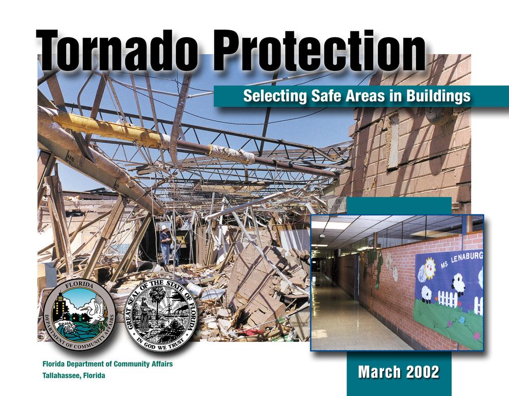
2 About the Cover The large photograph on the cover shows the remains of a central corridor in the Kelly Elementary School, in Moore, Oklahoma. The extreme damage shown was caused by one of the tornadoes that struck Oklahoma and Kansas on May 3, The corridor walls, which consisted of lightweight steel frame members with masonry infill topped by clerestory windows, were unable to withstand the extreme loads caused by lateral and uplift wind forces. As indicated by the inset photograph, which shows a similar corridor in another school, this type of corridor construction is common and creates special challenges for building administrators and design professionals who must identify areas of refuge in schools and other buildings.
3 Contents Contents Foreword...iii Introduction...v Chapter 1: Tornado Profile... 1 Chapter 2: Effects of High Winds... 7 Wind Effects on Buildings... 7 Atmospheric Pressure Changes... 8 Debris Impact... 9 Building Safe Spaces Chapter 3: Case Studies Xenia Senior High School St. Augustine Elementary School and Gymnasium St. Augustine Elementary School Building St. Augustine Elementary School Gymnasium Kelly Elementary School Florida Department of Community Affairs i
4 Contents Chapter 4: Selection Procedure Assess the Site Determine Required Amount of Shelter Space Review Construction Drawings and Inspect Building Example of Shelter Area Assessment General Architectural and Structural Characteristics Required Shelter Space Identifying the Most Resistant Areas Chapter 5: Conclusions Information Sources ii Tornado Protection: Selecting and Designing Safe Areas in Buildings
5 Foreword Foreword Tornadoes and extreme winds cause heavy loss of life and property damage throughout the United States. Most schools and other public buildings include areas that offer significant protection from this danger, and building administrators should know the locations of these areas. This booklet presents case studies of three schools that were struck by tornadoes: Xenia Senior High School in Xenia, Ohio; St. Augustine Elementary School in Kalamazoo, Michigan; and Kelly Elementary School in Moore, Oklahoma, which were struck on April 3, 1974; May 13, 1980; and May 3, 1999, respectively. The resulting damage to these schools was examined by teams of structural engineers, building scientists, engineering and architectural faculties, building administrators, and representatives of the architectural firms that designed the buildings. From these examinations, guidance has been developed for selecting the best available shelter areas in existing buildings. The guidance presented in this booklet is intended primarily to assist building administrators, but will also help architects and engineers design new buildings that are intended to offer protection from extreme winds. Building administrators, architects, and engineers are encouraged to apply this guidance so that the safety of building occupants will be increased. Florida Department of Community Affairs iii
6
7 Introduction Introduction The likelihood that a tornado will strike a building is a matter of probability. Tornado damage to buildings is predictable. Administrators of buildings should know where the safest places in their buildings are the portions that would offer protection if a tornado strikes. Most buildings offer a significant amount of protection for normal occupancy. A trained architect or engineer can determine those portions of a building that will offer the greatest protection to occupants when a tornado strikes. This conclusion is based on site examinations of, and research concerning, tornado damage to school buildings conducted by teams of structural engineers, architects, building scientists, and specially trained members of architectural and engineering faculties and firms. Architects and engineers should be able to use the information in this booklet to design buildings that offer higher levels of protection against high winds caused not only by tornadoes but also by hurricanes and other severe storms. The Wind Engineering Research Center at Texas Tech University provided much of the substance of this booklet. Dr. Kishor Mehta of the Center assisted in the preparation and review of the material. Invaluable assistance was provided by the architects and engineers of the buildings presented as case studies and by the school administrators. Florida Department of Community Affairs v
8
9 Chapter 1: Tornado Profile Tornado Profile The National Weather Service defines a tornado as a violently rotating column of air pendant from a thunderstorm cloud that touches the ground. From a local perspective, a tornado is the most destructive of all atmosphericgenerated phenomena. In an average year, a little more than 800 tornadoes hit various parts of the United States, though the number has varied from 500 to 1,400 in a given year. More tornadoes are recorded in the months of May and June than in any other month (Figure 1-1). Figure 1-2 shows the geographic distribution of tornadoes in the United States. Figure 1-1 States. Tornado occurrence by month in the United Tornadoes by Month JAN FEB MAR APR MAY JUN JUL AUG SEP OCT NOV DEC Florida Department of Community Affairs 1
10 Chapter 1: Tornado Profile TORNADO ACTIVITY IN THE UNITED STATES* Summary of Recorded F3, F4, and F5 Tornadoes Per 3,700 Square Miles ( ) Number of Recorded F3, F4, and F5 Tornadoes Per 3,700 Sq. Mi. 2 AMERICAN SAMOA, PUERTO RICO, VIRGIN ISLANDS Figure 1-2 HAWAII Tornado occurrence in the United States based on historical data. < > 25 * Based on NOAA Storm Prediction Center Statistics Tornado Protection: Selecting and Designing Safe Areas in Buildings
 The time of day when tornadoes are most likely to occur is the mid-afternoon, between 3:00 p.")


11 Chapter 1: Tornado Profile FEMA FEMA FEMA Tornado Characteristics TOTAL TORNADOES (PERCENT) Tornadoes Daily Occurrences 0 12 a.m. to 3 a.m. 3 a.m. 6 a.m. to to 6 a.m. 9 a.m. 9 a.m. 12 p.m. 3 p.m. 6 p.m. 9 p.m. to to to to to 12 p.m. 3 p.m. 6 p.m. 9 p.m. 12 a.m. HOUR SEGMENTS (3 HOURS) The time of day when tornadoes are most likely to occur is the mid-afternoon, between 3:00 p.m. and 6:00 p.m. (Figure 1-3). Occasionally, severe tornadoes have been recorded in the early morning or late evening. The direction of movement is predominantly from the southwest to the northeast. However, tornadoes have been known to move in any direction along with the parent thunderstorms. The length of path averages 5 miles, but some tornado paths have exceeded 100 miles. The width of path averages 300 to 400 yards, but may reach up to 1 mile. Figure 1-3 Tornado occurrence by time of day. The travel speed (translational) averages 25 to 40 miles per hour (mph), but speeds from 5 to 60 mph have been recorded. Florida Department of Community Affairs 3


12 Chapter 1: Tornado Profile F0 F1 F2 F3 F4 F5 F0 Light: Some damage can be seen to poorly maintained roofs. Unsecured lightweight objects, such as trash cans, are displaced. F1 Moderate: Minor damage to roofs occurs, and windows are broken. Larger and heavier objects become displaced. Minor damage to trees and landscaping can be observed. F2 Considerable: Roofs are damaged. Manufactured homes, on nonpermanent foundations, can be shifted off their foundations. Trees and landscaping either snap or are blown over. Medium-sized debris becomes airborne, damaging other structures. F3 Severe: Roofs and some walls, especially unreinforced masonry, are torn from structures. Small ancillary buildings are often destroyed. Manufactured homes on nonpermanent foundations can be overturned. Some trees are uprooted. F4 Devastating: Well constructed homes, as well as manufactured homes, are destroyed. Some structures are lifted off their foundations. Automobilesized debris is displaced and often tumbles. Trees are often uprooted and blown over. F5 Incredible: Strong frame houses and engineered buildings are lifted from their foundations or are significantly damaged or destroyed. Automobilesized debris is moved significant distances. Trees are uprooted and splintered. Figure 1-4 The Fujita Tornado Damage Scale. The rotational speed is assumed to be symmetrical. The maximum rotational velocity occurs at the edge of the tornado core. The speed reduces rapidly as the distance from the edge increases. F1 37% The intensity of damage from a tornado is related to wind speed, windborne debris, and type of construction. The atmospheric pressure drop in the center of a tornado does not destroy buildings, because pressures inside and outside of buildings equalize through broken windows and doors or through openings that result when sections of the roof are removed. F0 31% F3 7% F2 22% Tornadoes are rated by the National Weather Service according to the tornado damage scale developed by Dr. Theodore Fujita, a professor of meteorology. Ratings vary from F0, for light damage, to F5, for total destruction of a building (Figure 1-4). Ninety percent of the tornadoes recorded over the past 45 years have been categorized as F0, F1, or F2 (Figure 1-5). F5 F4 Less 2% than 1% Figure 1-5 Percentage of recorded tornadoes by Fujita Tornado Damage Scale ranking. 4 Tornado Protection: Selecting and Designing Safe Areas in Buildings


13 FEMA Chapter 1: Tornado Profile FEMA Rotation is generally counterclockwise in the northern hemisphere (Figure 1-6). About 10 percent of tornadoes have been known to rotate clockwise. Wind speed is the sum of rotational speed and translational speed. The rotational speed decreases as the distance from the center of a tornado increases. With a counterclockwise rotation, the wind speed on the right side of the tornado is higher because the translational speed adds to the rotational speed. N TORNADO TORNADO DIRECTION DIRECTION Because of the unpredictability of tornado paths and the destruction of commonly used instruments, direct measurements of wind speeds have not been made in tornadoes. Rather, wind speeds are judged from the intensity of damage to buildings. Engineering assessment of damage puts the maximum wind speed at 200 mph in most destructive tornadoes, and the speed is not likely to exceed 250 mph near ground level. Figure 1-6 Typical tornado rotation. Florida Department of Community Affairs 5
14
15 Chapter 2: Effects of High Winds Effects of High Winds In buildings hit by tornadoes, the threat to life is due to a combination of effects that occur at almost the same time. Tornado damage to buildings can occur as a result of the following: wind-induced forces changes in atmospheric pressure debris impact Wind Effects on Buildings The wind speeds generated by some tornadoes are so great that designing for these extreme winds is beyond the scope of building codes and engineering standards. Most buildings that have received some engineering attention, such as schools, and that are built in accordance with sound construction practices can usually withstand wind speeds specified by building codes. Meeting these code-specified wind speeds can provide sufficient resistance to tornadic winds if the building is located on the outer edge of the tornado vortex. In addition, if a portion of the building is built to a higher tornado design standard, then both building and occupant survival are improved. Wind creates inward- and outward-acting pressures on building surfaces, depending on the orientation of the surface (e.g., flat, vertical, low-slope). As the wind moves over the building, the outward-acting pressure increases as the building geometry forces the wind to change direction. These pressure increases create uplift on the building parts, forcing the building apart. When Florida Department of Community Affairs 7
16 Chapter 2: Effects of High Winds wind forces its way inside or creates an opening by breaking a window or penetrating the roof or walls, the pressures on the building increase even more. Figure 2-1 shows how wind affects both an enclosed building and a building with openings. Enclosed Building Building materials that have a better chance of surviving extreme winds are heavy (such as reinforced masonry or concrete) and are tied to all other building components with sound connections that resist the large uplift forces. Lightweight roofing materials such as gravel, wood, insulation, shingles, and even single-ply roofing membranes can be a problem. WIND DIRECTION Building shapes that catch the wind, such as overhangs, canopies, and eaves, tend to fail and become sails in extreme winds. Flat roofs can be lifted off when the wind flows over them and increases the uplift pressure at the corners and edges of the roofs. Atmospheric Pressure Changes The design of shelter space, either within a larger building or as a standalone structure, must consider the effect of a difference between the pressures inside and outside the building. The pressure outside a building during a tornado is very low compared to the pressure inside. In most buildings, there is enough air leakage through building component connections to equalize these pressures. WIND DIRECTION Partially Enclosed Building The explosion of buildings during a tornado due to atmospheric pressure differences is a myth. In reality, the combination of internal pressure and outward pull on the building from suction pressure has caused building failures that have forced the walls outward and given the building the appearance of having exploded. Doors and windows should remain closed on all sides of the building during an event in order to minimize the amount of wind that can enter the building. Figure 2-1 Effects of wind on a fully enclosed building and on a building with openings. FEMA 8 Tornado Protection: Selecting and Designing Safe Areas in Buildings
.")
17 Chapter 2: Effects of High Winds Figure 2-2 Example of damage from windborne missile. A 2-inch by 6-inch board penetrated a refrigerator. FEMA Debris Impact The extreme winds in tornadoes pick up and carry debris from damaged buildings and objects located in the path of the winds (see Figures 2-2 and 2-3). Even heavy, massive objects such as cars, tractor trailers, and buses can become windborne debris capable of causing collateral damage to buildings. Light objects become flying missiles that can penetrate doors, walls, and roofs; heavier objects usually roll and cause crushing-type damage. Figure 2-3 Example of damage from windborne missile. Metal door pushed inward by impact of heavy object. FEMA Missiles can travel vertically as well as horizontally (see Figure 2-4). For the safety of shelter occupants, protection must be provided overhead as well as on the sides of the shelter. Building walls and roofs can be designed to withstand the impacts of these missiles. Protection can be provided at the exterior building wall, or interior barriers can be constructed to provide protection for a smaller area within the building. Florida Department of Community Affairs 9

18 Chapter 2: Effects of High Winds Figure 2-4 Example of damage from windborne missile. Medium and small missiles penetrating through the roof of a high school. FEMA Building Safe Spaces Wind effects on buildings have been studied sufficiently to predict which building elements are most likely to successfully resist the extreme wind pressures caused by tornadoes and which are most likely to fail. Sufficient material testing and design work has been performed on large shelters to develop a shelter selection guide for any building intended for use as a shelter. Many buildings contain a smaller interior area or areas that could possibly be converted or reinforced for shelter use. The selection of shelter areas in buildings is discussed in Chapter Tornado Protection: Selecting and Designing Safe Areas in Buildings
19 Chapter 3: Case Studies Case Studies The three school buildings presented as case studies in this booklet were selected for the following reasons: All were hit by different, but intense storms. The three structures varied in size, age, and type of construction. All were relatively new structures at the time the tornadoes struck, designed by different architects and engineers to national building codes. All had to be partially or totally destroyed later because of the extent of the tornado damage. The building damage was examined by teams of structural engineers, building scientists, specially trained members of engineering and architectural faculties and firms, building administrators, and representatives of the architectural firms that designed the buildings. The determination of the best available shelter areas in the three buildings (shown on floor plans presented later in this chapter) was based on three sources of information, in the following order of importance: persons who were in each building during the tornado building examinations by engineers and architects aerial photographs taken shortly after the storms Florida Department of Community Affairs 11
20 Chapter 3: Case Studies The identified shelter areas in these buildings are the best that were available in each of the three buildings when the storms occurred. These case studies are presented here with two goals: to help building designers and administrators locate accurately the parts of a building that would be left standing after a tornado before the tornado strikes to help architects and engineers design buildings that offer occupants excellent tornado protection at little or no additional cost 12 Tornado Protection: Selecting and Designing Safe Areas in Buildings

21 Xenia Senior High School Xenia, Ohio Chapter 3: Case Studies Building population: 1,450, including staff 12 students, 3 staff in building during storm Tornado direction: From southwest Damage intensity: F5 Time: 4:45 p.m. Date: April 3, 1974 WERC, TEXAS TECH UNIVERSITY Figure 3-1 Xenia Senior High School, Xenia, Ohio. Florida Department of Community Affairs 13
22 Chapter 3: Case Studies Xenia Senior High School (Figure 3-1) was a two-story, slab-on-grade building without a basement located on the north side of Xenia, Ohio. It faced Shawnee Park to the west. The massive tornado hit 1 hour and 45 minutes after school dismissal. It was spotted by a student who was leaving the school. She alerted drama students who were rehearsing in the auditorium. The students ran and dove for shelter in a nearby corridor. The tornado passed directly over the school. Two school buses came to rest on the stage where the students had been rehearsing. Some of the students were treated for injuries at a nearby hospital. The building was found to be unsafe to enter and was demolished. Construction The construction types varied among the main parts of the school original building, three additions (A, B, and C): Original building and addition B: Lightweight steel frame, open-web steel joists, 2-inch gypsum roof deck. Addition A: Loadbearing masonry walls, hollow-core precast concrete roof planks. Addition C: Precast concrete frame, concrete double-tee floor/roof beams. Girls gym: Loadbearing masonry wall, precast concrete tee beams. Auditorium and boys gym: Loadbearing masonry walls, steel trusses. 14 Tornado Protection: Selecting and Designing Safe Areas in Buildings
. The enclosure walls failed on the west and south sides, allowing the winds to enter the building.")
23 Chapter 3: Case Studies ADDITION C ORIGINAL BUILDING ADDITION B ADDITION A Tornado Damage The tornado passed directly over the school, engulfing the entire building and the adjacent fieldhouse to the south (Figure 3-2). The enclosure walls failed on the west and south sides, allowing the winds to enter the building. The roofs collapsed over the three large spans the auditorium, the boys gym, and the girls gym. The lightweight roof over the original two-story building was torn off by the extreme winds. Figure 3-2 Xenia Senior High School, Xenia, Ohio. WERC, TEXAS TECH UNIVERSITY Florida Department of Community Affairs 15

24 Chapter 3: Case Studies Hazardous Elements All windows on the west and south sides were blown into the interior. The high single-story, loadbearing masonry walls of the long-span rooms failed, allowing the roofs to fall in. The unbaffled west entrances allowed the east-west corridors to become wind tunnels. Debris from nearby houses, vehicles, and Shawnee Park became missiles, many of which hit and entered the school. The 46-foot-high masonry chim ney collapsed. A non-loadbearing second-floor wall on the north side col lapsed onto a lower roof. Protective Elements The only portion of the original building that offered shelter was the lowest floor (first floor). The completely interior spaces remained intact, especially the smaller spaces. Most of the corridors that were perpendicular to the storm path offered considerable protection (Figures 3-3 and 3-4). The concrete structural frame of addition C remained intact. As a result, in terior portions of the second floor provided shelter for some custodians. The heavy concrete roof remained in place, wherever the supports were rigid frames. It also remained intact in addition A, with its loadbearing walls. The concrete block interior partitions stopped incoming missiles from reaching adjacent interior spaces. As a result of combinations of the above protective elements, extensive shelter space existed in scattered locations throughout the building (Figure 3-4). Figure 3-3 Surviving interior hallway. This is an example of the type of area that can provide refuge for building occupants during a tornado. WERC, TEXAS TECH UNIVERSITY 16 Tornado Protection: Selecting and Designing Safe Areas in Buildings
25 Chapter 3: Case Studies MECHANICAL FOOD ST. COOKING DRAFTING ROOM OFFICE GRAPHIC ARTS KITCHEN STO. D.R. SERVING CAFETERIA W M GIRLS' GYM C.R. LOCKERS ELECT LAB C.R. C.R. C.R. C.R. C.R. TEACH. CAFE. SHOWER MECH. WOOD SHOP C.R. LOCKERS C.R. BOYS' GYM WOOD SHOP OFFICES STO. C.R. BOILER RM. STO. STO. LOCKERS BUS. C.R. LOCKERS ART FOOD LAB FOOD PREP CAFETERIA SERV. LAB OPEN COURTYARD BUS. C.R. BUS. C.R. BUS. C.R. BUS. C.R. C.R. BUS. C.R. OFFICE LOBBY TEACH. CAFE. LIB. C.R. C.R. C.R. W W M C.R. C.R. C.R. C.R. C.R. OPEN COURTYARD CHORAL INST. MUSIC AUDITORIUM = SHELTER OFFICES STAGE C.R. C.R. C.R. OFFICE LOCKERS C.R. C.R. C.R. C.R. C.R. C.R. Xenia Senior High School Figure 3-4 Best available shelter areas in Xenia Senior High School. Florida Department of Community Affairs 17
26 Chapter 3: Case Studies Comments The cast had just done the big dance number from the show. They had done a sloppy job and I was just getting ready to tell them to do it again when a girl yelled, Hey, you want to see a tornado? There s a funnel cloud outside. I came very close to telling everyone to forget it and do the dance again. That would have been a fatal mistake. Instead, I jumped off the stage and told everyone to follow me so that we could get a view of it. We ran out the front doors of the school nearest the auditorium. It looked like a lot of dirt or smoke swirling around. We couldn t see anything that looked like a clearly defined funnel cloud. We were looking out at the park across from the school. The mass of wind, dirt, and debris was everywhere. I would say between 100 and 200 yards away. Cars parked in front of the school started to bounce around a bit from the force of the winds. It was really beyond belief. Someone said we d better take cover, so we turned around and ran from the hallway we were in into the center hall that ran north and south. Before we could reach the center hall, the lights went out. Figure 3-5 Loss of lightweight roof over the original two-story building. WERC, TEXAS TECH UNIVERSITY I only opened my eyes a couple of times. When I did, I saw large pieces of dirt and wood flying through the air. Lockers clanged open and shut, and several sections of lockers were actually pulled from the wall and thrown onto the floor. One section barely missed some of my students when it came out of the wall. I was sitting directly across from one of the restrooms, and a metal door kept flying open and shut constantly during the time that the tornado was on us. That was my greatest fear. English/Drama Teacher 18 Tornado Protection: Selecting and Designing Safe Areas in Buildings

27 Chapter 3: Case Studies I was watching the sky, and the lightning seemed to get worse. The minutes went by, and it at first had been going vertically, and slowly it started to go on angles. Figure 3-6 Collapsed hollow-core precast roof panels in the classroom area. WERC, TEXAS TECH UNIVERSITY The black cloud looked like it was about 2½ miles away from the school. As I watched, the lightning came concentrated into the middle of the cloud and began going on angles until it was horizontal. For a few seconds, I didn t know that the shrinking cloud was forming a tornado funnel. The funnel was a whitish-grey color more in the shape of a column than it was a funnel. I realized it was a tornado when I saw air currents begin to swirl. At first I was not afraid. Instead, I was fascinated that you could really see air currents in it. I went to the main office to get the principal, but the office was locked and everyone was gone. Just as I started to move, the drama cast started to rehearse a song in the auditorium I walked down the aisle past 24 rows of seats to one of my friends in the second row and said, Hi Paul, have you ever seen a tornado? He said Ya and put his arm up on the back of a chair like he s getting ready for a long conversation. I said Neat, there s one across the street. He looked up at me. Then they all stood up and started to walk out. They got about halfway out and started running. All the kids were yelling, Hey, neat, look at that and things like that. All of a sudden everyone was dead silent for about 4 seconds. Then everyone started screaming and yelling at once. Julie yelled, Get to A-1. I said, Get to the southwest corner. Mr. Heath turned around and yelled, Go to the main hall. So all the cast started to rush out of the doors and promptly got stuck, so they had to wait and go slow and go out one or two at a time. Student (spotter) Florida Department of Community Affairs 19

28 Chapter 3: Case Studies When we were warned about the tornado, we all ran to the door to look at it. I was about the last one to arrive there, and I stood there very long until someone yelled from around the corner to get over there. The last thing I saw the tornado doing was picking up my car which was parked out on the street. I then ran around the corner and found everyone already lying along each side of the wall and some around the corner. I then ran to the intersection of the two halls and laid alongside the wall. When it was all over, I was buried from the waist down in little pieces of gravel, boards, and a lot of water from the lake across the street in the park. Student The first place I ran to was this little cubbyhole right in front of the girls restroom door. If I had stayed there, I would have been splattered across the hall, because it blew so hard it almost came off its hinges. For some reason, which I cannot account for, I dived across the hall right after the lights went out and got to the other side of the hall just as the front doors were breaking. Figure 3-7 Collapsed gymnasium walls and roof, where open-web roof joists were supported on unreinforced masonry walls. WERC, TEXAS TECH UNIVERSITY I kept my eyes open, which was stupid on my part. I was looking down at the floor rather than out and I could see big chunks of wood and debris flying down the hall by my feet. It was incredible. Student 20 Tornado Protection: Selecting and Designing Safe Areas in Buildings

29 Chapter 3: Case Studies St. Augustine Elementary School and Gymnasium Kalamazoo, Michigan Building population: Approximately 400, including staff One staff person in the building during tornado Tornado direction: From west Damage intensity: F2-F3 Time: 4:09 p.m. Date: May 13, 1980 Figure 3-8 St. Augustine Elementary School, Kalamazoo, Michigan. WERC, TEXAS TECH UNIVERSITY Florida Department of Community Affairs 21

30 Chapter 3: Case Studies St. Augustine Elementary School Building The St. Augustine Elementary School was a two-story, 17-classroom building constructed in Classes had been dismissed when the tornado struck. Only the facility engineer remained in the building. He took shelter in a janitor s closet on the first floor and escaped injury. Construction The structural system consisted of 3-foot wide masonry piers of 8-inch concrete block and 4-inch face bricks. The piers were 8.7 feet apart. Steel beam lintels spanned the window openings between the piers. Steel open-web joists at 2 feet on center supported the 1.5-inch steel roof deck, which was welded to joists. The top chords of joists were extended to provide a 2-foot overhang. Tornado Damage The tornado winds lifted part of the roof and collapsed the second-floor piers in one wing of the school building (Figures 3-8, 3-9, and 3-10). The wind and windborne debris blew in most of the windows, and windborne debris was found in the classrooms (Figure 3-11). The exterior solid-core wood doors re mained in place and kept the debris out. Wired glass windows near the exte rior doors remained intact. The interior doors to the classrooms remained in place although the hinges were damaged. The school was damaged to an extent where demolition was required. Hazardous Elements The structural system of unreinforced masonry piers collapsed and almost one-third of the second-floor lightweight roof structure was lifted. Roof re moval occurred over the classrooms as well as over the corridor. Most of the skylights in the corridors were removed by wind or broken by windborne de bris. Almost all the windows on both floors were broken. Windborne debris Figure 3-9 Collapsed second floor of St. Augustine and broken glass were found in the classrooms. Elementary School building. WERC, TEXAS TECH UNIVERSITY 22 Tornado Protection: Selecting and Designing Safe Areas in Buildings

31 Chapter 3: Case Studies CR 203 STR 1 CR 201 St. Augustine Elementary School SECOND FLOOR PLAN = ROOF REMOVAL CR 204 COR 200 CR STO 215 OFF 216 TLT 127 CR 212 CR 210 CR 205 COR 123 Skylight STO 206 STR 2 STO 207 CR 208 Figure 3-10 Floor plan of second floor of St. Augustine Elementary School showing locations of roof removal. CR 209 STR 3 WERC, TEXAS TECH UNIVERSITY Figure 3-11 Broken windows and debris in classroom of St. Augustine Elementary School building. Florida Department of Community Affairs 23
32 Chapter 3: Case Studies Protective Elements The structural system of the first floor remained intact. The exterior solid- core wood doors remained in place and kept the debris out. The interior walls and doors were able to prevent debris from entering the corridors. The corridors, offices, and toilet areas on the first floor, which had two or more walls to the exterior, would have protected the occupants from serious injury (Figure 3-12). STR 1 CR 103 CR 101 St. Augustine Elementary School FIRST FLOOR PLAN = SHELTER CR 104 COR 100 CR CR TLT TLT COR CR OFF 118 OFF 120 OFF OFF T114 STR 2 CR 106 CR STR 3 Figure 3-12 Best available shelter areas in the St. Augustine Elementary School building. 24 Tornado Protection: Selecting and Designing Safe Areas in Buildings

33 St. Augustine Elementary School Gymnasium Chapter 3: Case Studies An 80-foot by 100-foot, 23-foot-high gymnasium building was adjacent to the school building. Construction The structural system consisted of loadbearing masonry walls of 12-inch concrete block and 4-inch face brick. The walls were not reinforced in the vertical direction. The roof structure consisted of long-span steel joists spanning 80 feet between the walls and spaced 6 feet apart. The corrugated steel roof deck was connected to joists with puddle welds. Figure 3-13 St. Augustine Elementary School Gymnasium, Kalamazoo, Michigan. WERC, TEXAS TECH UNIVERSITY Florida Department of Community Affairs 25

34 Chapter 3: Case Studies Tornado Damage The building was destroyed (Figures 3-13 and 3-14). The loadbearing west wall collapsed inward, and the east wall fell outward. The roof fell in the building when the walls collapsed. Hazardous Elements Slender unreinforced masonry walls and long-span roof structure. Protective Elements None Observations: School Building and Gymnasium The unreinforced masonry walls combined with the lightweight roof structure in the building as well as the gymnasium building were vulnerable to collapse in windstorms. Gymnasium buildings are not considered suitable for occupant protection because they usually include tall walls and longspan roofs. Lightweight roof structures that are not adequately anchored can be lifted in windstorms. The lower floor (in two-story or higher buildings) generally provides good protection for occupants when there are two or more walls between the shelter area and the outside. WERC, TEXAS TECH UNIVERSITY Figure 3-14 Collapsed St. Augustine Elementary School Gymnasium building. 26 Tornado Protection: Selecting and Designing Safe Areas in Buildings

35 Kelly Elementary School Moore, Oklahoma Chapter 3: Case Studies Building population: 490, including staff Tornado direction: Damage intensity: Time: Date: From southwest F4 7:25 p.m. May 3, 1999 Figure 3-15 Kelly Elementary School, Moore, Oklahoma. CLEVELAND COUNTY, OK Florida Department of Community Affairs 27
36 Chapter 3: Case Studies The Kelly Elementary School was a one-story slab-on-grade building, without a basement, located in Moore, Oklahoma. The tornado hit after school hours and passed just to the north of the site. Damage to the school building was both severe and extensive (Figure 3-15). As discussed in the Lessons Learned section in this case study, the remaining structure was demolished and the school was rebuilt. The new school includes structural elements designed to provide increased wind resistance. Construction Three basic wall types were used in the construction of the school: reinforced masonry unreinforced masonry topped by reinforced bond beams lightweight steel frame with masonry infill The roof system consisted of open-web steel roof joists, metal decking, and a built-up roof. Wall and roof construction of this type is common to many schools in the United States. Hall corridors were the designated areas of refuge (see Figure 3-16). The corridor walls were of lightweight steel frame with masonry infill. The infill extended to a height of approximately 7 feet. Above this height were clerestory windows that extended to the tops of the walls. 28 Tornado Protection: Selecting and Designing Safe Areas in Buildings
37 Chapter 3: Case Studies Original Kelly Elementary School Floor Plan SCALE: NOT TO SCALE = SHELTER N Figure 3-16 Designated shelter areas in the original Kelly Elementary School. Florida Department of Community Affairs 29

 from the upper part of a corridor wall.")
38 FEMA Chapter 3: Case Studies Tornado Damage Wall and roof structures, including those of designated areas of refuge, failed under the combination of uplift and lateral loads caused by the tornado winds. Connections between bond beams, joists, and walls were adequate for gravity loads, but could not resist the high uplift loads caused by the wind. Unreinforced masonry walls failed when the roof system was lifted or removed by tornado winds (Figures 3-17, 3-18, and 3-19). Figures 3-17 and 3-19 show failed interior and exterior walls, respectively. Figure 3-18 shows the separation of the reinforced bond beam (indicated by circles) from the upper part of a corridor wall. The inclusion of clerestory windows in some corridor walls contributed to their failure under loads imposed by tornado winds (Figure 3-20). Figure 3-18 Corridor area. Separation of reinforced bond beam (indicated by circles) from supporting wall. FEMA Figure 3-17 Interior and exterior unreinforced masonry walls were damaged when reinforced bond beams failed. 30 Tornado Protection: Selecting and Designing Safe Areas in Buildings


39 Chapter 3: Case Studies Figure 3-19 Collapsed roof structure and exterior wall. FEMA Figure 3-20 Failed interior corridor walls. These walls consisted of unreinforced brick masonry infill between steel-frame members. The brick masonry extended to a height of approximately 7 feet. Clerestory windows extended from the top of the masonry to the tops of the walls. FEMA Florida Department of Community Affairs 31
.")

40 Chapter 3: Case Studies Inspection of the roof damage revealed that the roof decking failed at the points where it was welded to the tops of the steel trusses. Although the spacing of the welds appeared to be consistent with standard practice, the welds were not strong enough to resist the wind uplift forces (Figure 3-21). Damage was also caused by the impact of windborne missiles. Figure 3-22 shows a steel door that appeared to have been opened by the impact of a heavy object. This door led into an area where the roof was missing. The opening created by this breached door may have allowed wind to enter the building and create internal pressure that increased the load on the building envelope. Figure 3-22 Damaged door pushed in by impact of heavy windborne debris. FEMA FEMA Figure 3-21 Failed roof structure showing broken welds between metal roof deck and tops of joists (upper circle) and lack of vertical reinforcement (bottom circle). 32 Tornado Protection: Selecting and Designing Safe Areas in Buildings
41 Chapter 3: Case Studies Hazardous Elements Walls with clerestory windows, such as the corridor walls of the designated areas of refuge, have limited capacity to resist lateral forces. Unreinforced masonry walls failed when the reinforced bond beams at the tops of the walls failed. Welds between the roof decking at the tops of the metal joists failed because they were not strong enough to resist uplift. Unprotected doors and windows can be breached by windborne missiles. The resulting openings allow wind to enter the building, where it causes increased pressures on the building envelope. Protective Elements None Lessons Learned Because the damage to Kelly Elementary School was so great, the school was demolished and completely rebuilt. The new building, although constructed on the same footprint, incorporated several structural improvements specifically designed to provide improved resistance to extreme winds and create shelter areas for the school s occupants. As in the original building, the central corridors of the three wings are the designated shelter areas (Figures 3-23 and 3-24). The creation of shelter areas in the new school involved, among other improvements, the design and construction of stronger loadbearing walls, roofs, roof-to-wall connections, and wall-to-foundation connections. Figure 3-25 is a typical cross-section of the top of a safe area (corridor) wall in the new school. As shown in this figure, the wall is constructed of reinforced concrete masonry. Note the continuous, closely spaced (8 inches on center) vertical reinforcement bars, fully grouted block cells, 6-inch-thick reinforced concrete Florida Department of Community Affairs 33
 in reconstructed Kelly Elementary School.")
42 CITY OF MOORE, OK Chapter 3: Case Studies New Kelly Elementary School Floor Plan SCALE: NOT TO SCALE N = SHELTER N Figure 3-23 Designated shelter areas in the reconstructed Kelly Elementary School. Figure 3-24 Corridor (designated safe area) in reconstructed Kelly Elementary School. 34 Tornado Protection: Selecting and Designing Safe Areas in Buildings
43 Chapter 3: Case Studies 2 1 /4-INCH FOAM INSULATION REINFORCING BARS AT 16 INCHES roof slab, and strong connection between the roof slab and wall. The new ceilings over the corridors are constructed of poured reinforced concrete, which will provide nearly ultimate resistance to winds and damaging missiles. SINGLE-PLY ON CENTER TIE Figure 3-26 is a typical cross-section of the bottom of a safe area wall. Note MEMBRANE (SPM) ROOF TO WALL 6-INCH LIGHTWEIGHT ROOFING that the wall is securely tied to the floor slab with L-shaped reinforcing bars POURED CONCRETE DECK WITH REINFORCING BARS placed 24 inches on center. As shown in Figures 3-23 and 3-24, the corridor AT 16 INCHES ON CENTER walls do not include the clerestory windows that increased the vulnerability of EACH WAY the corridor walls in the original school building. 1 1 /2-INCH METAL DECK CORRUGATED METAL FORM DECK The improvements discussed here are designed to prevent the types of damage to interior corridor walls and roofs shown previously in Figures 3-17, 3-18, 3-20, and The reconstruction of the Kelly Elementary School is a good example of how shelter areas can be incorporated into new construction. FULLY GROUTED TROUGH BLOCK WITH HORIZONTAL REINFORCING BARS OPEN-WEB STEEL JOISTS VERTICAL REINFORCING BARS IN GROUTED CELLS AT 8 INCHES ON CENTER CONTINUOUS TOP TO BOTTOM NEW CONCRETE SLAB FLOOR AND WALL TIED TOGETHER WITH BENT REINFORCING BARS SET IN ALTERNATING DIRECTIONS AT 24 INCHES ON CENTER ALONG ENTIRE PERIMETER OF WALL CLASSROOM SIDE CORRIDOR (SHELTER) SIDE EXISITING SLAB AND FOOTING Figure 3-25 Typical cross-section of top of safe area wall in the reconstructed Kelly Elementary School. Figure 3-26 Typical cross-section of bottom of safe area wall in the reconstructed Kelly Elementary School. Florida Department of Community Affairs 35
44
45 Chapter 4: Selection Procedure Selection Procedure The procedure presented in this chapter is designed to assist in a systematic review of a building for the purpose of selecting the areas within the building that are the most resistant to severe winds, referred to in this booklet as the most resistant areas available. When used as shelters during severe-wind events, these areas do not guarantee safety; they are, however, the safest areas available for the protection of building occupants. This selection procedure does not apply to structures such as lightweight modular houses and offices and relocatable classrooms. Such structures are presumed to fail, and they must be evacuated. Most buildings, unless specifically designed as shelters, will sustain catastrophic damage if they take a direct hit from a Violent Tornado (i.e., a tornado ranked F4 or F5 on the Fujita Tornado Damage Scale see Chapter 1). Because the maximum wind speeds associated with a Violent Tornado greatly exceed the wind speeds that the buildings were designed to withstand, complete destruction will usually occur during these extremely rare events. In reality, most tornadoes do not produce the winds of a Violent Tornado, and areas of many buildings can survive these lesser events without catastrophic damage or collapse. Placing building occupants in the most resistant areas available within a building greatly reduces the risk of death or injury. Florida Department of Community Affairs 37
46 Chapter 4: Selection Procedure Selecting the most resistant areas involves three main steps: assessing the surrounding site to identify potential windborne missiles or collapsible structures determining how much shelter space is required to house building occupants and determining where the shelter area(s) must be located to minimize the time required for people to reach shelter reviewing construction drawings and inspecting the building to identify the strongest portion(s) of the building Assessing the site and determining the required shelter space are relatively straightforward tasks that can be completed by many people. The drawing review and building inspections are more technical in nature. Structural engineers may need to be consulted for those tasks. Assess the Site Inspect the entire site and its surroundings to identify potential windborne missiles. The types and locations of potential missiles should be noted on a site plan that shows the building and its surroundings. (An example of a site plan is shown in the Assessment Example presented later in this chapter.) When identifying missile sources, keep in mind that stronger tornadoes create larger missiles. An F0 tornado can create missiles out of roof gravel, but it takes a much stronger storm to create missiles out of automobiles. Look for trash containers, air conditioning units, athletic field equipment, portable classrooms, storage sheds, parking areas, and anything else that can be picked up and carried by the wind. Check all roofs on the building and note any gravel ballast, vents, and roof-mounted equipment. Identify tall communication towers, chimneys, and trees that could topple under high winds. Keep in mind that, during stronger tornadoes, tall structures can not only topple but also be lifted and thrown by high winds. 38 Tornado Protection: Selecting and Designing Safe Areas in Buildings
47 Chapter 4: Selection Procedure While tornadoes can create strong winds from all directions, most move from the southwest to the northeast and have a diameter of 300 to 500 feet. Therefore, particular attention should be paid to identifying missile sources south and west of the building and within a 300- to 500-foot radius from the building. Often, potential missiles can be removed or secured to alleviate the risk of their becoming windborne. At a minimum, identifying potential missile sources will help identify the best shelter areas. Determine RequiredAmount of Shelter Space Shelter areas must be large enough to provide space for all occupants who may be in the building when a tornado strikes. In schools, space must be provided for all students and faculty, maintenance and custodial workers, and any parents or other visitors who may be present. Example Shelter Space Calculation Consider an elementary school that has 560 students, 2 of whom use wheelchairs; 28 faculty members; and 3 custodial and maintenance workers. Calculating the required shelter space involves identifying all groups of occupants and their shelter needs: Shelter space requirements vary according to the age of the shelter occupants and any special needs they may have. FEMA publication 361, Design and Construction Guidance for Community Shelters, recommends that shelter space determinations be based on the following guidelines: Children Under 10 5 square feet per person 1 Adults, Standing 5 square feet per person sq ft each = 2,790 sq ft 31 6 sq ft each = 186 sq ft Adults, Seated Wheelchair Users 6 square feet per person 10 square feet per person 2 Wheelchair 10 sq ft each = 20 sq ft Total = 2,996 sq ft In this instance, the required shelter space could be provided by a total of 375 feet of 8-foot-wide corridor or by a combination of smaller areas. Bedridden Children or Adults 30 square feet per person 1 Previous editions of this booklet recommended 3 square feet per person for small children. The shelter space must also be readily accessible to all building occupants. FEMA 361 recommends that shelter areas be situated so that all occupants can reach them within 5 minutes. In larger buildings, it may be necessary to provide several shelter areas so that travel times are minimized. Building oc- Florida Department of Community Affairs 39
48 Chapter 4: Selection Procedure cupants with special needs, such as wheelchair users, may require additional time to reach the shelter. Review Construction Drawings and Inspect Building As there are stronger and weaker tornadoes, there are stronger and weaker portions of any building. The construction drawing review and building in spection help identify the stronger areas that are most resistant to damage from high winds and windborne missiles. Determining the most resistant areas available involves predicting how a building may fail during an event that produces complex winds and unpredict able missiles. The failure modes in a building are numerous, complex, and progressive. The complex nature of tornadoes and the variations in as-built construction limit the effectiveness of even detailed engineering models in ac curately predicting failure of an existing building. However, experience and subjective judgment can help identify resistant areas that are less prone to fail ure during a tornado. Protective Elements The lowest floor of a building is usually the safest. Upper floors receive the full strength of the winds. Occasionally, tornado funnels hover near the ground but hit only upper floors. Belowground space is almost always the safest location for shelter. If a building has only one floor and no basement, look for the following building elements that can improve the chances for oc cupant safety: 1. Interior partitions that provide the greatest protection are somewhat massive, fit tightly to the roof or floor structure above, and are securely connected to the floor or roof. Avoid internal partitions that contain windows. What is a Short-Span Roof? No single number defines a short span. The ability of any roof to resist wind uplift depends on several factors. The type of structural members used in the roof (e.g., steel joists vs. reinforced concrete frames), the weight of the roof (heavy for concrete decks vs. light for most metal decks), and the strength of the connections between the roof and the supporting structure all dictate how well a roof will resist high winds. For hurricane shelters, the Red Cross limits roof spans to 40 feet. Because tornadoes can produce much higher winds, the 40-foot criterion should be considered an absolute maximum unless an engineering analysis determines that the roof system is adequate. Preferably, tornado shelters should have roof spans that are 25 feet or less. 40 Tornado Protection: Selecting and Designing Safe Areas in Buildings
49 Chapter 4: Selection Procedure REINFORCED CONCRETE BEAM OPEN-WEB STEEL JOISTS TRUSS- OR LADDER- STYLE HORIZONTAL JOINT REINFORCEMENT FOUNDATION DOWEL (TO MATCH VERTICAL REINFORCEMENT) VERTICAL REINFORCEMENT* METAL DECK 2. Short spans on the roof (see sidebar) or floor structure usually remain intact. This is because short spans limit the amount of uplift caused by winds. Although short spans are best, small rooms, even those with walls that do not support the roof, are usually safe. If the roof rises and then collapses, the interior walls may become supporting walls and thereby protect the occupants. 3. Buildings with rigid frames usually remain intact. Buildings with heavy steel or reinforced concrete frames rigidly connected for lateral and vertical strength are superior to buildings that contain loadbearing walls. On the other hand, wood-framed construction used in residences and in light commercial buildings can be extremely vulnerable to damage from high winds. Wood-framed buildings should not be used as tornado shelters. 4. Poured-in-place reinforced concrete, fully grouted and reinforced masonry, and rigidly connected steel frames are usually still in place after a tornado passes. However, in either type of construction, the floor or roof system must be securely connected to the supports. Gravity connection of the roof deck to the frame is inadequate. Generally, the heavier the floor or roof system, the more resistant it is to lifting and removal by extreme winds. Figure 4-1 shows typical reinforced masonry wall construction. GROUTED CELL Figure 4-1 Typical reinforced masonry construction. Florida Department of Community Affairs CONCRETE FOUNDATION WALL * SPACING OF VERTICAL REINFORCING BARS IN MASONRY WALLS VARIES AND IS CONTROLLED BY FACTORS SUCH AS WALL HEIGHT, WALL WIDTH, AND DESIGN WIND SPEED. Hazardous Elements The following building elements seriously diminish occupant safety. Areas that contain these elements should not be used as shelter space. 1. Long-span roofs are almost always found on rooms with high ceilings. The exterior walls of such rooms are higher than typical one-story walls and often collapse under the forces imposed by tornado winds. Occasionally, high walls collapse into a long-span room, and roofs that depend on the walls for support collapse. Building administrators must resist the temptation to gather many building occupants into a large space so that control will be easier. Often these spaces incur maximum damage; if a large group of people is present, many deaths and injuries are likely to result. 41
50 Chapter 4: Selection Procedure 2. Lightweight roofs (e.g., steel deck, wood plank, and plywood) usually will be lifted and partially carried away while roof debris falls into the room below. The resulting opening then allows other flying debris to be thrown into the interior space. 3. Heavier roofs, especially precast concrete planks, may be lifted, move slightly, and then fall. If supporting walls or other members have collapsed, the roof may fall onto the floor below, killing or seriously injuring anyone there. 4. Windows are no match for the extreme winds or missiles of a tornado. Windows usually break into many jagged pieces and are blown into interior spaces. Even tempered glass will break, but usually into thousands of small, cube-like pieces. Windows in interior spaces also break, usually from missile impact. Acrylic or polycarbonate plastics are more resistant to impact than glass, but large panes may pop out, and the fumes given off when these materials burn can be toxic. Windows at the ends of corridors are particularly dangerous because high winds can blow them down the corridor. See the sidebar for information about window protection. 5. Wind tunnels occur in unprotected corridors facing oncoming winds. In post-event damage inspections, debris marks have been found covering the full height of corridor walls, indicating that the winds occupied almost the entire volume of the corridor. If entrances are baffled with a solid, massive wall, this effect is much less serious. 6. Loadbearing walls are the sole support for floors or roofs above. If winds cause the supporting walls to fail, part or all of the roof or floors will collapse. 7. Masonry construction is not immune to wall collapse. Most masonry walls are not vertically reinforced and can fail when high horizontal forces such as those caused by winds or earthquakes occur. Masonry walls without vertical reinforcement are potentially hazardous. A Note About Window Protection Many facilities in hurricane-prone areas have provisions to protect vulnerable windows from high winds and windborne debris. Most window protection methods are designed for wind speeds much lower than those associated with tornadoes. Also, some window protection devices, such as shutters and storm panels, need to be installed or closed to offer any benefit. With tornadoes, there will generally not be sufficient warning time for this to be accomplished. Consequently, any shelter area with large windows should be avoided. The presence of small view-windows, like those in many doors, should not preclude an otherwise satisfactory area from being used as a shelter. In those spaces, occupants should not take refuge within the potential path of debris from those windows. 42 Tornado Protection: Selecting and Designing Safe Areas in Buildings
51 Chapter 4: Selection Procedure Example of Shelter Area Assessment The following example illustrates the methodology for assessing shelter needs and identifying the most resistant areas available. General The example facility is a single-story elementary school built in the early 1990s. In layout, design, and construction, it is typical of many schools in Florida. As shown by the site plan in Figure 4-2, the school buildings consist of eight separate wings (Buildings ) situated around a central courtyard. The school site includes parking areas to the west and south, several wood-framed portable classrooms near the library, a tall flagpole in the courtyard, and a trash container and aboveground propane tank near the kitchen. The school population comprises 1,147 students, 49 faculty and administrative staff, and 3 maintenance workers and custodians. One of the students uses a wheelchair. Architectural and Structural Characteristics Building 100 is the main entrance to the school. It is much smaller than the other buildings and contains the administrative offices. Building 300 contains the gymnasium, locker rooms, and the band and choir areas. The library, labs, and other large classrooms are in Building 500. The kitchen and multipurpose room (a cafeteria that doubles as an auditorium) are in Building 700. Figure 4-3 shows the floor plan of Building 500. The general layouts of Buildings 100, 300, and 700 are similar to that of Building 500. Buildings 200, 400, 600, and 800 contain typical classrooms. These classrooms are smaller than the library, labs, and large classrooms in Building 500 and, unlike the rooms in Buildings 100, 300, 500, and 700, they are accessed from long, central, interior corridors. Figure 4-4 shows the floor plan of Buildings 200, 400, 600, and 800. One of the central corridors in these buildings is shown in Figure 4-5. Florida Department of Community Affairs 43
52 Chapter 4: Selection Procedure BASKETBALL COURTS N PORTABLE CLASSROOMS TENNIS COURTS BUILDING 400 SMALL CLASSROOMS BUILDING 500 LIBRARY, LABS, AND LARGE CLASSROOMS BUILDING 600 SMALL CLASSROOMS TRASH CONTAINER PROPANE TANK GYMNASIUM BUILDING 300 LOCKER ROOMS, BAND, AND CHOIR COURTYARD BUILDING 700 MULTI-PURPOSE ROOM KITCHEN BUILDING 200 BUILDING 100 BUILDING 800 PARKING SMALL CLASSROOMS SMALL CLASSROOMS Figure 4-2 Site plan for example facility. 44 Tornado Protection: Selecting and Designing Safe Areas in Buildings
53 Chapter 4: Selection Procedure Figure 4-3 Floor plan of Building 500. ART PATIO 531 MAT L. 532PROJECT STORAGE STORAGE 530 ART LABORATORY 528 KILN 529 TEACHER PLANNING 525 RESOURCE ROOM 534 DARK ROOM 526 MAT L. TEACHER 527 STORAGE PLANNNG 533 GRAPHICS LABORATORY TOOL STORAGE TEACHER PLANNNG 537 TEACHER PLANNNG 523 MAT L. STORAGE 522 SKILLS LABORATORY 538 HOME ECONOMICS LABORATORY MAT L. STORAGE PROJECT STORAGE 541 TEACHER PLANNNG 521 TEACHER PLANNNG 519 BUSINESS LABORATORY 520 PROJECT STORAGE 512 GROUP PROJECTS 511 CCTV 509 MEDIA PRODUCTION 507 P.&P. LIBRARY 508 MECH. ELECTRICAL DARK ROOM 506 RESOURCE ROOM TEXTBOOK 505 TECHNICAL PROCESSING 513 AV STORAGE TOILET TOILET 504 DIRECTOR 503 RESOURCE ROOM 501 READING ROOM Figure 4-4 Floor plan of Buildings 200, 400, 600, and 800 (see Figure 4-6 for the wall cross-section at A-A). 418 ENGLISH 415 MATHEMATICS 409 RESOURCE ROOM 404 MATHEMATICS 402 ENGLISH BOYS GIRLS CROSS-SECTION A-A 419 SOCIAL STUDIES 416 SCIENCE CUSTODIAL 411 TEACHER PLANNING TEXTBOOK 405 SCIENCE 403 SOCIAL STUDIES 417 STORAGE 412 MECHANICAL 406 STORAGE Florida Department of Community Affairs 45

54 Chapter 4: Selection Procedure FULLY ADHERED SINGLE-PLY MEMBRANE (SPM) ROOFING OPEN-WEB STEEL JOISTS METAL DECK 2 1 /2-INCH RIGID INSULATION FASTENED TO DECK AT 24 INCHES ON CENTER TRUSS ANCHORS PLACED IN BOND BEAM Figure 4-5 Interior central corridor typical of Buildings 200, 400, 600, and 800. In each of the eight buildings, exterior and interior loadbearing concrete block masonry walls support the roof above. These walls are reinforced with vertical steel spaced at 2 feet 8 inches on center. Figure 4-6 shows a cross-section of one of the loadbearing corridor walls in Buildings 200, 400, 600, and 800 (the location of this cross-section is shown in Figure 4-4). The exterior walls include a brick veneer that is relatively resistant to the impact of small windborne debris. The interior partition (non-loadbearing) walls are unreinforced masonry, extend only 6 inches above the suspended ceilings, and are not laterally secured to the roof. FLORIDA DCA CORRIDOR SIDE REINFORCED CONCRETE FOOTING VERTICAL REINFORCING BARS IN GROUTED CELLS AT 2 FEET 8 INCHES ON CENTER CLASSROOM SIDE 4-INCH CONCRETE SLAB ON GRADE Note that a visual inspection of structure walls will not reveal whether or how they are reinforced. Construction drawings will show whether the wall design includes reinforcement and will provide details regarding the intended size and placement of reinforcing steel. However, only an inspection of the interior Figure 4-6 Cross-section A-A through corridor/ classroom wall Buildings 200, 400, 600, and 800 (see Figure 4-4 for location of A-A). 46 Tornado Protection: Selecting and Designing Safe Areas in Buildings
55 Chapter 4: Selection Procedure of a wall will reveal the actual construction. Such inspections can be made with nondestructive tests (e.g., magnetic, ultrasonic, or x-ray). The roofs of the eight buildings are relatively lightweight and are constructed with open-web steel roof joists, corrugated metal decking, rigid insulation, and single-ply membrane roofing. In Buildings 300, 500, and 700, the roof framing typically spans 32 feet between the supporting loadbearing walls (Figure 4-7). The roof framing in Building 100 is similar. In Buildings 200, 400, 600, and 800, the roof framing spans 34 feet 4 inches from the exterior loadbearing walls to the center loadbearing corridor walls. Separate roof joists span the 11-foot 4-inch-wide corridors (Figure 4-8). In all eight buildings, the roof joists are fastened to the tops of the masonry loadbearing walls with welded base plates and anchor bolts (Figure 4-9). Figure 4-7 Roof framing plan for Building ' Florida Department of Community Affairs 47

56 Chapter 4: Selection Procedure 34' 4" Figure 4-8 Roof framing plan for Buildings 200, 400, 600, and ' 4" 34' 4" 170' Figure 4-9 Typical roof truss connection to exterior wall in the example school. FLORIDA DCA 48 Tornado Protection: Selecting and Designing Safe Areas in Buildings
 are insulated metal-framed units with large windows.")
57 Chapter 4: Selection Procedure The exterior windows in all eight buildings have aluminum frames and tempered glass. The exterior doors including the exterior corridor doors in Buildings 200, 400, 600, and 800 (Figure 4-10) are insulated metal-framed units with large windows. The doors from the corridors to the classrooms in these four buildings are wood with small windows (Figure 4-11). Figure 4-10 Exterior corridor doors in the example school. FLORIDA DCA Required Shelter Space The following is a calculation of the required shelter space for the population of this example school based on the guidelines in FEMA publication 361, Design and Construction Guidance for Community Shelters. 1,146 5 sq ft each = 5,730 sq ft 52 6 sq ft each = 312 sq ft 1 Wheelchair 10 sq ft each = 10 sq ft Total = 6,052 sq ft Florida Department of Community Affairs 49

58 Chapter 4: Selection Procedure Figure 4-11 Door connecting classroom to corridor Buildings 200, 400, 600, and 800. FLORIDA DCA Identifying the Most Resistant Areas In the identification of the most resistant areas, several locations were ruled out because of their limited strength, inherent weaknesses, or lack of usable space. Buildings 300, 500, and 700 were ruled out for two reasons: 1. Vulnerability to debris impact and wind penetration. These buildings contain many large exterior windows that are extremely vulnerable to penetration by windborne debris. As noted in Chapter 2, once the building envelope is breached, wind enters the building and the pressures on the building increase. In addition, debris can enter the building through the window openings and may injure or kill building occupants. 2. Long roof spans. As noted earlier, the roof spans in these buildings are 32 feet long. Long-span roofs are more susceptible to uplift, which can lead to the collapse of the supporting walls. 50 Tornado Protection: Selecting and Designing Safe Areas in Buildings
59 Chapter 4: Selection Procedure Building 100 was also ruled out. In addition to sharing the vulnerabilities of Buildings 300, 500, and 700, Building 100 is relatively small, as are the rooms it contains. The available space in this building is further restricted by the large amount of furniture and office equipment normally found in an administrative building. = SHELTER The interior corridors in Buildings 200, 400, 600, and 800 (Figure 4-12) offer the most resistant areas in this example. The corridors have relatively short roof spans and relatively small percentages of exterior window glass. In addition, because the classroom doors open onto the corridors, the occupants of these buildings would have ready access to the designated shelter areas. 409 RESOURCE ROOM 418 ENGLISH 415 MATHEMATICS 404 MATHEMATICS 402 ENGLISH BOYS GIRLS 419 SOCIAL STUDIES 416 SCIENCE CUSTODIAL 411 TEACHER PLANNING TEXTBOOK 405 SCIENCE 403 SOCIAL STUDIES 417 STORAGE 412 MECHANICAL 406 STORAGE Figure 4-12 Best available shelter areas in the example school corridors in Buildings 200, 400, 600, and 800. Florida Department of Community Affairs 51
60 Chapter 4: Selection Procedure Each corridor is 10 feet 8 inches wide (11 feet 4 inches minus the 8-inch wall thickness) and 170 feet long, and provides approximately 1,800 square feet of gross shelter space. Assuming that a 2-foot-wide clear area must be maintained to allow students and staff to access the shelter, each corridor can provide approximately 1,500 square feet of usable shelter space. The four corridors provide 6,000 square feet of usable area for sheltering. While slightly less than the recommended total area of 6,052 square feet, the available usable shelter space satisfies the intent of FEMA publication 361. Although these corridors are the most resistant areas in this example, they could be made more resistant by the construction of a wind-resistant alcove that would protect the exterior glass doors and help prevent the entry of wind and debris into the shelter area (Figure 4-13). An alternative would be to install solid, wind-resistant doors that, although normally left open, could be closed when a tornado warning is issued. Building administrators and school officials must weigh the protective benefits of such modifications against potential security problems, in the case of solid-wall alcoves, and the need for adequate warning time, for the operation of protective doors. In many facilities, the size of the most resistant area available will be less than the required size determined according to the guidelines in FEMA publication 361. In such facilities, building occupants will need to be housed in either smaller areas or more vulnerable areas. While there are physical limits to the number of people a space can accommodate, housing more people in less space is preferable to locating them in more vulnerable areas. 402 ENGLISH CORRIDOR SHELTER AREA 403 SOCIAL STUDIES PROTECTIVE ALCOVE CONSTRUCTED WITH MISSILE-RESISTANT WALLS AND ROOF Figure 4-13 Corridor areas with glass exterior doors can be protected from wind and debris through the construction of a wind-resistant alcove. 52 Tornado Protection: Selecting and Designing Safe Areas in Buildings
61 Chapter 5: Conclusions Conclusions In regions of the United States subject to tornadoes and other extreme winds, the identification of shelter areas within schools and other public buildings is essential for the safety of building occupants. Shelter areas specifically designed and constructed to resist wind-induced forces and the impact of windborne debris provide the best protection. However, findings from investigations of past tornadoes show that many buildings contain rooms or areas that will afford some degree of protection from all but the most extreme tornadoes (i.e., tornadoes ranked F4 or F5 on the Fujita Tornado Damage Scale see Chapter 1). In buildings not designed and constructed to serve as shelters, the goal should be to select the most resistant areas available the areas that will provide the greatest degree of protection. A building administrator, working with an architect or engineer, can select the most resistant areas available within a building. As discussed in Chapter 4, the selection must account for potential missiles at the building site, the required amount of shelter space, and the layout and structure of the building. In general, the most resistant areas will meet the following criteria: Interior rooms. Rooms that do not depend on the exterior walls of the building are less likely to be penetrated by windborne debris. Location below ground or at ground level. Upper floors are more vulnerable to wind damage. A minimal amount of glass area. Windows and glass doors are extremely vulnerable to high wind pressures and the impact of windborne debris. Florida Department of Community Affairs 53
62 Chapter 5: Conclusions Reinforced concrete or reinforced masonry walls. Reinforced walls are much more resistant to wind pressures and debris impact. Strong connections between walls and roof and walls and foundation. Walls and roofs will be better able to resist wind forces when they are securely tied together and anchored to the building foundation. Short roof spans. Roofs with spans of less than 25 feet are less likely to be lifted up and torn off by high winds. As illustrated in the case studies and selection procedure presented in this booklet, long central corridors often qualify as the most resistant areas available in a school building. In addition to having desirable structural characteristics (e.g., short roof spans, minimal glass area, and interior locations), corridors usually are long enough to provide the required amount of shelter space and can be quickly reached by building occupants. Other potential shelter areas include small interior storage rooms and offices. Building administrators should also consider increasing the resistance of existing rooms or areas within a building whenever repairs or reconstruction are necessary. As discussed in Chapter 3, the modifications made to the Kelly Elementary School during reconstruction after tornado damage are an excellent example of what can be done to improve the wind resistance of a school and provide shelter areas. 54 Tornado Protection: Selecting and Designing Safe Areas in Buildings


63 Information Sources Information Sources Additional information about wind shelters is available from the Federal Emergency Management Agency (FEMA). FEMA Publications Taking Shelter From the Storm Building a Safe Room in Your House FEMA Publication 320, August 1999 This illustrated, full-color booklet is intended for homeowners and construction contractors. It explains the hazards posed by severe winds associated with tornadoes and hurricanes, includes maps and charts for assessing tornado risk, presents shelter design criteria, and includes estimated costs and detailed construction drawings for several types of in-residence shelters. FEMA 320 FEMA FEMA NPC FEMA National Performance Criteria for Tornado Shelters August 1999 The performance criteria presented in this booklet are intended for design professionals, shelter manufacturers, building officials, and emergency management officials. The issues addressed include resistance of shelter walls, ceilings, and doors to wind loads and missile impacts; shelter size, ventilation, lighting, and accessibility; and multihazard (e.g., flooding and earthquake) effects. The criteria form the basis for the construction of wind shelters that will provide a consistently high level of protection. Florida Department of Community Affairs 55
 deployed by FEMA after the May 3, 1999, tornadoes in Oklahoma and Kansas.")

64 Information Sources Building Performance Assessment Team Report, Midwest Tornadoes of May 3, 1999 FEMA Publication 342, October 1999 This illustrated, full-color report presents the observations and conclusions of the Building Performance Assessment Team (BPAT) deployed by FEMA after the May 3, 1999, tornadoes in Oklahoma and Kansas. The report describes the tornado damage; assesses the performance of residential and nonresidential structures, including wind shelters; and presents recommendations for property protection, building code enforcement, and residential and group sheltering. Design and Construction Guidance for Community Shelters FEMA Publication 361, July 2000 This illustrated manual is intended for engineers, architects, building officials, and prospective shelter owners. It explains tornado and hurricane hazards, presents shelter design criteria based on performance requirements and human factors, and outlines emergency management considerations for community shelters. Also provided are site assessment checklists that can be used in the selection of shelter areas in existing buildings; case studies that include wind load analyses, costs, and construction drawings; and the results of laboratory tests of shelter construction materials. FEMA FEMA FEMA 342 FEMA 361 For more information about FEMA publications, wind hazards, and wind shelters, visit the FEMA website at 56 Tornado Protection: Selecting and Designing Safe Areas in Buildings
DESIGNING SAFE ROOMS AND SAFE HOMES WITH LOGIX.
 . Actual ICF-Built Home That Survived Katrina Table of Contents Section Page Overview Logix Wind Resistance Advantages...3 Logix Wall Engineering To 300 MPH Wind Rating...6 Fema-Compliant Design Specifications
EMERGENCY MANAGEMENT PREPAREDNESS AND ASSISTANCE TRUST FUND ARC 4496 Evaluation Questionnaire
 EMERGENCY MANAGEMENT PREPAREDNESS AND ASSISTANCE TRUST FUND ARC 4496 Evaluation Questionnaire Additional Instructions and Clarifications 1. Please review ARC 4496 before beginning the project identification
PRACTICAL ENGINEERING. RESISTING Tornado Damage. by Bryan Readling, P.E.
 PRACTICAL ENGINEERING RESISTING Damage by Bryan Readling, P.E. Wood-frame buildings can take the brunt of all but the biggest storms, but the connections have to be strong On May 4, 2003, a severe weather
Hurricane wind shelter retrofit room standards for existing houses
 Safety and Security Engineering 653 Hurricane wind shelter retrofit room standards for existing houses N. Yazdani 1, T. Townsend 1 & D. KilCollins 2 1 Florida A & M University- Florida State College of
Mobile Homes Frame Homes Apartments, Shopping Centers, and Industrial Buildings
 1 74-95 mph 64-82 kt 119-153 km/hr Very dangerous winds will produce some damage livestock, and pets struck by flying or falling debris could be injured or killed. Older (mainly pre-1994 construction)
Drexel University Race Street Dormitory REVISED THESIS PROPOSAL Doug Tower Structural Advisor: Kevin Parfitt 2/7/07
 Drexel University Race Street Dormitory REVISED THESIS PROPOSAL Doug Tower Structural Advisor: Kevin Parfitt 2/7/07 Table of Contents I. Executive Summary... 3 II. Introduction... 4 III. Background...
Kerry S. Lee, MBA, P.E., MASCE 1 Jessica M. Caffey, M.S. 2 Daniel M. Killian, B.S., P.E. 3
 Structural Evaluation Procedures and Case Studies of Damage Related to Wind Storms, Tornadoes, and Hurricanes Kerry S. Lee, MBA, P.E., MASCE 1 Jessica M. Caffey, M.S. 2 Daniel M. Killian, B.S., P.E. 3
5 Load Determination and Structural Design Criteria
 5 Load Determination and Structural Design Criteria This chapter presents a summary of previous research and testing and outlines the recommended methods and criteria for use in the structural design of
General Building Information
 Software Module s Description Page 1 General Building Information BUILDING AREA AND HEIGHT - This module designed to determine the height and area of buildings on the basis of occupancy group classification
Investigation of Wind Projectile Resistance of Insulating Concrete Form Homes. by Ernst W. Kiesling, Ph.D., P.E. Russell Carter, BSCE, EIT
 Investigation of Wind Projectile Resistance of Insulating Concrete Form Homes by Ernst W. Kiesling, Ph.D., P.E. Russell Carter, BSCE, EIT R E S E A R C H & D E V E L O P M E N T B U L L E T I N RP122 Investigation
STRUCTURAL DESIGN CRITERIA
 CHAPTER 3 STRUCTURAL DESIGN CRITERIA SECTION 301 GENERAL 301.1 Scope. Loads and load combinations shall be determined in accordance with ASCE 7 unless otherwise noted. Structural elements of the storm
2001 COMPANY. WIND BLOWN DEBRIS RESISTANT ROOF ASSEMBLIES Hurricane 140 Mph And Tornado 250 Mph Wind Blown Debris
 WIND BLOWN DEBRIS RESISTANT ROOF ASSEMBLIES Hurricane 140 Mph And Tornado 250 Mph Wind Blown Debris The Texas Tech Wind Blown Debris Test requires three impacts by the butt end of a 2 x 4 shot out of an
4 Shelter Types, Location, and Siting Concepts
 4 Shelter Types, Location, and Siting Concepts A community shelter either will be used solely as a shelter or will have multiple purposes, uses, or occupancies. This chapter discusses community shelter
2007 SHELTER RETROFIT PROJECT SUBMITTAL Ref: Section (3), Florida Statutes
, Florida Statutes") Instructions and Clarifications 2007 SHELTER RETROFIT PROJECT SUBMITTAL Ref: Section 252.385(3), Florida Statutes 1. Please review ARC 4496 (found in Appendix C, 2006 Shelter Retrofit Report) before beginning
Instructions and Clarifications 2007 SHELTER RETROFIT PROJECT SUBMITTAL Ref: Section 252.385(3), Florida Statutes 1. Please review ARC 4496 (found in Appendix C, 2006 Shelter Retrofit Report) before beginning
THE DISASTERS OF SEPTEMBER 11, 2001 DAVID T. BIGGS, P.E. Principal Ryan-Biggs Associates, P.C. Troy, New York USA
 THE DISASTERS OF SEPTEMBER 11, 2001 DAVID T. BIGGS, P.E. Principal Ryan-Biggs Associates, P.C. Troy, New York USA SUMMARY This paper presents some structural observations, findings, and recommendations
STRUCTURAL DESIGN CRITERIA
 CHAPTER 3 STRUCTURAL DESIGN CRITERIA SECTION 301 GENERAL 301.1 Scope. Loads and load combinations shall be determined in accordance with ASCE 7 unless otherwise noted. Structural elements of the storm
Structural Redesign Gravity System
 Redesign Gravity System Design Considerations A composite floor system was used for this design to maximize the efficiency of the material being used. This type of system requires less material and provides
Structural System. Design Criteria Fire Resistance Concrete designed for 2 HR rating (worst case) Geotechnical Report Allowable Bearing Capacity
 Geotechnical Report Allowable Bearing Capacity") System Codes and Criteria Design Codes and Standards The design code used is the Wisconsin Administrative Code along with the State of Wisconsin Department of Commerce-Safety & Buildings Chapters Comm
System Codes and Criteria Design Codes and Standards The design code used is the Wisconsin Administrative Code along with the State of Wisconsin Department of Commerce-Safety & Buildings Chapters Comm
4 Structural Performance
 Section 4 STRUCTURAL PERFORMANCE 4 Structural Performance The BPAT inspected the structural performance of three primary construction types: reinforced concrete, reinforced masonry, and wood-frame. Inspections
CITY OF CEDAR FALLS DEPARTMENT OF DEVELOPMENTAL SERVICES INSPECTION SERVICES DIVISION PHONE Residential Accessory Structures
 CITY OF CEDAR FALLS DEPARTMENT OF DEVELOPMENTAL SERVICES INSPECTION SERVICES DIVISION PHONE - 268-5161 Residential Accessory Structures This information has been compiled for the benefit of any person
ACCESSORY STRUCTURE Building permit information For 1 & 2-family dwellings
 ACCESSORY STRUCTURE Building permit information For 1 & 2-family dwellings Building Safety Department 400-2 nd Street South St. Cloud, MN 56301 (320) 255-7239 A building permit is required for any accessory
Lateral System Analysis and Confirmation Design November 15, 2004
 Jonathan Hill Structural AE Faculty Consultant Dr. Hanagan Lynde and Harry Bradley School of Technology & Trade Milwaukee, Wisconsin Lateral System Analysis and Confirmation Design November 15, 2004 Executive
STRUCTURAL EVALUATION OF WASHINGTON ELEMENTARY SCHOOL WEST CONTRA COSTA UNIFIED SCHOOL DISTRICT (WCCUSD)
") STRUCTURAL EVALUATION OF WASHINGTON ELEMENTARY SCHOOL WEST CONTRA COSTA UNIFIED SCHOOL DISTRICT (WCCUSD) For WLC Architects Kaiser Building 1300 Potrero Avenue Richmond, CA 94804 By DASSE Design, Inc.
STRUCTURAL EVALUATION OF WASHINGTON ELEMENTARY SCHOOL WEST CONTRA COSTA UNIFIED SCHOOL DISTRICT (WCCUSD) For WLC Architects Kaiser Building 1300 Potrero Avenue Richmond, CA 94804 By DASSE Design, Inc.
There have been many instances of aircraft hangars roof systems
 Photo 1: A substantial amount of roof deck material blew off these hangars. At one hangar, many trusses also were blown away. Two nearby fighter aircraft appeared to be damaged, as well. There have been
Masonry and Cold-Formed Steel Requirements
 PC UFC Briefing September 21-22, 2004 Masonry and Cold-Formed Steel Requirements David Stevens, ARA Masonry Requirements Composite Construction Masonry is often used in composite construction, such as
Brent Ellmann Structural Option 200 Minuteman Park, Andover, MA Structural Consultant: Dr. Hanagan
 Brief Building Overview: 200 Minuteman Park stands as a 200,000 square foot Class A office building in Andover, Massachusetts, worth roughly $15,000,000. Although the building has a large square footage,
North Shore at Canton Baltimore, MD Beau Menard Technical Report 1
 North Shore at Canton Baltimore, MD Beau Menard Technical Report 1 Structural Schneider 10/05/05 Structural Concepts Executive Summary North Shore at Canton is a 4 story town home and parking garage structure
Damage to Buildings by EF5 Tornado in Iowa, U.S. on May 25, Hitomitsu Kikitsu 1 and Partha P Sarkar 2
 Damage to Buildings by EF5 Tornado in Iowa, U.S. on May 5, by Hitomitsu Kikitsu and Partha P Sarkar ABSTRACT A major tornado struck the towns of Parkersburg and ew Hartford, located in the north-central
Section 4 - Design and Construction Overview
 Section 4 - Design and Construction Overview 4-1 Building Architecture/Enclosure The Pearland Recreation Center and Natatorium houses a recreation center and natatorium as shown in Figures 4-1.1 First
ICC/NSSA STANDARD FOR THE DESIGN AND CONSTRUCTION OF STORM SHELTERS
 ICC/NSSA STANDARD FOR THE DESIGN AND CONSTRUCTION OF STORM SHELTERS ICC 500-2013 edition Public Comment Draft #2 The ICC Consensus Committee on Storm Shelters has held 1 public meetings to develop the
3 Assessment and Characterization of Damages
 3 Assessment and Characterization of Damages The general types of damages the BPAT observed as a result of Hurricane Georges in Puerto Rico are discussed below. More detailed descriptions of the damage
NCMA TEK RESIDENTIAL DETAILS FOR HIGH WIND AREAS. TEK 5-11 Details (2003)
") NCM TEK National Concrete Masonry ssociation an information series from the national authority on concrete masonry technology RESIDENTIL DETILS FOR HIGH WIND RES TEK 5-11 Details (2003) Keywords: architectural
NCM TEK National Concrete Masonry ssociation an information series from the national authority on concrete masonry technology RESIDENTIL DETILS FOR HIGH WIND RES TEK 5-11 Details (2003) Keywords: architectural
UPLIFT RESISTANCE OF EXISTING ROOF DECKS: RECOMMENDATIONS FOR ENHANCED ATTACHMENT DURING REROOFING WORK
 UPLIFT RESISTANCE OF EXISTING ROOF DECKS: RECOMMENDATIONS FOR ENHANCED ATTACHMENT DURING REROOFING WORK By Thomas L. Smith, AIA, RRC Abstract The uplift resistance of roof decks on many buildings in the
Home Not Anchored to Foundation
 IDENTIFY WEAKNESSES Home Not Anchored to Foundation Houses that are not bolted to the foundation can move off their foundations during earthquakes. Go down into the crawl space the area between the first
Tornado Safe Rooms for Schools Making Your Schools More Secure
 MIDWEST FACILITIES MASTERS 2014 Bob Chilson Chris Gibbs Tornado Safe Rooms for Schools Making Your Schools More Secure STORM SHELTERS FOR SCHOOLS AGENDA Tornado Basics and Impact on Buildings Levels of
Corsicana High School
 Contents Corsicana High School...2 General comments, campus capacity, and student demographics...2 1.0 School Site...4 2.0 Building Systems and Components...6 3.0 Building Safety and Security...19 4.0
ASCE 7 10 Wind Code Understanding
 RE: ASCE-7-10 / 60 + Building Coastal Medical Center 123 Carolina Dr Coastal, NC To Whom It May Concern: ASCE 7 10 Wind Code Understanding There is no test in the roofing industry that blows 110 mph winds
Drexel Hill Middle School
 150004 Drexel Hill Middle School Site Plan for Drexel Hill Middle School Floor Plan for Drexel Hill Middle School 2 150004; Drexel Hill Middle School. This school is located at 3001 State Road, Drexel
SAFEGUARDS DURING CONSTRUCTION
 CHAPTER 14 SAFEGUARDS DURING CONSTRUCTION SECTION 1401 GENERAL [B] 1401.1 Scope. The provisions of this chapter shall govern safety during construction that is under the jurisdiction of this code and the
Carroll County Bureau of Permits and Inspection Residential Code Compliance Guidelines Detached Garage
 Carroll County Bureau of Permits and Inspection Residential Code Compliance Guidelines Detached Garage The following list of code requirements is intended to assist you in complying with the Code of Public
PART I - DUNN CHAP. #13 & 14:
 Fire Tech Promotion Course 11/26/12 Fall 2012 On-line Homework Program PART I - DUNN CHAP. #13 & 14: Dunn, Chapter 13: 1) Stair Hallways of most multi-story buildings today have fire-retarded enclosure
This course has been developed by Failure & Damage Analysis, Inc.
 This course has been developed by Failure & Damage Analysis, Inc. www.discountpdh.com JULY 13, 1999 TABLE OF CONTENTS Table of Contents List of Figures and Tables List of Acronyms Executive Summary v ix
STRUCTURAL ASSESSMENT OBSERVATION REPORT
 Consulting Engineers THORSON BAKER & Associates, Inc. 3030 West Streetsboro Road (330) 659-6688 phone Richfield, Ohio 44286 (330) 659-6675 fax www.thorsonbaker.com STRUCTURAL ASSESSMENT OBSERVATION REPORT
SUBJECT: NEW 2000 INTERNATIONAL RESIDENTIAL CODE (IRC) DATE:
 DATE:") IRC CODE UPDATES TO: RESIDENTIAL BUILDING CONTRACTORS FROM: GARY STABER, BUILDING OFFICIAL SUBJECT: NEW 2000 INTERNATIONAL RESIDENTIAL CODE (IRC) DATE: 6/1/2003 INTERNATIONAL RESIDENTIAL CODE (IRC) APPLICABILITY:
IRC CODE UPDATES TO: RESIDENTIAL BUILDING CONTRACTORS FROM: GARY STABER, BUILDING OFFICIAL SUBJECT: NEW 2000 INTERNATIONAL RESIDENTIAL CODE (IRC) DATE: 6/1/2003 INTERNATIONAL RESIDENTIAL CODE (IRC) APPLICABILITY:
Structural Technical Report #2 By Robert Whitaker
 Structural Technical Report #2 By Robert Whitaker Robert Whitaker Structural ~ Parfitt Parkview at Bloomfield Station Bloomfield, NJ 10-31-05 Executive Summary This report covers the comparative redesign
ICC/NSSA STANDARD FOR THE DESIGN AND CONSTRUCTION OF STORM SHELTERS ICC
 Standards Action - May 2, 2014 - Page 43 of 50 Pages International Code Council ICC/NSSA STANDARD FOR THE DESIGN AND CONSTRUCTION OF STORM SHELTERS ICC 500-2013 edition Public Comment Draft #3 The ICC
DIVISION 2 SITE DEVELOPMENT DESIGN CONSIDERATIONS SECTION DESIGN GUIDELINES DUVAL COUNTY PUBLIC SCHOOLS
 DIVISION 2 SITE DEVELOPMENT DESIGN CONSIDERATIONS SECTION 02001 Bus Traffic. Separation between bus traffic, regular vehicular flow, service traffic and pedestrian traffic. Bus traffic must have adequate
Franklin Square Hospital Center Patient Tower
 Thomas Weaver Structural Option Franklin Square Hospital Center Patient Tower Baltimore, MD Thomas Weaver Structural Option AE 481W Senior Thesis Consultant: Professor M. Kevin Parfitt 12/14/2009 Page
assembly an open space between the roof and ceiling of a building attic balloon frame a joist constructed of steel with bars in the verticle web space
 assembly two or more interconnected structural components combined to meet a specific function or design requirement attic an open space between the roof and ceiling of a building balloon frame a type
Brent Ellmann Structural Option 200 Minuteman Park, Andover, MA Structural Consultant: Dr. Hanagan
 Structural Design: Goals: The original design of 200 Minuteman Drive was dictated largely by Brickstone Properties, the building s owner. The new design of 200 Minuteman Drive, with additional floors,
Above the Flood: Elevating Your Floodprone House. FEMA 347/ May 2000 FEMA
 Above the Flood: Elevating Your Floodprone House FEMA 347/ May 2000 FEMA Cover photograph provided by The Weather Channel. Table of Contents Chapter 1 Introduction...1-1 Chapter 2 Homeowner Options...2-1
Collins Middle School
 Contents Collins Middle School...2 General comments, campus capacity, and student demographics:...2 1.0 School Site...4 2.0 Building Systems and Components...5 3.0 Building Safety and Security...19 4.0
Tier 1 Assessment Linderman Gymnasium Polson, MT
 Tier 1 Assessment Linderman Gymnasium Polson, MT June 15, 2018 Prepared by: 128 W. ALDER ST SUITE a MISSOULA, MT 59802 (406) 274-7671 June 15, 2018 Mr. Paul Bishop Paradigm v.2.0 125 ½ W. Main Street RE:
High Winds & Tornadoes March 3, 2010
 Town of High Winds & Tornadoes March 3, 2010 Plan Update Flanagan & Associates, LLC Consultants Tulsa, OK www.rdflanagan.com rdflanagan@rdflanagan.com Plan can be reviewed at: www.rdflanagan.com/canadian.html
TOWN OF LAKE PLACID SPACE ANAYLSIS AND OPTIONS FOR NEW TOWN HALL
 2018 TOWN OF LAKE PLACID SPACE ANAYLSIS AND OPTIONS FOR NEW TOWN HALL Town Administrator Phil Williams Part 2 Storm Shelter Potential for OPTION 3 CenterState Bank Property (Communication with State) 8/28/2018
Coping with Nature s Most Powerful Storms
 Coping with Nature s Most Powerful Storms Intertek, the NSSA and Texas Tech Team Up to Create Certification Program for Tornado Resistant Products Rick Curkeet, Chief Engineer, Intertek Larry Tanner, Research
Building Excellence IV Capital Levy Projects Under Construction
 Building Excellence IV Capital Levy Projects Under Construction Project Slide Number Arbor Heights Elementary School 2 Cascadia Elementary School & Robert Eagle Staff Middle School 13 Genesee Hill Elementary
The Loss Mitigation Grant Program Grants for Home Retrofits using Wind Resistive Devices Saturday June 2, 2007
 The Loss Mitigation Grant Program Grants for Home Retrofits using Wind Resistive Devices Saturday June 2, 2007 OUTLINE Introduction to the Loss Mitigation Grant Program Hurricane Probabilities in Hawaii
Frequently Asked Questions. Design and Construction Guidance for Community Shelters FEMA 361 / July 2000 First Edition FEMA
 Frequently Asked Questions Design and Construction Guidance for Community Shelters FEMA 361 / July 2000 First Edition FEMA In Association With: FEMA 361 Chapter 1 Introduction 1.1 What shelter costs are
TABLE OF CONTENTS INTRODUCTION CHAPTER 1 ROOF SYSTEMS 2
 TABLE OF CONTENTS INTRODUCTION I CHAPTER 1 ROOF SYSTEMS 2 Roof Coverings 2 1.1. Roof Shingles 2 1.1.1. Retrofit Technique For Shingles Adhesive Under Shingle Tabs 2 1.2. Re-Roofing 2 1.2.1. Retrofit Techniques
7 NON-STRUCTURAL ELEMENTS
 Non-Structural Elements 85 7 NON-STRUCTURAL ELEMENTS Edited by Timothy P. McCormick, P.E. 86 Non-Structural Elements Non-Structural Elements 87 NON-STRUCTURAL ELEMENTS CHIMNEYS The first nonstructural
Photovoltaic (PV) Arrays
 Arrays") y l n O s r e b m e M S H n B o I i t r u b Fo i r t s i D l a n r e t x E Not for Photovoltaic (PV) Arrays Wind Performance of Ballasted PV Arrays on Low-Slope Commercial Roofs October 2015 Executive
y l n O s r e b m e M S H n B o I i t r u b Fo i r t s i D l a n r e t x E Not for Photovoltaic (PV) Arrays Wind Performance of Ballasted PV Arrays on Low-Slope Commercial Roofs October 2015 Executive
TECHNICAL REPORT 1. Structural Concepts / Structural Existing Conditions. Penn State Hershey Medical Center Children s Hospital. Hershey, Pennsylvania
 TECHNICAL REPORT 1 Structural Concepts / Structural Existing Conditions Penn State Hershey Medical Center Children s Hospital Matthew V Vandersall The Pennsylvania State University Architectural Engineering
3. 21st Century Learning A. Districtwide Flexible Learning $600,000 Subtotal $600,000
 1. Safety and Security A. Additional Cameras District Wide $382,000 B. Interior Locks Upgrades $300,000 C. Tilden Entrance Upgrades $50,000 D. Door and Glass Improvements $500,000 E. Alert Systems $800,000
Evansville Public Schools. Facility Assessment Report January 28, 2 , General Building Data
 Evansville Public Schools Facility Assessment Report January 28, 2, 2013 SGN/Wendel Architects, Design Tree Engineering and R.A. Morton Construction Managers were retained by the Evansville Public School
Technical Assignment 3 December 3, 2007
 Technical Assignment 3 December 3, 2007 101 Eola Drive, Orlando, FL Justin Raducha Pennsylvania State University Faculty Advisor: M. Kevin Parfitt Table of Contents Table of Contents... 2 Executive Summary...
Regulations of Connecticut State Agencies
 This document was prepared by the Connecticut State Library and is provided for the convenience of the reader. This is not the official version of the regulations. The official regulations are published
Safe Site 1 RUMÖH LÖEN SYURGA LÖEN
 Safe Site 1 It is not always possible to choose where we live, but understanding the site will help you to make the desicions that will help keep your family safe and protect your house from damage. THINK
DISTRESS PHENOMENA OFTEN MISTAKEN FOR FOUNDATION MOVEMENT
 Issued for Website Publishing Foundation Performance Association Structural Committee Page 1 of 5 PHENOMENA OFTEN MISTAKEN FOR FOUNDATION MOVEMENT by The Structural Committee of The Foundation Performance
Building Guide. Introduction. Construction Design Requirements. Revised 31-Jan-2018 Adopted 01-Mar-2018
 Building Guide Revised 31-Jan-2018 Adopted 01-Mar-2018 Introduction This guide is meant to outline policies as determined by the Vuecrest Board of Directors (hereinafter referred to as Board.) It is meant
2003 International Residential Building Code
 2003 International Residential Building Code Section R305 Ceiling Height Habitable rooms, hallways, corridors, bathrooms, toilet rooms, laundry rooms and basements shall have a ceiling height of not less
Hazard Mitigation Grant Program (HMGP) FEMA 361 Tornado Safe Room. KAMM September 11, 2014
 FEMA 361 Tornado Safe Room. KAMM September 11, 2014") Hazard Mitigation Grant Program (HMGP) FEMA 361 Tornado Safe Room KAMM September 11, 2014 Amanda LeMaster, HMGP Grants Manager A Team of Teams With One Mission: Protecting Our Commonwealth Learning Objectives:
Hazard Mitigation Grant Program (HMGP) FEMA 361 Tornado Safe Room KAMM September 11, 2014 Amanda LeMaster, HMGP Grants Manager A Team of Teams With One Mission: Protecting Our Commonwealth Learning Objectives:
2015 International Building Code Errata (Portions of text and tables not shown are unaffected by the errata)
") SECOND PRINTING (Updated October 22, 2015) SECTION 202 [RB] GRADE FLOOR OPENING. A window or other opening located such that the sill height of the opening is not more than 44 inches (1118 mm) above or
SECOND PRINTING (Updated October 22, 2015) SECTION 202 [RB] GRADE FLOOR OPENING. A window or other opening located such that the sill height of the opening is not more than 44 inches (1118 mm) above or
Temecula Medical Center Temecula, CA
 Temecula Medical Center Temecula, CA Technical Assignment #2 Sean F. Beville The Pennsylvania State University Architectural Engineering Structural Option Senior Thesis Project Student Advisor: Thomas
Table 3. Detailed Comparison of Structural Provisions of IRC 2000 and 1997 NEHRP (Continued)
") 2000 IRC 1997 NEHRP Section Provision Section Provision Comments CHAPTER 3 BUILDING PLANNING R301 DESIGN CRITERIA R301.2.2 Seismic Provisions R301.2.2.1 Determination of Seismic Design Category R301.2.2.1.1
2000 IRC 1997 NEHRP Section Provision Section Provision Comments CHAPTER 3 BUILDING PLANNING R301 DESIGN CRITERIA R301.2.2 Seismic Provisions R301.2.2.1 Determination of Seismic Design Category R301.2.2.1.1
1.0 Total Points % 2.1 Building Exterior Elements % 2.2 Accessibility % 2.3 Structural %
 8/11/ Building Rating System Percent Site: 1.0 Total 0 163 82% Building: 2.1 Building Exterior Elements 0 82 82% 2.2 Accessibility 0 92 92% 2.3 Structural 0 91 91% 2.4 Building Envelope 0 84 84% 2. Interior
Taking Shelter From the Storm:
 FEMA 320 FIRST EDITION October 1998 COURTESY OF NASA Taking Shelter From the Storm: Building a Safe Room Inside Your House Includes Construction Plans and Cost Estimates COURTESY OF NOAA/NSSL Federal Emergency
Update on FCPS Construction/Renovation Projects. November 2015
 Update on FCPS Construction/Renovation Projects Squires Elementary -- Renovation Architect: General Contractor: JRA Architects D.W. Wilburn, Inc. GC Contract Sum: $12,166,000 Total Project Cost: $15,207,000
PLANNING DEPARTMENT. Introduction
 COUNTY OF SANTA CRUZ PLANNING DEPARTMENT 701 OCEAN STREET - 4 TH FLOOR, SANTA CRUZ, CA 95060 (831) 454-2580 FAX: (831) 454-2131 TDD: (831) 454-2123 KATHLEEN MOLLOY PREVISICH, PLANNING DIRECTOR EVALUATING
Introduction & Project Background
 Introduction & Project Background Project Background is located in Pasadena, Maryland and is owned and maintained by Anne Arundel County School District. A new elementary school to replace the existing
Timeline of Events with Meyers High School & Memorial Stadium
 Timeline of Events with Meyers High School & Memorial Stadium During the 2016-2017 school year, the district has been monitoring several areas of concern at Meyers High School and Memorial Stadium. These
Structural Technical Report I October 5, 2006 Structural Concepts / Structural Existing Conditions Report
 1 THE ODYSSEY ARLINGTON, VA Aaron Snyder Structural Option Advisor: M. Kevin Parfitt, PE Structural Technical Report I October 5, 2006 Structural Concepts / Structural Existing Conditions Report Executive
Structural Inspection
 General: Background: An inspection and structural analysis have been performed for the purpose of evaluating the buildings structural systems and components. A full set of structural drawings was utilized
Handout. ICC-NSSA Storm Shelters. Presenter. ICC NSSA Storm Shelters Webinar. International Code Council 1. Ernst W. Kiesling, P.E.
 1 If you need assistance please contact us at 1-888-ICC-SAFE (422-7233), extension 33818 IMPORTANT NOTICE: This Adobe Connect service includes a feature that allows audio and any documents and other materials
Pulaski County, Virginia Practical Wall Bracing
 Pulaski County, Virginia Practical Wall Bracing Based on the 2012 Virginia Residential Code The information herein provides guidelines for complying with the most common Practical Wall Bracing provisions
STRUCTURAL EVALUATION OF JOHN F. KENNEDY HIGH SCHOOL WEST CONTRA COSTA UNIFIED SCHOOL DISTRICT (WCCUSD)
") STRUCTURAL EVALUATION OF JOHN F. KENNEDY HIGH SCHOOL WEST CONTRA COSTA UNIFIED SCHOOL DISTRICT (WCCUSD) For WLC Architects Kaiser Building 1300 Potrero Avenue Richmond, CA 94804 By DASSE Design, Inc. 33
STRUCTURAL EVALUATION OF JOHN F. KENNEDY HIGH SCHOOL WEST CONTRA COSTA UNIFIED SCHOOL DISTRICT (WCCUSD) For WLC Architects Kaiser Building 1300 Potrero Avenue Richmond, CA 94804 By DASSE Design, Inc. 33
5.0 Elevating Your Home
 5.0 Elevating Your Home One of the most common retrofitting methods for homes is elevation. When a home is properly elevated, the living area should be above most flood levels. Several elevation techniques
POST AND FRAME STRUCTURES (Pole Barns)
") POST AND FRAME STRUCTURES (Pole Barns) Post and frame structures. The following requirements serve as minimum standards for post and frame structures within all of the following structural limitations:
POST AND FRAME STRUCTURES (Pole Barns) Post and frame structures. The following requirements serve as minimum standards for post and frame structures within all of the following structural limitations:
MOUNTAIN STATE BLUE CROSS BLUE SHIELD HEADQUARTERS
 MOUNTAIN STATE BLUE CROSS BLUE SHIELD HEADQUARTERS PARKERSBURG, WEST VIRGINIA DOMINIC MANNO STRUCTURAL OPTION FACULTY CONSULTANT: DR. ANDRES LEPAGE Technical Report 3 11-21-08 TABLE OF CONTENTS TABLE OF
Table of Contents 2. Structural Systems.4 Foundations.4 Floor System...4 Columns..5 Lateral System...5
 WISCONSIN PLACE RESIDENTIAL TECHNICAL ASSIGNMENT 1 OCTOBER 5, 2007 KURT KRASAVAGE THE PENNSYLVANIA STATE UNIVERSITY STRUCTURAL OPTION FACULTY ADVISOR: DR. ALI MEMARI Table of Contents Table of Contents
QUESTIONS & ANSWERS FOR B SOUTHWEST SERVICE CENTER BOOKING REMODEL 02/20/2019
 QUESTIONS & ANSWERS FOR B1900051 SOUTHWEST SERVICE CENTER BOOKING REMODEL 02/20/2019 Answers to questions: 1) Question: Is the existing slab post tensioned? Answer: No. Existing slab is 4 thick with welded
KORA_Req._for_Eng._Studies_on_Stouffer_Apts. KU Reference No
 000130 1 PURPOSE: Professional Engineering Consultants, P.A. (PEC) was engaged by University of Kansas Design & Construction Management to perform an assessment of Stouffer Place Apartment Building 20
MAIN FLOOR PLAN. #G x 14 x 8 Shed - Chicken Coop By SDS-CAD Specialized Design Systems 10'-0" 3'-0" 1'-0" 14'-0" 14'-0" 1'-0" 6'-0" 3'-0"
 10'-0" BUILDING CONTRACTOR/HOME OWNER TO REVIEW AND VERIFY ALL DIMENSIONS, SPECS, AND CONNECTIONS BEFORE CONSTRUCTION BEGINS. BARN TO BE BUILT AS PER LOCAL CODE REQUIREMENTS 14'-0" BWP BWP BWP ABWP 101
Point Pleasant Apartments Point Pleasant, NJ Ryan P. Flynn Structural Option Faculty Consultant: Dr. Hanagan
 Point Pleasant Apartments Point Pleasant, NJ Ryan P. Flynn Structural Option Faculty Technical Report #3: Lateral System Analysis and Confirmation Design Table of Contents Introduction... 3 Executive Summary...
DISTRESS PHENOMENA OFTEN MISTAKENLY ATTRIBUTED TO FOUNDATION MOVEMENT
 Issued for Website Publishing Foundation Performance Association Structural Committee Page 1 of 5 PHENOMENA OFTEN MISTAKENLY ATTRIBUTED TO FOUNDATION MOVEMENT by The Structural Committee of The Foundation
S T R U C T U R. In the Eye of Ivan. The amount of confidence he has in what he has calculated, magazine
 In the Eye of Ivan By Kurt Gustafson, S.E., P.E. As the Eye of the Hurricane approaches, the Structural Engineer starts to squirm at the thought of a Structure he has design being put to such a test...
Cheldelin Middle School
 Facility Information Address: 987 NE Conifer Blvd Corvallis Site Size: Building Area: Construction Date: Improved Parking: Grade Levels Served: Regular Classrooms: Portable Classrooms: Sept. 2007 Enrollment:
School of Engineering and Applied Science Building Miami University, Oxford, OH Technical Assignment 3 December 3, 2007
 School of Engineering and Applied Science Building Miami University, Oxford, OH Technical Assignment 3 December 3, 2007 Jonathan Kirk AE 481W Senior Thesis The Pennsylvania State University Faculty Advisor:
Residential Building Inspections
 Residential Building Inspections Foundations, Grade Beams, Pile Caps, Foundation Pads 1. All trenches or excavations and formwork shall be in accordance with the size(s) and configuration(s) as per approved
Taking Shelter From the Storm: Building a Safe Room For Your Home or Small Business FEMA
 SECOND Edition Taking Shelter From the Storm: Building a Safe Room For Your Home or Small Business Includes Construction Plans and Cost Estimates FEMA P-320, / August 2008 FEMA Any opinions, findings,