HC-Omega (Sinus Slide ) armour joints
|
|
|
- Tabitha Fletcher
- 6 years ago
- Views:
Transcription


1 HENGELHOEF CONCRETE JOINTS A new era in industrial flooring technology () armour joints Technical sheet Technical sheet joint page. 1 of 18
2 Table of Contents: Description... 3 Characteristics... 4 Product overview... 5 Technical specifications Product sheets... 1 row of anchors rows of anchors... 7 Sinus Slide Accessories Load transfer Testing Test setup Test results Sample calculation Installation instructions Maintenance and finishing Technical sheet joint page. 2 of 18
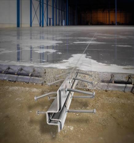
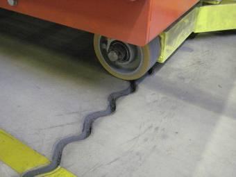
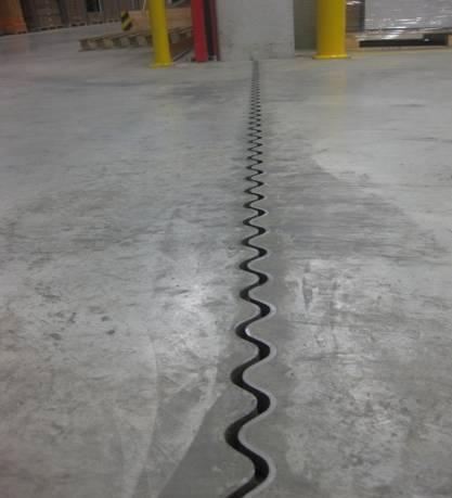
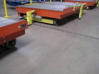
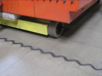
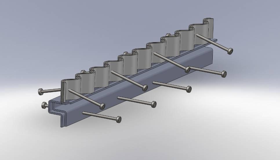
3 Description The construction and expansion joint is made of two continuous cold-rolled profiles in 5 mm thick SJ235JRG2 steel. These profiles fit together tightly due to their clever, standardised form. For anchoring into concrete, these profiles are provided with ø10 mm, 125 mm long anchor bolts that are automatically welded on every 200 mm using resistance butt welding. The top sides of the profiles are milled after being assembled to guarantee practically perfect flatness and straightness. The profiles are connected together using wing bolts with plastic nuts that do not need to be removed after being put in place. The profiles are assembled with an overlap of 15mm so that the next profile can easily be connected to the previous profile during installation. The profile is made in standard lengths of 3 m and is available in heights from 120 to 300 mm. We provide custom solutions above 300 mm. With their continuous form, these profiles prevent strain being concentrated during load transfer. This means that a higher and more smoothly load transfer is possible in comparison to discontinuous profiles. The patent pending joint with corrugated upper side in 5 mm thick steel ensures continuous support of passing wheels regardless of the direction, size and form of the wheel, from the placement of the joint to its maximum opening of 20 mm. By neutralising the striking impact of the wheels, forklift drivers experience unprecedented comfort. At the same time, maximum edge protection and load transfer are achieved, significantly reducing the chance of damage to the floor, the vehicle, or the goods being transported. This joint is especially recommended in thoroughfares and/or other areas of the floor that experience high forklift traffic. The Joints enables not only joint free floor slabs but the whole floor is experienced as Joint free. You can still see a joint but you don t feel it anymore. This is a new age in industrial flooring technology. This shock-and vibration free crossing will prevent any damage on your floor and save the investor huge amounts on wear and tear of forklifts. Only with the replacement costs of wheels the payback period of the investment is less than one year. Technical sheet joint page. 3 of 18
4 Characteristics Free horizontal expansion and contraction of the industrial floor. As the poured concrete dries, the inevitable contraction is taken up by the horizontal spreading of the expansion joint. This prevents the formation of cracks as a result of the drying process. This crack formation also occurs if a hole is cut into the floor too late, which is unnecessary with the installation of a dilatation joint. Preventing vertical movement The minute tolerances between the profiles and the typical Omega form connection prevent the slightest vertical movement between the separate floor sections that are created. The steel profiles also ensure the elastic behaviour of the joint. Load transfer With forklift traffic, the expansion joint provides a transfer of loads from one floor section to another. This means that the floor is less subject to wear, the chance of damage is reduced, and the lifetime of the industrial floor is lengthened considerably. The Sinus Slide version realize this load transfer is a noiseless and smoothly way. The wheels of the forklifts are sliding shock- and vibration free from one floor section to another. This creates an unprecedented level of comfort. Maximum load. The rigid steel structure ensures that maximum loads are handled with minimum deformation. Edge protection. The 5 mm thick steel profiles and especially the Sinus Slide joint give maximum edge protection. The joint will not only create an unprecedented level of comfort but will also avoid any crumbling of the edges of the floor sections. Construction joint profile The profiles are placed according to a layout plan with limited dimensions to separate the different floor sections. We advice floor slabs 30x30 meters in order to limit the opening gap of the joints to maximum 15 mm. The sections can then be poured and finished according to the daily schedule. Easy installation and compatible. The expansion joint is quite easy and quick to install according to the installation instructions given below in this technical documentation. The is 100% compatible with the Joint for every available height. Compliant with the European directive 2002/44/EC. The Sinus Slide joint guarantees shock- and even vibration free transfer between two floor sections even with forklifts with very small and hard wheels. With this feature the HC- Joint is compliant with the European directive 2002/44/EC concerning exposures of workers to whole body vibrations. Technical sheet joint page. 4 of 18
5 Product overview Type 1 Type 2 Type 3 HC-omega armour joint armour joint with 2 x 1 row anchor with 2 x 2 rows anchor Joint with 2 x 2 bolts bolts row anchor bolts Technical specifications of the armour joint Thickness 2 x 5 mm Steel grade SJ235JRG2 Length 3 m 3 m m Type of anchor bolts Ø10 lg 125 mm 2 x 5 pieces/m Automatically welded Ø10 lg 125 mm 2 x 10 pieces/m Automatically welded Ø10 lg 125 mm 2 x 10 pieces/m Automatically welded Production Cold rolled for optimal tolerances in construction Steel construction Profile height Finishing Fastening Concrete reinforcement Fittings Auxiliary equipment Straightness of horizontal surface Straightness of vertical surface Shock-free transfer mm Other dimensions by request Untreated natural steel electro-galvanized Stainless steel by request mm Other dimensions by request Top side milled mm Other dimensions by request 15 mm overlap at the end for smooth connections Attached with M6 x 20 wing bolts and polyamide plastic nuts. These attachments must not be removed after installation. The tensile force of the concrete breaks the connection with the polyamide nut. Both concrete with steel mesh and fibre reinforced concrete T- and X-shaped intersections Tool for height adjustment and placement 1 mm / 3 m 2 mm/3m N N YES Technical sheet joint page. 5 of 18
6 TYPE 1 Type and height a of joint type 1 = ax5 with 2x1 rows of anchors External (female) Omega profile a Internal (male) Omega profile b Floor thickness c Weight (Kg/m) Max Metres pro pallet Compatible with , , , , , , Technical sheet joint page. 6 of 18
7 TYPE 2 Type and height a of joint type 2 = ax5 with 2x2 rows of anchors Internal (male) Omega profile b external (female) Omega profile c Floor thickness d e Weight (Kg/m) Max Metres pro pallet Compatible with (+) 150* (+) 160* (+) 180* (+) 200* (+) 220 (+) 240 (+) 260 (+) 280 (+) , , , , , , , , , Technical sheet joint page. 7 of 18
8 TYPE 3 Technical sheet joint page. 8 of 18
9 type 3 = ax5 standard with 2x2 row of anchors Type and height a of joint Real height of the joint a Floor thicknes b c d Weight (Kg/m) Max Metres pro pallet *to make the joint compatible with the traditional straight joint the real height differs slightly. Compatible with 130* , * , (+) , (+) , (+) , (+) , (+) , (+) , (+) , (+) , (+) 300 Technical sheet joint page. 9 of 18


10 Accessories Crossings These are available in all dimensions in proportion to the profile used. X and T- crossings for traditional joints X, T and L-crossings for joints Assembly assistance Technical sheet joint page. 10 of 18


11 Load transfer The load transfer by the profile depends on a number of factors o A primary factor is a position variable. This indicates the position of the load relative to the joint and support. F v = P x (L-A) L o A second factor is the size of the load in proportion to the thickness of the floor. Load transfer is only provided from the moment that the load is large enough to move or deform the floor section until any play between the sections has been taken up. Small load Large load o A third factor that affects load transfer is the foundation. With a massive foundation, the loads will be supported by the foundation. In the case of a floor on piles, the load will have to be fully supported by the profile. Unstable foundation Massive foundation If a load is placed on the edge of a slab, the strain in the concrete is about 50% higher than a load in the middle of the slab. The expansion joint compensates this increase and will transfer up to 100% of this load to the adjoining slab, depending on the foundation, the position and size of the load. Technical sheet joint page. 11 of 18

12 Testing The joints have been tested to their maximum capacity by the Magnel lab associated with the University of Ghent. Test setup It was decided to test the joint without support such that the load transfer through the joint was maximized. The joint was placed in a test specimen with dimensions 1 m x 1.05 m. The joint openings of 10 mm and 20 mm were tested. For the concrete, a test was done with non-reinforced concrete (c30/37) and with fibre reinforced concrete (45 kg fibres/m 3 ). Test results Type Anchors upper/lower Openi ng Concrete height Fibre reinforced concrete (y/n) 140 Upper N Upper N Upper Y Upper Y Upper + lower Y Upper + lower Y 244 Failure load kn Technical sheet joint page. 12 of 18

13 Sample Calculation Analysis of the different ways the joint failed Technical data Concrete thickness H: 160 mm Height of the profile: h= 140 mm. Anchor failure strength: σ ank 450 N/mm 2 Failure strength of steel σ st = 350 N/mm 2 Characteristic compression strength of the concrete f ck = 25 N/mm 2 Anchor diameter ø10 mm Load transfer 50% P = force per length unit n ank = Number of anchors per length unit ζ= shear stress Different ways of failure Hc-Omega with one row of anchors 1. Failure of the concrete due to shear: P = 1/Load transfer * H * 2 * ζ where ζ = 0.05 x* f ck / 1.5 P = 1/0.5 * 160 * 2 * 0.05 x 25 / 1.5 = 377 kn 2. Failure of the anchors on the side of the nose P = 1/load transfer * (a * 2 * ζ + A ank * n ank * ζ ank) where ζ ank = 0.8 x* σ ank Technical sheet joint page. 13 of 18
14 P = 1/0.5 * (70 * 2 * 0.05 * 25 / * Л/4 * 6 * 0.8* 0.45) P = 504 kn 3. Failure of the profile P = 1/load transfer * A * ζ st where ζ st = 0.8 x* σ st P = 1/0.5 * (5 * 4 * 0.8* 350) P = 11,200 kn 4. Failure of the anchors on the flat side P = 1/load transfer * (a * ζ + A ank * n ank * ζ ank) where ζ ank = 0.8 x* σ ank P = 1/0.5 * (20 * 0.05 * 25 / * Л/4 * 6 * 0.8* 0.45) P = 372 kn For the given example, the load applied along the joint could reach 372 kn taking into account that 50% of this charge is transferred. Hc-Omega with two rows of anchors 1. Failure of the concrete due to shear: P = 1/Load transfer * H * 2 * ζ where ζ = 0.05 x* f ck / 1.5 P = 1/0.5 * 160 * 2 * 0.05 x 25 / 1.5 = 377 kn 2. Failure of the anchors on the side of the nose P = 1/load transfer * (a * 2 * ζ + A ank * n ank * ζ ank) where ζ ank = 0.8 x* σ ank P = 1/0.5 * (70 * 2 * 0.05 * 25 / * Л/4 * 10 * 0.8* 0.45) P = 730 kn Technical sheet joint page. 14 of 18
15 3. Failure of the profile P = 1/load transfer * A * ζ st where ζ st = 0.8 x* σ st P = 1/0.5 * (5 * 4 * 0.8* 350) P = 11,200 kn 4. Failure of the anchors on the flat side P = 1/load transfer * (a * ζ + A ank * n ank * ζ ank) where ζ ank = 0.8 x* σ ank P = 1/0.5 * (20 * 0.05 * 25 / * Л/4 * 10 * 0.8* 0.45) P = 598 kn For the given example, the load applied along the joint could reach 598 kn taking into account that 50% of this charge is transferred. However the failure of the concrete will be at 377 kn The values given in this example are only indicative values and must always be verified by a structural engineer. The safety factors must be chosen in function of the application and rulings. Higher safety factors must be used for dynamic loads than for static loads. For floors on piles, we always recommend expansion joints with two rows of anchors. Technical sheet joint page. 15 of 18
16 Installation instruction The floor slab should be divided into square sections as much as possible. If this is not possible, the proportion of 3/2 for the width/length of the floor slab should be respected as much as possible. The distance between the joints is determined in function of the expected shrinkage of the concrete. The shrinkage of a floor slab is strongly dependent on a number of thermal variables as well as the quality of the concrete. Shrinkage can vary between 0,3 to 0,5 mm/meter. In any case, an attempt must be made to limit the opening of the joints to a maximum of 20 mm. An indication in normal conditions would be floor sections of 30 to 40 metres. However, the advice of the project leader or expert is always recommended because shrinkage can vary considerably from country to country due to local environmental factors and concrete quality. For intensively loaded floor sections, such as floors at loading bays and thoroughfares, we advise the use of the patent pending joint. The added cost is minimal relative to the total project investment, and is quickly recovered in view of the many advantages. Only with savings on the replacement costs of forklift s wheels the payback period is less than one year. Fixed structures in the building such as columns and walls must be isolated with compressible material. Ensure that no fixed connections are placed between 2 different floor slabs that could hinder the movement of these floor slabs, e.g. racks, conveyor belts, crash barriers, etc. For some floors that are placed on a watertight membrane or insulation for example, the use of anchoring in the ground is not permitted. As an alternative we have adjustable placement feet available or other custom made solutions in our product range that do not require drilling through the foundation. For floors on supporting piles, we always advise dilatation joints with a double row of anchors. Check the presence of utilities and underground lines when using anchoring with pins in the ground. Technical sheet joint page. 16 of 18
17 A demonstration video of these installation instructions is available on our website at This can be found on the page PROFILES / HC-O joint. 1. String a line in the location where the profiles are to be installed. 2. Lay the joints out along this line. 3. Place the first joint parallel to this line. 4. Bring them to the correct height using wedges or the height adjustment tool. (See accessories) 5. Hammer or drill pins into the ground vertically along the ends of the anchors with 2 on each side of the end of the profile. If desired, an additional pin can be placed in the middle of the profile. 6. Check the height level of the profile with a laser and check the alignment relative to the taut line. 7. Use a spirit level to check the levelness of the profile across the length. 8. Weld the pins to the profile. If welding work is not permitted on site, special adjustment feet are available. 9. Place the next profile with its overlap in the first profile. With the overlapping, the start of this profile is immediately at the correct height. 10. Bring the end of the second profile to the correct height with wedges or the height adjustment tool. 11. Repeat these steps from point 5 until an intersection, wall or column is reached. For intersections: 1. Place the intersection in the location specified on the layout plan. 2. Measure the distance between the last placed joint and the intersection. Cut the joint to be placed to the correct length using a cutting disc. 3. Place the joint that has been cut to length according to the procedure described above. 4. Bring the intersection to the correct level and weld it to the joint. Remember to weld the supplied noses on to prevent the penetration of poured concrete into the joint. Technical sheet joint page. 17 of 18
18 Maintenance and finishing The dilatation joint is designed to protect the edges of concrete slabs that are automatically formed when the joint opens due to the shrinkage that occurs in the drying process. We advise filling the openings that are created with a joint or sealing product to prevent the accumulation of dirt and dust in the joint. Sealing the joint is possible for traditional joints as for Joint. The final sealing may only be done once the expansion of the joint is stabilised. Technical sheet joint page. 18 of 18
Technical Data Sheet: The Corrugated HC-Omega
 Performance Structural Concrete Solutions, LLC P.O. Box 2377, Davidson, NC 28036-2377 P: 980-333-6414 info@pscs-llc.com www.pscs-llc.com Technical Data Sheet: The Omega Figure 1. Omega armor joint on grade.
HC Sinus Slide joints for lasting repairs in industrial floors
 HC Sinus Slide joints for lasting repairs in industrial floors Damaged joints in floors are a real nightmare for every warehouse and facility manager. It is a source of continuous frustration and annoyance
SigmaJoint. The Ultimate Joint J. Armouring & Load Transfer Systems. Metallic Leave-In-Place Contraction & Day Joints for INDUSTRIAL CONCRETE FLOORS
 SigmaJoint Metallic Leave-In-Place Contraction & Day Joints for INDUSTRIAL CONCRETE FLOORS TYPE - D TYPE - O The Ultimate Joint J Armouring & Load Transfer Systems SigmaJoint Introduction Joints are unavoidable
Load transfer at joints for industrial floors. Where do we come from?
 Load transfer at joints for industrial floors Where do we come from? Traditional load transfer calculations have been based on bending and shear of steel bars or plates connecting adjacent concrete panels
TILT-UP PRECAST CONCRETE SANDWICH PANELS. A. Work includes, but is not limited to, the following:
 PART 1 GENERAL 1.01 SUMMARY SECTION 03460 TILT-UP PRECAST CONCRETE SANDWICH PANELS A. Work includes, but is not limited to, the following: 1. Architectural precast concrete sandwich wall panels. 2. Integral
Important: Before You Start
 Advantage ICF System Advantage ICF System TM Field Guide Important: Before You Start Does Your Building Inspector Know You Are Building with the Advantage ICF System? You are required to check with your
SECTION TILT-UP PRECAST CONCRETE SANDWICH PANELS. A. Work includes, but is not limited to, the following:
 PART 1 GENERAL 1.01 SUMMARY SECTION 03460 TILT-UP PRECAST CONCRETE SANDWICH PANELS A. Work includes, but is not limited to, the following: 1. Architectural precast concrete sandwich wall panels. 2. Integral
Performance Floors for Warehouses and Distribution Centres. Kevin Dare, Managing Director, Face Consultants Ltd.
 Performance Floors for Warehouses and Distribution Centres Kevin Dare, Managing Director, Face Consultants Ltd. Performance Floors for Warehouses and Distribution Centres. Kevin Dare, Face Consultants
DESIGN AND CONSTRUCTION OF HEAVY INDUSTRIAL ANCHORAGE FOR POWER-PLANTS
 DESIGN AND CONSTRUCTION OF HEAVY INDUSTRIAL ANCHORAGE FOR POWER-PLANTS Peter J. Carrato, William F. Brittle Bechtel Power Corporation, USA Abstract Fossil fueled power-plant projects provide many design
DuraComp Composite Decking Installation Guide. Hidden Plastic Clip Fixing
 Composite Decking Installation Guide Hidden Plastic Clip Fixing Table of Contents SECTION ONE: General Information Site Preparation......2 Site Storage.....2 Safety. 2 Tools....2 Foundation & Sub Structure.2
ULTRAPLUS M12-M36. The undercut anchor for exceptionally high loads in cracked and non-cracked concrete also for shock and seismic loads.
 ULTRAPLUS M12-M36 LIEBIG The ORIGINAL Anchoring Technology The undercut anchor for exceptionally high loads in cracked and non-cracked concrete also for shock and seismic loads. FUNCTION When the anchor
MIGUTAN. Installation instructions. MIGUTAN-Systems with short AAS sheets
 Installation instructions MIGUTAN-Systems with short AAS sheets 1.1 General Information MIGUTAN systems will be fabricated according to a site measurement to ensure perfect fit. The metal parts will be
ULTRAPLUS M12-M36. The undercut anchor for exceptionally high loads in cracked and non-cracked concrete also for shock and seismic loads.
 ULTRAPLUS M12-M36 The undercut anchor for exceptionally high loads in cracked and non-cracked concrete also for shock and seismic loads. FUNCTION When the anchor is installed the expansion segments are
DRIVE-IN PALLET RACKING
 DRIVE-IN PALLET RACKING Storage by accumulation : optimal use of available space www.stamh.com DRIVE-IN PALLET RACKING Designed for the storage of homogenous products Accommodates a large number of pallets
1. Cast-in-place concrete is specified in Section
 SECTION 03 38 00 PART 1 - GENERAL 1.01 DESCRIPTION A. This Section describes the requirements for furnishing and installing post-tensioned slabs, jacks, jacking and anchors at Parking Structure, and record
complete with pallet support bars, column guards, safety barriers, pallet back stopper painting
 DESCRIPTION / SPECIFICATIONS OF GOODS The Goods to be supplied by the Supplier include the following: The scope of works including:- 1. Supply, delivery and installation of pallet racking system as follow:-
SECTION COMPOSITE METAL DECKING
 PART 1 GENERAL 1.1 DESCRIPTION SECTION 05 36 00 1. Use this section only for NCA projects. 2. Delete between // ---- // if not applicable to project. Also delete any other item or paragraph not applicable
Installation Guide. PAROC panel solutions
 Installation Guide PAROC panel solutions Panel System 4.00 INT January 2008 THESE INSTRUCTIONS ARE FOR NORMAL APPLICATIONS Work safety Preparation Wear protective gloves and clothing when handling the
Heartland Perma-Column 1841 E 1450 Rd. Lawrence, KS (785)
") Perma-Column Installation Instructions Unlike any other concrete post-frame foundation system, Perma-Column Precast Concrete Piers use 10,000 psi concrete and our unique Sturdi-Wall Plus wet-set bracket
Perma-Column Installation Instructions Unlike any other concrete post-frame foundation system, Perma-Column Precast Concrete Piers use 10,000 psi concrete and our unique Sturdi-Wall Plus wet-set bracket
Instructions for the use of the Link 4 Pallet Rack Lifter (PRL) model 5000
 model 5000") Instructions for the use of the Link 4 Pallet Rack Lifter (PRL) model 5000 (How to move your pallet racking using the Link 4 Pallet Rack Lifter) This process is for a typical rack move and reset. Each
Instructions for the use of the Link 4 Pallet Rack Lifter (PRL) model 5000 (How to move your pallet racking using the Link 4 Pallet Rack Lifter) This process is for a typical rack move and reset. Each
PC Beam Shoe. Corbel system to support beams. Technical Manual. Version: DK 4/2012 Design standard: DS EN Eurocodes + NA (Denmark)
") PC Beam Shoe Corbel system to support beams Version: DK 4/2012 Design standard: DS EN Eurocodes + NA (Denmark) Technical Manual PC Beam Shoe Corbel system to support beams System benefits Easy and fast
PC Beam Shoe Corbel system to support beams Version: DK 4/2012 Design standard: DS EN Eurocodes + NA (Denmark) Technical Manual PC Beam Shoe Corbel system to support beams System benefits Easy and fast
PRODUCT DATA SHEET SikaProof A
 FULLY BONDED FPO SHEET MEMBRANE WATERPROOFING SYSTEM FOR BASEMENTS AND OTHER BELOW GROUND STRUCTURES DESCRIPTION is a fully and permanently bonded, selfadhesive, composite sheet membrane waterproofing
Installation Manual. Foundations. Version 4.3ᵠ
 Installation Manual Foundations Version 4.3ᵠ (*) - Denotes Current Revisions throughout this Installation Manual Version 4 (ᵠ) - Denotes Current Revisions for Version 4.3 of this Manual Manual updated
A. Product Data: For each type of cold-formed steel framing product and accessory.
 SECTION 05400 - COLD-FORMED METAL FRAMING PART 1 - GENERAL 1.1 SUMMARY A. Section Includes: 1. Exterior non-load-bearing wall framing. 1.2 ACTION SUBMITTALS A. Product Data: For each type of cold-formed
SECTION ORNAMENTAL WELDED STEEL FENCING
 SECTION 032300 ORNAMENTAL WELDED STEEL FENCING PART 1 - GENERAL 1.1 RELATED DOCUMENTS A. Drawings and general provisions of the Contract, including General and Supplementary Conditions and Division 01
CI/SfB (52.5) January 2004 Uniclass L L2123. ACO LightShaft Daylight and fresh air. Naturally.
 January 2004 Uniclass L L2123. ACO LightShaft Daylight and fresh air. Naturally.") CI/SfB (52.5) January 2004 Uniclass L7315 + L2123 ACO LightShaft Daylight and fresh air. Naturally. OVERVIEW Why choose ACO LightShaft? Maximum daylight transmission thanks to bright white polypropylene
CI/SfB (52.5) January 2004 Uniclass L7315 + L2123 ACO LightShaft Daylight and fresh air. Naturally. OVERVIEW Why choose ACO LightShaft? Maximum daylight transmission thanks to bright white polypropylene
lindab we simplify construction LindabSandwichPanels Installation instructions Mineral Wool Panels
 lindab we simplify construction LindabSandwichPanels Installation instructions Mineral Wool Panels Assembly instructions Handling Receiving of goods Check that the material has not been damaged in transit
INSTALLATION. Step 6. Step 7. Step 8
 INTLLTION The following installation instructions and the relative drawings are given only as an example not considering any peculiarities of the installation site or soil characteristics, or morphology
Construction. Fully bonded FPO sheet membrane waterproofing system for basement and other below ground structures. Product Description.
 Product Data Sheet Version 2014-05-27 Identification no: 020704103000000001 SikaProof A SikaProof A Fully bonded FPO sheet membrane waterproofing system for basement and other below ground structures Construction
Racking systems RACKING SYSTEMS. IT S EASY TO ORDER sales hotline:
 Racking systems Bar and Sheet Racking and Storage...40 Supershelf Tyre Racking...44 Pallet Racking...45 Protection for Racking and Columns...46 IT S EASY TO ORDER www.action-storage.co.uk sales hotline:
Installation Manual. Foundations. Version 2
 Installation Manual Foundations Version 2 Contents Overview...1 Planning the Job... 2 Introducing DMX FlexSheet...2 Supplies Required...3 Tools Required...4 Preparing the Site...4 Where to Start?...5 Installing
Section REINFORCING STEEL
 Section 03210 PART 1 GENERAL 1.01 SUMMARY This Section includes the furnishing and subsequent placing of reinforcing steel, deformed and smooth, chairs, ties, splicing devices, and other reinforcing accessory
SPECIFICATION FOR REINFORCED SOIL WALL
 SPECIFICATION FOR REINFORCED SOIL WALL 1.0 EXTENT OF WORK The work shall consist of Reinforced Soil walls built in accordance with this specification and in conformity with the lines, levels and details
EASY CONVEYORS OVERVIEW
 EASY CONVEYORS OVERVIEW TABLE TOP CONVEYOR SYSTEMS MAT TOP CONVEYOR SYSTEMS CONVEYOR COMPONENTS BELT CONVEYORS SYSTEMS ROLLER CONVEYOR SYSTEMS www.autoline.net.nz www.easy-conveyors.com Easy Conveyors
Design Guidance for TAB-Deck Composite Slabs using SMD Metal Decking reinforced with ArcelorMittal Steel Fibres
 Design Guidance for TAB-Deck Composite Slabs using SMD Metal Decking reinforced with ArcelorMittal Steel Fibres Version 2 Revised October 2008 Design Guidance for TAB-Deck Composite Slabs using SMD Metal
540 20th Avenue, Lachine, Qc, H8S 3T1 T TF MEZZANINE
 540 20th Avenue, Lachine, Qc, H8S 3T1 T 514.634.7292 TF 800.361.2242 Info@federalsteel.ca www.federalsteel.ca MEZZANINE 03 What s your challenge? Table of Content 04 05 06 Design load Bracing Floor options
CAR PARKS DURABLE SOLUTIONS FOR CAR PARKS
 CAR PARKS DURABLE SOLUTIONS FOR CAR PARKS PROVIDING WATERTIGHT TRANSITIONS WITH C/S ALLWAY EXPANSION JOINT COVERS Standard duty expansion joint covers aren t durable enough to withstand the constant heavy
Openings in Walls I: Reinforcement
 Openings in Walls I: Reinforcement INTRODUCTION These general construction techniques are chosen to introduce low-tech and low-cost construction. Combined with good quality control, they can create buildings
Steel fibres Structural applications
 WireSolutions Steel fibres Structural applications TAB-Slab TAB-Structural TAB-Deck TAB-Raft ArcelorMittal & WireSolutions Transforming tomorrow ArcelorMittal ArcelorMittal is the world leader in the steel
Facilitating innovative bridge design the bearings and expansion joints of the Golden Ears Bridge
 IABSE-JSCE Joint Conference on Advances in Bridge Engineering-II, August 8-10, 2010, Dhaka, Bangladesh. ISBN: 978-984-33-1893-0 Amin, Okui, Bhuiyan (eds.) www.iabse-bd.org Facilitating innovative bridge
PFEIFER Lifting Anchors: The original as standard for quality and a maximum of safety.
 PFEIFER Lifting Anchors: The original as standard for quality and a maximum of safety. 16 PFEIFER Round Thread Exceptionally robust thread even no chance for hammer blows Not sensitive against dirt enables
R-Group Finland Oy. REA Lifting Inserts Technical Manual According to Eurocodes, EU Machinery directive 2006/42/EC and VDI/BV-BS 6205 CE Approved
 R-Group Finland Oy REA Lifting Inserts Technical Manual According to Eurocodes, EU Machinery directive 2006/42/EC and VDI/BV-BS 6205 CE Approved 10.2.2017 2 Table of Contents 1 DESCRIPTION OF THE SYSTEM...
2 PALLET P RA ALLET CKING RA
 PALLET RACKING 2 PALLET RACKING 3 The pallet racking system uses simple modular construction for storing pallets that provides great variability for both small and large storage spaces. Pallet racks are
Multideck 146. Contents
 Contents Specification and Design 55 Load Tables 57 Fire Performance 60 Sound Attenuation 63 Concrete Volume Savings composite steel deck is optimised to minimise the concrete volumes on longer spans providing
SECTION COLD-FORMED METAL FRAMING
 SECTION 05 40 00 COLD-FORMED METAL FRAMING SPEC WRITER NOTE: Delete between //---// if not applicable to project. Also delete any other item or paragraph not applicable in the section and renumber the
SECTION 415 REINFORCING FOR CONCRETE
 SECTION 415 REINFORCING FOR CONCRETE Module 5 August 2018 Release 10, Module 5 1 Release 10, August 2018 5-1 415 1 Description Furnish and place steel and fiber reinforced polymer (FRP) reinforcing of
TECHNICAL MANUAL. PC Beam Shoe. Hidden Beam Shoe for Corbel System
 TECHNICAL MANUAL PC Beam Shoe Hidden Beam Shoe for Corbel System Version: PEIKKO GROUP 03/2012 PC Beam Shoe Corbel system to support beams System benefits Easy and fast beam installationtion Fits into
SECTION DETECTABLE GUIDE TACTILES
 SECTION 09655 PART 1 - GENERAL 1.01 DESCRIPTION A. Section includes specifications for surface applied and recessed detectable guide or directional tactiles (tactiles) for use on the station platforms
SECTION ORNAMENTAL ALUMINUM FENCING
 SECTION 032300 ORNAMENTAL ALUMINUM FENCING PART 1 - GENERAL 1.1 RELATED DOCUMENTS A. Drawings and general provisions of the Contract, including General and Supplementary Conditions and Division 01 Specification
TRITEC light Steel Panel Formwork
 TRITEC light Steel Panel Formwork Perfection made in Germany Various practical illustrations of TRITEC Panel Combinations Guaranteed the largest possible range of sizes with the least possible amount of
Galvanized Steel Bead Accessories for Stucco and Plaster Installations ALABAMA METAL INDUSTRIES CORPORATION. Contract Number:
 SUBMITTAL SUBMITTAL TRANSMITTAL DETAILS AMICO Galvanized Steel Bead Accessories for Stucco and Plaster Installations Project Submittals as manufactured by Submittal Date: Contract : Project Name: Section
DEXION RACKING. The Product picture Effect of picture. 80/90/100/120/mm POST. Standard Medium Heavy Extra Heavy
 DEXION RACKING Upright Profiles 75mm upright pitch Cold Forming Process on a high speed rolling mill Omega section, Front-Centre-Ribbed Powder coated finish Profile width 80x70, 90x70, 100x70, 120x70mm
Structural Tests and Special Inspections Form. Inspection of Fabricators (1704.2)
") Inspection of Fabricators (1704.2) Furnish inspection reports (1704.2.1) - Fabricators that have not been approved Provide a Certificate of Compliance (1704.2.2) - Approved Fabricators Steel Construction
Inspection of Fabricators (1704.2) Furnish inspection reports (1704.2.1) - Fabricators that have not been approved Provide a Certificate of Compliance (1704.2.2) - Approved Fabricators Steel Construction
84 Lapping & Jointing 86 Service Pipe Penetrations 87 Sealing to Cavity Wall Constructions 88 Protecting Membranes System Components.
 84 Lapping & Jointing 86 Service Pipe Penetrations 87 Sealing to Cavity Wall Constructions 88 Protecting Membranes 90 System Components installation/ SYSTEM COMPONENTS INSTALLATION ADVICE LAPPING and JOINTING
SECTION COLD-FORMED METAL TRUSSES
 SECTION 054400 COLD-FORMED METAL TRUSSES PART 1 - GENERAL 1.1 RELATED DOCUMENTS A. Drawings and general provisions of the Contract, including General and Supplementary Conditions and Division 01 Specification
INSTALLATION MANUAL FOR MODULAR EXPANSION JOINT (LG SYSTEM)
") INSTALLATION MANUAL FOR MODULAR EXPANSION JOINT (LG SYSTEM) TABLE OF CONTENTS 1. INTRODUCTION TO THE MODULAR EXPANSION JOINT 1.1 Purpose 1.2 How They Work 1.3 Movement Capacity 1.3.1 Longitudinal Direction
INSTALLATION MANUAL FOR MODULAR EXPANSION JOINT (LG SYSTEM) TABLE OF CONTENTS 1. INTRODUCTION TO THE MODULAR EXPANSION JOINT 1.1 Purpose 1.2 How They Work 1.3 Movement Capacity 1.3.1 Longitudinal Direction
SKATEWHEEL FLOW RACK
 SKATEWHEEL FLOW RACK 2 ASSEMBLY INSTRUCTIONS: Steel King Industries recommends that this product be assembled only by qualified personnel, experienced in assembly of storage racks, and knowledgeable of
Drain DESIGN & INSTALLATION GUIDE 316L STAINLESS STEEL INDUSTRIAL FLOOR DRAINS & LINEAR DRAINAGE CHANNELS
 DESIGN & INSTALLATION GUIDE 316L STAINLESS STEEL INDUSTRIAL FLOOR DRAINS & LINEAR DRAINAGE CHANNELS KEMDRAIN TM STAINLESS INDUSTRIAL FLOOR DRAINS AND LINEAR CHANNELS, OFFERING ALL THE BENEFITS OF 316L
SPECIFICATION FOR TUBULAR STEEL LIGHTING COLUMN. Reference is made in this Specification to the following:
 SPECIFICATION FOR TUBULAR STEEL LIGHTING COLUMN 1. SCOPE This specification covers the design, fabrication and testing of tubular section, galvanised steel friction fit jointed street light columns of
SPECIAL INSPECTION AGREEMENT
 PART 1 STATEMENT OF SPECIAL INSPECTIONS When special inspection is required to be performed in accordance with International Building Code Chapter 17, a building permit cannot be issued until a statement
R-Group Finland Oy. RLA Lifting Inserts Technical Manual According to Eurocodes, EU Machinery directive 2006/42/EC and VDI/BV-BS 6205 CE Approved
 R-Group Finland Oy RLA Lifting Inserts Technical Manual According to Eurocodes, EU Machinery directive 2006/42/EC and VDI/BV-BS 6205 CE Approved 16.8.2017 2 Table of Contents 1 DESCRIPTION OF THE SYSTEM...
Assembly and users manual. Pallet racking Alfa
 Assembly and users manual Pallet racking Alfa ASSEMBLING OF FRAMES Tightening Torque Screw M0 8.8 Max. tightening torque 7 Nm Taptite M6 Max. tightening torque 5 Nm Taptite M8 Max. tightening torque 5
The Passive Fire Protection Handbook
 The Passive Fire Protection Handbook The UK s comprehensive guide to passive fire protection Chapter Ceilings, Floors and Roofs AUGUST 0 The Passive Fire Protection Handbook Contents Chapter : Introduction
the high capacity conveyor for improved unit flow
 the high capacity conveyor for improved unit flow The heavy duty conveyor, designed for high capacity transport both vertically and horizontally Jonge Poerink Conveyors Modulary design fits easily into
SK2000 Boltless Pallet Rack Installation and Assembly Manual
 SK2000 Boltless Pallet Rack Installation and Assembly Manual Steel King Industries, Inc. 2700 Chamber St Stevens Pont, WI 54481 (800) 826 0203 www.steelking.com info@steelking.com ASSEMBLY INSTRUCTIONS:
ADVANTAGES THE LIGHTEST FILLING SOLUTION HIGH LOAD-BEARING CAPACITY
 SINGLE-USE FORMWORK SYSTEM UP TO 300 CM elevetor new the evolution of crawl space LOGISTICAL ADVANTAGES THE LIGHTEST FILLING SOLUTION HIGH LOAD-BEARING CAPACITY w w w. g e o p l a s t. i t BUILDING 02
CONNECTOR B L O C K S H E A R. Design for Composite Structural Action BLOCK SHEAR CONNECTOR APPLICATION. Airspace
 B L O C K S H E A R CONNECTOR BLOCK SHEAR CONNECTOR APPLICATION Airspace Design for Composite Structural Action Exterior ashlar-type masonry veneer, typically of clay brick or concrete block masonry, are
SECTION REINFORCING STEEL
 SECTION REINFORCING STEEL 1. DESCRIPTION This specification shall govern the furnishing and placing of reinforcing steel, deformed and smooth, of the size and quantity designated on the plans and in accordance
CANTILEVER RACK SPECIFICATIONS PART 1 GENERAL 1.1 SCOPE 1.2 APPROVED MANUFACTURER 1.3 REGULATORY ORGANIZATIONS AND GROUPS 1.4 QUALITY ASSURANCE
 CANTILEVER RACK SPECIFICATIONS PART 1 GENERAL 1.1 SCOPE This specification is intended to describe the general requirements applicable to a proper structural cantilever rack design. In addition, it is
Hilti HIT-HY 200-R 500 ml foil pack (also available as 330 ml foil pack) Static mixer
 Static mixer") with HIT-V Hilti HIT-HY 200 with HIT-V Injection Mortar System Benefits Hilti HIT-HY 200-R 500 ml foil pack (also available as 330 ml foil pack) Static mixer HIT-V rods HIT-V (Zinc) HIT-V-F (Gal) HIT-V-R
with HIT-V Hilti HIT-HY 200 with HIT-V Injection Mortar System Benefits Hilti HIT-HY 200-R 500 ml foil pack (also available as 330 ml foil pack) Static mixer HIT-V rods HIT-V (Zinc) HIT-V-F (Gal) HIT-V-R
CONNECTOR S T U D S H E A R. Design for Composite Structural Action STUD SHEAR CONNECTOR APPLICATION
 S T U D S H E A R CONNECTOR STUD SHEAR CONNECTOR APPLICATION Design for Composite Structural Action Exterior ashlar-type masonry veneer, typically of clay brick or concrete block masonry, are commonly
SECTION METAL STAIRS
 SECTION 05510 METAL STAIRS PART 1 GENERAL 1.01 SECTION INCLUDES A. Stairs with concrete treads. B. Stairs with metal treads. C. Structural steel stair framing and supports. D. Handrails and guards. 1.02
80/90/100/120/mm POST Standard Medium Heavy Extra Heavy
 Upright Profiles 75mm upright pitch Cold Forming Process on a high speed rolling mill Omega section, Front-Centre-Ribbed Powder coated finish Profile width: 80x70, 90x70, 100x70, 120x70mm Standard JIS
" RISKS ASSOCIATED WITH THE INSTALLATION OF THE SYSTEM
 PALLET RACK 85-110 installation, use and maintenance instructions Shelving made entirely of first grade certified steel sheet and cold-profiled steel with galvanized steel according to SENDZIMIR process
Polycrete Big Block Standard Specification
 Polycrete Big Block Standard Specification SECTION 03 11 19 INSULATED CONCRETE FORMING 10/13 PART 1 GENERAL 1.1 REFERENCES The publications listed below form a part of this specification to the extent
Preventing Water Leakage through Construction Joints using SYNKOFLEX Preformed Compressible Waterstop
 Preventing Water Leakage through Construction Joints using SYNKOFLEX Preformed Compressible Waterstop Introduction A typical problem in most Water Retaining Structures is the leakage of water through Construction
UNIVERSITY OF BOLTON WESTERN INTERNATIONAL CENTRE FZE. BEng (HONS) CIVIL ENGINEERING SEMESTER ONE EXAMINATION 2015/2016
 CIVIL ENGINEERING SEMESTER ONE EXAMINATION 2015/2016") OCD59 UNIVERSITY OF BOLTON WESTERN INTERNATIONAL CENTRE FZE BEng (HONS) CIVIL ENGINEERING SEMESTER ONE EXAMINATION 2015/2016 ADVANCED STRUCTURAL ANALYSIS AND DESIGN MODULE NO: CIE6001 Date: Tuesday 12
OCD59 UNIVERSITY OF BOLTON WESTERN INTERNATIONAL CENTRE FZE BEng (HONS) CIVIL ENGINEERING SEMESTER ONE EXAMINATION 2015/2016 ADVANCED STRUCTURAL ANALYSIS AND DESIGN MODULE NO: CIE6001 Date: Tuesday 12
SECTION (16071) - VIBRATION AND SEISMIC CONTROLS FOR ELECTRICAL SYSTEMS
 - VIBRATION AND SEISMIC CONTROLS FOR ELECTRICAL SYSTEMS") SECTION 26 05 48 (16071) - VIBRATION AND SEISMIC CONTROLS FOR ELECTRICAL SYSTEMS PART 1 GENERAL 1.01 SUMMARY A. This Section includes seismic restraints and other earthquake-damage-reduction measures for
SECTION 26 05 48 (16071) - VIBRATION AND SEISMIC CONTROLS FOR ELECTRICAL SYSTEMS PART 1 GENERAL 1.01 SUMMARY A. This Section includes seismic restraints and other earthquake-damage-reduction measures for
The Freudenberg Politex Group
 Waterproofing easy to lay dimensionally stable waterproof resistant PATENT PENDING New-generation of waterproofing METHOD FOR LAYING is laid dry on both wooden and cement supports. Laying is easy and fast:
SECTION STRUCTURAL STEEL
 SECTION 05120 PART 1 - GENERAL 1.1 RELATED DOCUMENTS A. Drawings and general provisions of the Contract, including General and Supplementary Conditions and Division 1 Specification Sections, apply to this
CHAPTER III DYNAMIC BEHAVIOR OF A LABORATORY SPECIMEN
 CHAPTER III DYNAMIC BEHAVIOR OF A LABORATORY SPECIMEN To address the vibration response of a long span deck floor system, an experiment using a specimen that resembles the conditions found in the in-situ
ST7008 PRESTRESSED CONCRETE
 ST7008 PRESTRESSED CONCRETE QUESTION BANK UNIT-I PRINCIPLES OF PRESTRESSING PART-A 1. Define modular ratio. 2. What is meant by creep coefficient? 3. Is the deflection control essential? Discuss. 4. Give
SMART CUSHION INNOVATIONS SCI100GM General Specifications
 SMART CUSHION INNOVATIONS SCI100GM General Specifications DESCRIPTION: The SCI100GM is a redirective, non-gating crash attenuator that consists of a base, supporting frames, a sled, side panels, a wire
Universal Armorwire Terminal End
 Installation Manual Universal Armorwire Terminal End Anchoring for 3 & 4 Cable Barriers VHD (v2) 300914 Table of Contents Universal A.T.E Introduction.. 3 Limitations and Warnings.... 3 Before Installation..
APEX ADJUSTABLE PALLET RACKING
 ~ STORAGE DESIGN LTD ~ 018 STORAGE DESIGN LTD TEL:0144677614 info@storage-design.ltd.uk www.storage-design.ltd.uk These instructions are designed to give an easy, step by step guide to assembling APEX
ArmorWire Cable Barrier
 Installation Manual ArmorWire Cable Barrier TL-3 & TL-4 Systems VHD (v2) 300914 Table of Contents ArmorWire Introduction......... 3 Limitations and Warnings... 3 Before Installation. 3 Design Considerations......
Planning and installation instructions
 Planning and installation instructions Stofix Oy Ahlmaninkatu 2 E 40100 Jyväskylä Finland stofixgroup@stofix.com www.stofix.com 2 PLANNING AND INSTALLATION INSTRUCTIONS... 1 1 General... 3 2 Project Design...
Masonry and Cold-Formed Steel Requirements
 PC UFC Briefing September 21-22, 2004 Masonry and Cold-Formed Steel Requirements David Stevens, ARA Masonry Requirements Composite Construction Masonry is often used in composite construction, such as
Exterior Wall Solutions Building Shell
 A strong, water tight and thermally insulated building shell will ensure the buildings sustainability of usage over time. The Exterior Shell is the most important factor of protection to ensure that the
RUUKKI FAÇADE SYSTEMS
 www.ruukki.co.uk RUUKKI FAÇADE SYSTEMS 1. General Ruukki Forma is a complete façade system in which Ruukki energy panels form an energy efficient base structure and Ruukki cladding products finalize the
Reinforced Earth wall Construction Manual
 COVER PAGE CT-PE-W02 Rev: 5 Reinforced Earth wall Construction Manual Concrete Facing Reinforced Earth Malaysia Sdn Bhd 80-1, Jalan 8/62A Bandar Menjalara 52200 Kuala Lumpur Tel : 03-62746162, Fax : 03-62747212
TECHNICAL MANUAL. TENLOC Panel Connector. Hidden Latch Connection for Precast Panels
 TECHNICAL MANUAL TENLOC Panel Connector Hidden Latch Connection for Precast Panels Version: Peikko Group 06/2018 TENLOC Panel Connector Fast connection for precast elements TENLOC Panel Connector is a
Structural Calculations for standard BALCONY 1 system handrail using 55mm diameter posts (48.3mm x 5mm CHS) & 150 x 150 x 15mm base plates
 & 150 x 150 x 15mm base plates") Balcony 1 system handrail PAGE 1 (B1NB55150150BP061016) Structural Calculations for standard BALCONY 1 system handrail using 55mm diameter posts (48.3mm x 5mm CHS) & 150 x 150 x 15mm base plates Our ref:
Balcony 1 system handrail PAGE 1 (B1NB55150150BP061016) Structural Calculations for standard BALCONY 1 system handrail using 55mm diameter posts (48.3mm x 5mm CHS) & 150 x 150 x 15mm base plates Our ref:
ALADIN (formerly known as Jeene Joint)
") Structural Sealing Expansion Joint System DESCRIPTION ALADIN is a structural sealing joint system comprised of a neoprene profile, which is air-pressurized and bonded in place with a specially formulated
Structural Sealing Expansion Joint System DESCRIPTION ALADIN is a structural sealing joint system comprised of a neoprene profile, which is air-pressurized and bonded in place with a specially formulated
 Table of contents Our products We are offering three product groups: Quality and Service Our product groups Basic products-panels EURO, Light Version, Compensatory, Round Top Gates and Pedestrian Gates
Zinc Alloy Bead Accessories for Stucco and Plaster Installations ALABAMA METAL INDUSTRIES CORPORATION
 SUBMITTAL SUBMITTAL TRANSMITTAL DETAILS AMICO Zinc Alloy Bead Accessories for Stucco and Plaster Installations Project Submittals as manufactured by Submittal Date: Contract : Project Name: Section : Contractor
SCAFFOLDING RUNWAY SYSTEM
 SCAFFOLDING RUNWAY SYSTEM HANDBOOK 06/2018.4 i) Further information and detailed component information can be found in the: C1 Conveyor Systems Technical Catalogue. ii) Call or e-mail Niko Ltd for any
Ramps Vip Aldime WHAT DO VIP ALDIME RAMPS HAVE THAT OTHERS DO NOT?
 Ramps Vip Aldime Vip Vip Aldime, established in 2005, is presently a business project within the field of aluminum. Its professional team proudly bears more than 20 years of experience in this sector.
WARMFLOOR. Installation Guide.
 WARMFLOOR Installation Guide 9 7 8 5 3 1 Damp Proof Membrane (supplied by others to suit wall) 9 Air Brick / Vent (supplied by others) Product overview The Lynx Warmfloor system is a cost effective highly
STRUCTURAL APPLICATION OF STEEL FIBRE AS PRINCIPAL REINFORCING: CONDITIONS - DESIGN - EXAMPLES.
 STRUCTURAL APPLICATION OF STEEL FIBRE AS PRINCIPAL REINFORCING: CONDITIONS - DESIGN - EXAMPLES. Xavier Destrée, Consultant, Structural engineer TrefilARBED, Luxembourg Abstract During the last ten years,