L'ISOLANTE K-FLEX. LNG applications Manual
|
|
|
- Rodger Simon
- 6 years ago
- Views:
Transcription
1 L'ISOLANTE K-FLEX LNG applications Manual
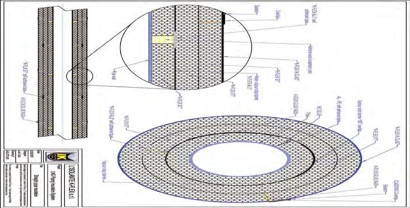
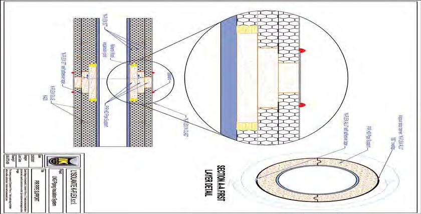
2 LNG applications Manual The insulation LNG plants may forsee a multilayer design according to the specific characteristics and the working temperatures of the plants that need to be insulated. In order to establish the correct scale of the insulation, always refer to the project specifications and to the specific K-FLEX IN CLAD Piping Equipment Insulation Specification attached to this document. L ISOLANTE K-FLEX
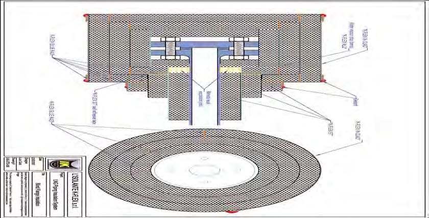
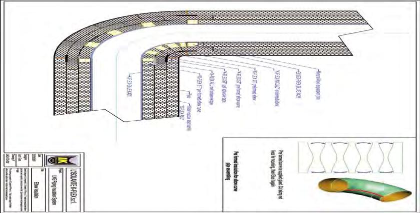
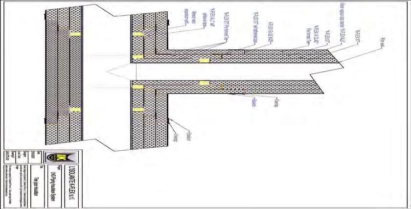
3 indice TOOLS NEEDED TO CARRY OUT THE INSULATION ACCESSORIES INSTALLATION INSTRUCTIONS PREPARATIONS BEFORE STARTING MULTILAYER INSULATION, PIPES First layer Middle layers Installation K-FLEX IN CLAD covering Pipe supports MULTILAYER INSULATION, SPECIAL PARTS Preformed T connection, first layer Making the T connection sections on-site from sheets Making the vapour barrier on the T connection Preformed elbows: first layer Elbows and T connections. Following layers (applies to the two, three or more layer designs) Flanges Insulation of the valves Fixing the K-FLEX IN CLAD covering onto the T connection Fixing the K-FLEX IN CLAD covering on flanges Fixing the K-FLEX IN CLAD covering on valves SPECIAL PREFORMED MULTILAYER SECTIONS LIST OF DRAWINGS STRAIGHT PIPE PIPE SUPPORT FLANGE BLIND FLANGE END CAP ELBOW T CONNECTION CONCENTRIC REDUCTION TECHNICAL SPECIFICATIONS

4 general principles 1 LNG insulations are all multilayered 2 The first layer is never glued 3 The joints of the first layer always have an expansion joint 4 The first layer is always covered with an aluminium/polyester vapour barrier 5 The first layer does not adhere perfectly to the pipe: an excess of 2-5% is necessary to allow for thermal contraction of the insulation during use 6 The following layers are installed in the same way as those for traditional applications for cold (glue and anticondensation tape on all joints and staggering of the joints between the various layers


5 tools needed for the job compass brushes spatula marker pen 4
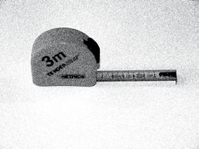
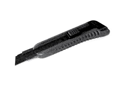


6 knife-shapening stone scissors ruler knife scalpel compass to measure diameters chalk sand paper 5


7 accessories TAPE, COVERING AND AdHesivES L ISOLANTE K-FLEX advises using two types of tape: K-FLEX ST anticondensation tape and K-FLEX ALU AA 130 tape. ANTICONDENSATION TAPE Measurements Thickness mm: 3 Lengths m: 10, 15 Widths mm: 50, 75, 100 ALU AA 130 Tape Self-adhesive joint covering tape in smooth aluminium Measurements Thickness: 30 µ Length m: 50 Widths mm: 50, 75, 1000 K-FLEX in clad tape Measurements Thickness: 1 mm Length m: 25 Widths mm: 50, 100 alu 5 layer foil Measurements Thickness: 80 µ Length m: 100 Width mm: K-FLEX IN CLAD covering Measurements Thickness mm: 1 Length m: 10 Width mm:


8 TUBES thickness mm 9 thickness mm 13 thickness mm 19 thickness mm 25 thickness mm 32 thickness mm 40 INDICATED CONSUMPTION OF 1 LITRE OF ADHESIVE glued to the heads every m every 500 m every 300 m every 220 m every 180 m every 139 m L'ISOLANTE K-FLEX does not accept responsibility for consumptions that may differ to those indicated above glued lengthways every 150 m every 100 m every 80 m every 60 m every 40 m every 27 m K-FLEX ADHESIVES K-FLEX K 420 glue has been specifically designed for use with K-FLEX elastomeric foam insulation material. The securely bonded surfaces and joints are resistant to ageing and atmospheric agents and preserve the technical characteristics of the insulating material. K 420 ADHESIVE in tins of: 0, ,6 litres marine sealant Marine sealant is suitable for making elastic constructive joints and has extremely good UV-resistance and ageing properties. Product is based on Silyl Modified Polymers. Packaging: cartridges 290 ml SPECIAL K-FLEX THINNERS Before covering the surfaces to be insulated, it is advisable to clean them thoroughly with the special K-FLEX thinners. 1 LITRE TINS 7
9 INSTALLATION INSTRUCTIONS 9
 STAGGERED LAYERS.")
 are always staggered in order to ensure that the edges are never aligned. In this way, starting to insulate from the pipe supports (fig.")
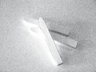
 prepare several 30 mm thick mineral")
 The mineral fibre strips should each be cut to a width of 50 mm. This material will be used for making the compensation joints, (figs. from 2-4).")


 Cut a strip of K-FLEX ST elastomeric material of about 100 in width, fig. 5.")
10 PreparaTION BEFORE STARTING TO INSULATE cleaning the surface to insulate. Thoroughly degrease the surface to be insulated with the producer s specified thinners 2) STAGGERED LAYERS. The insulation must be carried out, making sure that the end joints of tubes (preformed up to a diameter of 168 mm) and of sheets (for diameters from mm) are always staggered in order to ensure that the edges are never aligned. In this way, starting to insulate from the pipe supports (fig. 1) where the sections are already staggered, the next layers are applied with end joints that are not aligned. 3) compensation joints. Prepare a sufficient quantity of mineral fibre compensation joints according to the following indications: a) prepare several 30 mm thick mineral fibre strips; b) cut sections with the same width as the insulation s thickness eg. 50 mm thickness, (fig. 2). c) The mineral fibre strips should each be cut to a width of 50 mm. This material will be used for making the compensation joints, (figs. from 2-4) making the right size tubes from sheets The insulation of the pipes can be carried out using preformed tubes, cut out from sheets, or, when working on-site it is possible to use sheets for insulating pipes of large dimensions. Usually preformed insulating tubes are used for diameters from mm whereas for greater diameters it is easier to use sheets cut to size, as indicated further on in the manual, in order to obtain the desired result, or one can even order the sheet section already prepared for installing. a) Cut a strip of K-FLEX ST elastomeric material of about 100 in width, fig. 5. b) With the strip, measure the circumference of the pipe to insulate and make a mark on the strip to indicate the correct circumference. Add to this measurement an excess of 3% (fig. 6). NB: Gently lay the strip onto the tube. Do not stretch, avoiding ending up with a section which is too short. c) Lay the K-FLEX insulation sheet onto a flat surface and use the previously cut strip to obtain the sheet sections needed to insulate the pipes, (figs. 7-8). 10
 apply the tube sections, previously cut out of a sheet, onto the")
 Seal the insulation together with 50 mm ALU AA 130 self-adhesive tape, attaching strips")
 To make sure that the ALU AA 130 tape is correctly placed, press together the logitudinal")
 Once the tape is fixed perpendicularly, apply the tape along the complete length of the")
 Rotate the logitudinal seal downwards, turning the insulation 180 to position the tube s")

11 MULTILAYER INSULATION, PIPES FIRST LAYER ApplYING THE FIRST LAYER a) apply the tube sections, previously cut out of a sheet, onto the pipes. b) Seal the insulation together with 50 mm ALU AA 130 self-adhesive tape, attaching strips every 30 cm perpendicularly to the cut, (fig. 9). c) To make sure that the ALU AA 130 tape is correctly placed, press together the logitudinal edges of the insulation so that they touch and securely fixdown the tape, (fig. 10). d) Once the tape is fixed perpendicularly, apply the tape along the complete length of the tube to be insulated, over the joint, (fig. 11). e) Rotate the logitudinal seal downwards, turning the insulation 180 to position the tube s sealed joint towards the ground Installing the compensation joints Between each insulated section, add a strip of previously prepared mineral fibres, see pag. 10. a) position the strip between the insulated tube sections, (fig. 12). b) It is advisable to install the elastomeric material so that they come into contact and then, using force, insert the mineral fibres strip between the end joints, (figs ). 11
 From a roll of ALU 5 layer foil,")

 Apply the sheet of ALU 5 layer foil onto")
.")
12 MULTILAYER INSULATION, PIPES FIRST LAYER vapour barrier a) From a roll of ALU 5 layer foil, cut out a sheet with a width equal to one and a half times the circumference of the insulated tube, (figs ) b) Apply the sheet of ALU 5 layer foil onto the K-FLEX insulation, securely fixing it down to obtain a tight fitting cover, (figs ). All the edges of the vapour barrier must be staggered. 12


13 MULTILAYER INSULATION, PIPES FIRST LAYER c) It is important to stagger the edges of the insulation and the edges of the ALU 5 layer foil in order to avoid continuity with the underlying edge. Every sheet of ALU 5 layer foil should be positioned in such a way as to overlap the following one by at least 100 mm between one section and another. d) On both the longitudinal and end joints apply 50 mm ALU AA 130 selfadhesive tape to fix down the vapour barrier, (figs ). 13


. 4.")


14 MULTILAYER INSULATION, PIPES middle layers Indications for cutting sheets to size 1. Repeat the procedure described above for carrying out the insulation of the following layers, without adding any excess during the preparation of the sheet sections. 2. Take care not to overlap the expansion joints of the following layers. 3. Use K-FLEX K-420 adhesive for sealing both the longitudinal and end joints of both the sheets and tubes, applying the glue with a brush on both the sides to be sealed. Wait until the glue dries before installing the insulation material, (figs ). 4. Install the insulation on the tube, taking care to avoid positioning the joints above those of the underlying layer. (first or second layer), (fig.25) a 27b 5. Apply, only on the second layer, 50 mm K-Flex anticondensation tape on all the longidudinal and (fig. 26) head joints which were previously glued together, (fig. 27). 6. For layers applied after the second one, it is not necessary to use (figs b) anticondensation tape. 14

 Position the K-FLEX IN CLAD on the area where the glue has been applied and from that point wrap the K-FLEX IN CLAD sheet around the whole section.")
 With a brush, apply K-FLEX K-420 adhesive on both ends in order to obtain a perfect seal against water between the covering and the insulation material, (figs. 30-32).")
15 MULTILAYER INSULATION, PIPES installing the K-FLEX IN CLAD covering PreparaTION OF IN-CLAD From a roll of K-FLEX IN CLAD, cut a sheet with the same width as the circumference of the insulated tube, adding an excess of roughly 50 mm for the longitudinal overlap. 2. Installation a) Apply a layer of K-FLEX K-420 glue along the section of the tube to be covered with K-FLEX IN CLAD. b) Position the K-FLEX IN CLAD on the area where the glue has been applied and from that point wrap the K-FLEX IN CLAD sheet around the whole section. c) Securely press down the K-FLEX IN CLAD covering along the whole circumference, in order to obtain a tightly fitting cover, fig. 29. d) With a brush, apply K-FLEX K-420 adhesive on both ends in order to obtain a perfect seal against water between the covering and the insulation material, (figs ). NB: Take care to stagger the edges of the insulation and the the edges of K-FLEX IN CLAD to avoid continuity with the underlying edge. Each sheet of K-FLEX IN CLAD should be positioned in such a way as to overlap the next sheet by at least 50 mm. Use K-FLEX K-420 on both the longitudinal and transverse overlaps Sealing with marine sealant In order to obtain a covering with a secure water barrier, use marine sealant approved by L ISOLANTE K-FLEX on all the joints: - Between all the longitudinal and transverse overlaps of the K-FLEX IN CLAD covering - Betwen the pipe supports and the K-FLEX IN CLAD covering - Between the overlaps of the valves, flanges, T connections and terminals - On the sections of the elbow covered with K-FLEX IN CLAD - On all the overlaps and K-FLEX IN CLAD joints. Proceed as follows on all the joints indicated in figures 33 and 34: a) with the corect dispensor, spread a layer of marine sealant at least 10 mm wide, (figs ). b) check that there are no breaks in the seal c) carefully follow the instructions indicated on the tin of sealant and check the time required to obtain a secure and permanent seal. 15
 On a work surface, position all the shell sections needed for")
 On the tube, apply an elastic band as shown in figure 36, which will help to hold the shells onto the tube.")
 Use the correct tools at the ends of the pipe support (10 cm from the right and left edges) to secure the support onto the tube, using sufficient")
.")


 For all the following layers (fig.")
16 MULTILAYER INSULATION, PIPES pipe supports Pipe Supports For a correct installation of the PU pipe supports, proceed as follows: a) On a work surface, position all the shell sections needed for the pipe support b) Apply Foster putty on the edges of the PU shell sections, (fig. 35). c) On the tube, apply an elastic band as shown in figure 36, which will help to hold the shells onto the tube. d) Apply the support sections one at a time starting from the top and continuing in a clockwise direction, rotating then downwards, (fig. 37). e) Use the correct tools at the ends of the pipe support (10 cm from the right and left edges) to secure the support onto the tube, using sufficient force in order to achieve a tight fit of the longitudinal shell sections. Position two aluminium sheets under the jack to avoid ruining the supports, (fig. 38). f) Wrap around the appropriate reinforced fiberglass tape three times in the following three positions, (fig. 39). - On the side of the left jack towards the centre, at about 10 cm - On the side of the right jack towards the centre, at about 10 cm - At the centre of the pipe support g) Remove both left and right jacks. Proceed in the same way for the following layers taking care to: - apply the vapour barrier on the first layer, leaving 100 mm of overlap on each side, and apply 1,5 rotations of ALU 5 layer foil. Finally, seal the vapour barrier with reinforced fiberglass tape, (fig. 40). h) For all the following layers (fig. 41) of the pipe support, the vapour barrier should be positioned only when the installer has attached the metal collars, (fig. 42); afterwards, proceed with the covering as follows: - Measure the distance between the end of the metal collar and the pipe support, add 50 mm of excess for the overlap and cut out a strip of K-FLEX IN CLAD. - Install this strip, taking care to glue the longitudinal and transverse overlaps with K-FLEX K 420 adhesive. - Apply marine sealant to all the joints around the pipe support. - to avoid water infiltrations, cover all the openings around the supporting collar with marine sealant, (fig. 42). 16
. Cover everything with the vapour barrier as shown in figure 44.")
.")
 Cut a section of K-FLEX IN CLAD equal to the external circumference of the pipe support, plus 50 mm of longitudinal and transverse excess on all sides, (fig. 46).")
17 MULTILAYER INSULATION, PIPES pipe supports Connection between the pipe support and the tube sections a) First layer On the edges, apply mineral fibre strips as previously carried out for the elastomeric material, (fig. 43). Cover everything with the vapour barrier as shown in figure 44. b) Following layers Glue the two ends of the supports to the elastomeric material using K-FLEX K-420 adhesive. Only on the second layer, apply 50 mm K-FLEX anticondensation tape on all the glued joints, (fig. 45). In a three layer installation, on the third layer, it is not necessary to apply anticondensation tape. K-FLEX IN CLAD covering The pipe supports should be covered externally with K-FLEX IN CLAD. Proceed as follows: a) Cut a section of K-FLEX IN CLAD equal to the external circumference of the pipe support, plus 50 mm of longitudinal and transverse excess on all sides, (fig. 46) b) Wrap the covering around the pipe support, (fig. 47). c) Apply K-420 glue on both the longitudinal and transverse overlaps of the K-FLEX IN CLAD covering and also onto the areas below onto which the overlaps will be glued, (fig. 48). d) Join together the areas to be glued and apply enough force to ensure a perfect sealing, (fig. 49). Coverings On both sides of all joints, apply a 10 mm layer of marine sealant, (fig. 50). 17


, fixing them together with 50 mm ALU AA 130 self-adhesive tape along")

 ALU AA 130 self-adhesive tape should be applied as shown in figures 55")

18 preformed T connections, 1 layer T connections first layer with T connection in sections ready for installing The T connection is made of two pieces ready for installation as shown in figure 51. As previously indicated for straight sections, the installation should be carried out following the multilayer design. The first layer must never be glued; ALU AA 130 tape will be used to fix the T connection sections to the pipe. Proceed as follows. a) On the tube, apply the single precut T connection sections (fig. 51), fixing them together with 50 mm ALU AA 130 self-adhesive tape along all the joints (figs. 52, 53, 54). NB: first install the horizontal section (figs. 52 and above) followed by the vertical one (fig. 64 and following). b) ALU AA 130 self-adhesive tape should be applied as shown in figures 55 to NB: The ALU AA 130 tape should be applied both longitudinaly and transversely over the joints, as shown in figures 52 to 58. NB: The prepared T connection sections needed for the installation are already supplied with a 3% excess. During the installation, this excess should be maintained. Therefore only seal down what is necessary. 18
19 preformed T connections, 1 layer d) With controlled pressure, insert the mineral fibre strips into the joints as shown in figure 59. e) When this operation is complete, the T connection should now appear as shown in figure

 Horizontal section Prepare a strip of K-FLEX ST elastomeric material about 100 mm wide, with the same thickness")

.")
 to obtain the radius needed to trace two semi-circles with a compass, (fig. 65).")
 should be equal to 3 times that of the measured radius in figure 74.")
20 making the t connection sections on-site from sheets The T connection sections can be easily made directly on-site by cutting them out of a section of K-FLEX ST sheet. They should be made in two sections, a horizontal and vertical one, (fig. 51). Proceed as follows. a) Horizontal section Prepare a strip of K-FLEX ST elastomeric material about 100 mm wide, with the same thickness as the insulation which will be used, in order to take the measurements of the circumference, fig. 61. Do not stretch the strip, avoiding creating a section that could be too short. Finally, add an excess of 3%. - Transfer the measurements onto a K-FLEX ST sheet as indicated by the red arrow in figure 75 for preparing the length. - Measure the diameter of the T connection, (fig. 62). - Transfer the measurements of the diameter onto a ruler, (fig. 63). - Divide the measurement by 2 (fig. 64) to obtain the radius needed to trace two semi-circles with a compass, (fig. 65) The width of the sheet (green arrow in fig. 65) should be equal to 3 times that of the measured radius in figure 74. Whereas the length, as previously indicated, is the same as the circumference of the T connection section, as indicated in figure Once the two semi-circles have been marked out with the point of a compass (fig. 67), start to cut them out along the lines with a sharp knife, (fig. 68). 20


.")


21 making the t connection sections on-site from sheets Apply the horizontal section of the T connection onto the pipe, (fig. 69). - Fix the horizontal section together using ALU AA 130 tape as indicated in figures 70 to Preparing the vertical section To prepare the vertical section of the T connection, proceed as follows: - Take the measurements of the coupling arm section by resting the cut sheet on it to use as a basis for measuring, (fig. 73). - Divide a second K-FLEX ST sheet into four equal sections, using the same method as indicated in figure 61. Draw a line parallel to the edge. The distance from the edge must be equal to that of the difference in height measured in figure 85. This line is needed to obtain the intersecting point with the three previously drawn vertical lines to use as the center for the following circles, (figs ). 21


.")
22 making the t connection sections on-site from sheets At this point, with the help of a metal ruler, trace 4 sections as indicated in figures 78 and With a white felt pen, draw a median line which exactly divides in two the previously drawn section, (fig. 80). - Finally draw the curves as indicated in figures 81 and Fig Fig Fig cut out the final shape following the lines, (fig. 83). - Measure the distance between the horizontal T connection section and the next already installed section, (fig. 84). Transfer the measurements onto the sheet (fig. 85) and cut out the horizontal section of the T connection, which is now ready to be installed. 22


23 making the t connection sections on-site from sheets Install the section onto the pipe, fixing it together with 50 mm ALU AA 130 self-adhesive tape, as indicated in figures 86 to 90. NB: The ALU AA 130 tape should be applied both transversely (figure 103), and longitudinaly to the cut as shown in figure Apply, in the intersection between one sheet and another, a 30 mm thick strip of mineral wool; with the same thickness as the insulation which will be used. - Proceed to cut a few strips of mineral fibre as indicated in figure 105 and previously on page 20, and insert them between the intersections as seen in figures 91 and 92. NB: Bearing in mind the function of these strips (to compensate for the contraction of the elastomeric sheet), it is advisable to install the elastomeric material so that they come into contact, and then, using force, open them apart to allow enough space for the wool. 23


.")


24 APPLYING the vapour barrier on the T connection Prefabricated VAPOUR BARRIER - On the first insulated layer, apply the prefabricated, ALU 5 layer foil sections of the T connection, (fig. 93). - Apply the vapour barrier securely, in order to obtain a tight fitting cover which compensates for the 3% of excess previously added to the insulation, (figs ). - Cover each overlap with 50 mm ALU AA 130 self-adhesive tape, (figs ). The final result will result in a perfect vapour barrier, (fig. 100) making the vapour barrier on-site Prepare the sections which will be applied to the insulation by cutting them out of a sheet of ALU 5 layer foil, following the instructions indicated in the previous pages for making the T connection with K-FLEX insulation. Apply each sheet of 5 layer aluminium foil onto the insulation, fixing them down securely in order to obtain a tightly fitting cover and to compensate for the 3% of excess previously added to the insulation. Take care to stagger the edges of the insulation and the edges of the ALU 5 layer foil sheet to avoid continuity with the underlying edge. Every sheet of ALU 5 layer foil should be positioned in such a way as to overlap the following sheet by at least 100 mm. On both the longitudinal and tranverse overlaps, 50 mm ALU AA 130 selfadhesive tape should be used. 24

.")


25 preformed elbows: first layer a) first layer: elbow in sections - The first layer of the elbows must be constructed using precut sections, ready to be installed, (fig. 1). - On the pipe, apply the single precut elbow sections previously cut out of a sheet of K-FLEX ST, closing them together with 50 mm ALU AA 130 selfadhesive tape along all the joints, (figs. 2-3) Repeat the operation and proceed to apply all the elbow sections. NB: The elbow sections which have a straight side, the ones at the start and at the end, can be used in a specular way, (fig. 1). - Continue to apply ALU AA 130 self-adhesive tape to close all the sections, as shown in figures


 vapour barrier - On the insulated first layer, apply")
, taking care to overlap each segment over the previous one by")

26 preformed elbows: first layer 8 9 b) compensation joints - Insert a mineral fibre strip (see previous pages for indications on how to make mineral wool strips) between each section of the elbow. NB: When this operation is complete, the elbow should resemble the photo in figs. 9 (detail) and 10 (complete elbow). 10 Fig.20 Fig c) vapour barrier - On the insulated first layer, apply the prefabricated elbow sections in ALU 5 layer foil (fig. 11), taking care to overlap each segment over the previous one by at least 50 mm. - Attach them securely, in order to obtain a tight fitting cover and close each section with ALU AA 130 self-adhesive tape, (fig. 12). 26


.")

27 preformed elbows: first layer Repeat the previously indicated operations for all the elbow sections, (figs. 20 and 21). Cover each overlap with 50 mm ALU AA 130 self-adhesive tape, (fig. 16). 27

.")

 Mount the elbow onto")
 Starting from the two extremities,")

 Apply K-Flex K-420 glue on both the")
28 elbows and t connections: following layers elbows With preformed elbows: a) Cut the preformed elbow along the lower spine, (figs ). b) Apply K-FLEX K 420 glue on the cut edges and wait until the glue is almost dry, (fig. 21) c) Mount the elbow onto the tube, (fig. 20). d) Starting from the two extremities, glue the joints together. Make sure that both sides are well glued, also internally, (fig. 22). e) Apply K-Flex K-420 glue on both the lateral edges and wait until the glue is almost dry, (fig. 23). 28
.")


.")


.")
.")
29 elbows and t connections: following layers f) Next, apply 50 mm K-FLEX anticondensation tape over all the glued joints, (figs ). Preparing the elbows on-site from sheets - First of all, measure the internal radius of the curve using a ruler with another ruler lying perpendicular to it, as shown in figure Using a compass, mark out the outline of the internal radius on the K-FLEX sheet, using the corner of the square marked out on the insulating material as the axis, (fig. 27). - measure the exact circumference of the pipe using a strip of K-FLEX ST sheet of the correct thickness and divide the circumference by two, and mark the middle of the strip accordingly. - Add the outer radius to the measurement of the inner radius and, using the same axis, mark out a semicircle onto the sheet with the compass, (fig. 28). - Cut the sheet accurately along the arc of the circle, (fig. 29). - Place the section obtained on the reverse side of another sheet and use it as a template to cut out a second, mirror image section, (fig. 30). - Allow the glue to dry and stick the edges together, starting from the two extremities. - Finally, install the elbow and follow the same procedures already indicated for preformed elbows, (figs ). 29

.")


30 elbows and t connections: following layers Fig.31 Fig Installation of the 3 elbow layer Proceed to install the third layer of the elbow as previously indicated for the second layer (both for preformed elbows and elbows cut out of sheets on -site). NB: In the third layer do not use K-FLEX ST anticondensation tape. It is only necessary to: - Install the elbow - Glue the joints with K-FLEX K-420 adhesive, (figs ). Installation of the second T CONNECTION layer - The installation of the second T connection layer must be carried out with the same procedure as previously indicated on pages 19 and 25, both for preformed T connections and for those made directly on-site from sheets However, there are certain aspects to take into consideration: 1. K-FLEX K-420 glue, which was not used on the first layer, must be used on all the joints of the T connection. - Apply ST anticondensation tape over all the joints as indicated in figures 37 and 38. At this point the T connection is ready to be covered with K-FLEX IN CLAD, or in the case of the three layer design, the third elastomeric layer can now be installed. The procedure to follow for the third elastomeric layer is exactly the same as that indicated for the second layer except that ST anticondensation tape should not be applied. 30


31 elbows and t connections: following layers Application of the third T CONNECTION layer - As previously indicated, the application of the third layer differs from that of the previous one in as much as it is not necessary to apply ST anticondensation tape on the joints. The photos from 39 to 41 show the T connection insulated with 3 layers. 31

.")


.")
.")
.")
32 flanges installation of the first layer of the flange cover - Measure the pipes circumference. Use the measurements of the two diameters to calculate the respective inner and outer radii, (fig. 42). - After calculating the two radii, mark out the inner and outer circumferences of the rings on two separate squares of K-FLEX ST sheet. - Attaching a sharp blade to the tip of the compass allows the first incision to be made so that a knife can then be used to cut out the ring. However, a knife alone can give acceptable results, (fig. 43). Cut the rings out and make an opening on one side to attach them around the pipes, (fig. 44). Use Alu AA 130 tape to secure the ring onto the flange, (fig. 45). Complete the insulation of the tubes on the left and right sides of the flange as indicated in the above figures, (figs 46-47) Repeat the same operation for the other side of the flange, (fig. 48). - Apply a strip of mineral fibres between the rubber ring and the pipe as shown in figures Measure the distance between the two rings, including the thickness of the insulating material, (fig. 49). 32


.")

33 flanges Use a strip of K-FLEX ST sheet of the same thickness to measure the circumference of the insulating rings, (figs ). - Transfer the measurements onto a K-FLEX sheet to obtain the outline of the sleeve that will complete the flange s insulation. - Mount it around the rings and tape together the edges, (fig. 51). - Fix it securely with Alu AA 130 tape as indicated in figure installing the vapour barrier Measure the circumference of the insulated flange and the tube section, (figs ). 33


.")
.")


34 flanges Transfer the measurements onto a sheet of ALU 5 layer foil using a compass as shown in figure With the compass, add 5 cm for the overlap and draw the circle, (fig. 56). - Make perpendicular internal and external cuts with a pair of scissors, (fig. 57). - Make a cut as indicated in figure 58 and apply the vapour barrier onto the flange as shown in figure Repeat the same operation for the other side of the flange. - Seal everything using Alu AA 130 tape, (fig. 60). - Finish the vapour barrier with Alu AA 130 tape as indicated in figure


35 flanges SECOND FlangE LAYER - Repeat the operations previously carried out for the first layer to create the second layer of the flange cover, (fig. 62). - Use K-FLEX K-420 glue to seal together the second layer of the flange cover, (figs ). - Apply K-Flex ST anticondensation tape over all the joints, (figs ) Once the ST anticondensation tape has been applied, the insulation of the flange should appear as in figure 66. insulation of the 3 FLANGe layer To apply the third insulation layer on the flange, follow the same procedure indicated for the application of the second layer. However in this case it is not necessary to apply K-FLEX ST anticondensation tape. To seal the flange cover, as indicated for the second layer, use K-FLEX K-420 glue. 35


. - Carefully cut out the rings.")
. 73.")


36 insulation of the valve insulation of the valves - Measure the diameter of the pipes and the flanges. Use these measurements to calculate the relevant radii, (fig. 70). - After calculating the radii, mark out the respective inner and outer circumferences on two separate squares of K-FLEX ST sheet of the same thickness, (fig. 71). - Carefully cut out the rings. - Make an opening so that they can be fitted over the pipes. - Place a ring on the outside of the valve, (fig. 72) Fix the ring onto the valve with AA 130 tape as shown in figure 73 - Apply a strip of mineral fibre between the ring and the flange, (fig. 74). - Apply a strip of K-FLEX ST sheet around the top part of the flange as indicated in figure 74 and fix it with ALU AA 130 tape. - Next, calculate the shape of the disc for the top of the flange. - Measure the circumference of the supporting flange and the form of the face plate around which the disc must fit. Mark out the measurements on a section of of K-FLEX ST sheet and cut the disc out, (figs ). 36
.")


.")


37 insulation of the valve Make an opening so that the disc can be fitted over the face plate, (fig. 78). - Position the disc over the face plate. - Draw the outline of the sleeve section measurements onto a sheet of K- FLEX ST sheet and draw a line down the middle. - Measure the diameter of the stopcock housing. - Divide the diameter by two to obtain the radius. Place the compass at the end of the sleeve s center line and draw a semicircle at each end, (fig. 80) If there are any imperfections along the cut edges, smooth them out so that they precisely bond together. - Fix the valve s cover with Alu AA 130 tape, (fig.82). APPLYING THE VAPOUR BARRIER ONTO THE valve COVER FIRST LAYER The insulation of the valve on the first layer should be completed with the vapour barrier made from ALU 5 layer foil. As already indicated in the previous sections for making the vapour barrier, proceed as follows: - measure the internal and external diameters of the sides of the valve, (fig. 83). - transfer these measurements onto a sheet of ALU 5 layer foil (see figures 55 to 58 on page 34) and cut out the covers in aluminium as shown in figure

.")


38 insulation of the valve Position the previously prepared rings onto the left and right side and also onto the cover of the valve, (figs ). - take the measurement as indicated in figure 87 in order to prepare the second section of the vapour barrier. - transfer the measurements onto a sheet of ALU 5 layer foil and cut out the shape using a pair of scissors Once this section of the vapour barrier has been cut out, it should have the same shape as shown in figure Finally proceed to install this section onto the valve as shown in figure Fix this section of the vapour barrier onto the valve with ALU AA 130 tape, (figs ). 38


.")


39 insulation of the valve Proceed to insulate the right and left tube sections of the valve with the vapour barrier (already insulated with the first layer of K-FLEX ST). - Measure the valve section which still needs to be covered with the vapour barrier, (fig. 103). - From a sheet of ALU 5 layer foil, cut out this section of the vapour barrier and position it onto the valve, (figs ). - Fix everything together with ALU AA 130 tape, (fig. 106)


 The T connections are made in three pieces")


 Once the K-FLEX IN CLAD covering is")
.")
40 FIXING THE K-FLEX IN CLAD COVERING ONTO THE t CONNECTION fixing the K-FLEX IN CLAD covering onto the t connection a) Thoroughly degrease each section of the prefabricated K-FLEX IN CLAD T connection with the correct thinners. b) The T connections are made in three pieces which should be directly applied onto the elastomeric sections. First install the main section of the T connection followed by the coupling sections. c) Apply K-FLEX K 420 glue, as shown in figures 20 onwards, both to the elastomeric material and the K-FLEX IN CLAD covering d) Once the K-FLEX IN CLAD covering is positioned onto the insulation, carefully seal all the overlaps with K-FLEX K 420 glue, (fig. 6). e) Finally, press the overlaps down with force to make sure that both surfaces firmly adhere together, (fig. 8). 40
 Proceed")

 Finally, spread glue over all the")
 The T connection is now ready to be")
")
 Proceed")
 Marine sealant should be applied to")
41 FIXING THE K-FLEX IN CLAD COVERING ONTO THE t CONNECTION f) Proceed to apply the K-FLEX IN CLAD covering onto the coupling, repeating the same procedure as before, (figs. 9 and 10). g) Finally, spread glue over all the joints, (fig. 11). e) The T connection is now ready to be sealed with marine sealant, (fig. 12) applying marine sealant: a) Apply a 10 mm layer of marine sealant on both sides of all the joints b) Proceed carefully as indicated in figures c) Marine sealant should be applied to all joints as can be seen in figure
 measure the")
 using a compass, mark out the internal and external measurements")

 using a sharp knife, cut around the furthest circle to obtain the")
 The disk is now ready to be")
 Repeat the same operation to cover the other side of the flange.")
42 fixing the K-FLEX IN CLAD COVERING on the FLANGE APPLYING THE K-FLEX IN CLAD COVERING ONTO THE FLANGE a) measure the internal and external diameters of the flange, (fig. 17). b) using a compass, mark out the internal and external measurements onto a sheet of K-FLEX IN CLAD. Add an excess of 5 cm to the external diameter and trace a third circle, (fig. 18). c) using a sharp knife, cut around the furthest circle to obtain the disc d) Make external and internal fringes on the disk as indicated in figures 19 and 20 e) The disk is now ready to be mounted onto the flange, (fig. 18). f) Repeat the same operation to cover the other side of the flange. g) Make an opening cut on the disk and slot it onto the flange, (fig.19). h) Use K-FLEX K-420 glue to fix the disk onto the flange, (figs ). 42
 tightly close the")

 When installed, the disk should appear as")
 Proceed by measuring the central section")
 Transfer the measurements onto a sheet of")
.")

 Place the previously prepared strip of")
43 fixing the K-FLEX IN CLAD COVERING on the FLANGE i) tightly close the fringes of the disc, which have already been glued with K-FLEX K-420, in order to obtain a perfect grip. j) When installed, the disk should appear as in figure 23. k) Proceed by measuring the central section of the flange, (fig. 24). l) Transfer the measurements onto a sheet of K-FLEX IN CLAD and cut out the required section, (fig. 25) m) spread K-FLEX K-420 glue on the elastomeric material and wait until it is almost dry. n) Place the previously prepared strip of K-FLEX IN CLAD onto the flange. o) To correctly attach the K-FLEX IN CLAD sheet, use K-FLEX K-420 glue and allow it to almost dry before sealing down both edges. 43
 Proceed carefully as indicated in figures 38-40 of the following page.")
44 fixing the K-FLEX IN CLAD COVERING on the FLANGE applying marine sealant: a) Spread a 10 mm layer of marine sealant over both sides of all joints. b) Proceed carefully as indicated in figures of the following page. 44


 After appling the K-FLEX K-420 glue, wait until")

 K-FLEX K-420 glue.")

45 fixing the K-FLEX IN CLAD COVERING on the elbows APPLYING K-FLEX IN CLAD COVERING ONTO THE ELBOWS a) Apply the preformed K-FLEX IN CLAD elbow segments onto the elbow by sealing them onto the elastomeric material with K-FLEX K- 420 glue. b) After appling the K-FLEX K-420 glue, wait until it is almost dry before fixing the segments onto the elbow. c) The elbow segments should be fixed onto the throat with (figs.33 and 34) K-FLEX K-420 glue applying: a) Spread a 10 mm layer of marine sealant over both sides of all joints. b) Proceed carefully as indicated in figures


 Mark the two different measurements on the dividing lines")
.")


.")
46 fixing the K-FLEX IN CLAD COVERING on the valve IN-CLAD covering: Valves To fix the K-FLEX IN CLAD covering on valves, proceed as follows: a) Measure the distance between the disc and the existing lagging at its nearest and furthest point, (fig. 1). b) Mark the two different measurements on the dividing lines of the tracing, as illustrated, then draw the intersecting lines from one extremity of the shape to the other, (fig. 2). c) Using the difference in the two lengths as a radius, draw circles around the ends of the lines. Using the arcs of the circles, draw a continuous line linking them up, as illustrated in figure d) Add a third line which will be used as a guide to make the fringes, (fig. 5). e) Proceed by making longitudinal cuts as shown in figure 6. f) Apply the K-FLEX IN CLAD covering as shown in figures 7 and 8. 46


 using a compass, mark out the measurements of both the internal and")

 using a sharp knife, cut out around the external circumference to obtain the disk.")
 The disk is now ready to be mounted onto the valve, (fig. 14).")
47 fixing the K-FLEX IN CLAD COVERING on the valve g) Use K-FLEX K-420 glue to fix the K-FLEX IN CLAD covering onto the insulation. h) Apply the glue onto both the K-FLEX IN CLAD covering and the insulation with a brush, (fig. 9). NB: Wait until the glue is almost dry before proceeding with the installation. PREPARING K-FLEX THE IN CLAd SIDE DISKS OF THE VALVE a) Measure the internal and external diameters of the valve b) using a compass, mark out the measurements of both the internal and external diameters onto a sheet of K-FLEX IN CLAD. Add 5 cm to the to the external diameter and trace a third circle which will be used for the overlap, (fig. 11). i) Using pressure, firmly seal down all the previously prepared fringes c) using a sharp knife, cut out around the external circumference to obtain the disk. d) Make internal and external fringes in the disk as indicated in figures 12 and 13. e) The disk is now ready to be mounted onto the valve, (fig. 14). f) Repeat the operation to cover the other side of the valve. g) Make an opening cut in the disk and slot it onto the valve. h) Use K-FLEX K-420 glue to seal the disc onto the valve, (fig. 15). 47
 Using pressure, fix down the disk")


 with a compass, take the measurements of the")

 With a sharp knife cut out the")
48 fixing the K-FLEX IN CLAD COVERING on the valve i) Using pressure, fix down the disk fringes, previously spread with K-FLEX K-420 glue, in order to obtain a perfect mechanical grip. j) When the disk is installed, it should appear as in figure 16. d) On the previously prepared K-FLEX IN CLAD disk, carefully draw out the protruding parts of the valve s cover, (figs ). K-FLEX IN CLAD valve cover Now proceed to make the valve cover with K-FLEX IN CLAD. a) with a compass, take the measurements of the valve s diameter b) transfer the measurements onto a sheet of K-FLEX IN CLAD. c) cut the disc as shown in figure e) With a sharp knife cut out the shapes and make an opening cut, (figs ). f) proceed to install the disk, sealing it onto the valve with K-FLEX K-420 glue. 48


.")


")

49 fixing the K-FLEX IN CLAD COVERING on the valve g) proceed by spreading K-FLEX K 420 glue over all the valve s K-FLEX IN CLAD joints, (figs ). h) Prepare a strip of K-FLEX IN CLAD sheet to apply around the valve s circumference as illustrated in figure i) Using K-FLX K-420 glue, seal the K-FLEX IN CLAD strip onto the valve. applying marine sealant a) Spread a 10 mm layer of marine sealant over both sides of all joints. b) Proceed carefully as indicated in figure

50 SPECIAL preformed MULTILAYER sections installing elbows, t connections, flanges and valves 50
 Open the sections 2) Install the first layer 3) Install")
 Install the K-FLEX IN CLAD covering 7) Apply marine sealant over all the")
51 PREFORMED T CONNECTION PREFORMED ELBOW PREFORMED FLANGE The special multilayer preformed sections must be installed in the following way 1) Open the sections 2) Install the first layer 3) Install the vapour barrier 4) Install the second layer using ST self-adhesive anticondensation tape 5) Install the third layer 6) Install the K-FLEX IN CLAD covering 7) Apply marine sealant over all the joints 51
52 list of drawings 53
53 54
54 55
55 56
56 57
57 58
58 59
59 60
60 61
K-FLEX K-FONIK INDUSTRIAL
 J a n u a r y 2 0 1 3 K-FLEX K-FONIK INDUSTRIAL Sound & Thermal Insulation design compliant with ISO 15665 www.kflexenergy.com Flexible Elastomeric Foam layer INSULATING PIPING WITH K-FLEX SHEETS > FIRST
K-FLEX K-FONIK INDUSTRIAL
 J a n u a r y 2 0 1 3 K-FLEX K-FONIK INDUSTRIAL Sound & Thermal Insulation design compliant with ISO 15665 www.kflexenergy.com INDEX INTRODUCTION: Standard for industry - ISO 15665................ Page
Sheet Insulation - Rectangular ducts. Installation Manual
 Sheet Insulation - Rectangular ducts Installation Manual 11 DISCLAIMER: The information in this document is based on our current state of technical knowledge. Due to the variety of possible influences
Edition Edition 2018 K-FLEX K-FLEX AL CLAD. Application manual
 Edition 2016 K-FLEX Edition 2018 K-FLEX AL CLAD Application manual K-FLEX AL CLAD APPLICATION MANUAL INDEX Introduction Pg. 3 Insulation of pipes Pg. 7 Insulation of elbows Pg. 10 Insulation of ducts Pg.
INDUSTRIAL SYSTEMS. Application Manual for Piping Equipment. ARMASOUND INDUSTRIAL SYSTEMS - Application Manual for Piping Equipment
 INDUSTRIAL SYSTEMS Application Manual for Piping Equipment INDEX Introduction................................ 2 Tools for Installing ArmaSound.............. 2 INTRODUCTION The advice contained within this
Pipe Supports Comparison
 PIPE SUPPORTS: Comparison of the installation costs for various systems ARMAFIX The easy to install and cost effective solution to prevent thermal bridging at the pipe bracket in low-temperature applications.
KoolthermTM. Installation Guide. HVAC & Building Services Pipe Insulation
 FM KoolthermTM Installation Guide HVAC & Building Services Pipe Insulation 2 Installation Guide This installation guide is an extract from the KoolthermTM FM Pipe Insulation Project Specification brochure
This specification describes the minimum requirements for industrial thermal insulation.
 016/09/7 1/7 1.0 PURPOSE This specification describes the minimum requirements for industrial thermal insulation. Read it in conjunction with the applicable insulation and insulation finish specifications
Fitting instructions
 Fitting instructions 2-3 TABLE OF CONTENTS Introduction 4 General fitting instructions 5 CLIMAFLEX accessories 6-7 Insulating during pipe fitting 8 Insulating after pipe fitting 10-11 Angles 12-13 Alternative
SPECIFICATION GUIDELINES FOR THE USE OF CRYOGEL Z ON COLD PIPING AND EQUIPMENT
 SPECIFICATION GUIDELINES FOR THE USE OF CRYOGEL Z ON COLD PIPING AND EQUIPMENT Page 1 of 15 Ver. 3-0 March 2010 TABLE OF CONTENTS 1. Scope... 3 2. General System Requirements... 3 3. Installation Details...
INSTRUCTIONS FOR LAYING
 PE moisture barriers are available in the following variants: PE 3/300 Original PE 3/300 Standard PE 3/300 RS Accessories system joint strip R300 system joint strip R300 Plus fixing tape sealing tape sealant
1/2 Ø. application manual
 1/2 Ø B H application manual >> ARMAFLEX application manual APPLICATION MANUAL application manual >> ARMAFLEX 1 GENERAL 3» Working with Armaflex 3» Tools for installing Armaflex 3» The correct use of Armaflex
How To Construct a Ferro Cement Tank
 How To Construct a Ferro Cement Tank Be Advised The following power point presentation assumes that individuals using it to construct ferro-cement tanks have a basic knowledge of geometry and calculating
BRANZ Appraisal Certificate # 461 (2010) Internal wet areas.
 Internal wet areas.") SPECIFICATION FOR PROTECTO WRAP AFM-WM FOR INTERNAL WET AREAS BRANZ Appraisal Certificate # 461 (2010) Internal wet areas AFM/WM INTERNAL 0104 Page 1 AFM-WM INTERNAL SPECIFICATION PRODUCT DESCRIPTION Anti
SPECIFICATION FOR PROTECTO WRAP AFM-WM FOR INTERNAL WET AREAS BRANZ Appraisal Certificate # 461 (2010) Internal wet areas AFM/WM INTERNAL 0104 Page 1 AFM-WM INTERNAL SPECIFICATION PRODUCT DESCRIPTION Anti
Gas Protection System Components
 Page 1 Visqueen Gas Protection Visqueen Building Products is recognised as the leader in the development, production and supply of high quality construction related ground gas protection membranes. The
Cold Work Cladding Fabrication & Application
 TRADE OF Industrial Insulation PHASE 2 Module 3 Substructures, Advanced Cold Work and Cladding UNIT: 4 Cold Work Cladding Fabrication & Application Produced by In cooperation with subject matter expert:
hüma PARKETTSYSTEM GmbH INSTALLATION GUIDE
 hüma PARKETTSYSTEM GmbH INSTALLATION GUIDE www.huema.co.uk Content Content GENERAL INFORMATION... 4 INSTALLATION NOTES... 6 ACCLIMATISATION... 6 CHECK FOR FAULTS IN THE MATERIAL... 6 REQUIREMENTS FOR
1. Division 23 Section "Hangers and Supports for HVAC Piping and Equipment" for pipe insulation shields and protection saddles.
 SECTION 23 07 19 - PART 1 - GENERAL 1.1 RELATED DOCUMENTS A. Drawings and general provisions of the Contract, including General and Supplementary Conditions and Division 01 Specification Sections, apply
adjustable fusion shower pan surface mounted on subfloor installation guide
 a a) Wall b) Tile c) Adjustable Shower Pan d) Liquid Membrane e) Crack Isolation Tape f) Cement Board g) Subfloor h) Joists b d c f h g e adjustable fusion shower pan surface mounted on subfloor www.trendingaccessibility.com
CONSTRUCTION SPECIFICATION FOR CHAIN-LINK FENCE
 ONTARIO PROVINCIAL STANDARD SPECIFICATION OPSS.PROV 772 NOVEMBER 2017 (Formerly OPSS 772, November 2012) Note: The PROV published in November 2017 replaces OPSS 772 COMMON, November 2012 with no technical
379 Quick Installation Guide
 Step 1: INSULATION 2212 W. 5th Pl., Tempe, AZ 85268 (480) 967-8888 379 Quick Installation Guide Step 2: Step 3: *see attached literature for complete installation instructions Remove and discard packing
079 Quick Installation Guide
 INSULATION 2212 W. 5th Pl., Tempe, AZ 85268 (480) 967-8888 Step 1: 079 Quick Installation Guide Step 2: *see attached literature for complete installation instructions Step 3: Position the next piece and
Installation Instructions for SuperFast Hurricane
 SuperFast Hurricane Installation Instructions for SuperFast Hurricane I. Before You Start / Preparations Please read all the instructions before you begin the installation. Improper installation will void
INSTALLATION. The no mess, fast and easy, Peel & Stick flooring underlay and installation system... Quick Glance - Features and Benefits
 The no mess, fast and easy, Peel & Stick flooring underlay and installation system... Ezy-Install is a new, environmentally friendly, acoustic underlay and flooring installation system with a unique Peel
FIRE STATION 55 June 14, 2010
 SECTION 15250 MECHANICAL INSULATION PART 1 - GENERAL 1.01 DESCRIPTION A. Work Includes 1. Insulation of Domestic Water Piping. 2. Pipe Insulation of refrigerant piping. 3. Insulation of ductwork. 4. Aluminum
Installation Instructions. Important. Recommended Tools. Palladium Rigid Sheet/Rubrail or Palladium G2 Sheet/Rubrail. Storage
 Important Storage Flat sheet - Store Palladium Rigid Sheet in a clean, dry, interior area at temperatures between 50 F and 95 F [10-35 C]. Keep out of direct sunlight. Make sure sheet is well supported.
1.2 The Engineer shall select appropriate sections of the specification to ensure that the specification is comprehensive for specified work.
 STAC Coating System Specification & Installation Guide 1.0 Scope 1.1 This specification may be used for the priming, caulking and wrapping with the STAC Petrolatum Coating System of any of the following
Design No. HI/BP PERIMETER FIRE BARRIER SYSTEM Hilti, Inc. ASTM E 2307 Table 1
 FIRESTOP JOINT SPRAY CFS-SP WB SILICONE JOINT SPRAY CFS-SP SIL F-RATING 2-HR. 2-HR. T-RATING -HR. -HR. APPLICATION THICKNESS PERIMETER FIRE BARRIER SYSTEM Hilti, Inc. ASTM E 2307 Table /8" WET FILM (/6"
INSTALLATION GUIDELINES for ISO-C1 POLYISOCYANURATE MECHANICAL INSULATION for CHILLED WATER SYSTEMS
 INSTALLATION GUIDELINES for ISO-C1 POLYISOCYANURATE MECHANICAL INSULATION for CHILLED WATER SYSTEMS Dyplast Products Copyright 2014 1 Rev 0414 DYPLAST PRODUCTS INSTALLATION GUIDELINES ISO-C1 POLYISOCYANURATE
INSTALLATION GUIDELINES for ISO-C1 POLYISOCYANURATE MECHANICAL INSULATION for CHILLED WATER SYSTEMS
 INSTALLATION GUIDELINES for ISO-C1 POLYISOCYANURATE MECHANICAL INSULATION for CHILLED WATER SYSTEMS Dyplast Products Copyright 2018 1 Rev 0618 DYPLAST PRODUCTS INSTALLATION GUIDELINES ISO-C1 POLYISOCYANURATE
KNOW-HOW. Quality characteristics of technical insulation materials: Fast and reliable installation is crucial
 KNOW-HOW Quality characteristics of technical insulation materials: Fast and reliable installation is crucial TIME IS MONEY Professional application is all-important in cold insulation. So installation
Solutions for industrial pipe work insulation
 Solutions for industrial pipe work insulation Technical Insulation November 2006 Prefabricated insulation components for superior pipe work insulation Pipes are a crucial component in industrial processes.
Laying Recommendations for Broadloom Carpet
 Laying Recommendations for Broadloom Carpet The information provided in these fitting instructions is general in its nature. Only through proper and expert laying in accordance with the "General Technical
Installation Guide. PAROC panel solutions
 Installation Guide PAROC panel solutions Panel System 4.00 INT January 2008 THESE INSTRUCTIONS ARE FOR NORMAL APPLICATIONS Work safety Preparation Wear protective gloves and clothing when handling the
PIPE AND EQUIPMENT INSULATION
 Contents (Click below to jump to section) Safety First 2 Material Handling 2 Preparation and Storage 3 Optimal Work Setup 4 Single Wrap Pipe 6 Double Wrap Pipe 7 Multi-Layer Wrap Pipe 8 Pipe Fittings 10
INSULATION. TROCELLEN SLEEVES Piping Application. Thermal Insulation
 INSULATION SLEEVES Piping Application Thermal Insulation Sleeves is an insulating material produced with chemically cross-linked closed cell polyolefin foam (a group which includes PE, PP, copolymers EVA
Insulation boards PhoneStar
 Sound Insulation Bavaria Insulation boards PhoneStar Installation instructions Wall Version 15.05. 2015 ONE solution universal in every area PhoneStar is an innovative, very efficient insulation board
ITW INSULATION SYSTEMS
 ITW INSULATION SYSTEMS 1SCOPE TRYMER RIGID POLYISOCYANURATE INSULATION IN LIQUEFIED NATURAL GAS APPLICATIONS (-260 F) 1.1 This guideline covers the installation of Trymer* Rigid Polyisocyanurate Insulation
Assembly Instructions
 QSM-BSB3 Railway Station Building - TEMPLETON Assembly Instructions MAIN PARTS DIAGRAM LAMP ROOM END WALL BUILDING FRONT PLATFORM SIDE STORE ROOM END WALL WAITING AREA REAR WALL INTERNAL WALL (x2) MAIN
ITW INSULATION SYSTEMS
 ITW INSULATION SYSTEMS 1SCOPE TRYMER RIGID POLYISOCYANURATE INSULATION IN LIQUEFIED NATURAL GAS APPLICATIONS (Cryogenic to -70 F) 1.1 This guideline covers the installation of TRYMER Rigid Polyisocyanurate
Dynamic Bonding Systems B.V. A division of Dutch Bonding Group B.V.
 for the bonding of facade cladding with KOMO-certified bonding system Dynamic Bond METALS - HPL - FIBRECEMENT Dynamic Bond For panels up to the maximum diagonal. Based on MS-hybrid-polymers, one component.
Recommended Installation & Maintenance Guidelines
 T-TUBES CLEAN TECHNOLOGY INSULATION SYSTEM Recommended Installation & Maintenance Guidelines Contents: Description: Page: General.3 Simple Installation Tooling.4 Cutting & Installing..5 Do s...5 Don ts..5
NUDURA CEILING TECHNOLOGY
 PRoDUCT FEATURES Embedded wood strapping @ 16 (406mm) o/c 8 (2438mm) 4 (1219mm) 25/8 (67mm) or 3 1 2 (89mm) Type 1 Expanded Polystyrene Foam SUPERIoR PERFoRMANCE NUDURA Ceiling Technology is a high performance
Pipe and Equipment Insulations. Zeston. PVC Insulated Fitting Covers Installation Instructions for Hot, Cold and USDA Piping Systems
 Pipe and Equipment Insulations Zeston PVC Insulated Fitting Covers Installation Instructions for Hot, Cold and USDA Piping Systems Zeston PVC Insulated Fitting Covers Installation Instructions for Hot,
Thermal insulated roofing SYSTEM
 Thermal insulated roofing SYSTEM VENTILATED, LIGHTWEIGHT AND INSULATED ROOF The brand new Tejas Borja SARKING SYSTEM is a complete solution for external insulated pitched roofs, designed for use both in
Installation Instructions ALUTRIX 600 ALUTRIX FR
 SELF-ADHESIVE VAPOUR BARRIER Installation Instructions ALUTRIX 600 ALUTRIX FR WWW.ALUTRIX.COM 3 FOREWORD This publication is designed to assist the contractor when working with ALUTRIX self-adhesive vapour
adjustable fusion shower pan on wood joists installation guide
 a a) Wall b) Tile c) Shower Pan d) Liquid Membrane e) Crack Isolation Tape f) Cement Board g) Subfloor h) Joists b d c f h g e adjustable fusion shower pan on wood joists installation guide www.trendingaccessibility.com
Recommended Installation and Repair Guide
 Revision 1 7/20/2017 Insulation Jacketing Products Recommended Installation and Repair Guide Pipe and Equipment Insulation Jacketed with Factory and Field Installed Products Table of Contents 1. Scope...
Installation Manual. ThermMAT ThermCABLE FME. Technical Helpline:
 Installation Manual ThermMAT ThermCABLE FME Floor Preparation Installation Planning Heater MAT160,MAT200 FME ThermCable Testing FAQ 1 3 4 6 7 10 11 Technical Helpline: 08081 293020 Floor Preparation Before
A. Product Data: Identify thermal conductivity, thickness, and jackets (both factory and field applied, if any), for each type of product indicated.
, for each type of product indicated.") SECTION 23 07 13 - PART 1 - GENERAL 1.1 RELATED DOCUMENTS A. Drawings and general provisions of the Contract, including General and Supplementary Conditions and Division 01 Specification Sections, apply
SECTION 23 07 13 - PART 1 - GENERAL 1.1 RELATED DOCUMENTS A. Drawings and general provisions of the Contract, including General and Supplementary Conditions and Division 01 Specification Sections, apply
SECTION (15081) - HVAC INSULATION
 - HVAC INSULATION") PART 1 GENERAL 1.01 SUMMARY A. Section Includes: SECTION 23 07 00 (15081) - HVAC INSULATION 1. Insulation Materials 2. Jackets 3. Accessories and Attachments 4. Vapor Retarders B. Related Sections: 1.02
PART 1 GENERAL 1.01 SUMMARY A. Section Includes: SECTION 23 07 00 (15081) - HVAC INSULATION 1. Insulation Materials 2. Jackets 3. Accessories and Attachments 4. Vapor Retarders B. Related Sections: 1.02
Design & Installation Manual
 Design & Installation Manual Insert Registered Legal Entity name, address and number, or all other details as required to comply with regional regulations Ceramic Fibre Lining Systems CONTENTS Introduction
fusion shower pan on wood joists installation guide
 a a) Wall b) Tile c) Shower Pan d) Liquid waterproofing e) Crack Isolation Tape f) Cement Board g) Subfloor h) Joists b c d f h g e fusion shower pan on wood joists installation guide www.trendingaccessibility.com
Curve - Corners for Drywall
 Curve - Corners for Drywall The easiest way to create curves in drywall: 90 degree Internal Corners 90 degree External Corners 180 degree End-caps Column Covers Arches The advantage of curves: Improved
INSTALLATION GUIDELINE FOR TRYMER INSULATION ITW INSULATION SYSTEMS
 INSTALLATION GUIDELINE FOR TRYMER INSULATION ITW INSULATION SYSTEMS TRYMER RIGID POLYISOCYANURATE INSULATION IN HOT APPLICATIONS (80 F to 300 F) 1 SCOPE 1.1 This guideline covers the installation of TRYMER
Please Note: PhoneStar was previously branded as Phonewell
 Soundproofing Floors Timber Joist or Concrete Floors Installation Instructions Acoustic Insulation Please Note: was previously branded as Phonewell There are two options to achieve noise reduction through
INSTALLATION GUIDELINE FOR TRYMER INSULATION ITW INSULATION SYSTEMS
 INSTALLATION GUIDELINE FOR TRYMER INSULATION ITW INSULATION SYSTEMS TRYMER RIGID POLYISOCYANURATE INSULATION IN HOT APPLICATIONS (80 F to 300 F) 1 SCOPE 1.1 This guideline covers the installation of Trymer*
84 Lapping & Jointing 86 Service Pipe Penetrations 87 Sealing to Cavity Wall Constructions 88 Protecting Membranes System Components.
 84 Lapping & Jointing 86 Service Pipe Penetrations 87 Sealing to Cavity Wall Constructions 88 Protecting Membranes 90 System Components installation/ SYSTEM COMPONENTS INSTALLATION ADVICE LAPPING and JOINTING
Revision:C Pipework Insulation Issued:14/11/2012 PIPEWORK INSULATION CU14. 14/11/2012 Page 1 of 10 Pipework Insulation - RevC
 PIPEWORK INSULATION CU14 14/11/2012 Page 1 of 10 - RevC Contents INTRODUCTION 5 General 5 Scope 5 Surfaces to be Insulated 5 Pumps, Turbines etc 5 Performance 6 Minimum Pipe Insulation Thickness 6 Physical
PIPEWORK INSULATION. 14/ Page 1 of 10 Pipework Insulation Rev D
 PIPEWORK INSULATION 14/10-2014 Page 1 of 10 Pipework Insulation Rev D Contents INTRODUCTION General Scope Surfaces to be Insulated Pumps, Turbines etc Performance Minimum Pipe Insulation Thickness Physical
Parabond 600 Elastic adhesive sealant with high initial bonding strength.
 Parabond 600 Elastic adhesive sealant with high initial bonding strength. Product: Parabond 600 is an MS-polymer based, durable and fast curing elastic adhesive. Applications: Parabond 600 has a very high
Installation Instructions
 Warning: Do not remove outer shrink wrapping from the Fire Rated Foam stick until you have read and understand the FULL instructions for proper installation. Failure to follow these directions may degrade
Parabond 600 Elastic adhesive sealant with high initial bonding strength.
 Parabond 600 Elastic adhesive sealant with high initial bonding strength. Product: Parabond 600 is an MS-polymer based, durable and fast curing elastic adhesive. Applications: Parabond 600 has a very high
INSTALLATION GUIDELINES for ISO-C1 POLYISOCYANURATE MECHANICAL INSULATION for LIQUEFIED NATURAL GAS (LNG) CRYOGENIC REFRIGERATION CHILLED WATER
 CRYOGENIC REFRIGERATION CHILLED WATER") INSTALLATION GUIDELINES for ISO-C1 POLYISOCYANURATE MECHANICAL INSULATION for LIQUEFIED NATURAL GAS (LNG) CRYOGENIC REFRIGERATION CHILLED WATER Dyplast Products Copyright 2012 1 Rev 0112 DYPLAST PRODUCTS
INSTALLATION GUIDELINES for ISO-C1 POLYISOCYANURATE MECHANICAL INSULATION for LIQUEFIED NATURAL GAS (LNG) CRYOGENIC REFRIGERATION CHILLED WATER Dyplast Products Copyright 2012 1 Rev 0112 DYPLAST PRODUCTS
Design & Construction Standards, Revised January
 PART 1: GENERAL 1.01 Purpose: A. This standard is intended to provide useful information to the Professional Service Provider (PSP) to establish a basis of design. The responsibility of the engineer is
Elastomeric Rubber Foam Sheets/Rolls. Thickness
 www.heedgroup.net Elastomeric Rubber Foam Sheets/Rolls Thickness Roll Width Roll Roll Width Roll Elastomeric Rubber Foam Self Adhesive Sheets / Rolls Thickness Roll Width Roll Roll Width Roll NBR Elastomeric
APPLICATION INSTRUCTIONS FOR MUFFL-JAC ACOUSTICAL JACKETING ON HOT PIPE INSULATION
 APPLICATION INSTRUCTIONS FOR MUFFL-JAC ACOUSTICAL JACKETING ON HOT PIPE INSULATION Jim Young, Director of Technology and Pjeter Skrelji, Eastern Canada Regional Manager Vers. 2 November 19, 2011 Preliminary
PRODUCT DATA SHEET SikaProof A
 FULLY BONDED FPO SHEET MEMBRANE WATERPROOFING SYSTEM FOR BASEMENTS AND OTHER BELOW GROUND STRUCTURES DESCRIPTION is a fully and permanently bonded, selfadhesive, composite sheet membrane waterproofing
1 Exam Prep Application and Finishing of Gypsum Board GA Tabs and Highlights
 1 Exam Prep Application and Finishing of Gypsum Board GA-216-2013 Tabs and s These 1 Exam Prep Tabs are based on the Gypsum Association GA-216-2013 Application and Finishing of Gypsum Panel Products. Each
Modular Coldroom Installation Manual
 Modular Coldroom Installation Manual May 2005 Disclaimer: The information contained in this installation guide is provided "as is". Bromic Pty Ltd does not warrant the accuracy, adequacy or completeness
Planning and installation instructions
 Planning and installation instructions Stofix Oy Ahlmaninkatu 2 E 40100 Jyväskylä Finland stofixgroup@stofix.com www.stofix.com 2 PLANNING AND INSTALLATION INSTRUCTIONS... 1 1 General... 3 2 Project Design...
Division 15 INSULATION Section 15100
 Page 1 of 5 SECTION PAGE PART 1 GENERAL 2 1.1 General 2 1.2 References 2 1.3 Work Included 2 1.4 Related Work 2 1.5 Quality Assurance 3 PART 2 PRODUCTS 3 2.1 Description 3 PART 3 EXECUTION 3 3.1 Workmanship
Staron Interior Wall Fabrication
 The information contained here is intended to provide the recommended cleaning method for water stains on the surface of Staron and Radianz installation. Substrate Substrate surface must be flat and free
INSTALLATION GUIDE. Please read all the instructions before you begin the installation. Improper installation will void warranty.
 INSTALLATION GUIDE I. Before You Start / Preparations Please read all the instructions before you begin the installation. Improper installation will void warranty. Important notice All wood based products,
Installation Manual PIPE AND EQUIPMENT INSULATION
 PIPE AND EQUIPMENT INSULATION Contents (Click below to jump to section) Safety First 3 Material Handling 3 Preparation and Storage 4 Optimal Work Setup 5 Single Wrap Pipe 6 Double Wrap Pipe 7 Multi-Layer
STORAGE AND TRANSPORTION
 Content 1. General & Notes 2. Substrate Processing 3. Panel Layout 4. Tools 5. Screws 6. Installation instructions 7. Cleaning 8. FAQS 8. MSDS General & Notes In comparison to natural or cast stone, Questone
1 Exam Prep Application and Finishing of Gypsum Board GA Tabs and Highlights
 1 Exam Prep Application and Finishing of Gypsum Board GA-216-2016 Tabs and s These 1 Exam Prep Tabs are based on the Gypsum Association GA-216-2016 Application and Finishing of Gypsum Panel Products. Each
When I started tiling, we didn t do our own shower pans that BATHS
 BATHS Preventing Leaks in Tiled Showers Detail the pan properly before any tile is installed BY TOM MEEHAN Photos by Roe Osborn When I started tiling, we didn t do our own shower pans that job fell to
Parabond 600 Elastic glue and adhesive with extremely high initial bonding
 Parabond 600 Elastic glue and adhesive with extremely high initial bonding Product: Parabond 600 is a high-quality, quickly drying, durable MS-Polymer based elastic glue and adhesive with a very high initial
10.1 APPLICATION 1 A. HOT PIPING 1 B. ANTI SWEAT PIPING 1 C. COLD PIPING FINISHES 2
 SECTION 10: 10.1 APPLICATION 1 A. HOT PIPING 1 B. ANTI SWEAT PIPING 1 C. COLD PIPING 2 10.2 FINISHES 2 10.3 PIPING FORMAT 3 A. PIPE INSULATION 3 B. PIPE INSULATION 3 C. INSULATION ATTACHMENT 3 D. INSULATION
INSTALLATION GUIDE GUIDE TO ASC ISO-WALL CONSTRUCTION SYSTEM APPLICATION ISO-WALL SYSTEM. ASC Iso-Wall System Includes: Materials Required:
 ISO-WALL SYSTEM ACOUSTIC SCIENCES CORPORATION INSTALLATION GUIDE ASC Iso-Wall System Includes: 4" x 4" WallDamp Squares 1-1/2" x 48" WallDamp Strips 1-1/2" x 3" WallDamp RC Pads (optional) drc-1 (Damped
In addition to performing as an interior vapor retarder, MemBrain the Smart Vapor Retarder may be installed as a continuous, interior
 C e r t a i n Te e d The SMART Vapor Retarder & Air Barrier Film Air Barrier Installation Instructions for Wood Framing In addition to performing as an interior vapor retarder, MemBrain the Smart Vapor
ROOFING EPDM ELASTOMERIC SHEET ROOFING FULLY ADHERED- CONVENTIONAL
 ROOFING EPDM ELASTOMERIC SHEET ROOFING FULLY ADHERED- CONVENTIONAL PART 1 GENERAL 1.1 SECTION INCLUDES A. Insulation, membrane roofing, base flashings roofing membrane accessories joints, and counter flashings.
Carpets Installation Guidelines
 Carpet and Carpet Tile Data Sheet: Page 1 of 5 May 2013 Preface These sheets have been compiled to present a basic overview of procedures when installing Gradus carpets. It has been designed as a guide
Duct Wrap Flexible Wraps
 Design No. 3MU/ 60-01 December 23, 2010 VENTILATION DUCT PROTECTION 3M Company 3M Fire Barrier Duct Wraps: 615 and 615+ 3M Fire Barrier Sealants: Water-Tight 1000-NS Silicone, Water-Tight 1003-SL Silicone
K-FLEX K-FLEX ST 74 A NEW GENERATION OF INSULATION MATERIALS
 K-FLEX 74 A NEW GENERATION OF INSULATION MATERIALS /SK pre-cut pipe insulation with adhesive sheets tubes Elastomeric insulation for all applications, both civil and industrial. Applications: Air-conditioning
Self Adhesive EPDM TRAINING MANUAL
 Self Adhesive EPDM TRAINING MANUAL Rubber4Roofs Ltd, Unit 4 Kingswood Close Page 1 of 7 Copyright Rubber4Roofs Ltd GeneralHealth&Safety Extreme care must be exercised when working on ladders, roofs, below
1850 x 40/50mm Raised Shower Tray Kit
 Installation Instructions 850 x 40/50mm Raised Shower Tray Kit Parts Supplied Description Qty Shower Tray Shower Tray Extension Parts Required (Fitting Kit) Materials Required Description Qty Description
maintenance-free free from painting easy to install Fixing Guide Cedral Click
 maintenance-free free from painting easy to install Fixing Guide Cedral Click www.cedralsidings.com CONTENT Step by step guide to installing your Cedral Click façade Required materials and tools 1. Prepare
ITW INSULATION SYSTEMS
 Installation Guidelines for TRYMER Insulation ITW INSULATION SYSTEMS TRYMER Rigid Polyisocyanurate Insulation in Refrigeration Applications (-70 F to 35 F) 1 SCOPE 1.1 This guideline covers the installation
Installation Information 2016
 Installation Information 2016 DENDRO-SCOTT Root Barrier... why use anything else? DENDRO-SCOTT Root Barrier, recognised by the Environment Agency, is known for its quality and reliability. It is flexible
A. This Section includes duct and plenum insulation; accessories and attachments; and sealing compounds.
 SECTION 230713 DUCT INSULATION PART 1 - GENERAL 1.1 RELATED DOCUMENTS A. Drawings and general provisions of the Contract, including General and Supplementary Conditions and Division 01 Specification Sections,
Channel Drain Shower Base. Aqua Line pro. Installation Instructions
 Channel Drain Shower Base. Aqua Line pro Installation Instructions 02 JACKOBOARD Aqua Line pro System components a JACKOBOARD Aqua Line pro b JACKOBOARD Aqua Line pro - Horizontal Drain (Art. No. 4510370)
ACOUSTICAL INSULATION (LAGGING) FOR PIPING AND EQUIPMENT
 FOR PIPING AND EQUIPMENT") ACOUSTICAL INSULATION (LAGGING) FOR PIPING AND EQUIPMENT Specification for Acoustical Insulation (Lagging) for Piping and Equipment 1 of 5 TABLE OF CONTENTS 1.0SCOPE..... 3 2.0REFERENCED PUBLICATIONS...
ACOUSTICAL INSULATION (LAGGING) FOR PIPING AND EQUIPMENT Specification for Acoustical Insulation (Lagging) for Piping and Equipment 1 of 5 TABLE OF CONTENTS 1.0SCOPE..... 3 2.0REFERENCED PUBLICATIONS...
84 Lapping & Jointing 86 Service Pipe Penetrations 87 Sealing to Cavity Wall Constructions 88 protecting Membranes 90 System Components.
 84 Lapping & Jointing 86 Service Pipe Penetrations 87 Sealing to Cavity Wall Constructions 88 protecting Membranes 90 System Components installation/ SYSTEM COMPONENTS INSTALLATION ADVICE LAPPING and JOINTING
Ubau Flo Shower Element Installation Manual
 Ubau Flo Shower Element Installation Manual The information pertained within this guide is for reference only and does not supersede instructions from other product manufacturers or building codes. Always
SLAB ON GRADE Insul-Joint or Expansion Joint Material as Required by A/E Specifications AquaCheck Liquid Coating 400 (Waterproofing Membrane) with Aqu
 with Aqu") INSTALLATION INSTRUCTIONS Note: The following installation instructions are based off of ASTM E 1643 (Standard Practice for Installation of Water Vapor Retarders Used in Contact with Earth or Granular
INSTALLATION INSTRUCTIONS Note: The following installation instructions are based off of ASTM E 1643 (Standard Practice for Installation of Water Vapor Retarders Used in Contact with Earth or Granular
T TABLE OF CONTENTS SPUNWRAP COLLAR
 T TABLE OF CONTENTS SPUNWRAP COLLAR Underslab Air Duct with SpunWrap Collar Specification 2 SpunWrap Collar Installation Instructions 3 Physical Data for SpunWrap Collars 5 SpunWrap Field Installation