Modern Rumford. MR 48 fireplaces
|
|
|
- Simon Gilbert
- 6 years ago
- Views:
Transcription
1 Modern Rumford MR 48 fireplaces Construction Guidelines For MR-48-1 Kit System
2
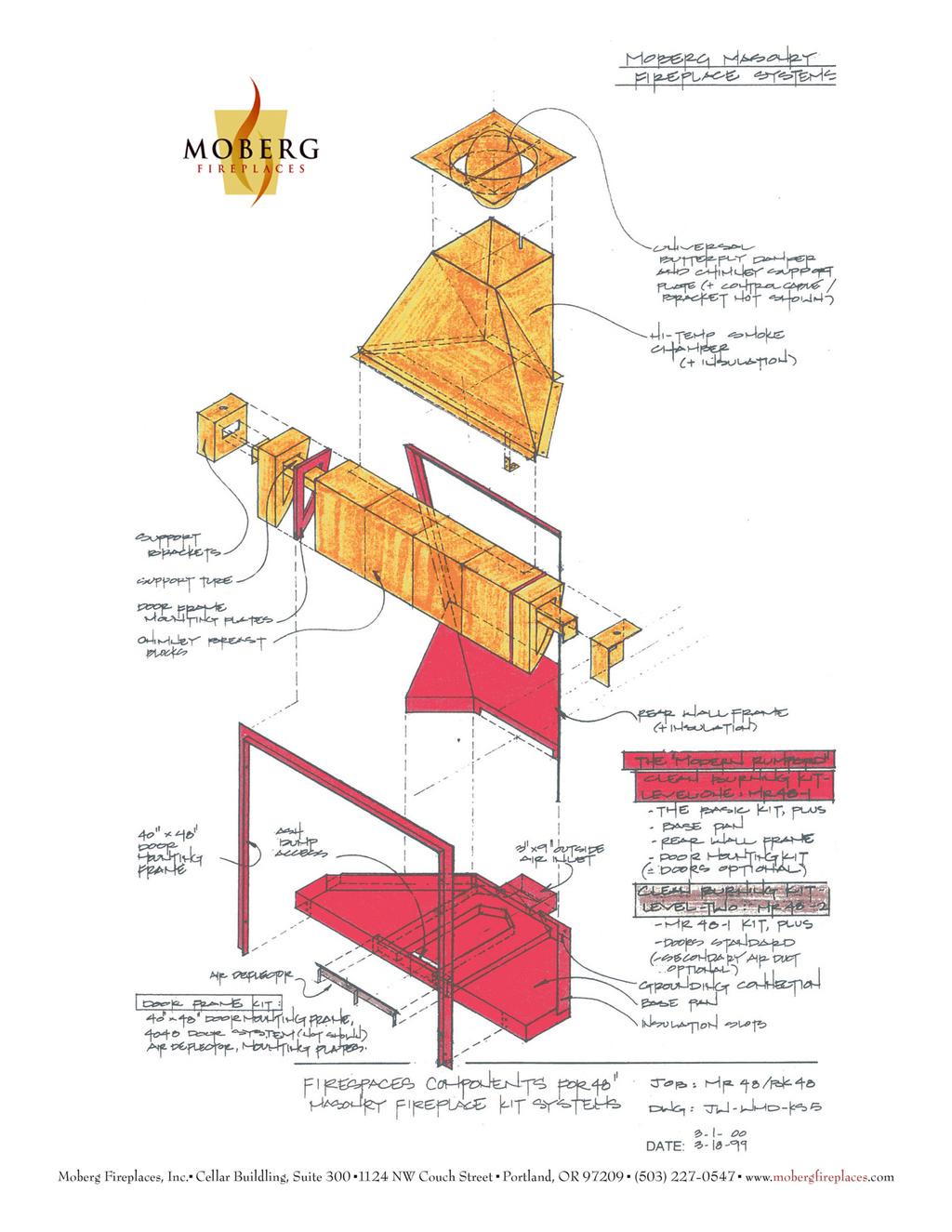
3 Cellar Building, Suite NW Couch Street Portland, OR Ph Fax MODERN RUMFORD FIREPLACE CONSTRUCTION GUIDELINES FOR MR-48-1 KIT SYSTEMS 7/06/05 FOUNDATION It is essential that the support for the Modern Rumford be designed to carry the weight of this masonry fireplace. The support will typically consist of one of the following: a concrete block foundation over which has been cast a six-inch thick reinforced concrete slab, a thickened slab-on-grade concrete floor, or an engineered floor structure designed to carry this type of load. Make sure that the sub-hearth area is a completely non-combustible base, unless the structure is also engineered and approved for combustible underlayments. See attached installation drawings Typical Code Minimum Construction at the end of the Typical Construction Details section for general assembled dimensions with code-minimum thicknesses. Actual thicknesses will vary depending on individual design characteristics. Assembled dimensions with nominal 6 wide CMU construction are shown in drawings Typical Complete Kit Construction, found at the end of the Typical Assembly Drawings section. Consult with your engineer or architect to project actual weights to be considered for structural support design. FIREPLACE ASSEMBLY In first attached section, Typical Assembly Drawings, see color exploded isometric drawing KS-5 for typical layout of Modern Rumford System s components. Within that drawing, layout of Clean-Burning Kits Level One is similar for the MR 48-1 system. In addition, Assembly Figures 1 to 16 show a step-by-step process for the entire fireplace assembly. FIREBOX FRAME AND MASONRY CASING Place the base pan in position (Figure 1) to determine the exact placement of the fireplace. Draw an outline of the base pan on the supporting surface and do your masonry casing layout. Modern Rumford fireplaces can be constructed in a masonry casing with virtually any geometric footprint as long as code minimum wall thicknesses are maintained. Refer to Figures 3-7 for typical block layout in a corner installation. If reinforcing is coming up from below, make sure to align the vertical bars with the block cores. If you are installing Foamglas cellular glass insulation underlayment (to prevent heat migration downward and possible cracking of slab or heat transferring into engineered/approved combustible underlayment), cut the Foamglas to
4 fit under basepan and install into position on the prepared surface. Make sure that the surface is flat and level so that the unit will end up level and plumb. Bolt the rear wall frame to base pan (Figure 2) and install over Foamglas or into position on foundation slab. Set and level base pan on a layer of mortar (or thin-set if leveling over insulation) to assure future alignment of door-mounting frame and chimney breast above. Note the circular openings in the back and side walls of the frame for gas connections. Those connections should be installed before firebrick is set. If you are planning for a gas connection, consult Moberg Fireplaces and obtain a copy of instructions of Gas Connections for Modern Rumford Fireplaces. Cover the pan to keep miscellaneous debris from accumulating in it and potentially damaging insulation over air ducts. Once the frame is in place, lay out the first course of block or other all-masonry casing (Figure 3). Unpack the 2 rigid K-Fac mineral fiber board insulation, that comes standard with each kit, and cut in place to fit (Figure 4) vertically along side and rear walls of rear wall frame. Place first course in the slots around the back and sides of the basepan. Continue placing boards up against the backside of the frame until the firebox is insulated to the top (Figure 5). Do not use K-Fac as an underlayment for the basepan or other masonry. Continue construction of masonry casing until either 8 high block is built up seven courses or other masonry is built up to an equivalent point. Make sure that where the lintel bracket will sit is 56-5/8 high (measured from the bottom surface of the basepan) on each side wall, or flush with the top of the rear wall frame (Figure 6). If the walls are to be reinforced and/or poured with concrete, they should be poured during this phase (Figure 7). CHIMNEY BREAST ASSEMBLY It is now time to prepare the chimney breast. (Alternatively, the assembly can be installed after the firebrick firebox is built. See Figure 12.) The left or right pieces with the door frame-mounting plates pre-installed are the first chimney breast pieces that you are going to mount. Slide one 3-3/4 breast block onto the steel lintel tube, making sure that the mounting plate is to the outside of the 48 firebox opening. Continue placing the remaining four 12 wide refractory breast blocks, and then the last plate and 3-3/4 block. Make sure that the door frame-mounting plates are fully hammered on and are positioned correctly (left on the outside left, right on the outside right as you face the firebox opening). Blocks may be sealed with high-temperature or refractory sealant, but joints must be minimized (maximum 1/64 ) to insure a correct placement along the lintel. Use the door-mounting frame to check correct placement. The holes in the top of the doormounting frame should align with the stud bolts of the plates (and occur directly above companion holes on front face of base pan when installed). If the fireplace will have doors (vs. screens), set the door and recheck for plumb (front to back as well as left to right) and square. Remove frame and mount later. On the outside of the 3 3/4 refractory breast blocks, mount the support brackets that will rest on the adjacent masonry casing sidewalls. Attach the eyebolts into the support brackets and insert the 3/4 lifting pipe into the eyebolts. This creates a temporary handle with which to lift the entire chimney breast assembly into position. This will be a heavy assemblage, so make sure enough people are available to raise and lift it into place carefully, particularly if the mortar under the masonry you will rest the brackets on is not fully set. Or, you can raise and set the assemblage with a motorized or mechanical lift. Now bolt the door-mounting frame to the basepan at the bottom and to the breast block/door frame mountingplates at the top. Check the door-mounting frame for plumb, level and square. Adjust the chimney breast placement if the frame is way out of alignment, and/or shim the frame with washers at mounting points if minor adjustment is all that is necessary. Once the breast is in place, and you have checked the (plumb and level) door-mounting frame for alignment, remove the pipe and eyebolts. FIREBOX CONSTRUCTION Now it is time to go back and build your firebrick firebox. Note: you do not have to do it in this order; you can build the firebrick firebox before you mount the chimney breast, but you must leave room for the chimney breast to fit in and confirm the fit before you build the firebox. Lay 1-1/2 Foamglas in the open cavities of the basepan to bring the base for the firebox hearth up to the level of the top of the inner air channels (or lay firebrick splits if insulated protection is not required for the sub-hearth base). Then, lay firebrick splits (Figure 8) for the firebox floor (inner hearth) and under the
5 area that will form the back and sidewalls. Now, you can lay the full-size bricks that form the back and side walls (Figure 9). Modern Rumford fireboxes can be built either with firebrick laid flat, normally at 4 to 4-1/2 thick, or on edge. If laid on edge, make sure that walls are at least 2 thick and that when combined with the casing masonry, they satisfy the minimum requirements of the local code, as well as the architectural requirements of the project. Follow the angles set up by the back frame, cutting the firebrick to overlap and/or fill the corners. Because the back wall is on an 8-1/2º slope, firebrick must be tipped forward from the very first course. Since the rear wall will be laid on an angle and the sidewalls laid level, they won t bond through. Typically, the rear wall should run behind the sidewalls. However, when sawn-face firebricks are used (soapstone for example), they can have the 8-1/2º slope built into the face and can be laid level and also can be bonded through. Build the firebox up to the top of the rear wall frame on the back wall and on the side walls (Figure 10). You will need to cut the brick around the breast blocks (Figure 11), or if you decide to install the firebox before the chimney breast, wait and do the last few courses with breast blocks in place. Make sure at the top of the back wall you have at least 5 between the back wall and the top of the breast blocks for the throat of this fireplace (Figure 12). SMOKE CHAMBER AND DAMPER CONSTRUCTION Lift the large metal smoke chamber liner into position and align the 1 flange just behind the breast block ledge. This is also a heavy component, so make sure enough people are available to lift into place, or a mechanical lift is available. The front face of the smoke chamber should line up with the interior edge of the breast block (Figure 13), and the front flange should rest on the breast block assembly. The rear flange should rest on the masonry casing/rear wall of the fireplace. Cut the K-Fac insulation to fit the outer side and back surfaces only of the smoke chamber and adhere it to the metal surface with high-temperature silicone or refractory cement. The front face should already have a thin ceramic fiber blanket pre-installed. Then, build a solid masonry casing around the metal smoke chamber, also setting on the casing around the firebox, until you reach within 3/8 of the top of the smoke chamber. This casing should be constructed similar to the casing built below, using CMU, brick masonry or concrete masonry, as allowed by code, and in the thickness necessary for both code and minimum structural requirements. For example, if an all-masonry chimney will be placed above the smoke chamber, the casing must be corbelled, reinforced with angle iron, or otherwise built to transfer the weight to the firebox casing below. Consult your architect or engineer for the design of structural masonry casings. The smoke chamber casing must also rise adjacent to the insulation and corbel or taper so that it will physically support the flat frame plate of the damper assembly, at least at the front and back edges of the plate. At this point you are level with the top of the smoke chamber. If reinforcing is required, you should then do your final concrete pour to reinforce your block work and prepare for supporting the chimney. Make sure that neither masonry casing nor concrete pour rise above the level of the metal smoke chamber, and create a flat and level surface for supporting the heavy frame of the damper assembly. Also, ensure that all insulation is encased in masonry and/or covered with mortar or concrete (at least 3/8 thick), or will be covered by damper frame plate. Then install the chimney damper and frame plate assembly (Figure 14). This assembly must be lowered into the smoke chamber so that the guide pin (at the rear of the circular ring which supports the damper blade) slides down the slot at the rear of the smoke chamber. Make sure the assembly goes down until the flat frame of the damper assembly rests both on the metal smoke chamber itself, and on the masonry casing. Four holes in the frame can be used to lag-bolt the assembly into the masonry, if desired, for securing the assembly in position. Make sure that the stainless damper cable is hanging down into the smoke chamber, and is accessible for connecting to stop bracket and handle later on (see damper handle and grating). CHIMNEY AND OUTSIDE AIR The MR-48 systems require 14 round (I.D.) UL-listed, insulated metal flues, or masonry flue liners that are typically slightly larger. If you are going to construct the chimney in masonry, you should then set your first 16 x 16 square (O.D.) flue liner (minimum 14 x 14 I.D.) or 15 round (I.D.) flue liner and continue with your masonry chimney. Or, if you are going to install a UL-listed insulated metal chimney, then you should set and secure your factory-built anchor plate which makes the transition from the smoke chamber to the metal chimney system. Follow the chimney manufacturer s instructions for mounting the plate and ensure that no portion of the anchor plate or chimney system interferes with damper blade before proceeding further. Then proceed with the assembly of your chimney. We recommend a minimum of 15 feet of actual flue for good operations.
6 At the rear of the fireplace, there is a 3 x 9 inlet that connects to the air channels inside the base pan. From this opening, connect a minimum 6 round or 4 square transfer duct to an exterior screened intake located at or below firebox level. You can utilize the optional outside air adapter available from Moberg Fireplaces, which allows for optional connections in four directions, or you can customize a non-combustible connection, using metal or masonry transfer ducting which meets the minimum requirements of the local code. Make sure the intake screening does not restrict the opening to less than 16 in. 2 net free area. If the total length of the intake connection will exceed 15 feet and/or require more than two 90º offsets, it may be necessary to increase the size of the transfer ducting, to assure proper minimum air flow. Consult your architect or engineer for the design of circuitous intake ducts and/or contact Moberg Fireplaces for more information. To prevent the unwanted infiltration of cold outside air, you can install a damper in-line of the transfer duct and/or purchase the optional air outlet cover from Moberg Fireplaces. Not all installations will require outside air connections for meeting minimum code requirements, but the connection of the outside air duct is important for assuring the clean-burning and smoke-free operation of Modern Rumfords in most applications. However, the location of the intake at the exterior of the fireplace must not be placed where it could ingest flammable gases or liquids, or conversely where propane from a loglighter or gas log set could expel gas into a flammable environment, or in exterior locations that are subjected to negative pressures during adverse wind conditions. MAKE-UP AIR PROVISIONING In planning for the installation of a Modern Rumford, as with all open fireplaces, it is necessary to provide make-up air for combustion and proper operation. This is an addition to combustion air, as it represents unrestricted air that must cross the opening and be exhausted up the flue. Although make-up air is effectively a necessary heat loss in all open fireplaces, the MR 48 operates without spillage utilizing less room air than most open fireplaces. For wood burning applications, we recommend providing make-up air through the building s mechanical air handling system adequate to allow up to 500 cfm for fireplace opening, with the following exceptions: For fireplace installations using 6 round outside combustion air system built into the hearth, makeup air can be reduced by 20%, to 400 cfm. For fireplace installation with gas log sets having outputs less than 100,000 BTU/hr, makeup air can be reduced by 50%, to 250 cfm. However, mechanical system capacity must be sized for larger volumes, if future wood burning operations are possible. In the room containing the fireplace, make-up air must either be 1) continuously supplied by an air-handling system, specifically for the fireplace, or 2) be available through activation of a switch or other control mechanism before the fireplace is operated. If make-up air is also a proposed substitute for code-required combustion air ducting, the use of this air supply must be coordinated with all fireplace operations, and be acceptable to the jurisdiction having authority as providing an equivalent standard. We recommend that the mechanical contractor furnish all hardware and size the installation components properly prior to fabrication and installation of the mechanical air handling system in the room containing the fireplace. Due to the possibility of a power failure during fireplace operations, it is necessary to ensure the optional availability of make-up air in the room containing the fireplace, from openable windows and/or doors of equivalent cross-sectional area as the fireplace opening. FINISHED FACING Now the fireplace is ready for its finished facing. Detail as in architects or designers plans and per minimum code requirements. See attached section Typical Installation Details for samples of finished solutions. The Modern Rumford does not provide any limitations to finish design beyond the minimum dimensional specifications shown here, or the specific internal geometries defined by the kit construction. If doors or screens are going to be mounted to the doormounting frame, be sure that finished facing/surround does not impinge on the minimum 48 wide and 40 high opening created by the door-mounting frame.
7 DAMPER HANDLE Clean-Burning Level One Modern Rumford Kits utilize the unique Moberg Fireplace Single-Stage Dampering Mechanisms. (Standard manual cable-activated or optional motorized actuators are available). Before they can be properly operated, the standard stainless damper cable and handle assembly and the stop bracket must be installed and fitted. Unless they are factory pre-installed, follow these instructions for assembly: Attach stop bracket to threaded studs found on right hand base of smoke chamber with key-hole end down, and bolt into place with stop bracket keyhole flange toward the inside of the smoke chamber. (See Single-Stage Damper Operations illustration at the end of assembly figures). Pull hanging cable down from the damper blade through the throat of firebox and then pull the separate cable end of the handle assembly up through keyhole in the stop bracket. Pull down on the damper cable until damper blade hits the stopping flange and is in closed position. Attach the handle assembly cable to the damper cable by threading the damper cable into the lock-joint connector, then pull up on the handle assembly cable until the lock-joint connector is in position just below the keyhole flange. Tighten the lock-joint connector so assembly can be tested for open and closed position. Adjust, if necessary, for easy release. The damper is manipulated by pulling the cable and stop connector out of the keyhole slot and letting the counterweight action of the damper release the cable up (open) or by pulling down to align the cable and stop connector in the closed position. See Modern Rumford Level One Fireplace Operating Instructions for further details. NOTICE The Modern Rumford Fireplace Kit is a guidance system for constructing a clean-burning, code-compliant all-masonry fireplace. As a masonry fireplace, it must adhere to local fireplace code. THIS KIT DOES NOT IN ANY WAY REPLACE THE MINIMUM CODE REQUIREMENTS FOR MASONRY FIREPLACES. It is the intention of the manufacturer that the Modern Rumford Level 1 Kit be installed and assembled according to the following Construction Guidelines, as well. All aspects, including finishing treatments and clearances to combustibles, chimneys, etc., must also conform to local codes for standard masonry fireplaces. If you have any questions or doubts about what is allowable in your area, consult your local building code requirements for masonry fireplaces before proceeding with the installation of your Modern Rumford Kit.
8
9 Modern Rumford MR 48 fireplaces TYPICAL ASSEMBLY DRAWINGS
10
11
12
13 Modern Rumford MR 48 fireplaces PHOTOS OF TYPICAL ASSEMBLY
14


.")
15 Concrete supports at floor level plus courses for raised hearth. Mortar bed to set basepan (shown at rear). Basepan set and leveled.


16 Attaching backwall form frame Backwall attached and ready for firebrick.


17 Air intake adapter shown at rear. Gas line attached.


18 4 block at rear for shallow installation. Board insulation applied to rear and sidewall.


19 Block surround to 3 rd course. Block to course 7 (56 5/8 )


20 Insulation and block to top of firebox (course 7). Shoulder bracket, lifting eye, breast block, lintel bar and refractory mortar. Breast block and lintel bar ready to be lifted into place.


21 Breast block assembly being set into place. Attaching Door frame.


22 Breast block assembly in place with lifting rod still in place. Door open frame attached. Smoke shelf.


23 Smoke chamber in place. Masonry surround for the smokechamber.


24 Setting damper on smoke fireplace capping slab. Finished blockwork ready for firebrick, veneer and chimney.
25 Modern Rumford MR 48 fireplaces Typical Construction Details
CHIMNEYS AND FIREPLACES
 CHAPTER 10 CHIMNEYS AND FIREPLACES SECTION R1001 MASONRY FIREPLACES R1001.1 General. Masonry fireplaces shall be constructed in accordance with this section and the applicable provisions of Chapters 3
CHIMNEYS AND FIREPLACES
 SECTION R1001 MASONRY FIREPLACES R1001.1 General. Masonry fireplaces shall be constructed in accordance with this section and the applicable provisions of Chapters 3 and 4. R1001.2 Footings and foundations.
Instructions for Finishing Heater
 RR 5 Shawville Québec J0X 2Y0 Voice 819.647.5092 Fax 819.647.6082 mheat@mha-net.org www.heatkit.com Revised March 8, 2008 Instructions for Finishing Heater Table of Contents General...1 Installing the
Contraflow Heater Core 22 firebox with replaceable liner Front White Bake Oven
 Revised, July 10, 2008 Contraflow Heater Core 22 firebox with replaceable liner Front White Bake Oven Assembly Drawings Material List for core...2 Masonry:...2 Hardware:...2 Hardware sources:...2 Setting
Heat-Kit System Modular Contraflow Masonry Heater Core Assembly Manual
 Revised January 11, 2011 Heat-Kit System Modular Contraflow Masonry Heater Core Assembly Manual HK-22no 22 Firebox RR 5 Shawville Québec J0X 2Y0 Voice 819.647.5092 Fax 819.647.6082 email mheat@heatkit.com
FIREPLACE INSERT ENCLOSURE INSTALLATION INSTRUCTIONS
 FIREPLACE INSERT ENCLOSURE INSTALLATION INSTRUCTIONS ENCLOSURE MODEL 90566400 FOR INSERT MODEL 5660NA And ENCLOSURE MODEL 90566000 FOR INSERT MODEL 5660 STANDARD KEEP THESE INSTRUCTIONS FOR FUTURE USE
DIVISION: SPECIALTIES SECTION: MANUFACTURED FIREPLACES REPORT HOLDER: FIRE ROCK PRODUCTS LLC
 0 Most Widely Accepted and Trusted ICC ES Evaluation Report ICC ES 000 (800) 423 6587 (562) 699 0543 www.icc es.org ESR 2599 Reissued 04/2018 This report is subject to renewal 04/2020. DIVISION: 10 00
Summit Stone. Summit Stone. Summit Stone. Standard Outdoor Fireplace Installation Guidelines. Summit Stone Standard Outdoor Fireplace
 1 2 www. w.co coun tymateri rials. s.co m Summit Stone Standard Outdoor Fireplace Installation Guidelines Standard Outdoor Fireplace Installation Guidelines Concrete Pad Preparation Before beginning any
INSTALLATION GUIDE PLEASE READ ENTIRE INSTRUCTION MANUAL BEFORE PROCEEDING!
 DURA - TRENCH INSTALLATION GUIDE This guide is intended to aide in the installation of Dura-Trench systems. There are many different applications and situations for the use of this product and the installation
DETAIL INSTRUCTION No. 1
 BEFORE BEGINNING INSTALLATION, PLEASE READ THROUGH ALL INSTRUCTIONS. Uncrate shipment and check against packing list to insure all materials are included before beginning installation. If any discrepencies
Heat-Kit System Modular Contraflow Masonry Heater Core
 Heat-Kit System Modular Contraflow Masonry Heater Core Assembly Manual HK-22fo 22 Firebox with Front or Rear Bake Oven AUTHOR NAME Updated on Masonry Stove Builders 25 Brouse Rd., RR 5 Shawville, Quebec
INSTALLING A POUR-IN-PLACE DOCK LEVELER (EH & RR)
") INSTALLING A POUR-IN-PLACE DOCK LEVELER (EH & RR) Part A: Prepare the Site & Make the Floor 1.) Prepare (concrete) dock wall and pit floor as shown in the diagrams. Pit floor should taper from back to
INSTALLING A POUR-IN-PLACE DOCK LEVELER (EH & RR) Part A: Prepare the Site & Make the Floor 1.) Prepare (concrete) dock wall and pit floor as shown in the diagrams. Pit floor should taper from back to
CONSTRUCTION SPECIFICATION FOR THE INSTALLATION OF ELECTRICAL CHAMBER
 ONTARIO PROVINCIAL STANDARD SPECIFICATION METRIC OPSS 602 MARCH 1993 CONSTRUCTION SPECIFICATION FOR THE INSTALLATION OF ELECTRICAL CHAMBER 602.01 SCOPE 602.02 REFERENCES 602.05 MATERIALS TABLE OF CONTENTS
Installation Instructions
 Installation Instructions SAVE THESE INSTRUCTIONS Please read this entire manual before you install and use your room heater. Failure to follow instructions may result in property damage, bodily injury,
1. Start by removing the ash-pit door. Remove from frame by removing two rivet pins. Remove the frame by unscrewing the 4 bolts. (Fig 1.
 Page 1 INTRODUCTION This instruction shows how to replace ceramic bricks in the Solo Plus and Excel solid fuel boiler. Please read carefully before replacement. Follow the instruction point by point. Fig
Multi-Piece Shower with Trench Drain
 INSTALLATION INSTRUCTIONS Multi-Piece Shower with Trench Drain (For models requiring cut-out in floor) 1062 This packet includes installation instructions for the Bestbath products shown below. (These
RECOMMENDED STANDARDS for the INSTALLATION of WOODBURNING STOVES
 RECOMMENDED STANDARDS for the INSTALLATION of WOODBURNING STOVES Prepared By Office of State Fire Marshal Maine Office of Energy Resources 52 State House Station 55 Capital Street Augusta, ME 04333 Augusta,
Multi-Piece Shower with Trench Drain
 INSTALLATION INSTRUCTIONS Multi-Piece Shower with Trench Drain (For models with standard pan) 105 This packet includes installation instructions for the Bestbath products shown below. (These instructions
The Ashland Project. Total Area: 1,778 Sq.Ft. 3 Bedroom, 2 Bath, 2 Car Garage
 The Ashland Project Total Area: 1,778 Sq.Ft. 3 Bedroom, 2 Bath, 2 Car Garage The garage and bedroom extend from the front of this three bedroom home, drawing you visually into the entryway. Brick and stucco
APPLICATION AND LISTING
 DURALINER (SDL) 6"-8" DIAMETER (ROUND & OVAL) INSTALLATION INSTRUCTIONS MH14420 CMH1329 THESE INSTALLATION AND OPERATION INSTRUCTIONS COVER DURALINER MASONRY RELINING SYSTEM A MAJOR CAUSE OF CHIMNEY RELATED
Multi-Piece Shower with Trench Drain
 INSTALLATION INSTRUCTIONS Multi-Piece Shower with Trench Drain (For models requiring mud set) 1069 This packet includes installation instructions for the Bestbath products shown below. (These instructions
PORTRAIT WARNING HOT GLASS WILL CAUSE BURNS. DO NOT TOUCH GLASS UNTIL COOLED. NEVER ALLOW CHILDREN TO TOUCH GLASS. 569 Ledge Front
 PORTRAIT 569 Ledge Front CSA approved for use with Valor Models 530I Heaters ONLY INSTALLATION INSTRUCTIONS! WARNING HOT GLASS WILL CAUSE BURNS. DO NOT TOUCH GLASS UNTIL COOLED. NEVER ALLOW CHILDREN TO
Heat-Kit System Modular Contraflow Masonry Heater Core Assembly Manual
 Revised September 7, 2000 Heat-Kit System Modular Contraflow Masonry Heater Core Assembly Manual HK-22no 22 Firebox, no bakeoven Custom: top left exit, reduced height, clearance for beam on right RR 5
How to construct The Rittman fireplace.
 How to construct The Rittman fireplace. Use only the UL-approved Firerock from Unilock. Review and check all components Dry-lay components and plan assembly. Front view of assembled firebox. Main unit
EO-RB1500 RUMFORD 1500B Refractory Cement Brick Kit
 EO-RB1500 RUMFORD 1500B Refractory Cement Brick Kit The Refractory Cement Brick Kit allows you to line your RUMFORD 1500B fireplace with refractory bricks. Before you begin the installation, please take
Summit Stone. Summit Stone. Summit Stone Corner Outdoor Fireplace. Installation Guidelines. Summit Stone. Corner Outdoor Fireplace
 1 2 www.countymaterials.com Summit Stone Tumbled Landscape Units Summit Stone Corner Outdoor Fireplace Installation Guidelines 2015 County Materials Corporation Summit Stone Tumbled Landscape Units Summit
Tek Spec 4.0. Reference Guide
 Tek Spec 4.0 Reference Guide RECOMMENDED PRACTICES FOR FIREPLACE, CHIMNEY AND BAKE OVEN CONSTRUCTION A well-constructed masonry fireplace or bake oven adds several elements of interest to the home, providing
BioPrism Solid Surface
 Please read all instructions before installing products. STORAGE & HANDLING: Check for damage that may have occurred during transit. Keep receptor flat on pallet, as it was shipped, until ready to install.
DIVISION: SPECIALTIES SECTION: MANUFACTURED FIREPLACES REPORT HOLDER: MASONRY FIREPLACE INDUSTRIES, LLC
 0 Most Widely Accepted and Trusted ICC ES Evaluation Report ICC ES 000 (800) 423 6587 (562) 699 0543 www.icc es.org ESR 2401 Reissued 01/2018 This report is subject to renewal 01/2019. DIVISION: 10 00
BioPrism Solid Surface
 Please read all instructions before installing products. STORAGE & HANDLING: Check for damage that may have occurred during transit. Keep receptor flat on pallet, as it was shipped, until ready to install.
Isokern MAGNUM Fireplace and DM Chimney System
 Isokern MAGNUM Fireplace and DM Chimney System Installation, Operation, Maintenance and Owner s Manual Isokern MAGNUM Models 82060 & 82072 A PRODUCT OF EARTHCORE INDUSTRIES, LLC Important: This manual
PLEASE READ ENTIRE INSTRUCTION MANUAL BEFORE PROCEEDING!
 INSTALLATION GUIDE This guide is intended to aide in the installation of Dura-Trench systems. There are many different applications and situations for the use of this product and the installation procedures
Recent Project by William Davenport, Turtlerock Masonry Heat
 Recent Project by William Davenport, Turtlerock Masonry Heat Location: Morrisville, VT Project: Smaller contraflow retrofit into renovated and re-insulated VT cape farmhouse. Background: Over the last
Standard Installation Fire Damper Models: 119, 119(F), 119(SS), D19
, 119(SS), D19") Standard Installation Fire Damper Models: 119, 119(F), 119(SS), D19 Page 1 or 8 APPLICATION This fi re damper is intended to restrict the passage of fl ame. The standard installation requires that the
Standard Installation Fire Damper Models: 119, 119(F), 119(SS), D19 Page 1 or 8 APPLICATION This fi re damper is intended to restrict the passage of fl ame. The standard installation requires that the
A. ASTM C190 - Test Method for Tensile Strength of Hydraulic Cement Mortars
 SECTION 04850 (04 40 00) MSI PRECAST STONE VENEER SYSTEM PART 1 GENERAL 1.1 SECTION INCLUDES A. MSI Precast Stone Veneer for exterior and interior vertical surfaces. 1.2 RELATED SECTIONS Specifier Notes:
C.R. LAURENCE CO., INC. Intelli-Track SPS. Phase One - Installation Instructions
 Tools and Supplies: C.R. LAURENCE CO., INC. Intelli-Track SPS Phase One - Installation Instructions Ratchet Wrench with 4" Extension 9/16" Open-End Wrench (two required for suspension mounting) 9/16" Hex
Isokern MAGNUM Fireplace
 Isokern MAGNUM Fireplace with Fire-Lite Application and DM Chimney System Installation, Operation, Maintenance and Owner s Manual MAGNUM Models 28, 36, 42, 48, 60 & 72 A PRODUCT OF EARTHCORE INDUSTRIES,
Design No. HI/BP PERIMETER FIRE BARRIER SYSTEM Hilti, Inc. ASTM E 2307 Table 1
 FIRESTOP JOINT SPRAY CFS-SP WB SILICONE JOINT SPRAY CFS-SP SIL F-RATING 2-HR. 2-HR. T-RATING -HR. -HR. APPLICATION THICKNESS PERIMETER FIRE BARRIER SYSTEM Hilti, Inc. ASTM E 2307 Table /8" WET FILM (/6"
CF-2100 SERIES FIREPLACES
 The Ultimate in Radiant Heating Systems CF-2100 SERIES FIREPLACES INSTALLATION MANUAL October, 2005 Crossfire Fireplaces 249 Bridge Street West, P.O. Box 121 Campbellford, Ontario, Canada K0L 1L0 Tel:
Linear Drainage ZF806 ZF812
 Linear Drainage ZF806 ZF812 Fiberglass Trench Installation Instructions ZF806 Accessories 6" [152mm] Wide Fiberglass Trench Drain System Below are some of the ZF806 trench drain components typical to an
CONSTRUCTION SPECIFICATION FOR INSTALLATION OF ELECTRICAL CHAMBERS
 ONTARIO PROVINCIAL STANDARD SPECIFICATION OPSS.PROV 602 NOVEMBER 2017 CONSTRUCTION SPECIFICATION FOR INSTALLATION OF ELECTRICAL CHAMBERS TABLE OF CONTENTS 602.01 SCOPE 602.02 REFERENCES 602.03 DEFINITIONS
De Montfort Mark 7 Incinerator (Flatpack)
") De Montfort Mark 7 Incinerator (Flatpack) Introduction This design is specially for those occasions when a large number of incinerators are to be built at one location and transported to the places where
De Montfort Mark 7 Incinerator (Flatpack) Introduction This design is specially for those occasions when a large number of incinerators are to be built at one location and transported to the places where
Isokern STANDARD Fireplace
 Isokern STANDARD Fireplace with Fire-Lite Application and DM Chimney System Installation, Operation, Maintenance and Owner s Manual STANDARD Models 36, 42 & 46 A PRODUCT OF EARTHCORE INDUSTRIES, LLC. Important:
WARNING!! TO ENSURE THE SAFE AND EFFICIENT OPERATION OF THIS HEATER, SECTION 5 MUST BE REVIEWED PRIOR TO STARTING THE INSTALLATION
 INSTALLATION MANUAL READ THIS ENTIRE MANUAL INCLUDING THE WARRANTY SECTION BEFORE STARTING THE INSTALLATION WARNING!! TO ENSURE THE SAFE AND EFFICIENT OPERATION OF THIS HEATER, SECTION 5 MUST BE REVIEWED
with Fire-Lite Application
 Isokern MAGNUM Fireplace with Fire-Lite Application and DM Chimney System Installation, Operation, Maintenance and Owner s Manual MAGNUM Models 82028, 82036, 82042 & 82048 A PRODUCT OF EARTHCORE INDUSTRIES,
SECTION (Master Template Final-05) ELECTRICAL BOXES. A. Provide boxes for electrical equipment and wiring devices as follows:
 ELECTRICAL BOXES. A. Provide boxes for electrical equipment and wiring devices as follows:") SECTION 16130 (Master Template Final-05) ELECTRICAL BOXES PART 1 GENERAL 1.01 SECTION INCLUDES A. Provide boxes for electrical equipment and wiring devices as follows: 1. Wall and ceiling outlet boxes.
SECTION 16130 (Master Template Final-05) ELECTRICAL BOXES PART 1 GENERAL 1.01 SECTION INCLUDES A. Provide boxes for electrical equipment and wiring devices as follows: 1. Wall and ceiling outlet boxes.
SECTION LAGUNA SERIES TOP HUNG SLIDING DOOR SYSTEM
 Page 1 of 6 SECTION 08 32 20 LAGUNA SERIES TOP HUNG SLIDING DOOR SYSTEM USE THIS SECTION WHEN SPECIFYING OVERHEAD SUPPORTED GLASS SLIDING DOORS. SECTION INCLUDES OVERHEAD SLIDING TUBE ASSEMBLY, MOUNTING
SECTION TILT-UP PRECAST CONCRETE SANDWICH PANELS. A. Work includes, but is not limited to, the following:
 PART 1 GENERAL 1.01 SUMMARY SECTION 03460 TILT-UP PRECAST CONCRETE SANDWICH PANELS A. Work includes, but is not limited to, the following: 1. Architectural precast concrete sandwich wall panels. 2. Integral
Claremont Fireplace Kit
 Claremont Fireplace Kit INSTALLATION INSTRUCTIONS! 1 Planning Familiarize yourself with all applicable local building codes. Only install the fireplace in a location and in such a way as to meet all relevant
P36-10 / P36E-10 Gas Fireplace. 11 W.C. (2.74 kpa) 10 W.C. (2.49 kpa) 6.4 W.C. (1.59 kpa) 22,000 BTU/h (6.44 kw) 28,500 BTU/h (8.
 10 W.C. (2.49 kpa) 6.4 W.C. (1.59 kpa) 22,000 BTU/h (6.44 kw) 28,500 BTU/h (8.") Model P36-NG10 P36-LP10 P36E-NG10 P36E-LP10 Fuel Type Natural Gas Propane Natural Gas Propane Gas Fireplaces P36-10 / P36E-10 Gas Fireplace Minimum Supply Pressure 5 W.C. (1.25 kpa) 12 W.C. (3.00 kpa)
Model P36-NG10 P36-LP10 P36E-NG10 P36E-LP10 Fuel Type Natural Gas Propane Natural Gas Propane Gas Fireplaces P36-10 / P36E-10 Gas Fireplace Minimum Supply Pressure 5 W.C. (1.25 kpa) 12 W.C. (3.00 kpa)
Outer Skin Kit & Flue: IB600, IB850, IB1100 Installation Manual
 Outer Skin Kit & Flue: IB600, IB850, IB1100 Installation Manual Please see IB series product installation guide for details of installing the gas fire into this preformed metal cavity. Important: The appliance
NORTH HARRIS COUNTY REGIONAL WATER AUTHORITY PIPE HANGERS, Section PIPE HANGERS, SUPPORTS, AND RESTRAINTS
 PART 1 GENERAL 1.01 SUMMARY Section 15140 PIPE HANGERS, This Section includes the furnishing and subsequent installation of: A. Pipe and equipment hangers, supports, and associated anchors B. Equipment
F500 Steeplechase Waterjump with Valve Option
 Gill Athletics www.gillathletics.com Phone: (800) 367-3090 Fax: (217) 367-8440 Excavation F500 Steeplechase Waterjump with Valve Option Installation Guide Read all instructions before installing!!! Establish
SECTION HANGERS AND SUPPORTS FOR PLUMBING
 SECTION 22 05 29 HANGERS AND SUPPORTS FOR PLUMBING PART 1 - GENERAL 1.1 RELATED DOCUMENTS A. Drawings and general provisions of the Contract, including General and Supplementary Conditions and Division
STRUCTURAL STEEL FRAMING
 SECTION 05 12 00 - STRUCTURAL STEEL FRAMING PART 1 - GENERAL 1.1 SUMMARY A. Section includes 1. Structural steel framing 2. Structural steel framing required for support and framing of rooftop mechanical
Modular Masonry Fireplace Installation Instructions Models TFS/OFS* 33 /39 /44 /49 /63
 WWW.BURNTECH.COM Modular Masonry Fireplace Installation Instructions Models TFS/OFS* 33 /39 /44 /49 /63 THIS ENTIRE INSTALLATION GUIDE IS TO BE FOLLOWED IN ITS ENTIRETY FOR INDOOR TRADITIONAL FIREPLACE
Genesis Panel Systems LLC Dura-Max Brick Panel Siding Installation Instructions
 Genesis Panel Systems LLC Dura-Max Brick Panel Siding Installation Instructions Thank you for purchasing the Genesis Dura-Max Brick Panel system for your project. The system allows you to have the look
SECTION COMMON WORK RESULTS FOR FIRE SUPPRESSION
 Page 210500-1 SECTION 210500 - PART 1 - GENERAL 1.1 RELATED DOCUMENTS A. Drawings and general provisions of the Contract, including General and Supplementary Conditions and Division 01 Specification Sections,
TILT-UP PRECAST CONCRETE SANDWICH PANELS. A. Work includes, but is not limited to, the following:
 PART 1 GENERAL 1.01 SUMMARY SECTION 03460 TILT-UP PRECAST CONCRETE SANDWICH PANELS A. Work includes, but is not limited to, the following: 1. Architectural precast concrete sandwich wall panels. 2. Integral
SYSTEM 600 BILL CHANGER INSTALLATION INSTRUCTIONS Congratulations...
 www.standardchange.com 1-800-968-6955 Technical Phone Support is from 8:00AM to 7:30PM E.S.T., Monday-Friday Walk-in Service is from 8:00AM to 4:30PM E.S.T., Monday-Friday Parts Department is from 8:00AM
Masonry Firebox. Models MFP-33/39/44/49/63 THIS WOOD-BURNING FIREPLACE COMPLIES WITH UL127 STANDARD AS A FACTORY-BUILT APPLIANCE.
 Instructions Masonry Firebox Models MFP-33/39/44/49/63 THIS WOOD-BURNING FIREPLACE COMPLIES WITH UL127 STANDARD AS A FACTORY-BUILT APPLIANCE.! WARNING: THIS FIREPLACE IS APPROVED FOR USE AS A WOOD BURNING
SECTION EMBEDDED CMU/SPLIT FACE ARCHITECTURAL PRECAST/SITECAST CONCRETE. A. Site Cast or Tilt-Up CMU/Split Face Concrete Panels.
 SECTION 03460 EMBEDDED CMU/SPLIT FACE ARCHITECTURAL PRECAST/SITECAST CONCRETE PART 1 GENERAL 1.1 SECTION INCLUDES A. Site Cast or Tilt-Up CMU/Split Face Concrete Panels. B. Shop/Plant Cast CMU/Split Face
The fireplace, rekindled.
 The fireplace, rekindled. Precision-Engineered Masonry Fireplaces FireRock offers a simple way to build a high-end, all-masonry fireplace and chimney. This smartly designed system installs in a matter
DIVISION: SPECIALTIES SECTION: MANUFACTURED FIREPLACES REPORT HOLDER: EARTHCORE INDUSTRIES, LLC
 0 Most Widely Accepted and Trusted ICC ES Evaluation Report ICC ES 000 (800) 423 6587 (562) 699 0543 www.icc es.org ESR 2316 Reissued 10/2017 This report is subject to renewal 10/2018. DIVISION: 10 00
Rediflow Concrete Gas Flue System
 Rediflow Concrete Gas Flue System Rediflow Concrete Gas Flue System Rediflow the complete gas flue block system Red Bank s range of Rediflow pre-cast concrete gas flue block system manufactured to BS EN
GENERAL MECHANICAL SYSTEM REQUIREMENTS
 CHAPTER 13 GENERAL MECHANICAL SYSTEM REQUIREMENTS SECTION M1301 GENERAL M1301.1 Scope. The provisionsof thischapter shall governthe installation of mechanical systems not specifically covered in other
Nortrax Section David Manchester Road, Ottawa NON-STRUCTURAL METAL FRAMING 16 May 2014 Page 1
 16 May 2014 Page 1 PART 1 GENERAL 1.1 DESCRIPTION This section specifies steel studs wall systems, shaft wall systems, ceiling or soffit suspended or furred framing, wall furring, fasteners, and accessories
INSTALLING WATER-RESISTIVE BARRIERS & FLASHING
 INSTALLING WATER-RESISTIVE BARRIERS & FLASHING IN A TWO-LAYER STUCCO APPLICATION Fortifiber Building Systems Group provides this guide to assist installers by demonstrating a two-layer installation of
2002 Advanced Building Products, Inc., P.O. Box 98, Springvale, Maine TEL: ; FAX: ; WEBSITE:
 SECTION 07651 FLEXIBLE COPPER SHEET FLASHINGS Advanced Building Products, Inc. manufacturer many types of flexible copper sheet flashings. Due to their ductility, high tensile strength, and resistance
FreeStyle Linear Drain with Full Mortar Bed Adapter Kit
 FreeStyle Linear Drain with Full Mortar Bed Adapter Kit U.S. Patent No. 8,474,068 Patents Pending: Canada & EP Publication No. 2354339 Discard Linear Drain installation instructions and refer to these
Installation Instructions
 EconoDrain Trench Forming System Installation Instructions MultiDrain We Drain Your Site, Not Your Budget MultiDrain Systems, Inc. P.O. Box 88, Barium Springs, NC 28010 (704) 508-1010 or Toll Free 800-433-1119
ROOF MOUNT KIT OWNERS MANUAL
 ROOF MOUNT KIT OWNERS MANUAL Made in the USA by: Southwest Windpower, Inc. 1801 W. Route 66 Flagstaff, Arizona 86001 Phone: (928) 779-9463 Fax: (928) 779-1485 E-mail: info@windenergy.com Web: www.windenergy.com
Gas Fireplaces. P36D-10 Gas Fireplace. Unit Dimensions With Vignette Faceplate. *** Important: Framing height requires consideration of the hearth
 28-15/16 (735mm) Model P36D-NG10 P36D-LP10 Fuel Type Natural Gas Propane Gas Fireplaces Minimum Supply Pressure Manifold Pressure - High Manifold Pressure - Low 5 W.C. (1.25 kpa) 3.8 W.C. (0.95 kpa) 1.1
with Fire-Lite Application
 Isokern STANDARD Fireplace with Fire-Lite Application and DM Chimney System Installation, Operation, Maintenance and Owner s Manual STANDARD Models 80S36, 80S42 & 80S46 A PRODUCT OF EARTHCORE INDUSTRIES,
SECTIONAL OVERHEAD DOORS SECTION SECTIONAL OVERHEAD DOORS PART 1 GENERAL
 13686.00 SECTIONAL OVERHEAD DOORS 083613-1 1.1 RELATED DOCUMENTS SECTION 083613 - SECTIONAL OVERHEAD DOORS PART 1 GENERAL A. Drawings and general provisions of Contract, including General and Supplementary
SECTION PLUMBING DRAINAGE AND CONTAINMENT. Copyright Specialloy Industries Inc. dba Slot Drain Systems - All rights reserved
 SECTION 22 14 00 - PLUMBING DRAINAGE AND CONTAINMENT Copyright 1998-2017 Specialloy Industries Inc. dba Slot Drain Systems - All rights reserved PART 1 GENERAL 1.1 SECTION INCLUDES A. SLOT shaped, non-grated,
PS 3000 Installation Manual Step-By-Step Procedures C.9. DOOR AND WINDOW OPENINGS C.9.1 PREPARE IN ADVANCE. C.9.2 VBUCK CONSTRUCTION.
 C.9. DOOR AND WINDOW OPENINGS Openings for doors and windows are formed with bucks, or frames, which are constructed to the rough opening dimensions required for the doors and windows to be installed.
SERIES 487 CENTER GLAZED SLIDING DOOR WITH 1-1/2" TRIM
 INSTALLATION INSTRUCTIONS SERIES 487 CENTER GLAZED SLIDING DOOR WITH 1-1/2" TRIM Phone: (800) 421-6144 Fax: (866) 921-0531 crlaurence.com usalum.com crl-arch.com 11M0200 GENERAL INSTALLATION NOTES Recommended
GENERAL MECHANICAL SYSTEM REQUIREMENTS
 CHAPTER 13 GENERAL MECHANICAL SYSTEM REQUIREMENTS SECTION M1301 GENERAL M1301.1 Scope. The provisions of this chapter shall govern the installation of mechanical systems not specifically covered in other
Primo Brick Cube Build Manual
 Primo Brick Cube Build Manual The Stone Bake Oven Company www.thestonebakeovencompany.co.uk 0845 834 0252 info@stoneovenco.co.uk 1210 min Shuttering Boards 1320 min Shuttering Pegs Stage 1 Excavate ground
ROOF MOUNT KIT OWNERS MANUAL
 ROOF MOUNT KIT OWNERS MANUAL Made in the USA by: Primus Wind Power, Inc. 938 Quail St. Lakewood, CO 80215 Phone: (303) 242-5820 www.primuswindpower.com AIR is a trademark of Primus Wind Power, Inc. ROOF
SECTION CONDUITS AND BACKBOXES FOR COMMUNICATIONS SYSTEMS
 SECTION 16711-27 05 28.33 PART 1 - GENERAL 1.01 SUMMARY A. This section includes Labor, materials and equipment necessary to complete the installation required for the items specified under this Section,
NCMA TEK TEK 19-5A FLASHING DETAILS FOR CONCRETE MASONRY WALLS
 NCMA TEK National Concrete Masonry Association an information series from the national authority on concrete masonry technology FLASHING DETAILS FOR CONCRETE MASONRY WALLS TEK 19-5A Water Penetration Resistance
the heart of a warm home
 the heart of a warm home INSTALLATION HANDBOOK FOR THE FIRENZO INSERT RU FIRES RURAL WOODFIRE THIS FIRE CAN ONLY BE INSTALLED ON PROPERTIES OVER 2 HECTARES The Appliance and Flue System must be installed
Vento Render Build Manual
 Vento Render Build Manual The Stone Bake Oven Company www.thestonebakeovencompany.co.uk 0845 834 0252 info@stoneovenco.co.uk Vento Render Build Manual Stage 1 150 Shuttering Boards Shuttering boards Shuttering
Unit Masonry
 04 00 00 Unit Masonry This document provides design standards only, and is not intended for use, in whole or in part, as a specification. Do not copy this information verbatim in specifications or in notes
PRODUCTION SPECIFICATIONS INSULATED CONCRETE FORMS
 PRODUCTION SPECIFICATIONS SECTION 03135 INSULATED CONCRETE FORMS PART 1 GENERAL 1.1 SECTION INCLUDES A. Insulated panel permanent concrete form system for: 1. Exterior structural wall panels. 2. Interior
PRODUCTION SPECIFICATIONS INSULATED CONCRETE FORMS
 PRODUCTION SPECIFICATIONS SECTION 03135 INSULATED CONCRETE FORMS PART 1 GENERAL 1.1 SECTION INCLUDES A. Insulated panel permanent concrete form system for: 1. Exterior structural wall panels. 2. Interior
with Fire-Lite Application
 Isokern MAGNUM Fireplace with Fire-Lite Application and DM Chimney System Installation, Operation, Maintenance and Owner s Manual MAGNUM Models 82028, 82036, 82042 & 82048 A PRODUCT OF EARTHCORE INDUSTRIES,
Zurn Z886. 6" Perma-Trench. Installation Instructions
 Zurn Z886 6" Perma-Trench Installation Instructions Z886 Accessories 6" [152mm] Wide Trench Drain System Below are the components of the Z886 trench drain typical to an installation. Check your order to
WEB BASED APPLICATION SPECIFIC INSTALLATION INSTRUCTIONS
 WEB BASED APPLICATION SPECIFIC INSTALLATION INSTRUCTIONS Window Fastening Although all possible measures have been taken to insure the accuracy of the material presented, WIXSYS, and the author are not
Gas Fireplaces. P33-10/P33E-10 Gas Fireplace P33 DIMENSIONS WITH VIGNETTE FACEPLATE CLEARANCES WITH VIGNETTE FACEPLATE
 Model P33-NG10 P33-LP10 P33E-NG10 P33E-LP10 Fuel Type Natural Gas Propane Natural Gas Propane Minimum Supply Pressure 5 W.C. (1.25 kpa) 11 W.C. (2.74 kpa) 5 W.C. (1.25 kpa) 11 W.C. (2.74 kpa) Manifold
with Fire-Lite Application
 Isokern STANDARD Fireplace with Fire-Lite Application and DM Chimney System Installation, Operation, Maintenance and Owner s Manual STANDARD Models 80S36, 80S42 & 80S46 A PRODUCT OF EARTHCORE INDUSTRIES,
Installation GUIde Please read these instructions before proceeding
 Installation GUIde Please read these instructions before proceeding Installing your Earthfire is a relatively straight forward job, but there are several key aspects that may seem arbitrary to the general
ISO ven A Personal Size Family Wood Fired Oven Quick Installation Guide - Graphic
 ISO ven A Personal Size Family Wood Fired Oven Quick Installation Guide - Graphic A PRODUCT OF EARTHCORE INDUSTRIES, LLC. THIS Wood Fired Oven Is Designed for Outdoor Use Only with SOLID WOOD LOGS FOR
Table of Contents. 1 Introduction. 2 Description. 3 Tools and materials. 4 Footings or slabs. 5 Coursing placement. 6 Reinforcing steel
 Table of Contents 1 Introduction 2 Description 3 Tools and materials 4 Footings or slabs 5 Coursing placement 6 Reinforcing steel 7 Alignment scaffold installation 8 Concrete placement 9 Exterior and interior
SECTION ORNAMENTAL ALUMINUM RAILING
 SECTION 05730 ORNAMENTAL ALUMINUM RAILING PART 1 GENERAL 1.1 SECTION INCLUDES A. Decorative Wire Rope Railing 1.2 RELATED SECTIONS A. Section 03300 Cast-In-Place Concrete: Placement of sleeves cast in
P36 - P36D Zero Clearance Direct Vent Gas Fireplace. 12 W.C. (3.00 kpa) 11 W.C. (2.74 kpa) 2.9 W.C. (0.72 kpa) 15,000 BTU/h (3.
 11 W.C. (2.74 kpa) 2.9 W.C. (0.72 kpa) 15,000 BTU/h (3.") P36 - P36D Zero Clearance Direct Vent Gas Fireplace Model P36-NG4 P36-LP4 P36D-NG1 P36D-LP1 Fuel Type Natural Gas Propane Natural Gas Propane Minimum Supply Pressure 5 W.C. (1.25 kpa) 12 W.C. (3. kpa)
P36 - P36D Zero Clearance Direct Vent Gas Fireplace Model P36-NG4 P36-LP4 P36D-NG1 P36D-LP1 Fuel Type Natural Gas Propane Natural Gas Propane Minimum Supply Pressure 5 W.C. (1.25 kpa) 12 W.C. (3. kpa)